

GMT G768D Datasheet
Global Mixed-mode Technology Inc.
G768D
Two Remote Temperature Sensors and One Fan Controller with SMBus Serial Interface and System Reset
Circuit
Features
Measures Two Remote Temperatures
No Calibration Required
SMBus 2-Wire Serial Interface
Programmable Under/Over-temperature Alarms
Programmable Thermal Shutdown Signal
Supports SMBus Alert Response
Accuracy: ±5°C (-40°C to + 125°C, remote)
±3°C (+60°C to + 100°C, remote)
+4.5V to +5.5V Supply Range
Fan speed control range: 3,000 to 30,000 rpm
Fan speed accuracy: ±2%
Built-in MOSFET switch
Internal current-limit and over-temperature
protection for fan control
Watchdog for fan control
Alarm for fan failure
Precision Monitoring of 5V Power-Supply
Voltage
340ms Typical Power-On Reset Pulse Width
RESET Output
Guaranteed RESET Valid to VCC=1V
Power Supply Transient Immunity
No External Components needed for reset
function
Small, 16-Pin SSOP Package
Applications
Desktop and Notebook
Central Office Computers
Telecom Equipment
Smart Battery Packs
Test and Measurement
LAN Servers
Multi-Chip Modules
Industrial Controls
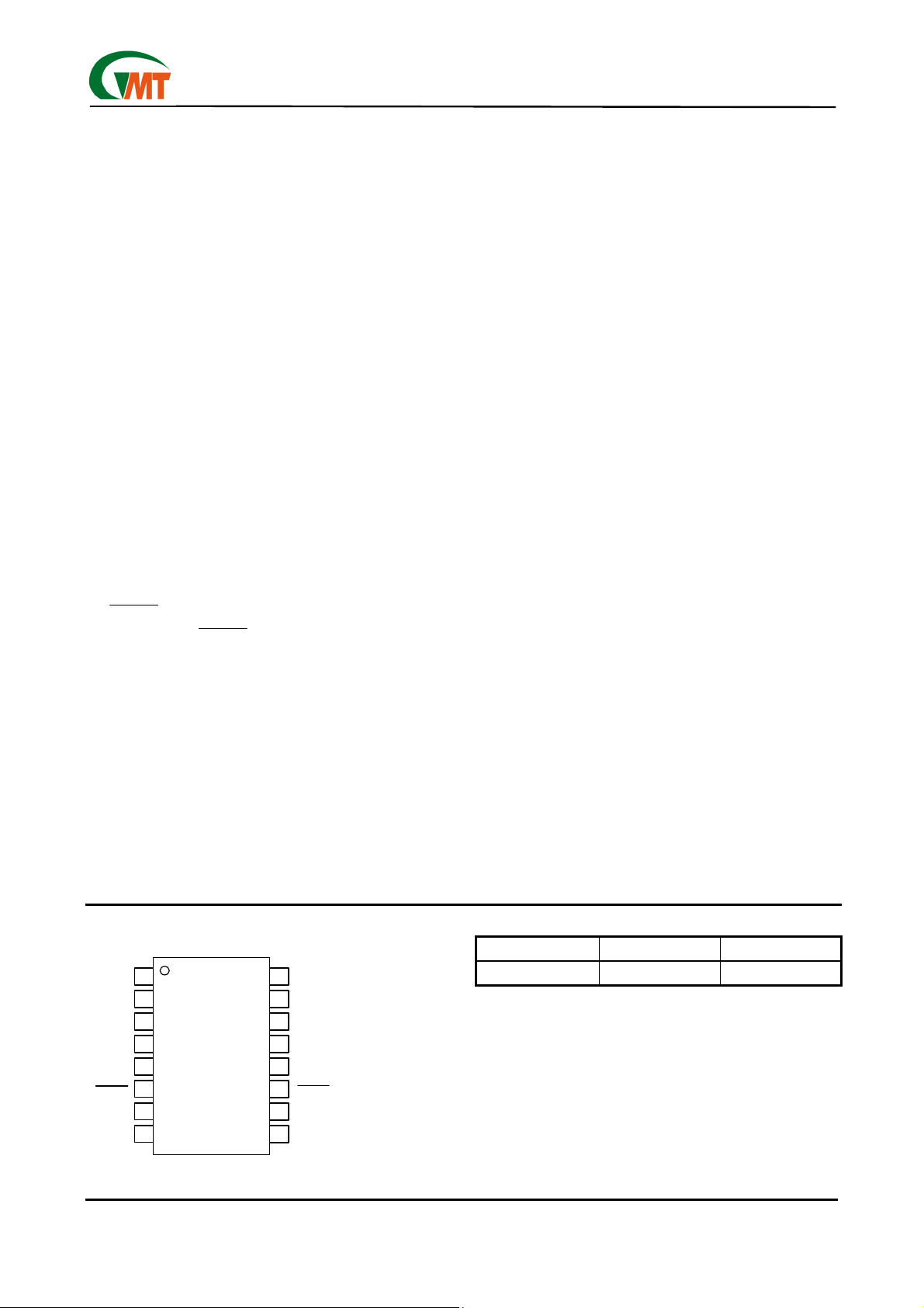
Pin Configuration
General Description
The G768D contains a precise digital thermometer, a
fan controller, and a system-reset circuit.
Except for one less fan controller, G768D is backward
compatible with G768B. G768D has 2 more functions,
fan-failure detection and programmable thermal shutdown signal.
The thermometer reports the temperature of 2 remote
sensors. The remote sensors are diode-connected
transistors typically a low-cost, easily mounted
2N3904 NPN type that replace conventional thermistors or thermocouples. Remote accuracy is ±5°C for
multiple transistor manufacturers, with no calibration
needed. The remote channel can also measure the die
temperature of other ICs, such as microprocessors,
that contain an on-chip, diode-connected transistor.
The 2-wire serial interface accepts standard System
Management Bus (SMBus
TM
) Write Byte, Read Byte,
Send Byte, and Receive Byte commands to program
the alarm thresholds and to read temperature data.
The data format is 7 bits plus sign, with each bit corresponding to 1°C, in two’s-complement format.
Measurements can be done automatically and
autonomously, with the conversion rate programmed
by the user or programmed to operate in a single-shot
mode. The adjustable rate allows the user to control
the supply-current drain.
G768D also contains a fan speed controller. It connects
directly to the fans and performs closed-loop control of
the fan speed independently. The only external component required is a 10µF capacitor per channel. It determines the current fan speed based on the fan rotation
pulses and an externally supplied 32.768KHz clock.
Ordering Information
Vcc
DXP1
DXN
DXP2
RESET
DGND
AGND
1
2
3
4
5
6
7
8
FANVCC
Ver: 1.2
Apr 03, 2002
G768D
16Pin SSOP
16
15
14
13
12
11
10
9
TH_SHUT
Vcc
SMBCLK
NC
SMBDATA
ALERT
FG
CLK
PART NUMBER TEMP. RANGE PIN-PACKAGE
G768D -55°C to +125°C 16SSOP
TEL: 886-3-5788833
http://www.gmt.com.tw
1
Global Mixed-mode Technology Inc.
It uses LDO method and an on-chip MOSFET to control the fan speed to ±2% of the programmed speed.
The desired fan speed is also programmed via
SMBus
read via the SMBus
TM
. The actual fan speed and fan status can be
TM
. Short-circuit protection is implemented to prevent damages to the fan and this IC
itself. The accepted frequency of fan rotation pulses is
100~1000Hz, which corresponds to 3,000 to 30,000
rpm for a typical fan that produces two pulses per
revolution. The G768D also turns on the fans by hardware watchdog system. The fan controller would fully
turn on the fan when any of the following conditions
happens.
1. when either of the remote temperature is higher than
its own T
MAX
.
2.when either of these two remote diodes is open.
3.when both remote diodes are short.
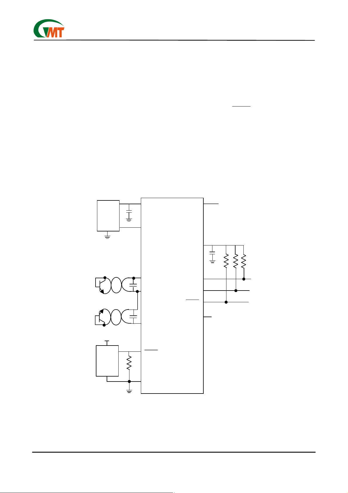
Typical Operating Circuit
IN
FAN1
FAN1
IN
1µF
1µF
FANVCC
FANVCC
G768D
The G768D also contains a microprocessor (µP) supervisory circuit used to monitor the power supplies in
µP and digital systems. They provide excellent circuit
reliability and low cost by eliminating external components and adjustments when used with 5V-powered
circuits. This circuit asserts a reset signal whenever
the V
threshold, keeping it asserted for at least 140ms after
V
has an active-low
parator is designed to ignore fast transients on V
Reset threshold of this circuit is set to 4.4V typical.
The G768D is available in a small, 16-pin SSOP surface-mount package.
TH_SHUT
TH_SHUT
supply voltage declines below a preset
CC
has risen above the reset threshold. The G768D
CC
RESET output. The reset com-
CC
.
2N3904
2N3904
2N3904
2N3904
RESET
RESET
µP
µP
FG
FG
2200pF
2200pF
2200pF
2200pF
FG
FG
DXP1
DXP1
DXN
DXN
DXP2
DXP2
RESET
RESET
GND
GND
G768D
G768D
SMBDATA
SMBDATA
VCC
VCC
SMBCLK
SMBCLK
ALERT
ALERT
CLK
CLK
10µF
10µF
CLOCK 32.768kHz
CLOCK 32.768kHz
10k EACH
10k EACH
SMBCLK
SMBCLK
SMBDATA
SMBDATA
INTERRUPT TO µC
INTERRUPT TO µC
Ver: 1.2
Apr 03, 2002
TEL: 886-3-5788833
http://www.gmt.com.tw
2
Global Mixed-mode Technology Inc.
G768D
Absolute Maximum Ratings
VCC to GND……………….………….…….-0.3V to +6V
DXP1, DXP2 to GND……………0.3V to (V
+ 0.3V)
CC
DXN to GND……………………………...-0.3V to +0.8V
CLK, FG, SMBCLK, SMBDATA,
ALERT
to
GND.……………………….…….………...-0.3V to +6V
SMBDATA,
ALERT
Current…………...-1mA to +50mA
DXN Current………………………………………±1mA
ESD Protection (SMBCLK, SMBDATA,
Stresses beyond those listed under "Absolute Maximum Ratings" may cause permanent damage to the device. These are
stress ratings only, and functional operation of the device at these or any other conditions beyond those indicated in the operational sections of the specifications is not implied. Exposure to absolute maximum rating conditions for extended periods may
affect device reliability.
ALERT
, hu-
man body model)….……….………….……..….….2000V
ESD Protection (other pins, human body model)…2000V
Continuous Power Dissipation (T
= +70°C) SSOP
A
(de-rate 8.30mW/°C above +70°C)…………667mW
Operating Temperature Range…-55°C to +125°C
Junction Temperature………………....+150°C
Storage temperature Range………-65°C to +165°C
Lead Temperature (soldering, 10sec)……….+300°C
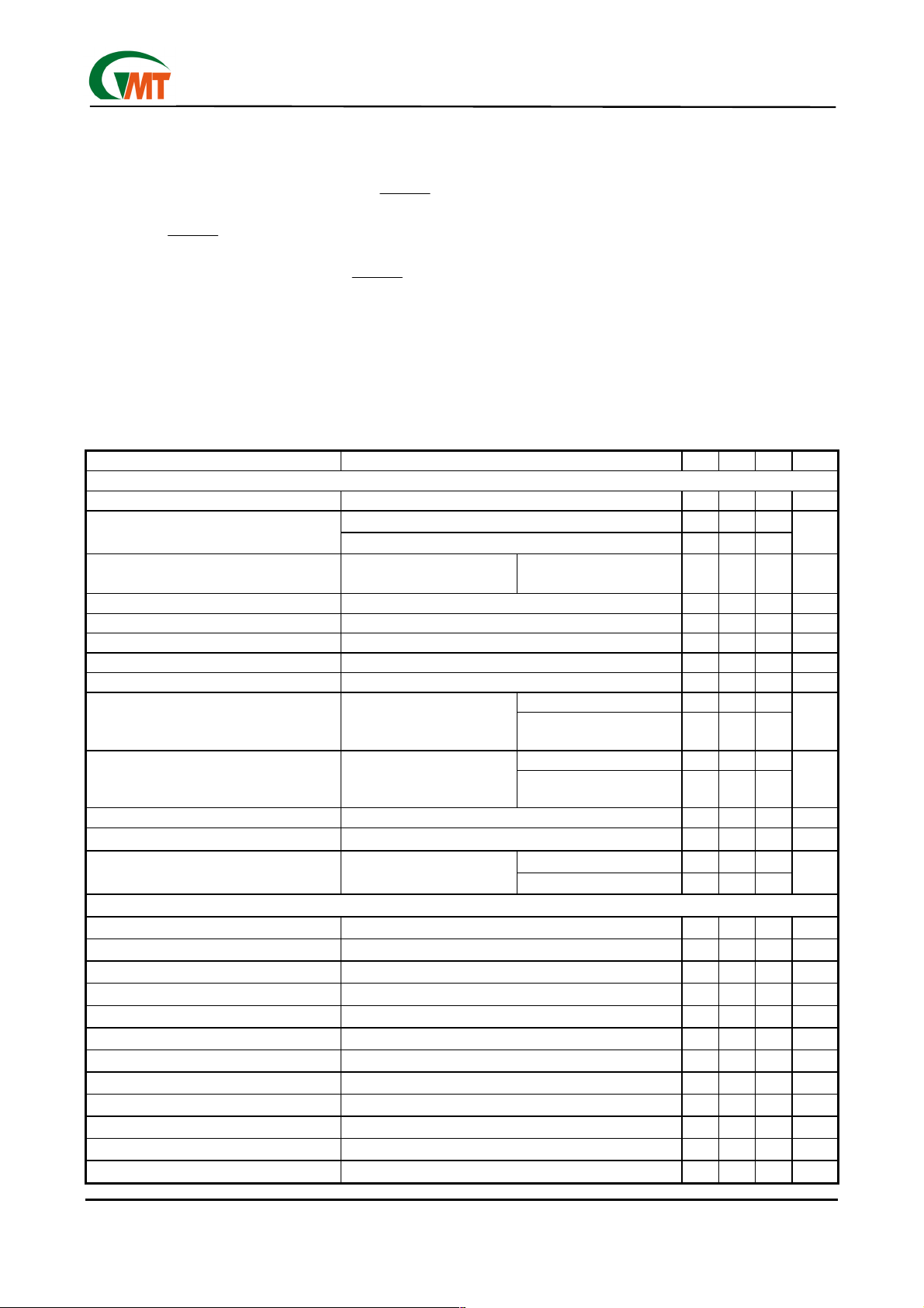
Electrical Characteristics
(VCC = + 5V, TA = 60°C, unless otherwise noted.)
PARAMETER CONDITIONS MIN TYP MAX UNITS
Temperature Sensor
Temperature Resolution (Note 1) Monotonicity guaranteed 8 Bits
Temperature Error, Remote Diode (Notes 2
and 3)
Temperature Error, Local Diode
(Notes 1 and 2)
Supply-Voltage Range 4.5 5 5.5 V
Under-voltage Lockout Threshold VCC input, disables A/D conversion, rising edge 2.6 2.8 2.95 V
Under-voltage Lockout Hysteresis 50 mV
Power-On Reset Threshold VCC, falling edge 1.0 1.7 2.5 V
POR Threshold Hysteresis 50 mV
Standby Supply Current
Average Operating Supply Current
Conversion Time From stop bit to conversion complete (all channels) 94 125 156 ms
Conversion Rate Timing Error Auto-convert mode -25 25 %
Remote-Diode Source Current DXP forced to 1.5V
Fan Controller
Supply voltage VCC 4.5 5 5.5 V
Shutdown current Fan speed = 0rpm 2 5 µA
MOSFET on resistance 0.2 0.25
Short-circuit current limit 0.5 A
Input logic low VIL 0.7. V
Input logic high VIH 1.0 V
Clock frequency CLK 32.768 KHz
FANVCC over-current trig 600 mA
FANVCC current limit 500 mA
FG input Positive-going threshold voltage VCC=5V 1 V
FG input Negative-going threshold voltage VCC=5V 0.7 V
FG input Hysteresis voltage VCC=5V 0.3 V
TR = 0°C to +125°C -5 5
= 60°C to +100°C -3 3
T
R
Including long-term drift T
Logic inputs forced to V
GND
Auto-convert mode, average
measured over 4sec. Logic
inputs forced to V
or GND
CC
CC
= +60°C to +100°C -3 3 °C
A
SMBus static 3 10
or
Hardware or software
standby, SMBCLK at 10kHz
0.25 conv/sec 250 300
2.0 conv/sec 300 350
High level 120 160 200
Low level 15 20 25
200
°C
µA
µA
µA
Ω
Ver: 1.2
Apr 03, 2002
3
TEL: 886-3-5788833
http://www.gmt.com.tw
Electrical Characteristics
Global Mixed-mode Technology Inc.
(continued)
G768D
(VCC = + 5V, TA = 60°C, unless otherwise noted.)
PARAMETER CONDITIONS MIN TYP MAX UNITS
SMBus Interface
Logic Input High Voltage SMBCLK, SMBDATA; VCC = 4.5V to 5.5V 2.4 V
Logic Input Low Voltage SMBCLK, SMBDATA; VCC = 4.5V to 5.5V 0.8 V
Logic Output Low Sink Current
Output High Leakage Current
ALERT
Logic Input Current Logic inputs forced to VCC or GND -2 2 µA
SMBus Input Capacitance SMBCLK, SMBDATA 5 pF
SMBus Clock Frequency (Note 4) DC 100 KHz
SMBCLK Clock Low Time t
SMBCLK Clock High Time t
SMBus Start-Condition Setup Time 4.7 µs
SMBus Repeated Start-Condition
Setup Time
SMBus Start-Condition Hold Time t
SMBus Start-Condition Setup Time t
SMBus Data Valid to SMBCLK RisingEdge Time
SMBus Data-Hold Time t
SMBCLK Falling Edge to SMBus
Data-Valid Time
ALERT , SMBDATA forced to 0.4V
forced to 5.5V
ALERT
, 10% to 10% points 4.7 µs
LOW
, 90% to 90% points 4 µs
HIGH
t
t
SMBCLK
Master clocking in data 1 µs
90% to 90% points 500 ns
SU : STA ,
10% of SMBDATA to 90% of SMBCLK 4 µs
HD: STA ,
90% of SMBDATA to 10% of SMBDATA 4 µs
SD: STO ,
10% or 90% of SMBDATA to 10% of
SU: DAT ,
(Note 5) 0 µs
HD : DAT
6 mA
1 µA
800 ns
(continued)
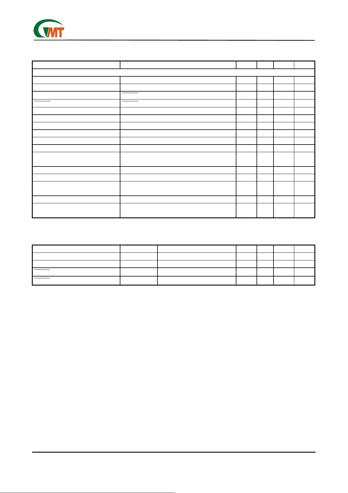
Electrical Characteristics
(VCC =full range, TA= 60°C, unless otherwise noted.)
PARAMETER SYMBOL CONDITIONS MIN TYP MAX UNITS
Reset Threshold VTH 4.2 4.4 4.5 V
Reset Active Timeout Period 340 ms
RESET
Output Voltage Low
RESET
Output Voltage High
Note 1: Guaranteed but not 100% tested.
V
V
OL
V
V
OH
CC=VTH
CC>VTH
min, I
max, I
=3.2mA
SINK
SOURCE
=5.0mA
0.4 V
-1.5 V
V
CC
Note 2: Quantization error is not included in specifications for temperature accuracy. For example, if the G768D
device temperature is exactly +66.7°C, or +68°C (due to the quantization error plus the +1/2°C offset
used for rounding up) and still be within the guaranteed ±3°C error limits for the +60°C to +100°C temperature range. See Table3.
Note 3: A remote diode is any diode-connected transistor from Table1. T
mote diode. See Remote Diode Selection for remote diode forward voltage requirements.
is the junction temperature of the re-
R
Note 4: The SMBus logic block is a static design that works with clock frequencies down to DC. While slow op-
eration is possible, it violates the 10kHz minimum clock frequency and SMBus specifications, and may
monopolize the bus.
Note 5: Note that a transition must internally provide at least a hold time in order to bridge the undefined region
(300ns max) of SMBCLK's falling edge.
Ver: 1.2
Apr 03, 2002
TEL: 886-3-5788833
http://www.gmt.com.tw
4
Global Mixed-mode Technology Inc.
Pin Description
PIN NAME FUNCTION
1 FANVCC Output connected to VCC of fan.
2,15 VCC Supply Voltage Input, 4.5V to 5.5V. Bypass to GND with a 0.1µF capacitor.
Combined Current Source and A/D Positive Input for remote-diode channel 1. Do not leave DXP1 floating;
3 DXP1
4 DXN
5 DXP2
RESET
6
7 DGND Digital Ground.
8 AGND Analog Ground.
9 CLK 32.768KHz clock input for fan controller.
10 FG Fan pulse input.
11
12 SMBDATA SMBus Serial-Data Input / Output, open drain.
13 NC
14 SMBCLK SMBus Serial-Clock Input.
16 TH_SHUT Thermal Shutdown Output, push-pull output.
ALERT
tie DXP1 to DXN if no remote diode on channel 1 is used. Place a 2200pF capacitor between DXP1 and
DXN for noise filtering.
Combined Current Sink and A/D Negative Input. DXN is common negative node of both remote diodes on
channel 1 and 2. The traces of DXP1-DXN and DXP2-DXN pairs should be routed independently. The
common DXN should be connected together as close as possible to the IC. DXN is internally connected to
the GND pin for signal ground use.
Combined Current Source and A/D Positive Input for remote-diode channel 2. Do not leave DXP2 floating;
tie DXP2 to DXN if no remote diode on channel 2 is used. Place a 2200pF capacitor between DXP2 and
DXN for noise filtering.
RESET
the reset threshold.
SMBus Alert (interrupt) Output, open drain.
Output remains low while VCC is below the reset threshold, and for 340ms after VCC rises above
G768D
Detailed Description
The G768D (patents pending) is a 3-in-1 IC. It consists
of one temperature sensor, 1 fan speed controller and
provides system-reset function.
The temperature sensor is designed to work in conjunction with an external micro-controller (µC) or other
intelligence in thermostatic, process-control, or monitoring applications. The µC is typically a powermanagement or keyboard controller, generating SMBus serial commands by "bit-banging" general-purpose input-output (GPIO) pins or via a dedicated SMBus interface block.
Essentially a 12-bit serial analog-to-digital converter
(ADC) with a sophisticated front end, the G768D contains a switched current source, a multiplexer, an ADC,
an SMBus interface, one fan controller, a reset circuit
and associated control logic (Figure 1).
Temperature data from the ADC is loaded into two
data registers, where it is automatically compared with
data previously stored in four over/under-temperature
alarm registers.
ADC and Multiplexer
The ADC is an averaging type that integrates over a
60ms period (each channel, typical).
The multiplexer automatically steers bias currents
through two remote diodes, measures their forward
voltages, and computes their temperatures. All channels are converted automatically once the conversion
process has started, either in free-running or single-shot mode. If one of the two channels is not used,
the device still performs all measurements, and the
user can simply ignore the results of the unused
channel. If the remote diode channel is unused, tie
DXPx to DXN rather than leaving the pins open.
The DXN input is internally connected to the ground
node inside the chip to set up the analog to digital
(A/D) inputs for a differential measurement. The
worst-case DXP-DXN differential input voltage range
is 0.25V to 0.95V.
Excess resistance in series with the remote diode causes
about +1/2°C error per ohm. Likewise, 200µV of offset
voltage forced on DXP-DXN causes about 1°C error.
Ver: 1.2
Apr 03, 2002
5
TEL: 886-3-5788833
http://www.gmt.com.tw
 Loading...