

Page 1
Technical Operations Manual
The most important thing we build is trust.
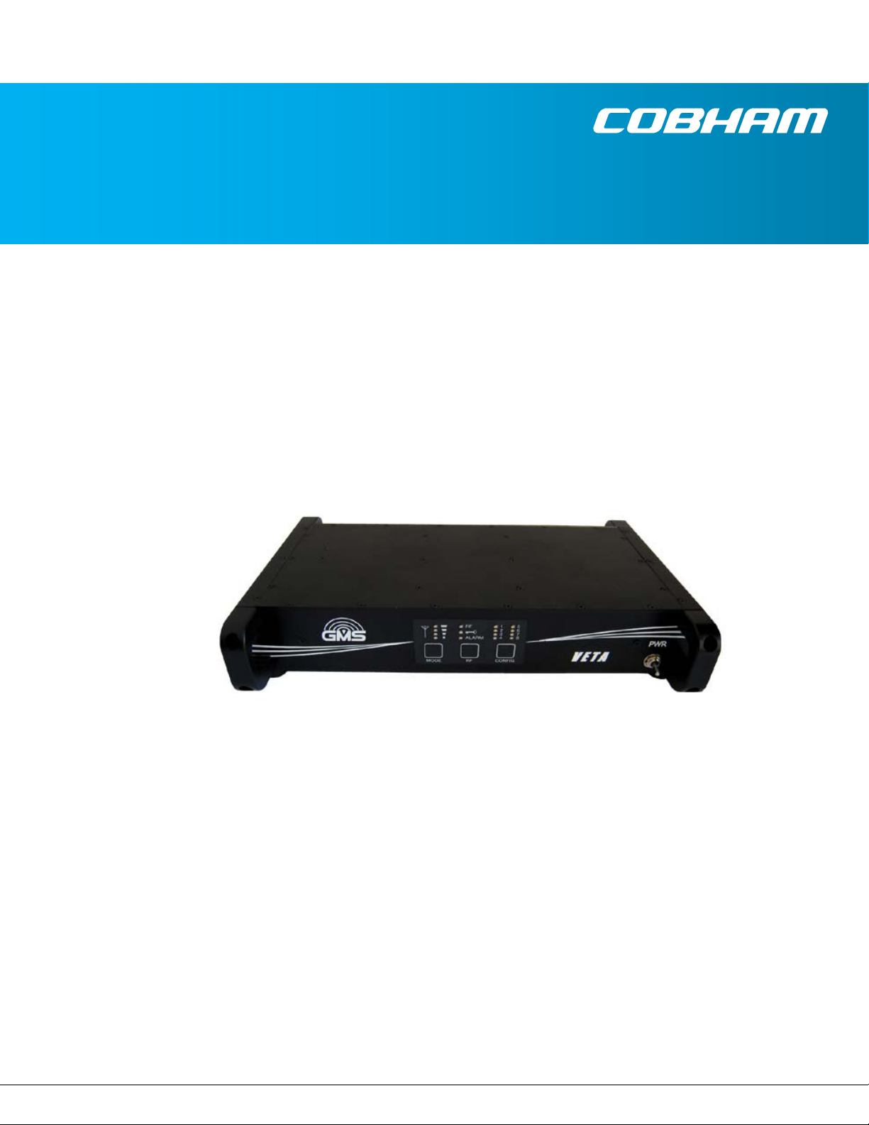
VETA Receiver
Cobham Surveillance
GMS Products
1916 Palomar Oaks Way Ste 100
Carlsbad, CA 92008
100-M0133X1 05/27/09 T: 760-496-0055
F: 760-496-0057
www.cobham.com/gms
Page 2

RevisionHistory
Version Date Main Changes from Previous version Edited by
X1 9‐26‐2009 InitialRelease NM
100-M0133X1 2of33
www.cobham.com/gms
Page 3

Table of Contents
1. ACRONYMS ............................................................................................................................................................................................. 5
2. INTRODUCTION ................................................................................................................................................................................. 6
2.1 Key System Features ....................................................................................................................................................................... 6
3. GENERAL SYSTEM INFORMATION ........................................................................................................................................ 7
3.1 Warranty ............................................................................................................................................................................................... 8
3.2 Safe Operating Procedures .......................................................................................................................................................... 8
4. GETTING STARTED ........................................................................................................................................................................... 9
4.1 Initial Checkout ................................................................................................................................................................................. 9
4.2 Key RF Settings For COFDM Transmission ........................................................................................................................ 10
5. HARDWARE OVERVIEW .............................................................................................................................................................. 12
5.1 VR Front Panel ................................................................................................................................................................................. 12
5.1.1 Power Switch ...............................................................................................................................................................................................12
5.1.2 Received Signal Strength Green LED-s ............................................................................................................................................13
5.1.3 RF Green LED ...............................................................................................................................................................................................13
5.1.4 Lock Yellow LED ..........................................................................................................................................................................................13
5.1.5 Alarm Red LED .............................................................................................................................................................................................13
5.1.6 Green Config LEDS 1 to 8 ......................................................................................................................................................................13
5.1.7 Config Button ..............................................................................................................................................................................................13
5.1.8 RF Button .......................................................................................................................................................................................................14
5.1.9 Mode Button ...............................................................................................................................................................................................14
5.2 VR REAR PANEL .............................................................................................................................................................................. 15
5.2.1 RF AND IF CONNECTIONS ....................................................................................................................................................................15
5.2.2 ASI OUT ......................................................................................................................................................................................................... 16
5.2.3 Video ............................................................................................................................................................................................................... 16
5.2.4 Audio ............................................................................................................................................................................................................... 16
5.2.5 J1 Multifunction DB-15 (F) Connector ............................................................................................................................................17
5.2.6 J2 Multifunction DB-9 (M) Connector .............................................................................................................................................17
5.2.7 RJ-45, VIDEO SERVER (Optional Video Server) ...........................................................................................................................18
5.3 Using External Down-Converters ........................................................................................................................................... 18
6. SOFTWARE CONTROL OVERVIEW ....................................................................................................................................... 22
6.1 System Requirements .................................................................................................................................................................. 22
6.2 Software Installation ................................................................................................................................................................... 22
6.3 VR Configurator Functions ....................................................................................................................................................... 22
7. VETA CHAINING FEATURE ...................................................................................................................................................... 24
7.1 VETA Digital Repeater (VDR) .................................................................................................................................................... 24
7.2 Compact Surveillance Modem (CSM) ................................................................................................................................. 24
7.3 UDP Transmitter ............................................................................................................................................................................ 24
8. SPECIFICATIONS ............................................................................................................................................................................ 25
8.1 C-OFDM RF INPUT........................................................................................................................................................................ 25
8.2 C-OFDM IF INPUT ........................................................................................................................................................................ 25
8.3 DEMODULATION .......................................................................................................................................................................... 25
8.4 VIDEO DECODING ........................................................................................................................................................................ 25
8.5 AUDIO DECODING ....................................................................................................................................................................... 26
100-M0133X1 3of33
www.cobham.com/gms
Page 4

8.6 POWER ................................................................................................................................................................................................ 26
8.7 Physical ............................................................................................................................................................................................... 26
8.8 Environmental ................................................................................................................................................................................. 27
8.9 Optional LAN/USB Interface .................................................................................................................................................... 27
8.10 RS232 DATA OUTPUT ................................................................................................................................................................ 27
8.11 CONTROL ........................................................................................................................................................................................... 27
8.12 REMOTE CONTROL ....................................................................................................................................................................... 27
8.13 LOCAL MONITORING .................................................................................................................................................................. 27
8.14 REMOTE MONITORING .............................................................................................................................................................. 27
8.15 SECURITY OPTION ....................................................................................................................................................................... 27
List of Tables
TABLE 1 – RF CONNECTIONS ......................................................................................................................................................................... 16
TABLE 2 – ASI CONNECTOR ............................................................................................................................................................................ 16
TABLE 3 – VIDEO CONNECTOR ..................................................................................................................................................................... 16
TABLE 4 – AUDIO CONNECTIONS ............................................................................................................................................................... 16
TABLE 5 – J1 MULTIFUNCTION CONNECTOR ....................................................................................................................................... 17
TABLE 6 – J2 MULTIFUNCTION CONNECTOR ....................................................................................................................................... 18
List of Figures
FIGURE 1 – BASIC VDL SETUP .......................................................................................................................................................................... 9
FIGURE 2 – VR RF ESSENTIALS ...................................................................................................................................................................... 11
FIGURE 3 – VR FRONT VIEW .......................................................................................................................................................................... 12
FIGURE 4 – VR FRONT PANEL ......................................................................................................................................................................... 12
FIGURE 5 – VR OSD ............................................................................................................................................................................................. 14
FIGURE 6 – VR REAR VIEW .............................................................................................................................................................................. 15
FIGURE 7 – BDC SETTINGS WINDOW ....................................................................................................................................................... 20
FIGURE 8 – EXTERNAL BDC SETUP .............................................................................................................................................................. 21
FIGURE 9 – VR CONFIGURATOR COM PORT SELECTOR ................................................................................................................... 23
FIGURE 10 – VR CONFIGURATOR MAIN SCREEN ................................................................................................................................ 23
List of Appendixes
APPENDIX A – LED INDICTORS ..................................................................................................................................................................... 28
APPENDIX B – TROUBLESHOOTING SECTION ....................................................................................................................................... 29
APPENDIX C – CONTROL CABLE ................................................................................................................................................................... 30
APPENDIX D – VR DEFAULTS, LS BAND .................................................................................................................................................... 31
APPENDIX E – VR DEFAULTS, S1 BAND..................................................................................................................................................... 32
APPENDIX F – VR DEFAULTS, C2 BAND .................................................................................................................................................... 33
100-M0133X1 4of33
www.cobham.com/gms
Page 5

1. Acronyms
Thissectionlistsanddescribesthevariousacronymsusedinthisdocument.
Name Meaning
16QAM 16‐stateQuadratureAmplitudeModulation
A/V Audio/Video
AES AdvancedEncryptionSystem
ABS BasicEncryptionSystem(8bit)
CSM CompactSurveillanceModem
COFDM CodedOrthogonalFrequencyDivisionMultiplexing
CVBS CompositeVideo
BDC Block‐DownConverter
FEC ForwardErrorCorrection
GUI
I/O
KBaud Kilobaudpersecond
Kbps Kilobitspersecond
Mbps Megabitspersecond
MER ModulationErrorRate
MPEG MovingPictureExpertsGroup
NTSC NationalTelevisionSystemCommittee
PAL PhaseAlternationLine
QAM QuadratureAmplitudeModulation
QPSK QuadraturePhaseShiftKeying
RF RadioFrequency
RX Receiver
S/N Signal‐to‐NoiseRatio
THD TotalHarmonicDistortion
TX Transmitter
UDP UserDatagramProtocol
VDC Volts(DirectCurrent)
VDL VETADigitalLink
VDR VETADigitalRepeater
VMT VETAMiniatureTransmitter
VNA VETANetworkAdapter
VR VETAReceiver
VT VETATransmitter
Graphical User Interface
Input/ Output
100-M0133X1 5of33
www.cobham.com/gms
Page 6

2. Introduction
GMS’ Very Efficient Transmission Apparatus (VETA) product line provides several key features that
enable high-quality and low-latency wireless Audio/Video (A/V) transmission for the most demanding
short or long distance point to point or to multipoint transmission applications. VETA uses a robust
digital modulation system known as Coded Orthogonal Frequency Division (COFDM) that provides a
robust link that is immune to multipath interference and provides crisp, clear pictures in the most
difficult of terrains.
This manual provides information on how to operate the VR (VETA Receiver) as well as pertinent
technical information related to the overall system.
2.1 Key System Features
(1)
COFDM Demodulation 2K Carriers or 400
Bandwidths from 1.25
(2)
MHz to 8 MHz
Input Frequency: 0.174 to 8.5 GHz (In-Bands)
Internal or External Down-Converters
Low End to End System Latency (down to ~44mS)
Secure – ABS / BCRYPT 128 or 256 Encryption
(3)
Optional LAN IP Streaming Interface
Optional Video Server
(1), (2)
400 carriers is optional with the 1.25 or 2.5MHz RF bandwidths
(3)
BCRYPT 128 or 256 bit optional
100-M0133X1 6of33
www.cobham.com/gms
Page 7

3. General System Information
The VR (VETA Receiver) receives and demodulates DVB-T 2k carriers’ signals with bandwidths of 6, 7
or 8 MHz. Additionally, optional 1.25 or 2.5 MHz RF bandwidths with 400 carriers allow both
increased reception range and larger quantity of simultaneous A/V links to operate in the same
frequency band. The wider bandwidths provide greater throughput that allow the system to transfer
the highest quality video.
The standard VR is supplied with dual Diversity inputs and internal RF Block-Down Converters (BDCs)
with a user selected (at time of purchase) frequency band. The VR’s Maximal Ratio Diversity Combiner
provides optimum reception in difficult fading and multipath environments. Additionally, the Diversity
combining can provide up to 2.5 dB in link performance, increasing the receiver’s sensitivity to -97.5
dBm at 8 MHz bandwidth! Optional external GMS BDCs are available that can support other frequency
bands and optimize reception when mounted directly to remote Antennas. These remote BDC can be
powered from the IF line of the VR or, their own power supply. The VR can also be optional supplied
with internal LNAs for operation below 860 MHz or no internal Down-Converter or LNA. The latter
option is used when the BDC is remotely mounted, usually with an Antenna.
One of the biggest problems encountered in the transition from analog to digital A/V systems has been
the inherent digital coding/decoding delays that in some digital systems are 400ms or more. The
VETA Transmitters & Receivers employ internal MPEG-2 or MPEG-4
(4)
(User Selectable) Encoders and
Decoders with specially designed ‘low-delay’ coding technology, which provides an end to end latency
down to 44ms without the introduction of any further MPEG encoding artifacts. This ensures that
the picture you see is what is happening now - crucial for applications such as surveillance, and law
enforcement, where personnel are reacting to real-time events.
Control and status monitoring can be accomplished via the VR Front Panel or via an external IBM PC
and GMS’ M.S. Windows application control software. Critical performance parameters like Signal To
Noise Ratio (SNR), Pre and Post FEC Bit Error Rate (BER) and Packet Errors are provided
both on the On-Screen Display and M.S. Windows control program.
The VR also includes internal low-latency Audio/Video Decoder (MPEG-2 or MPEG-4
(4)
) and output
circuits that provide video, L/R audio and data channels. Security of transmission is ensured by the use
of Standard ABS encryption or, for greater security, the optional BCRYPT 128 or 256 bit scrambling
algorithms.
The optional VETA IP Network Adapter (VNA) provides the VR with a video streaming capability for
network interfacing. An optional M.S. Windows software Decoder and Recording application is also
available. See Section 7 on VETA ‘Chaining’ feature. Alternatively the VR can have an integrated video
server installed for web streaming applications.
The VR’s versatile housing can be optionally mounted in a suitcase, can sit on a desktop, or be
configured to mount in a 19-inch instrumentation rack.
(4)
Option Dependant
100-M0133X1 7of33
www.cobham.com/gms
Page 8

3.1 Warranty
GMS offers a 12 month standard product warranty. During this period, should the customer encounter
a fault with the equipment we recommend the following course of action:
Check the support section of the website for information on that product and any
software/firmware upgrades.
If fault persists call our support line and report the fault. If fault persists and you are
informed to return the product, please obtain an RMA number from the GMS support
department or website and ship the equipment with the RMA number displayed and a
description of the fault. Please email the support section the airway bill/consignment
number for tracking purposes.
Depending on the nature of the fault GMS endeavor to repair the equipment and return it to the
customer within 14 days of the item arriving at our workshops. Obviously it is impossible to cater for
all types of faults and to manage 100% replacement part availability, and delays are sometimes
inevitable.
Please contact GMS for details of packages that can be tailored to meet your individual needs,
whether they are service availability, technical training, local geographic support or dedicated spares
holdings.
3.2 Safe Operating Procedures
• Ensure that the power supply arrangements are adequate to meet the requirements of VETA
product.
• Operate within the environmental limits specified for the product.
• Only authorized, trained personnel should open the product. There are no functions that
required the User to gain access to the interior of the product.
100-M0133X1 8of33
www.cobham.com/gms
Page 9
4. Getting Started
(VT)
The VR is pre-configured by GMS prior to shipment (based on customer requirements), thus is ready to
work “right out of the box”.
NOTE: Additional cables and antennas may be delivered by GMS based on customer application.
Contact GMS for further information.
4.1 Initial Checkout
Prior to installing a VR unit into the desired target environment, an initial checkout should be
performed to ensure proper operation of the unit. The initial checkout consists of configuring a
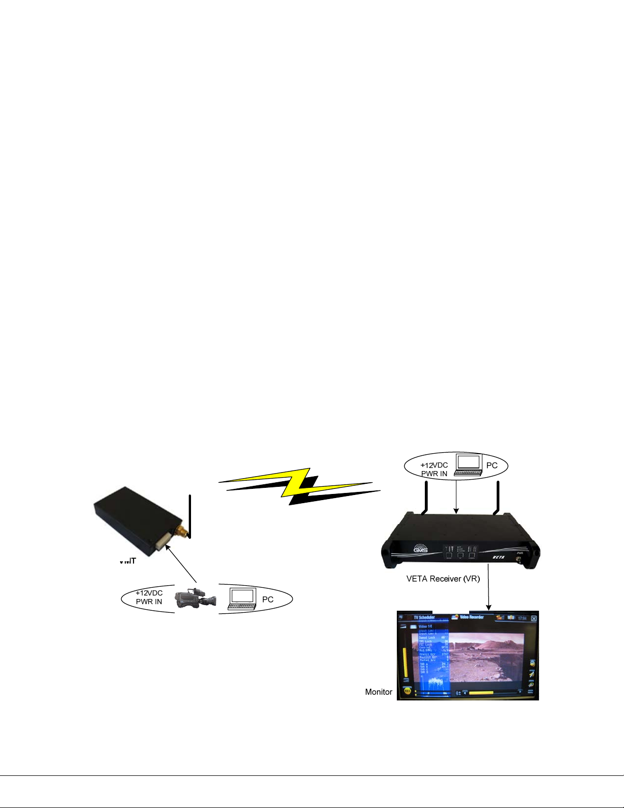
basic VDL (Veta Digital LINK) wireless link. In the case outlined, we will assume a VETA
Miniature Transmitter (VMT) is used to transmit to the VR. Note, that any MPEG-2, DVB-T
compliant transmitter can be employed instead if the VR is set-up in standard DVB-T Mode (RF
BW 6, 7, or 8 MHz) and not in ultra-low delay mode.
Figure 1 shows a basic VDL configuration wireless link. The following setup can be done, either
wirelessly with antennas, or through hard line connection with 50Ω cable. In either case, make
sure there is enough attenuation from the Tx to the Rx to avoid overdriving the receiver. In
most DVB-T receivers, their optimal input power ranges from -30 to -70 dBm. The VR shown
has internal BDCC installed locally within unit, which is our standard VR configuration. The steps
necessary to setup the configuration shown are stated below:
(VR)
Figure 1 – Basic VDL Setup
100-M0133X1 9of33
www.cobham.com/gms
Page 10

Install omni-directional antennas (or ones best suited for the application) onto the RF IN A
and RF IN B ports on the Veta Receiver and one on the SMA RF connector on the VMT.
(Hard lined connection can be made instead, make sure enough attenuation is present
when performing a hard line checkout)
Attach the VMT breakout cable (780-C0449 or equivalent) and apply +12VDC to the red
pigtail and GND to the black pigtail. Ensure power supply can supply at least 0.5A at
+12VDC.
Attach a composite video source to the BNC video input cable that is located on the VMT
breakout cable.
Note which VMT Configuration 1 through 16 is shown (rotary switch or through control
software); this number must match the receiver.
Attach a video cable from BNC VID output port on the VR (VETA Receiver) to the
composite Video input port of a video monitor.
Apply +12Vdc to the VR, pins 1, 2, +12V and 3, 4 ground to the J2 dB connector (if using
provided cable use the red (+12V) and black (GND) pigtails. Power supply must be able to
source 2 AMP at 12VDC.
Turn on the video source and video monitor equipment.
Turn on the VR with the PWR switch on the front panel (up is ON). The VR will output a
‘blue’ screen to your video monitor when no video is present to the VR.
Once the VR has powered-up, ensure the selected green LED1 through 16 (above the
CONF button) matches the same configuration LED as the transmitter. If not use the
CONF button to select the correct configuration, select the same number as the
transmitter. (See section 5.1.6 for explanation of binary representation of configs).
If the configuration LED is flashing green press the RF button on the front keypad (this
action provides power to the internal down converters) and the LED will stay solid green.
After approximately 5 seconds, the link should be established and video provided by the
source should be displayed on the monitor. The RF green LED should light as well as the
signal strength green LED indicators.
Press the MODE button to turn on the diagnostic OSD (on screen display).
If the red Alarm LED lights it may be an indication that the receiver is unable to lock to a
signal. Check the following:
Ensure the receiver and transmitter lit configuration green LED (1 through 16)
located above the CONFIG button is the same. If not press the CONFIG button
on either the transmitter or receiver so they match.
Ensure the PWR switch for the VR is ON and that the RF button has been pressed
after apply +12VDC.
If the TX and RX are physically too close to each other, the RX may overload
causing distorted Video. You may reduce the power of the TX (low power mode
through VMT GUI) or move the TX & RX further apart. 50 Ohm RF attenuators can
also be used to attenuate power from the Tx.
4.2 Key RF Settings For COFDM Transmission
The RF settings shown in Figure 2 show the key COFDM configurations for setting up any
COFDM link. The settings underlined in RED must be matched specifically to the VETA
Transmitter for proper RF lock and demodulation (the other COFDM parameters are auto-
100-M0133X1 10of33
www.cobham.com/gms
Page 11
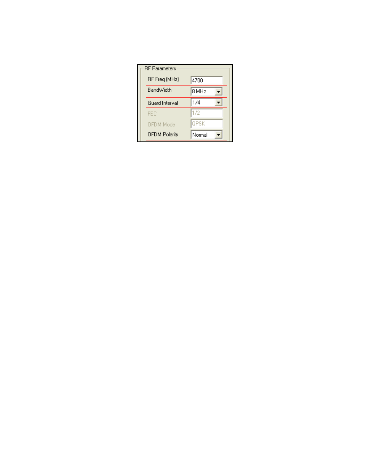
detected). In general, when troubleshooting a RF link, the operator should make sure that the
following RF parameters are matched at both the Transmitter and Receiver.
Figure 2 – VR RF Essentials
The initial checkout described above is simply to check the basic video operation of the VR unit.
For further details on the connectors, monitoring and controlling the VR read thoroughly
through this manual starting with section 5, hardware overview, and section 6. For a full
explanation of the control software see Manual: 100-M0131.
100-M0133X1 11of33
www.cobham.com/gms
Page 12
5. Hardware Overview
The VR versatile housing can be optionally mounted in a suitcase, sit on a desktop or be configured to
mount in a 19 inch instrumentation rack.
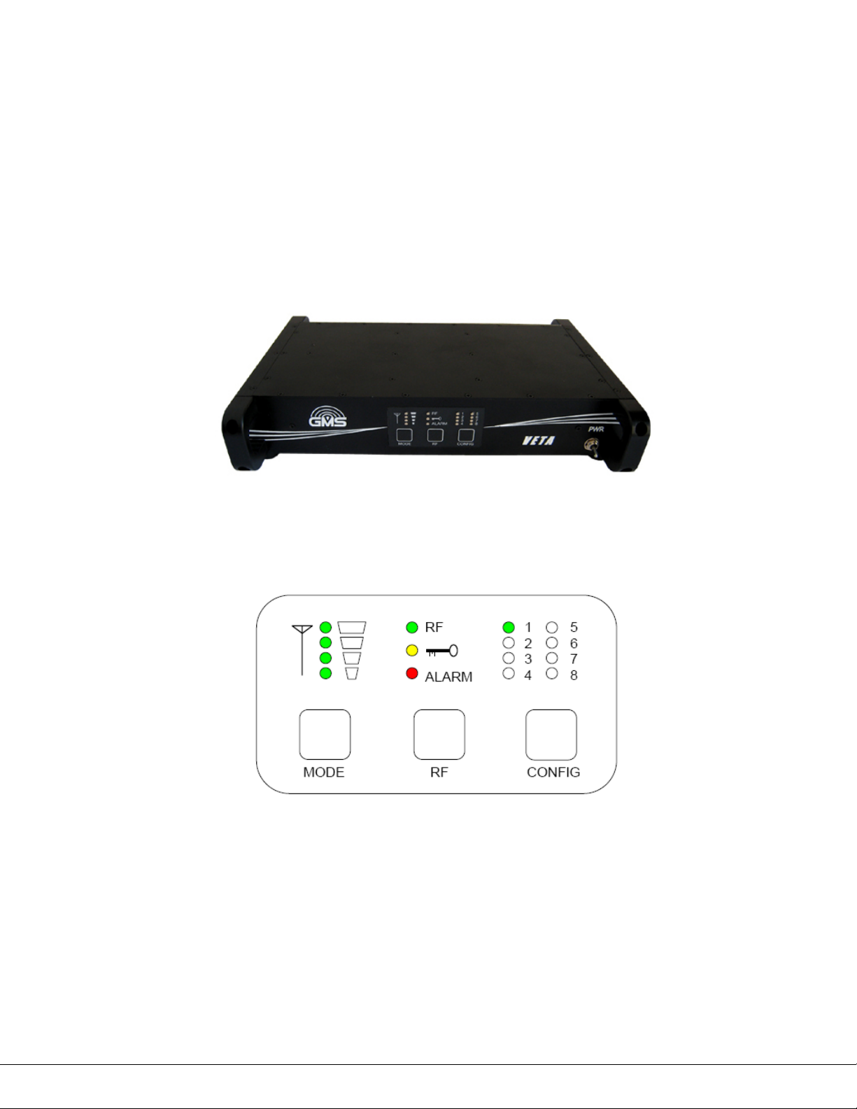
All interface connectors are located in the back of the unit. The front consists of a standard push
button panel, LED indicators and a toggle power switch. The front and back panels of the VR unit are
illustrated in Figure 3, 4 and 6 and discussed in detailed in this section.
5.1 VR Front Panel
The front button panel, LED indicators and power switch are explained in this section.
Figure 3 – VR Front View
Figure 4 – VR front panel
5.1.1 Power Switch
The Power Switch located on the far right side of the panel enables +VDC to the system; up
position is ON, down position is OFF. On powering the VR, the eight green configuration LED-s
(see section 5.1.6) will light up indicating the current configuration (the one that was active
100-M0133X1 12of33
www.cobham.com/gms
Page 13

when the VR power was turned off). In addition the red Alarm LED (see section 5.15) may light
if the VR is unable to lock or decode the incoming signal.
5.1.2 Received Signal Strength Green LED-s
The green LED-s (located above the MODE button) when ON indicate the signal strength (the RF
input power level) from the minimum (no LEDs light) to the maximum strength (all four LEDs
light).
5.1.3 RF Green LED
The RF green LED indicator (located above RF button) when ON indicates that the VR is locked
to the incoming signal; system is operating normally.
5.1.4 Lock Yellow LED
The LOCK (key icon) yellow LED indicator (located above the RF button) when is ON indicates
that incoming signal is encrypted.
5.1.5 Alarm Red LED
The Alarm red LED indicator (located above the RF button) indicates a fault condition or an
alarm when ON. This can be an indication that there is no RF lock; no video in the Transport
Stream or non matching Encryption Key.
5.1.6 Green Config LEDS 1 to 8
The 8 green LEDs (located above the CONFIG button) indicate which one of the sixteen stored
configurations is currently selected. Stored configurations are discussed in Section 6 of this
manual and in section 5.1.8 below. If Config LED is flashing, the BDC power is OFF, and the RX
will not be able to receive a signal through the BDC.
The sixteen configurations are represented in binary format with LED-4 being the most
significant bit, and LED-1 being the least significant. (Note: LED-5 will always be light, which
indicates receiver is in 16-configuration mode). When LEDs 1-4 are all light, this represents
config group 16, while when LEDs 1-4 are off, this represent config group 1.
5.1.7 Config Button
The Config button, when pressed, selects the next configuration from memory. The user will
see the LEDs on the front panel increment in a binary fashion. The 16 configurations in memory
define all potential variables including center frequency, modulation bandwidth, Guard Interval
and OFDM polarity. See section 6 and software manual 100-M0131 for a full discussion on
setting the parameters for each configuration.
100-M0133X1 13of33
www.cobham.com/gms
Page 14
Note that this configuration selection (1 through 16) must match the transmitter’s OFDM
modulation parameters selection for the link to work.
5.1.8 RF Button
Pressing the RF button toggles (ON/OFF) DC power to the Block-Down Converters.
Flashing Config LED indicates OFF state, and solid green – ON state. When using the internal
BDCC, the DC power must be on.
5.1.9 Mode Button
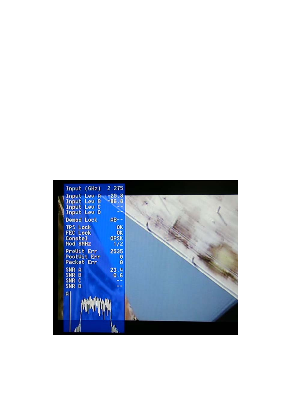
Pressing the Mode button toggles the diagnostic On Screen Display (OSD). Pressing the mode
button will toggle the OSD on with the spectrum display showing input A from the Composite
Video output port. Pressing the mode button a second time will change the spectrum display to
input B. Pressing a third time will turn the OSD off. The diagnostic data (displayed on top of the
current video) includes, signal to noise data, input power level, frequency as well as some
captured parameters from the incoming RF signal, as shown in Figure 5. The OSD is explained in
detail in Manual 100-M0131.
Figure 5 – VR OSD
100-M0133X1 14of33
www.cobham.com/gms
Page 15
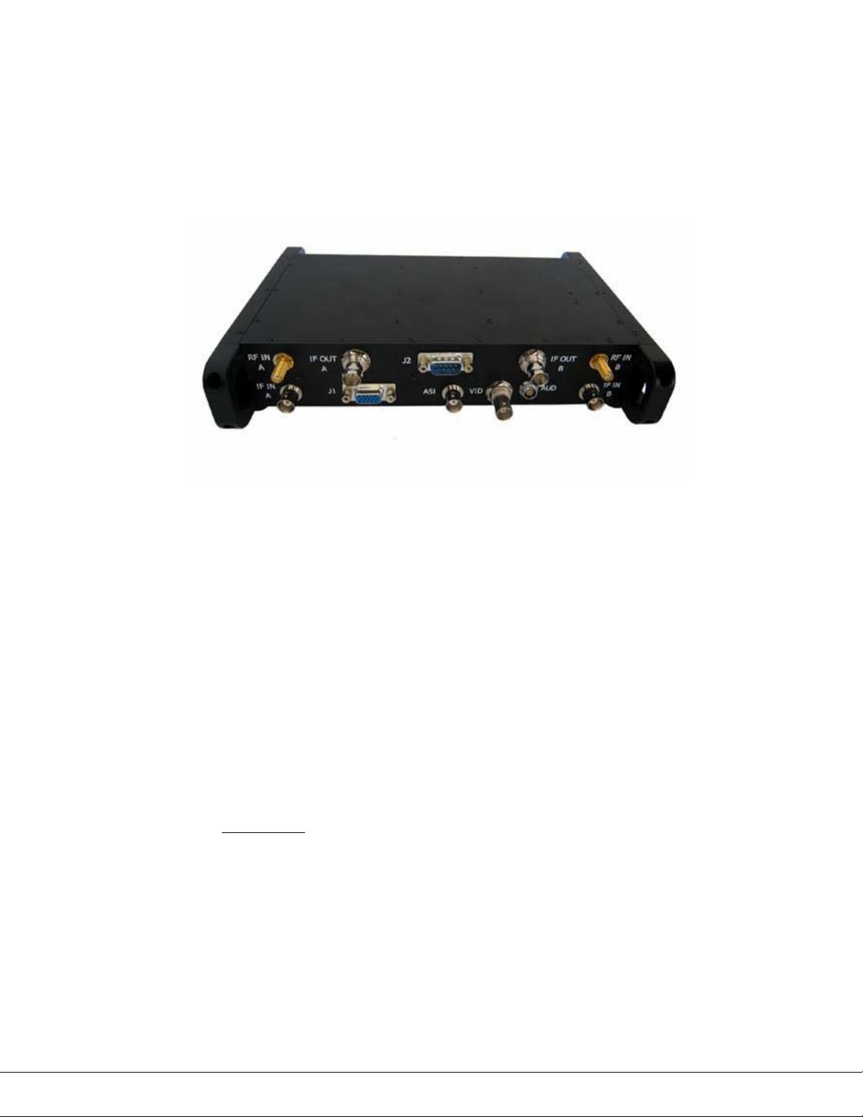
5.2 VR REAR PANEL
The rear panel contains the connectors necessary for interfacing to the VR. Detailed
descriptions of all the VR connectors and components (see Figure 6) are included in the
following sections.
Figure 6 – VR Rear View
5.2.1 RF AND IF CONNECTIONS
The VR can be configured with internal down converters, which is the normal default hardware
setup, or with external down converters.
When using internal down converters the antennas are connected to the diversity RF input, RF
IN A and RF IN B. Internal down converters take the microwave RF signal and down convert it
to the UHF intermediate frequency (IF) which comes out on IF OUT A and IF OUT B BNC
connectors. The IF OUT A and IF OUT B are then connected with external cables to the IF IN A
and IF IN B BNC connectors respectively.
If using external down converters the IF outputs from the external down converters are
connected to the IF IN A and IF IN B (in this scenario the RF IN A / B and IF OUT A /B are not
used). See section 5.3 below on using external down converters.
WARNING: external down converters can be supplied with +12VDC
through the IF IN A or IF IN B ports (from the VR). Ensure the external DC
can handle the +12VDC through the IF port before activating power (or for
that matter ensure the power is off before connecting) otherwise damage
could occur to the down converters. The +12V power can be activated using
GMS control software or the RF button on the front panel.
100-M0133X1 15of33
www.cobham.com/gms
Page 16
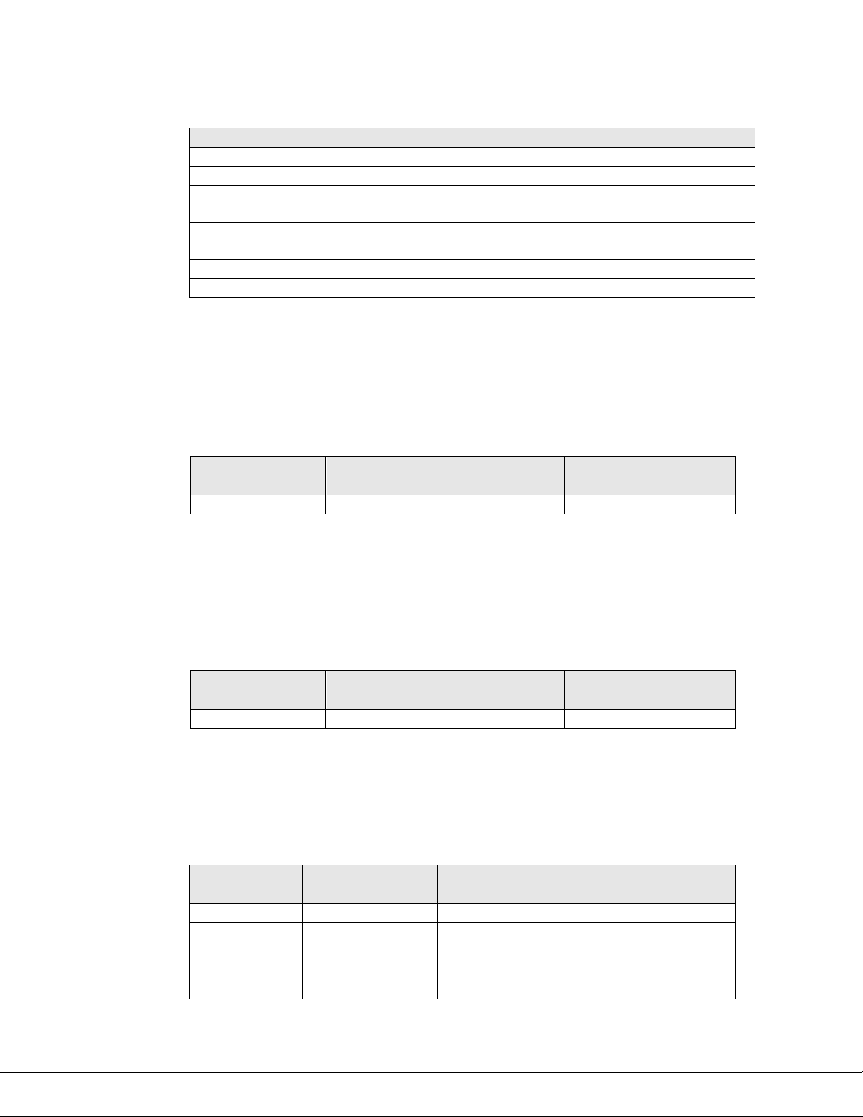
Table 1 – RF Connections
Connector Name Connector Type Comments
RF IN A SMA (F) To internal down converter
RF IN B SMA (F) To internal down converter
IF OUT A BNC(F) From internal down
IF OUT B BNC(F) From internal down
IF IN A BNC(F) To demodulator/decoder
IF IN B BNC(F) To demodulator/decoder
5.2.2 ASI OUT
One ASI (asynchronous serial interface) connector is provided. This is a 75 ohm AC coupled
output. The ASI can be used if external decoders are preferred, or to a ASI recorder or
Multiplexer.
Table 2 – ASI Connector
converter
converter
Connector
Name
ASI BNC (F) ASI out stream
5.2.3 Video
One composite video out 75 ohm impedance, PAL/NTSC standard is provided. S-Video output is
also provided but is located on the multifunction J1 dB-15 (F) connector which is described
under section 5.2.5.
Table 3 – Video Connector
Connector
Name
VID BNC (F) Composite video out
5.2.4 Audio
A Lemo 5 pin connector is provided for audio output. The output level is nominal line level with
output impedance of 50 ohm. Audio is single ended. There are no audio gain adjustments.
Table 4 – Audio Connections
Connector Type Comments
Connector Type Comments
Connector
Name
Connector
Type
PIN Function
AUD Lemo 5-PIN (F) 1 NC
AUD Lemo 5-PIN (F) 2 NC
AUD Lemo 5-PIN (F) 3 GND
AUD Lemo 5-PIN (F) 4 LEFT AUDIO
AUD Lemo 5-PIN (F) 5 RIGHT AUDIO
100-M0133X1 16of33
www.cobham.com/gms
Page 17

5.2.5 J1 Multifunction DB-15 (F) Connector
The multifunction DB-15 connector provides for DC power out, received signal strength
indicator, A & B, S-Video output and the necessary clocks, data and grounds for the optional
chaining interface (an interface which allows multiple services to be sent via one RF link).
The DC power out is basically a loop through from the DC power in and should reflect the input
DC level (see section 5.2.6). It is used to provide power for optional equipment and setups.
S-Video provides a step up in terms of video quality from composite video out (as described in
section 5.2.3) and be taken from pins 14 and 15.
The remaining pins and their functions are described in the table below.
Table 5 – J1 Multifunction Connector
Connector
Name
Connector
Type
Pin Function Comments
J1 DB - 15 (F) 1 PWR OUT 9VDC-18VDC
J1 DB - 15 (F) 2 PWR OUT
J1 DB - 15 (F) 3 GND
J1 DB - 15 (F) 4 GND
J1 DB - 15 (F) 5 RSSI A 0 - 4.5V
J1 DB - 15 (F) 6 RSSI B 0 - 4.5V
J1 DB - 15 (F) 7 Chain CLK OUT
J1 DB - 15 (F) 8 GND
J1 DB - 15 (F) 9 Chain DATA OUT
J1 DB - 15 (F) 10 Chain CLK IN
J1 DB - 15 (F) 11 GND
J1 DB - 15 (F) 12 Chain DATA IN
J1 DB - 15 (F) 13 GND
J1 DB - 15 (F) 14 S-LUMA OUT
J1 DB - 15 (F) 15 S-CHROMA OUT
5.2.6 J2 Multifunction DB-9 (M) Connector
The multifunction DB-9 connector provides for DC power in, RS232 TX & RX control and RS232
TX & RX data.
The DC nominal voltage is 12VDC, minimum is 9VDC and maximum should not exceed 18VDC.
Reverse polarity protection is provided but no protection for over voltage. Power pins 1 & 2
are internally connected as well as ground pins 3 &4.
The receiver can be controlled remotely with GMS PC control software (which is explained in
more detail in Manual 100-M0131). This is done by connecting the PC RS232 transmit and
receive lines to the RS232 TX CTRL and RS232 RX CTRL, pins 5 and 6.
In addition serial RS232 data, sent from the transmitter, can be received on pins 8 & 9, RS232
TX DATA and RS232 RX DATA using a PC RS232 port or another appropriate device.
100-M0133X1 17of33
www.cobham.com/gms
Page 18

The remaining pins and their functions are described in the table below.
Table 6 – J2 Multifunction Connector
Connector
Name
Connector
Type
Pin Function Comments
J2 DB - 9(M) 1 PWR IN 9VDC -18VDC
J2 DB - 9(M) 2 PWR IN
J2 DB - 9(M) 3 GND
J2 DB - 9(M) 4 GND
J2 DB - 9(M) 5 RS232 TX CTRL
J2 DB - 9(M) 6 RS232 RX CTRL
J2 DB - 9(M) 7 GND
J2 DB - 9(M) 8 RS232 TX DATA
J2 DB - 9(M) 9 RS232 RX DATA
5.2.7 RJ-45, VIDEO SERVER (Optional Video Server)
A VETA Receiver can optionally be configured to have an integrated video server installed. The
video output from the VR will now show an overlay generated via the video server. When
connected to a valid network the Video server will show its’ IP address on the video output as an
overlay. If no Ethernet is connected, an icon of a RJ-45 with an ‘X’ through it will show in the
upper right corner of the video output to indicate no network connection was made.
When a valid network has been attached, the user can open their internet browser and enter the
IP address shown on the video overlay. The video shown at the video output of the VR should
now be simultaneously streaming to the web browser. In order to make changes to the video
server, the user will need the username and password:
The default user name is: admin
The default password is: 9999
To turn off the video overlay:
Suppose, for example that the IP address of the device is 192.168.1.168. The user would type
in: http://192.168.1.168/tailpage.htm. (After login) The user would select “ON” or “OFF” in the
OSD column.
Warning: Please write down the IP address of the device before turning off the
OSD.
For more details on the video server, see the Video Server Manual.
5.3 Using External Down-Converters
Down converters have an LO (local oscillator) which is mixed with the DVB-T transmitter
frequency and it then converts it to the IF - intermediate frequency. The VR (VETA receiver)
locks on to the IF frequency in order to be able to receive the C-OFDM signal. The VR calculates
100-M0133X1 18of33
www.cobham.com/gms
Page 19

the IF frequency based on the LO (in MHz) of the down converter as well as the DVB-T
transmitter frequency (in MHz) and whether the LO is using high or low side injection (relative to
the band of transmission). These parameters must be entered into the GMS control software
setup screens (see Figure 7 and also refer to manual 100-M0131) regardless if the VR is
configured with internal or external down converters. However when the unit leaves the factory,
these parameters are pre-configured when using internal down converters. When using external
down converters it is up to the user to enter these parameters. If necessary contact the
manufacturer of the BDC (block down converter) to find the LO, if it’s using ‘high’ or ‘low’ side
injection and the gain of the unit. Although the BDC gain setting is not needed for the
operation of the system it is used in calculating of input levels displayed by OSD (on screen
display).
The OFDM polarity of ‘normal’ or ‘invert’ is usually selected based on the polarity of the
transmitter.
The VR can source +VDC through the ‘IF IN B’ and ‘IF IN A’ ports so that the external BDC-s can
be powered through the IF cable (referred to as ‘remote power’) instead of using a ‘local’ power
source at the BDC. This feature makes powering the BDC-s convenient and less messy than
dealing with additional power supplies. It also makes it easier to install the BDC-s in places
where it may be difficult to have a local power source. The BDC Power with options ‘yes’ or
‘no’ turns ON or OFF the +VDC on the IF line. The DC voltage up the IF line is equal to the
voltage supplied to the VR. If using long cable runs to external BDC the DC drop across the IF
line may be such that the BDC are not able to power. In this case, one work around (besides
using higher quality coax, with less DC loss/ft) is to increase the supply voltage to the VR. As
mentioned above in section 5.2.1, before selecting ‘yes’ ensure the external BDC has the
capability of being powered up through the IF line. If not it could cause damage to the unit.
100-M0133X1 19of33
www.cobham.com/gms
Page 20
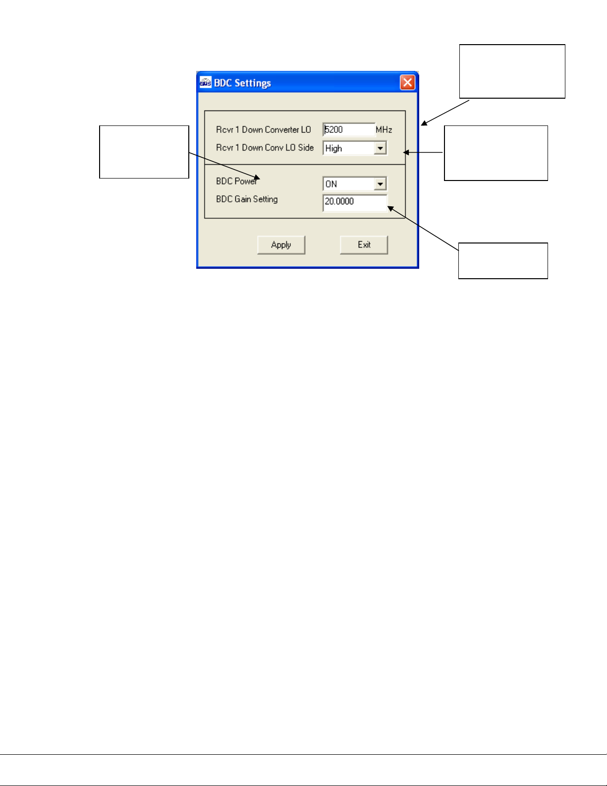
LO frequency
must be entered in
MHz.
Turns +VDC
‘ON’ or ‘OFF’
on the IF line
Choose between
High or Low side
injection
Enter gain of
the BDC
Figure 7 – BDC Settings Window
External BDC-s are connected as shown in Figure 8. Ensure to use high quality 75 ohm
impedance RF cable which can handle VHF to UHF frequencies from approximately 45 MHz to
1000 MHz. When using external BDC-s keep in mind that there is a limit to the length of the IF
cable (cable between the BDC and the VR) which is based on:
o Excessive DC voltage drop: BDC-s usually have a specification calling out a minimum
DC voltage for their units to work. Excessive cable length can cause the DC voltage to
drop below this minimum causing the system to fail. This voltage drop can usually be
calculated based on the manufacturer’s cable properties. Or you can simply measure the
DC voltage at the BDC (remember to keep a load on when making this measurement).
The bottom line is that when using ‘remote’ power the user needs to ensure the DC
voltage from the VR to the BDC is above the required minimum.
o The work-around to excessive DC voltage drop is to power up the BDC-s using ‘local’
power. Hence if the IF cable length is causing too much of a voltage drop, use a local
power supply to power up the BDC.
o Excessive IF signal loss: Excessive cable length can also cause too much signal loss
(noted in dB) before it gets to the VR. Once again the manufacturer’s cable
specifications can be used to calculate the dB loss based on frequency and cable length.
It can also be measured using a Spectrum Analyzer if one is available. Signal loss results
in system degradation noted usually in poor SNR readings and low input levels as seen
on the OSD. Remember that a 3 dB loss corresponds to half power loss!
o One possible work-around to excessive signal loss (when running long IF cable lengths) is
to use a good quality in-line amplifier. Make sure to follow manufacturer’s instructions
very closely because improper installation of an inline-amplifier could introduce other
problems.
100-M0133X1 20of33
www.cobham.com/gms
Page 21
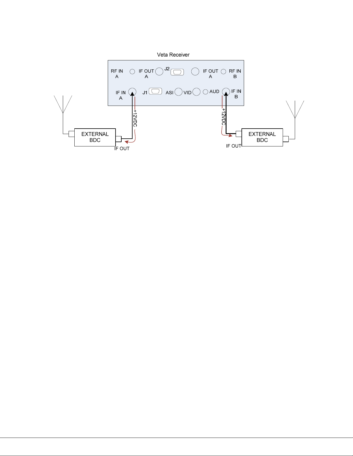
Figure 8 – External BDC Setup
100-M0133X1 21of33
www.cobham.com/gms
Page 22

6. Software Control Overview
Configuration, control and monitoring of the VR units are enabled through the use of GMS’ optional
(sold separately) MS Windows-based VR Configurator software program. This Graphical User Interface
(GUI) program provides the end user with a straightforward way to interface with the VR unit. During
normal operation, once a VDL link is established, the VR Configurator GUI can be used to monitor the
link statistics as well as control the receiver. Monitoring the link statistics is an optional operation
therefore, if desired, the VR Configurator GUI does not need to be active and can be disconnected
from the VR unit.
6.1 System Requirements
The VR Configurator program has been developed and tested on Windows 2000, Windows XP
and Windows NT. Although the VR Configurator program may work properly on other operating
systems, no GMS support or assistance can be provided concerning other operating systems.
6.2 Software Installation
The following instructions outline the installation process for the VR Configurator program:
Insert provided CD-ROM into computer.
Click on ‘setup.exe’ file. This will launch the GMS_VR Setup program and several initial setup
files will begin to be copied onto the computer.
After the initial setup files are copied over, the GMS_VR Setup program will prompt the user to
close any applications that are running. Once all other programs are exited, click on the ‘OK’
button.
The GMS_VR Setup program will prompt the user to click on the ‘computer icon’ button to begin
installation. If desired, the user can change the destination directory from the default. Click on
the ‘computer icon’ button.
The GMS_VR Setup program will then prompt the user to ‘Choose Program Group’. If desired,
the user can change the program group from the default. Click on the ‘Continue’ button.
After installing the VR Configurator program, the GMS_VR Setup program will put up a window
indicating that setup was completed successfully. Click ‘OK’.
6.3 VR Configurator Functions
The VR Configurator program provides the user access to many different configuration, control
and monitoring options. When the VR Configurator program is launched, the screen shown in
Figure 9 is displayed. The user should first select the serial port their computer is connected to
via the Serial Port Selector and Status region. If the selected serial port is valid, the gray-colored
status box will show ‘Ready’. The Device Selector region allows the end user to choose to
interface to a VR (receiver) unit. To configure a VR, select the ‘VR’ box in the Device Selector
region. Once the ‘VR’ box is selected, the screen shown in Figure 10 is displayed. The VR
100-M0133X1 22of33
www.cobham.com/gms
Page 23
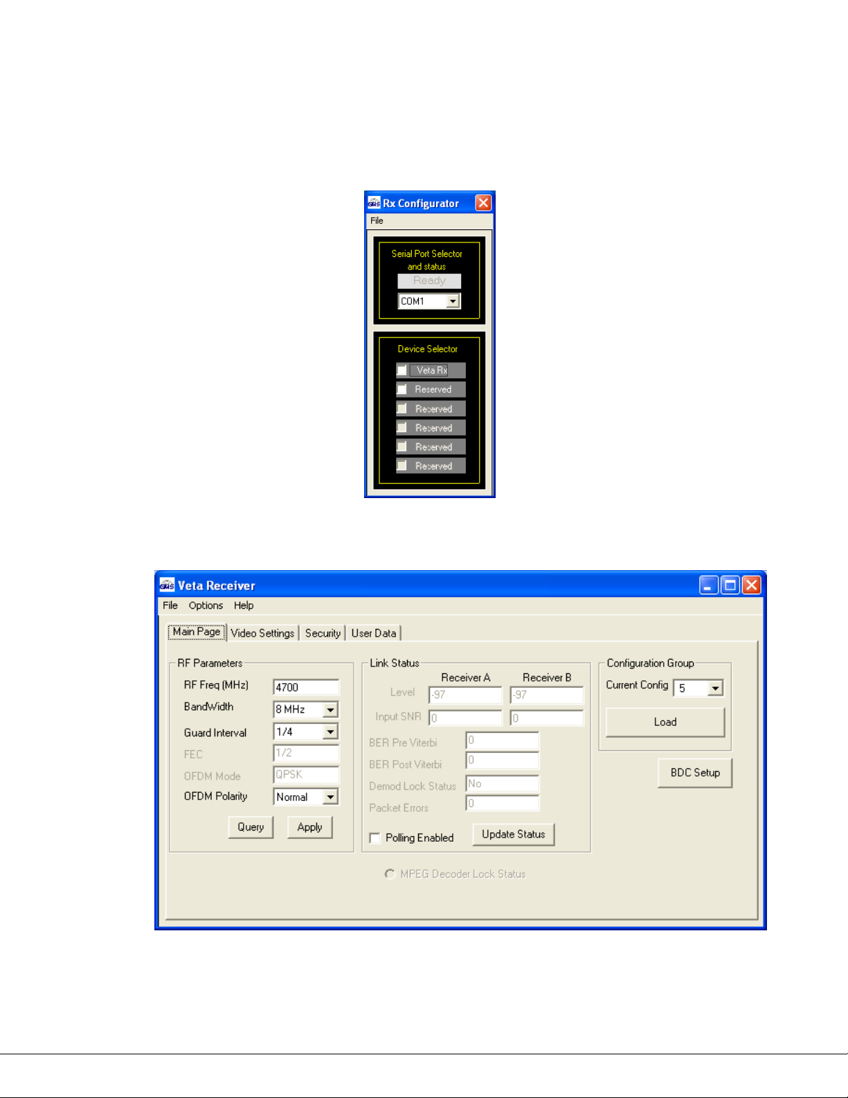
Configurator program contains function buttons and all the configurable settings available on a
VETA Rx.
For more detail see the Software Manual: 100-M0131.
Figure 9 – VR Configurator COM Port Selector
Figure 10 – VR Configurator Main Screen
100-M0133X1 23of33
www.cobham.com/gms
Page 24

7. VETA Chaining Feature
The VETA series of products use a Proprietary Transport stream protocol called ‘Chaining’ to create the
VDR (VETA Digital Repeater), the CSM (Compact Surveillance Modem) or a UDP Tx. This is all available
by utilizing the chaining feature which comes standard on all VETA Tx, VR and VNA. Contact factory
for more information about the Chaining feature and the variety of applications it can be employed
with.
7.1 VETA Digital Repeater (VDR)
An In band or cross band repeater can be made very simply with the VETA series Transmitter
(VT-2W, VT-C, or VT-L) in conjunction with a VETA Receiver. The user simply has to connect the
‘Chaining Out’ of the VR into the ‘Chaining In’ of a VETA Tx.
7.2 Compact Surveillance Modem (CSM)
The VETA Compact Surveillance Modem is much like the VDR with the addition of the VETA
NETWORK ADAPTOR (VNA). The VNA allows for IP streaming of video, or with a complement
CSM a LAN Bridge (CSB) can be created across the link.
7.3 UDP Transmitter
A UDP transmitter can easily be employed using the Chaining Out of a VNA into the Chaining In
of a VETA TX. UDP can be sent to the VNA via the RJ45 connector which is converted to
Chaining within the VNA and delivered to the VETA TX through the Chaining interface. On the
receiver Side, a VR will send its Chaining Out to the Chaining In of a VNA. The VNA can be
connected to a router or simply another computer to distribute the UDP data.
100-M0133X1 24of33
www.cobham.com/gms
Page 25

8. Specifications
8.1 C-OFDM RF INPUT
Input Ports: 2
Connectors: BNC-F
Input Impedance: 50 Ohms, <1.5:1 VSWR
Input Frequency: 0.9 to 8.5 GHz (In-Bands)
Frequency Accuracy: +/-10 ppm
8.2 C-OFDM IF INPUT
Input Ports: 2
Input Connector: BNC-F
Input Impedance: 75 Ohms, <1.5:1 VSWR
Input Frequency: 0.174 to 849 MHz
Frequency Accuracy: +/-2 ppm
Final IF Bandwidth: 10 MHz @-3dB
LO Radiation: <-25 dBm
DC Output: 12V @ 500 mA
External Down-Converters (optional)
Frequencies >845 MHz
8.3 DEMODULATION
DVB-T # of Carriers: 2k
DVB-T Bandwidth: 8/ 7/ 6 MHz
DVB-T Guard Interval: 1/32, 1/16, 1/8, 1/4
DVB-T FEC 1/2, 2/3, 3/4, 5/6, 7/8
DVB-T Modulation QPSK, 16-QAM, 64-QAM
Optional VETA Narrow BW Modes
Threshold: (6,7, & 8 MHz BW)
16-QAM ½: <-89 dBm
64-QAM ½: <-83dBm
(Optional Diversity can improve threshold by 2.5 dB)
VETA BW Threshold: -100 dBm to -105dBm
8.4 VIDEO DECODING
Compression Type: MPEG-2 (Field or Frame Encoding, Selectable) Auto Detect Desired.
Compression Standard: ISO/IEC 13818-2 with Intra-Refresh update mode
for low Latency operation
Video format standards: NTSC or PAL
VETA # of Carriers: 400
VETA Bandwidth: 2.5 MHz or 1.25 MHz
VETA Guard 1/16, 1/8
VETA FEC 1/3, 2/3
VETA Modulation QPSK, 16QAM
QPSK ½: <-95 dBm
100-M0133X1 25of33
www.cobham.com/gms
Page 26

Profiles: SP@ML or MP@ML
Chroma Format: 4:2:0 or 4:2:2
Line Standard: 525 and 625 (NTSC/PAL)
Horizontal Resolution: 704, 528, 480, 352 pixels
Veta Systems Latency end to end delay: Down to ~44ms for 6,7, or 8 MHz,
Narrow BW to ~120mS (w/VETA TX Only, mode dependant)
Video Outputs
1- Composite w/OSD, 1-S-Video
Standards: NTSC (with and without pedestal) or PAL
Video Connectors: Composite – BNC-F,
S-Video – p/o J-1, DB-15F
Output Impedance: 75 Ohms
Output Level: 1V p-p
Frequency Response: 10 Hz to 4 MHz, +/- 1.5 dB
8.5 AUDIO DECODING
Number of Channels: 2
Decompression Type: MPEG Layer I & II (Musicam) or NICAM (User Selectable)
Musicam
Compression Standard: ISO/IEC 13818-3(Musicam)
Bit rates: 256 kbit/s/ch (Musicam) All bitrates supported
Sampling Frequency: 48 kHz only (Musicam)
Nicam (Ultra-Low Latency)
Bits per Sample: 12 or 8
Sampling Frequency: 32 KHz, 16 KHz or 8 KHz
Frequency Response: 200 Hz to 10 KHz, +/- 1.0 dB Analogue
Audio Outputs: Un-balanced outputs, Line Level
Output Impedance: <100 Ohms Unbalanced
Connector: LEMO 5 pin
8.6 POWER
DC Voltage Range: 9 - 18 V
Reverse Voltage Protection
Power Consumption: 12 Watts
W/ Optional AC to DC Adapter
AC Voltage: 90-264 VAC @ 45-440 Hz
AC Power Consumption: 13 Watts
Circuit Breaker Protector
8.7 Physical
Less Handles
Dimensions: 9.752” W x 4.8” D x 1.754” H
24.77 cm W x 12.19 cm D x 4.45 cm H
With Handles
Dimensions: 9.752” W x 6.8” D x 1.754” H
24.77 cm W x 17.27 cm D x 4.45 cm H
Weight: 3.69 lbs (1.67 kg)
100-M0133X1 26of33
www.cobham.com/gms
Page 27

8.8 Environmental
Operational Temperature: -10 to +70 deg C
8.9 Optional LAN/USB Interface
Refer to GMS’ VETA IP Network Adapter (VNA) Data Sheet.
This optional module provides 10/100 Base-T LAN (RJ-45) Interface
that can be used for audio/video/user-data streaming
8.10 RS232 DATA OUTPUT
Baud Rate: Up to 115 k baud.
Connector: p/o J1, DB-9M
8.11 CONTROL
Local Control: Front Panel with 16 channel/mode select,
Preset key selection (1-16).
8.12 REMOTE CONTROL
RS232 Control from PC GUI: All receiver options and functions are controlled via
the remote interface.
8.13 LOCAL MONITORING
Control Panel: Signal Strength (Bar Graph), Channel & Mode, and Rx Lock, invalid
Encryption Key
OSD: Signal to Noise Ratio (SNR), Pre and Post FEC Bit Error Rate (BER) and Packet
Errors.
8.14 REMOTE MONITORING
All RX measurements and controls
8.15 SECURITY OPTION
ABS is standard. The VR can optionally be provided with BCRYPT 128 or 256 for
protecting the signal in sensitive applications.
100-M0133X1 27of33
www.cobham.com/gms
Page 28

Appendix A – LED Indictors
LED condition Meaning Action
No Config LED-s lit
Config LED is
flashing
Red Alarm Lit
RF LED Off
Red Alarm Lit
RF LED On
Signal strength
LED-s off
Unit is OFF
Indicates that BDC
power is off
Turn the unit On
Push the Mode button to
turn BDC-s On.
Ensure that RF source is
active and has correct
frequency.
No RF Signal Lock
Ensure that BDC-s are
turned on.
Ensure there is no
interfering signal
Ensure that Video is enabled
Has RF Signal Lock, but
no decoder Lock
at the Transmitter.
Ensure that scrambling keys
matched
No incoming RF signal Ensure that RF source is
active.
100-M0133X1 28of33
www.cobham.com/gms
Page 29

Appendix B – Troubleshooting Section
Symptom Possible Reason Action
Interference.
Receive antenna
positioning.
Poor Link
performance
Poor alignment of
directional antennas.
Unsuitable Antennas.
Reduced Transmit Power.
Reduced
Horizontal Resolution.
image
quality
Video Bit Rate.
SNR
Reading: 0.0
but, other
RF
OFDM Polarity Mismatch
parameters
locked
Remove interfering signal or
switch to alternative
frequency.
Where possible mount
antennas unobstructed, away
from other objects and as high
as possible.
Ensure a proper alignment.
Ensure that antennas are in a
right band.
Ensure that attenuation setting
is appropriate for direct output
or amplifiers connected.
Select horizontal resolution
that matches the resolution of
the source.
Ensure appropriate Audio
mode is selected or fully
disabled if not required.
Either on the Tx or Rx (which
ever is more accessible) switch
the OFDM polarity
100-M0133X1 29of33
www.cobham.com/gms
Page 30
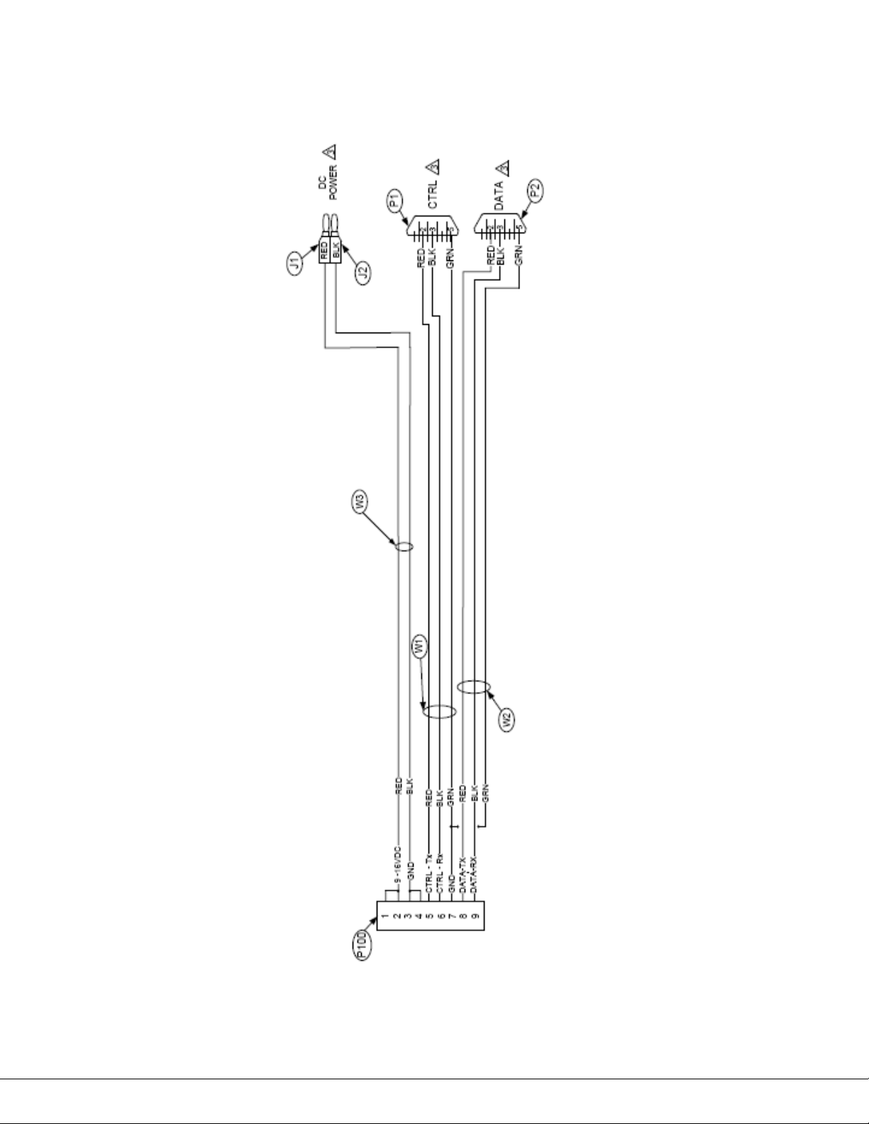
Appendix C – Control Cable
100-M0133X1 30of33
www.cobham.com/gms
Page 31
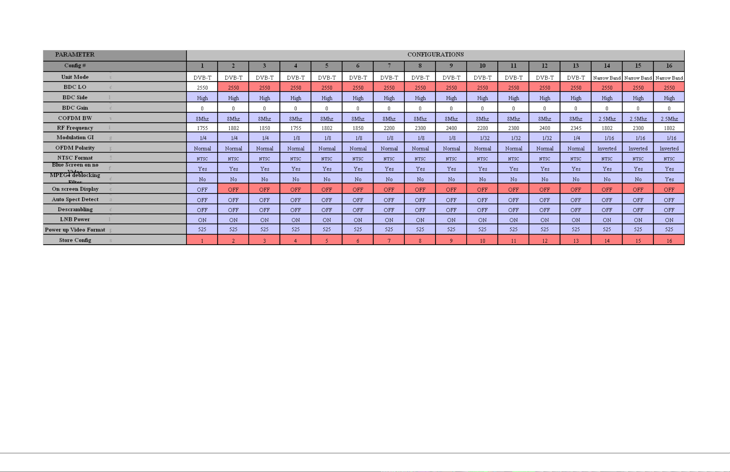
Appendix D – VR DEFAULTS, LS BAND
The most important thing we build is trust.
100-M0133X1
www.cobham.com/gms
31of33
Page 32
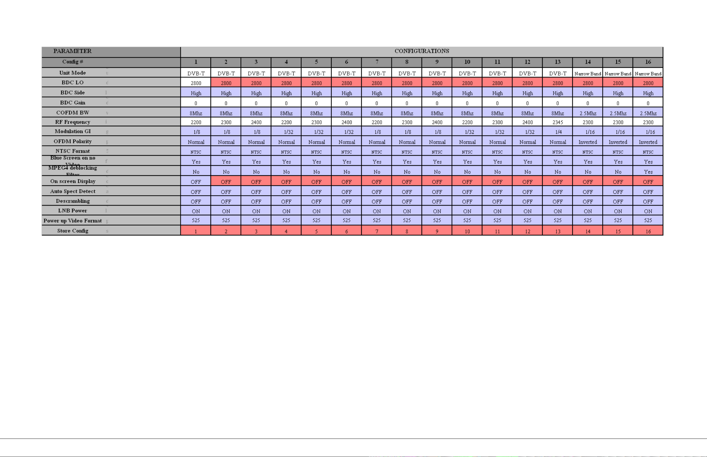
Appendix E – VR DEFAULTS, S1 BAND
100-M0133X1 32of33
www.cobham.com/gms
Page 33
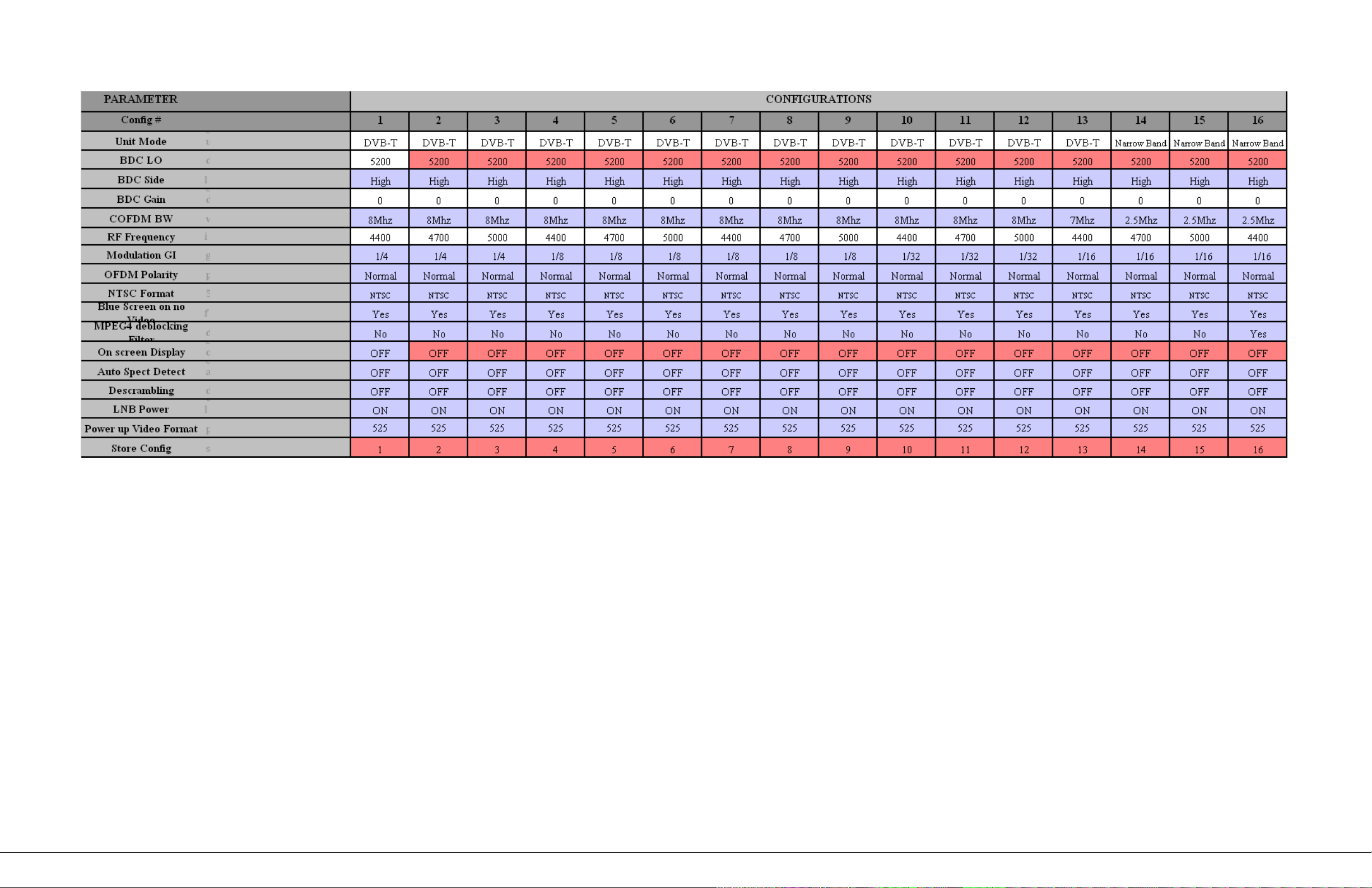
Appendix F – VR DEFAULTS, C2 BAND
100-M0133X1 33of33
www.cobham.com/gms
 Loading...