

Page 1
B36
GÖÇMAKSAN
GÖÇMAKSAN
Rev:01/2013
Page 2

B36
1
CONTENTS
CONTENTS .............................................................................................................................................. 1
LIST OF FIGURES .................................................................................................................................. 2
TAGS USED ON THE MACHINE.......................................................................................................... 3
INTRODUCTION .................................................................................................................................... 4
1. MAIN PARTS OF BENDING MACHINE ......................................................................................... 4
2. MACHINE ASSEMBLY ...................................................................................................................... 5
3. MACHINE RUNNING PROCEDURES ORDER ............................................................................... 6
4. TECHNICAL DATA ............................................................................................................................ 7
5. EQUIPMENT SUPPLIED WITH MACHINE ..................................................................................... 7
6. USING THE MACHINE .................................................................................................................... 8
6.1 Correct Connection of the Irons on the machine ............................................................................ 8
6.2. Incorrect placement of the irons to bu bent on the machine .......................................................... 8
6.3. Incorrect placement of the irons to be bent on the machine .......................................................... 9
7. PROHIBITED USAGE ON THE MACHINE ................................................................................... 10
8. SCOPE OF THE WARRANTY ......................................................................................................... 11
9. PROTECTORS TO BE USED WHEN WORKING WITH THE MACHINE .................................. 11
9.1. Protector apparel .......................................................................................................................... 11
9.2. Work clothes ................................................................................................................................ 12
10. HANDLING THE MACHINE ......................................................................................................... 12
11. CONTROLS AND SETTINGS ON THE MACHINE ..................................................................... 13
11.1. Thermal flow setting range and motor protection switch .......................................................... 14
11.2. Bent Bar Bending setting (45°) .................................................................................................. 15
11.3. Protractor Bending Setting (90°) ............................................................................................... 16
11.4. Hook Bending Settings (180°) ................................................................................................... 17
11.5. Stirrup Bending: ......................................................................................................................... 17
12. MAINTENANCE AND LUBRICATION INSTRUCTIONS .......................................................... 20
10. FAULTS AND SOLUTION OFFERS ............................................................................................. 20
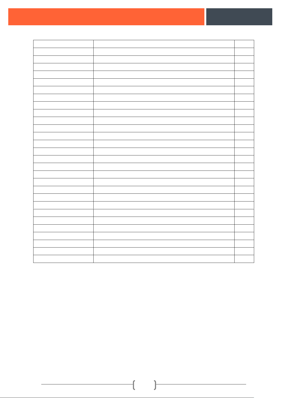
14. MACHINE EQUIPMENT LIST ...................................................................................................... 23
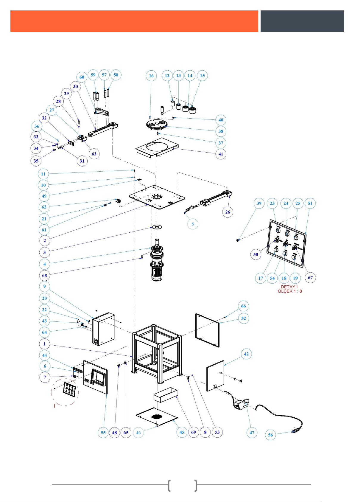
15. MACHINE ASSEMBLY .................................................................................................................. 25
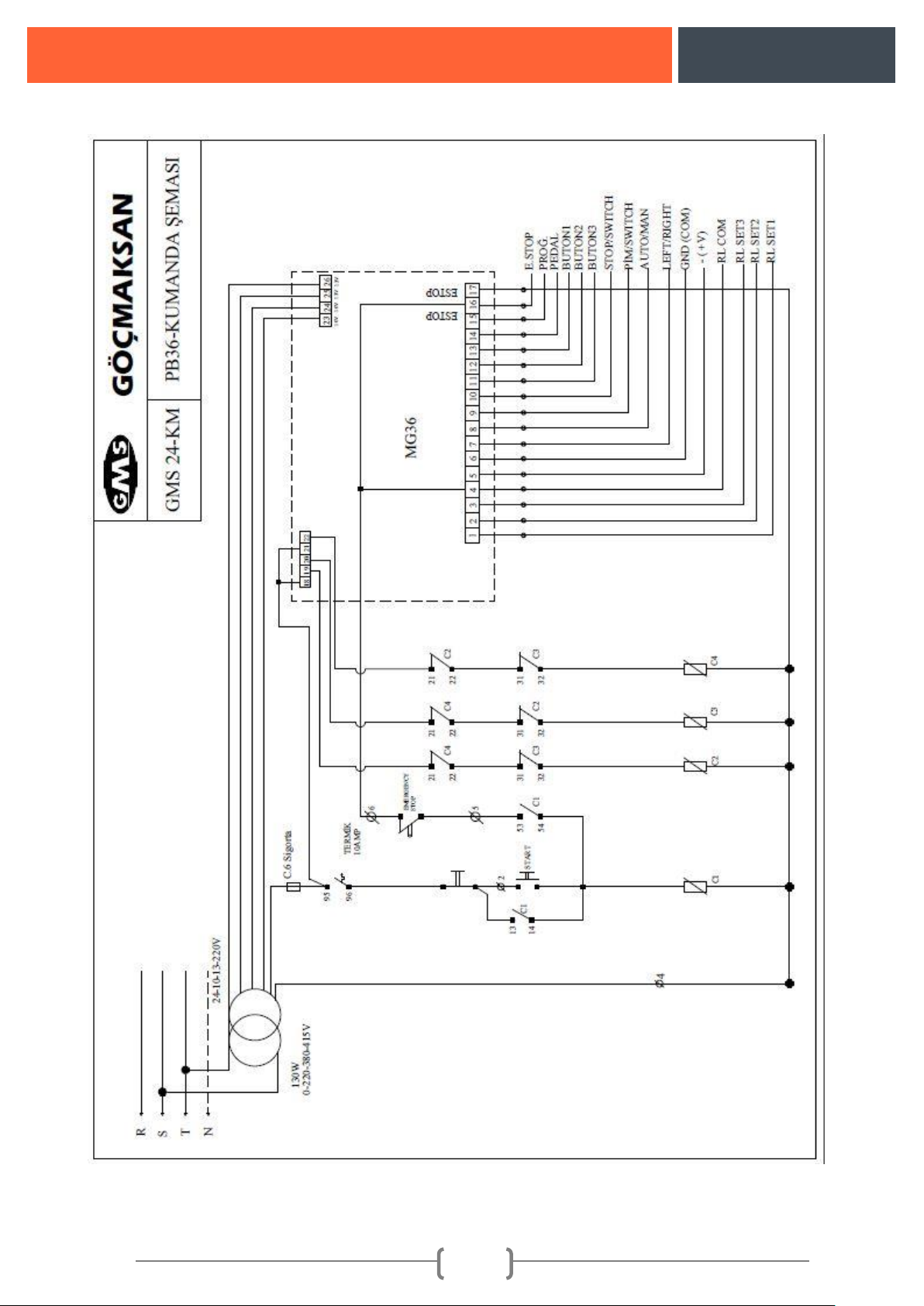
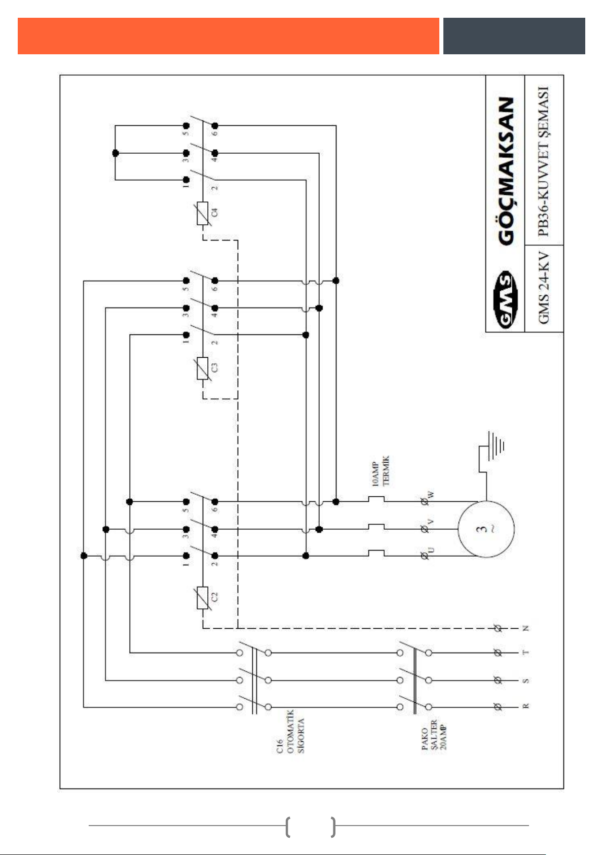
16. MACHINE ELECTRICITY SCHEME ............................................................................................ 26
17. ABOUT COMPANY ........................................................................................................................ 28
Page 3

B36
2
LIST OF FIGURES
Figure 1: Main parts of bending machine ................................................................................................. 4
Figure 2: Leveling the machine on a solid ground .................................................................................... 5
Figure 3: Control buttons .......................................................................................................................... 6
Figure 4: Placing the irons on the machine correctly ................................................................................ 8
Figure 5: Incorrect connection of the irons on the machine ..................................................................... 9
Figure 6: Wrong placement of the irons on the machine ........................................................................ 10
Figure 7: Wrong positioning of the person making bend ....................................................................... 10
Figure 8: Handling the machine .............................................................................................................. 13
Figure 9: Machine control panel and functions ...................................................................................... 13
Figure10: Bent bar bending indicator ..................................................................................................... 16
Figure 11:Representation of Protector Bending...................................................................................... 16
Figure12: Hook Bending demo ............................................................................................................... 17
Figure13: Stirrup bending demo ............................................................................................................. 19
Page 4
B36
3
MAIN SAFETY INFORMATION
➢ This symbol is put before the articles giving warning explanations in order to draw attention of the
trained operator to important functions.
€ This symbol is put before the articles giving warning explanations in order to draw attention of the
trained operator to electrical issues.
This symbol is put before the sentences in order to draw attention of the trained operator to the
master instructions and directive regarding to handling or safety.
TAGS USED ON THE MACHINE
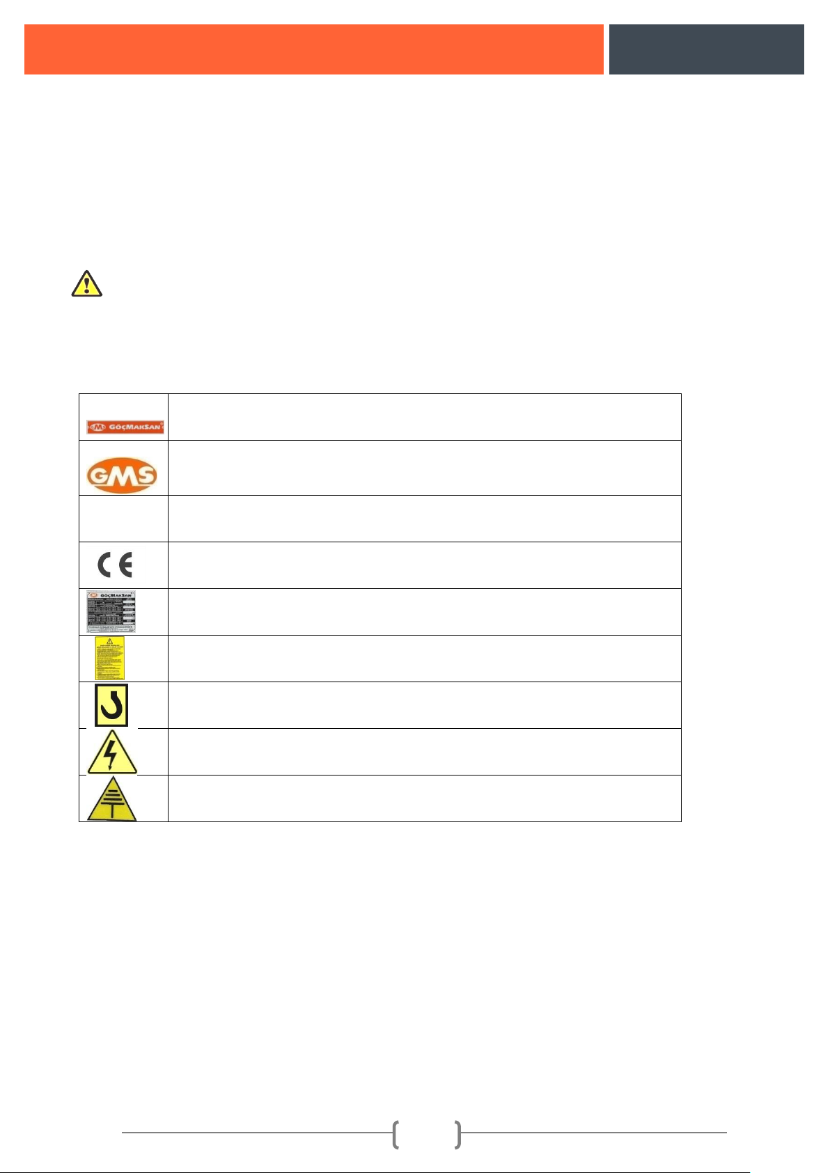
Trademark plate of manufacturer company
Logo plate of manufacturer company
B 36
Model name tag of the machine
CE norm conformity tag
Plate on capacity and technical information of the machine
Machine user's and maintenance manual tag
Handling and carrying hook tag
Electricity panel warning tag
Grounding output tag
Page 5
B36
4
INTRODUCTION
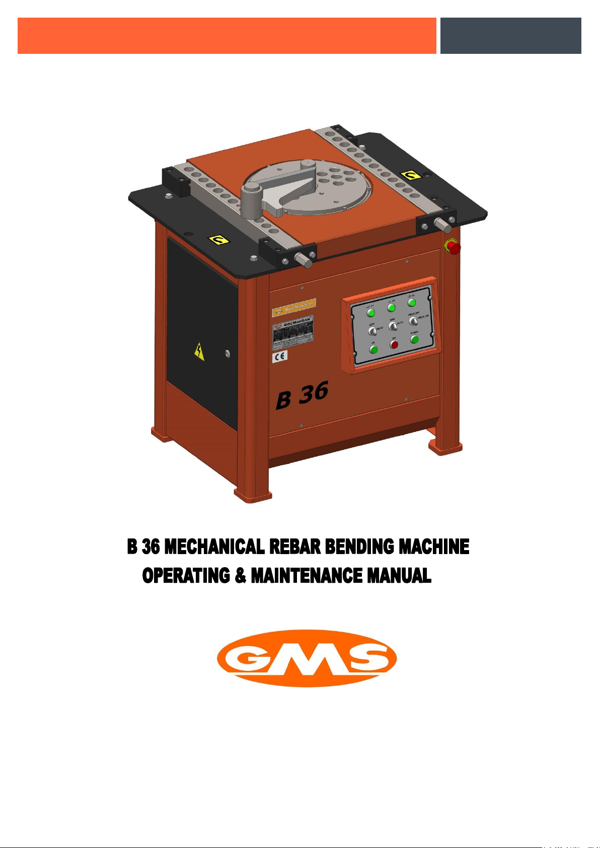
B 36 Mechanic Iron Bending Machine is made only with the purpose of steel material bending.
Using other than the indicated purposes are prohibited. It is possible to mount various apparatuses on
the machine optionally for bending in different shapes.
In order to obtain the best yield from the machine it should be in a situation so that it can be worked
easily and in a position that more productivity might be obtained from the operator. Because of this the
location where the machine is operated should be close to the iron stocks. Besides, it shall be more
useful to cover top of the location where the machine is operated with a shelter. We suggest two
workbenches to be located on two sides of the machine. Length of these workbenches should be as
long as the longest iron that will be bent. Since the operator will be able to work without turning,
lifting any kind of iron, it will enable the operator to work more effectively.
Important Warning !!!
• User's and maintenance manuals must be read.
• Machine should be operated by instructed workers.
• When adjustments such as controlling, maintaining, lubing are being made electricity of the
machine must be cut off.
• All of the explanations given under user's and maintenance manual must be complied.
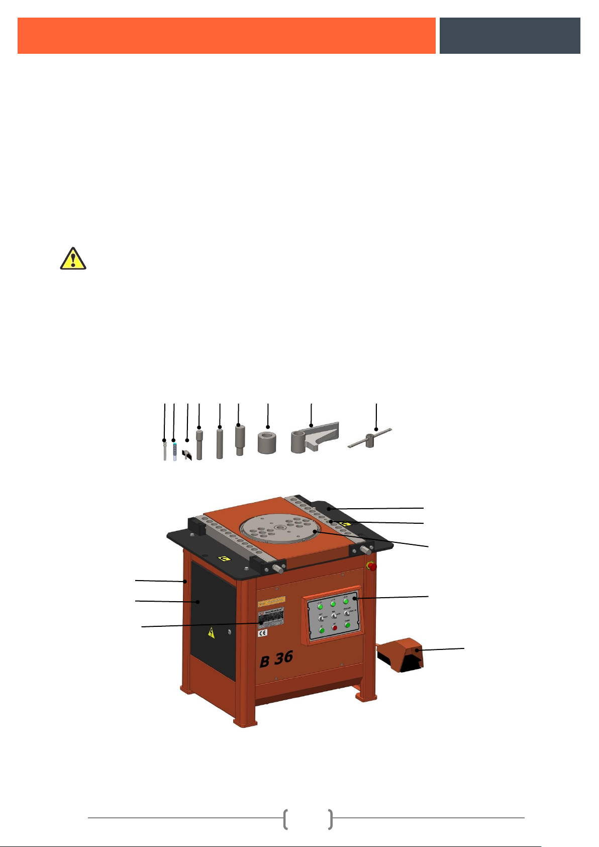
1. MAIN PARTS OF BENDING MACHINE
Figure 1: Main parts of bending machine
3 4 5 6 7 8 9
10
11
1 2 17
15
12
13
14
16
Page 6
B36
5
1
Machine Frame
5
Zero Adjustment
Pin
9
Bending Sleeve
13
Bending Plates
2
Electricity Board Cap
6
Stirrup Pin
10
Retainer
14
Bending Flange
3
Switch Adjustment
Pin
7
Straight Pin
11
Adjustment
spanner
15
Control Panel
4
Sensor Pin
8
Bending Pin
12
Machine Table
16
Foot Pedal
17
Plate
2. MACHINE ASSEMBLY
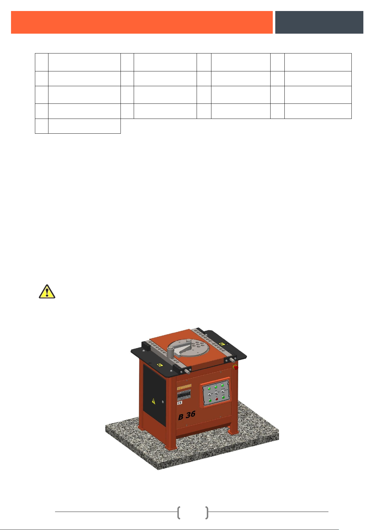
• Machine should be leveled on a solid ground. Figure 2
• Electricity connection of the machine should be made by competent technicians.
Explanation
Electricity Connection
For main electricity connection plug should be connected to supply line with a 5x4 mm²
isolated cable and then plugged into power outlet.
Grounding connection should be made for safety. Machine shouldn't be operated without
making grounding connection.
Connection of grounding line
The following procedures should be followed for this system.
Connect one end of the grounding to a copper wire (minimum 16 mm²) as it will enable
electrical conductivity. The other end should be either connected with a pipe that has a conductivity
capacity immerged into the ground (preferably into a humid ground) or the copper plate should be
buried into the ground as much as deep.
Figure 2: Leveling the machine on a solid ground
Page 7
B36
6
3. MACHINE RUNNING PROCEDURES ORDER
• Be sure that the machine is assembled in conformance with the Machine Assembly procedures.
• If there is any object on the machine (including the bending apparatus) they must be removed.
• LEFT-RIGHT switch on the control panel of the machine is turned to LEFT or RIGHT position,
MAN AUTO switch is turned to MAN position and machine turning direction is confirmed by
pressing on the foot pedal.
Explanation: Rotation direction is approved by taking the front of the machine as reference (Control
pane side) the clockwise as right and counter-clockwise as left. If the machine is rotating reverse of the
switch it means phases of the electricity supply are feeding reversely. This situation doesn't affect the
running system of the machine. In such case LEFT-RIGHT switch might be turned to the other side or
competent electricians might change the directions of the phases.
After fixing the direction of rotation bending adjustments should start.
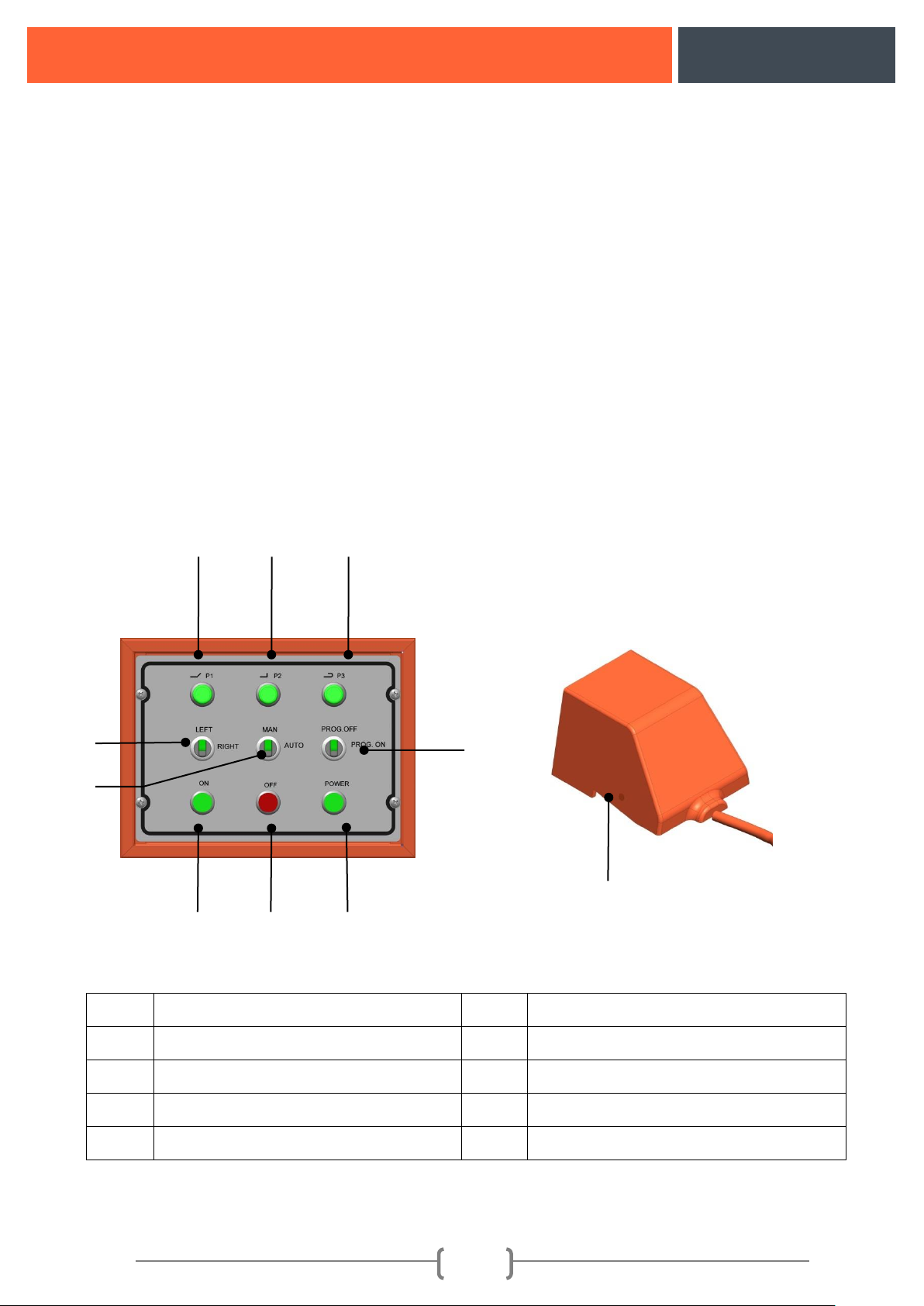
Control buttons
Figure 3: Control buttons
1
P1 Button
6
Program On-Off Switch
2
P2 Button
7
On Button
3
P3 Button
8
Off Button
4
Left-Right Switch
9
Power Button
5
Man-Auto Switch
10
Foot Pedal
1 6 7 8 9
10 5 2 3 4
Page 8
B36
7
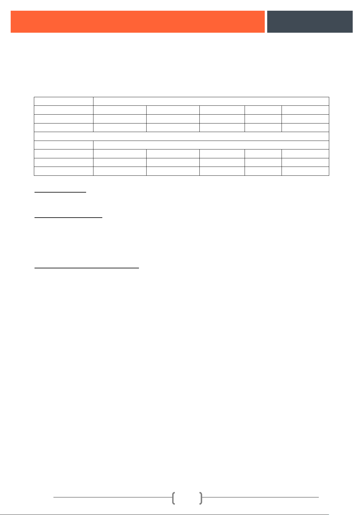
4. TECHNICAL DATA
Machine Bending Capacity:
Steel Quality
Diameter/Bending Capacity
45 kg/mm²
Ø 36x1
Ø 18x2
Ø14x2
Ø9x4
Ø6x6
65 kg/mm²
Ø 28x1
Ø 16x2
Ø14x2
Ø9x3
Ø6x4
85 kg/mm²
Ø 26x1
Ø 12x2
Ø9x2
Ø9x3
Ø4x6
Steel Quality
Diameter/Bending Capacity
45 kg/mm²
Ø 36x1
Ø 18x2
Ø14x2
Ø9x4
Ø6x6
65 kg/mm²
Ø 28x1
Ø 16x2
Ø14x2
Ø9x3
Ø6x4
85 kg/mm²
Ø 26x1
Ø 12x2
Ø9x2
Ø9x3
Ø4x6
Machine Model: B 36
Machine Name: Mechanical Iron Bending Machine
Machine Dimensions:
Width : 81 Cm
Length : 92 Cm
Height: 85 Cm
Weight : 407 Kg
Specifications of the Motor Used:
Motor power : 3 kW
Motor RPM : 1400 rpm
Motor Voltage : 380 V
Frequency : 50 Hz
5. EQUIPMENT SUPPLIED WITH MACHINE
• Pin: 5 Pieces
• Stirrup Pin : 1 Piece
• Straight Pin : 1 Piece
• Bending Sleeve 5 Pieces
• Adjustment spanner 1 Piece
• SWITCH pin 6 pieces
• Retainer : 1 Piece
Page 9

B36
8
6. USING THE MACHINE
6.1 Correct Connection of the Irons on the machine
Fixing the iron to be bent on the
machine with the help of retainer
(4a)
Fixing the iron to be bent on the
machine with the help of bending
sleeves.(4b)
Fixing the irons to be bent on the
machine with the help of retainer in
multi-iron bending (4c)
Fixing the irons to be bent on the
machine with the help of bending
sleeves in multi-iron bending (4d)
Figure 4: Placing the irons on the machine correctly
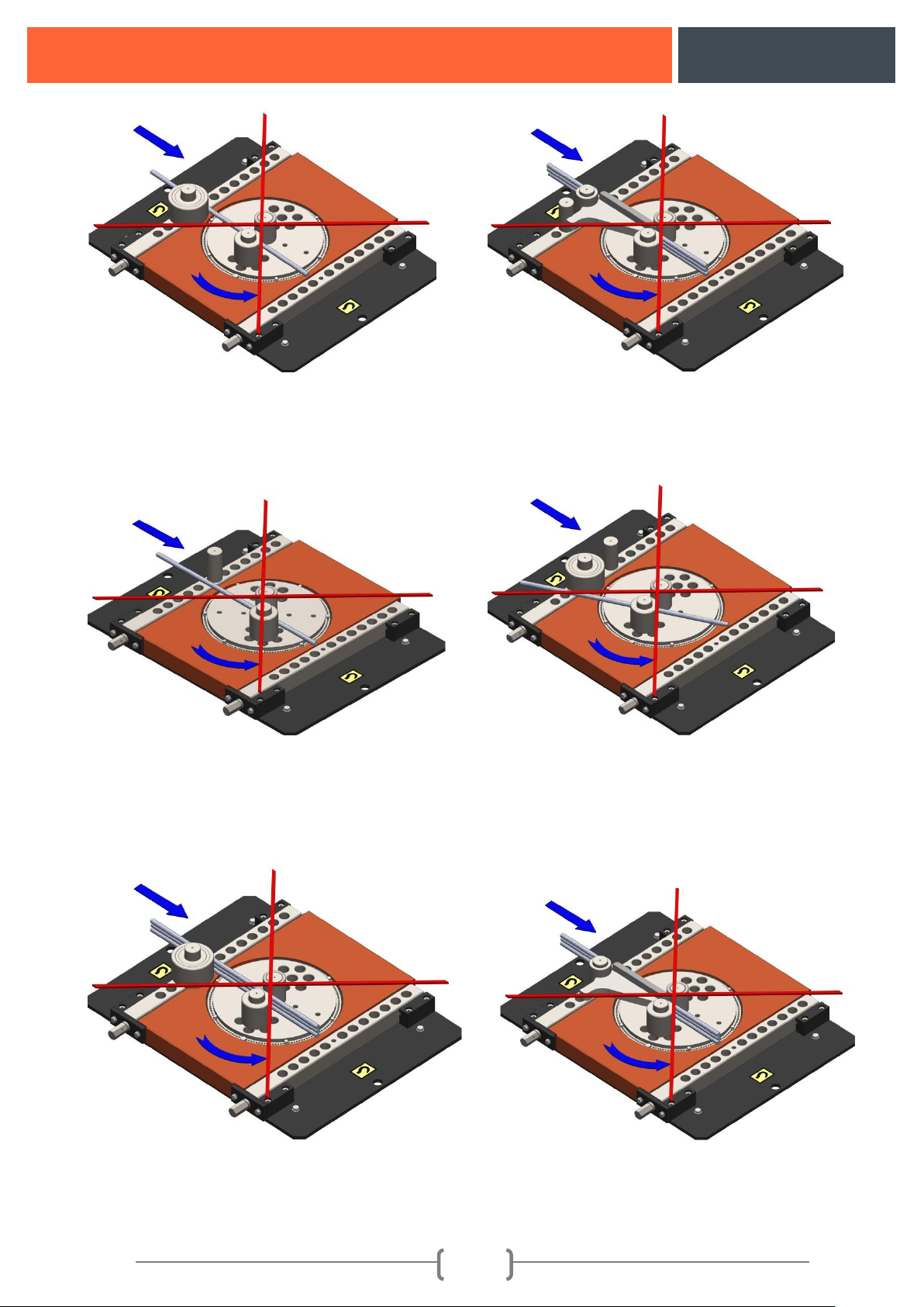
6.2. Incorrect placement of the irons to be bent on the machine
Incorrect placement of a single iron
to be bent with bending sleeves
(5a)
Incorrect placement of a single iron to
be bent with retainer (5b)
(4a)
(4b)
(4c)
(4d)
Page 10
B36
9
Figure 5: Incorrect connection of the irons on the machine
6.3. Incorrect placement of the irons to be bent on the machine
Incorrect connection of multi-irons
to be bent on the machine with
bending sleeves
Incorrect connection of multi-irons to be
bent on the machine with retainer
(5a)
(5b)
(6a)
(6b)
(6c)
Page 11
B36
10
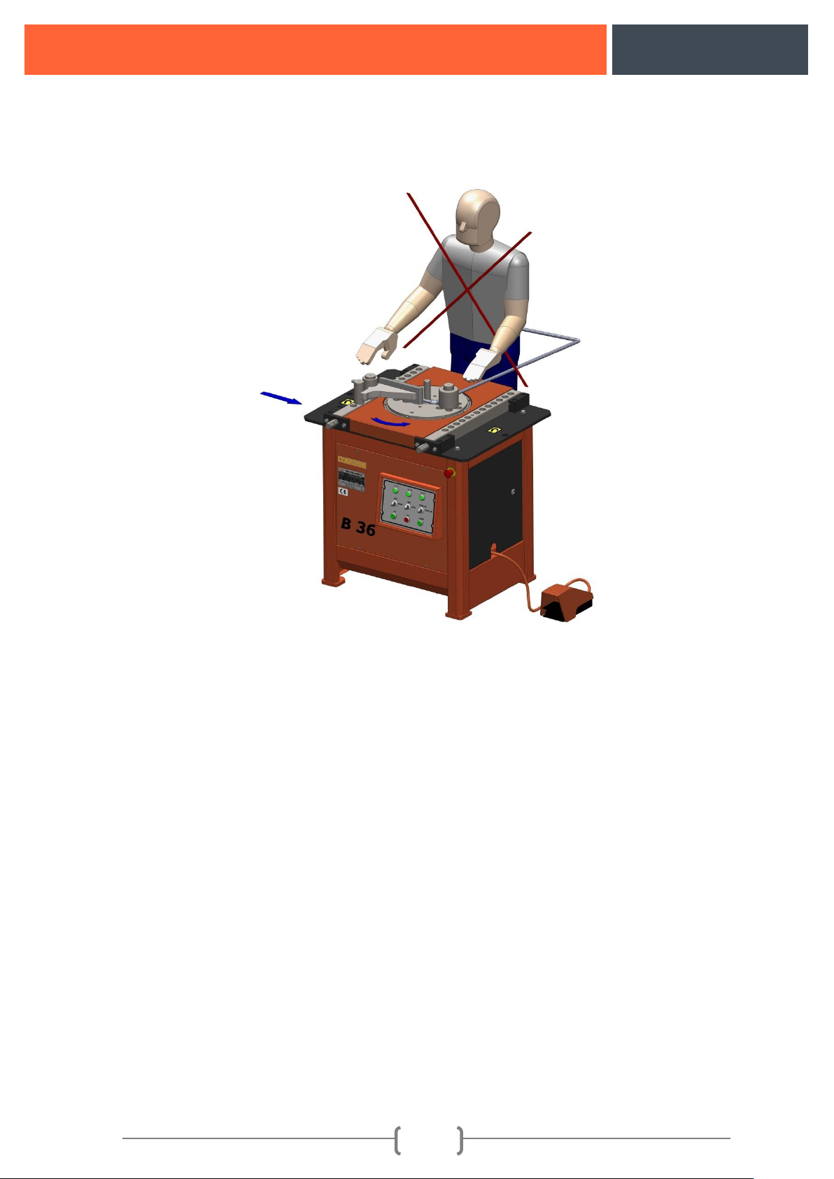
Figure 6: Wrong placement of the irons on the machine
Figure 7: Wrong positioning of the person making bend
7. PROHIBITED USAGE ON THE MACHINE
➢ When bending no one must stand in front of the machine and any one standing must be taken away.
(Figure 7)
➢ While the machine is running no any other construction material such as adze, hammer, meter,
caliper etc. should be put between the bending apparatus other than the material that will be bent.
➢ Machine mustn't be run when it is wet.
➢ No any bending must be made other than the measurements, dimensions and units stated on the
capacity plate (Figure 1-16).
➢ During the multi bending number of irons stated on the capacity plate should be aligned one on top
of the other and should be leaned to the retainer or bending rollers. No any other bending should be
made other than this. (Figure 6c-6d)
€ Machine mustn't be run when the electricity Board Cap (Figure 1-2) is open.
€ Electrical settings made in the factory shouldn't be changed.
€ Machine shouldn't be operated without making grounding connection.
➢ Machine shouldn't be operated when the housing covers are dismantled.
➢ Machine should be operated by instructed workers.
➢ Machine never should be run unlubricated.
➢ Warning plates attached on the machine mustn't be removed.
(6d)
Page 12

B36
11
➢ No other parts should be mounted to the machine other than the ones manufactured by Göçmaksan
company.
➢ No bending should be made on the machine with bending apparatus which are deformed, cracked or
have an increased hole diameter.
➢ No wrong bending should be made on the machine. (Figure 5a-5b-6a-6b-6c-6d)
➢ Machine should be cleaned by air.
€ In cases when electricity board cap should be opened, the cap mustn't be opened without cutting the
power of the machine from the main switch.
➢ Irons to be bent should be fixed on the machine correctly. Fixing with retainer bending sleeve and
pins (Figure: 4a-4b-4c-4d).
8. SCOPE OF THE WARRANTY
Manufacturer acknowledges warranty and liability provided that complying with the following
conditions.
➢ Protectors found on the machine should be used.
➢ Warning signs should be taken into account.
➢ Machine shouldn't be operated without making grounding connection.
➢ Parts manufactured by Göçmaksan Company should be used in case it is required to replace a
broken part.
➢ Conditions indicated under the safety measures should be taken into account.
➢ Prohibited usage should be taken into account.
➢ Machine should be assembled in conformance with the assembly conditions.
➢ Machine should be handled in conformance with the handling conditions.
➢ Machine should be used by informed and authorized person.
➢ Measurements, dimensions and steel quality stated on the capacity plate should be taken into
account.
➢ Machine should be used in conformance with its manufacturing purpose.
➢ Electricity connection should be made by competent technicians.
➢ Machine shouldn't be used with any of the parts on it disassembled.
➢ Motor of the machine shouldn't be changed.
➢ Maintenance of the machine should be made in conformance with the maintenance conditions.
➢ No iron higher than the indicated size should be bent with retainer (maximum 16 mm)
➢ Correct bending should be made with the machine.
9. PROTECTORS TO BE USED WHEN WORKING WITH THE MACHINE
9.1. Protector apparel
➢ Helmet must be worn.
➢ Glasses must be worn.
➢ Boots with steel toe must be put on.
➢ Gloves must be worn.
Page 13
B36
12
The aforementioned protectors will be used. In case of not using these apparels there are risks of
injury, cutting and trapping hands.
9.2. Work clothes
Inappropriate clothes against snatch or grip while working with the machine are listed below and
in case of not conforming to this list might cause risk of injury.
Long hair, dress with long arms, bracelet, uniform with long skirt, any ornament leaning out.
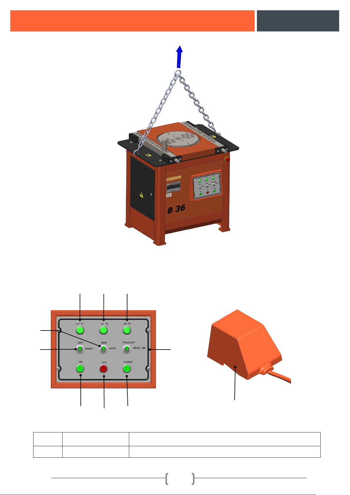
10. HANDLING THE MACHINE
In order to carry the machine forklift, mobile crane or a hoist should be used. When lifting the
machine steel cable, chain or fiber sling should be used. When lifting out of the chest lifting lugs on
the machine should be used. During the lifting operations experienced expert staff and subcontractors
should be assigned.
WARNING!!!
Machine should be moved without any vibration. Machine shouldn't be run in a wet environment.
If there are any lost or damaged parts during the handling, they should be reported to the manufacturer.
• When using the lifting and carrying equipment their maximum loading capacities should be taken
into consideration.
• During the lifting equipment's center of gravity should be taken into consideration.
WARNING!!! Warning signs on the carrier equipment should be taken into consideration.
Page 14
B36
13
Figure 8: Handling the machine
11. CONTROLS AND SETTINGS ON THE MACHINE
Figure 9: Machine control panel and functions
NO
BUTTON
FUNCTION
1
P1
It ensures settings for bent bar bending
6
10 4 7 8 9
5
1 2 3
Page 15
B36
14
2
P2
It ensures settings for protector bending
3
P3
It ensures settings for hook bending
4
Left-Right
It changes machine's rotation direction to left or right.
5
Man-Auto
It provides machine to be controlled automatically and manually.
6
Program OFF
Machine operates in normal mode. The bending is made
according to the preferred angle.
6
Program On
Programming Mode of the Machine
7
ON
It provides machine system to engage.
8
OFF
It ensures switching the machine system off.
9
Power Lamp
It indicates that there is electricity on the system when electricity
is supplied to the system when ON button is pressed.
10
Foot Pedal
It ensures rotation of bending flange.
11.1. Thermal flow setting range and motor protection switch
For a motor of 1.5 kW 1440 rpm it is set 5 A by machine manufacturer. It is not appropriate for
user to change settings. Motor protection switch is mounted to the machine in order to prevent damage
on the system by cutting the electricity current when excessive current is drawn by the system. If the
switch is tripped switch should be turned on by turning the button to position 1. Motor protection
switch should never be disassembled.
Page 16
B36
15
11.2. Bent Bar Bending setting (45°):
Prog. Off Normal Bending Setting Systems:
Before starting angle setting, it should be ensured that there is no any material on the machine
other than the bending equipment.
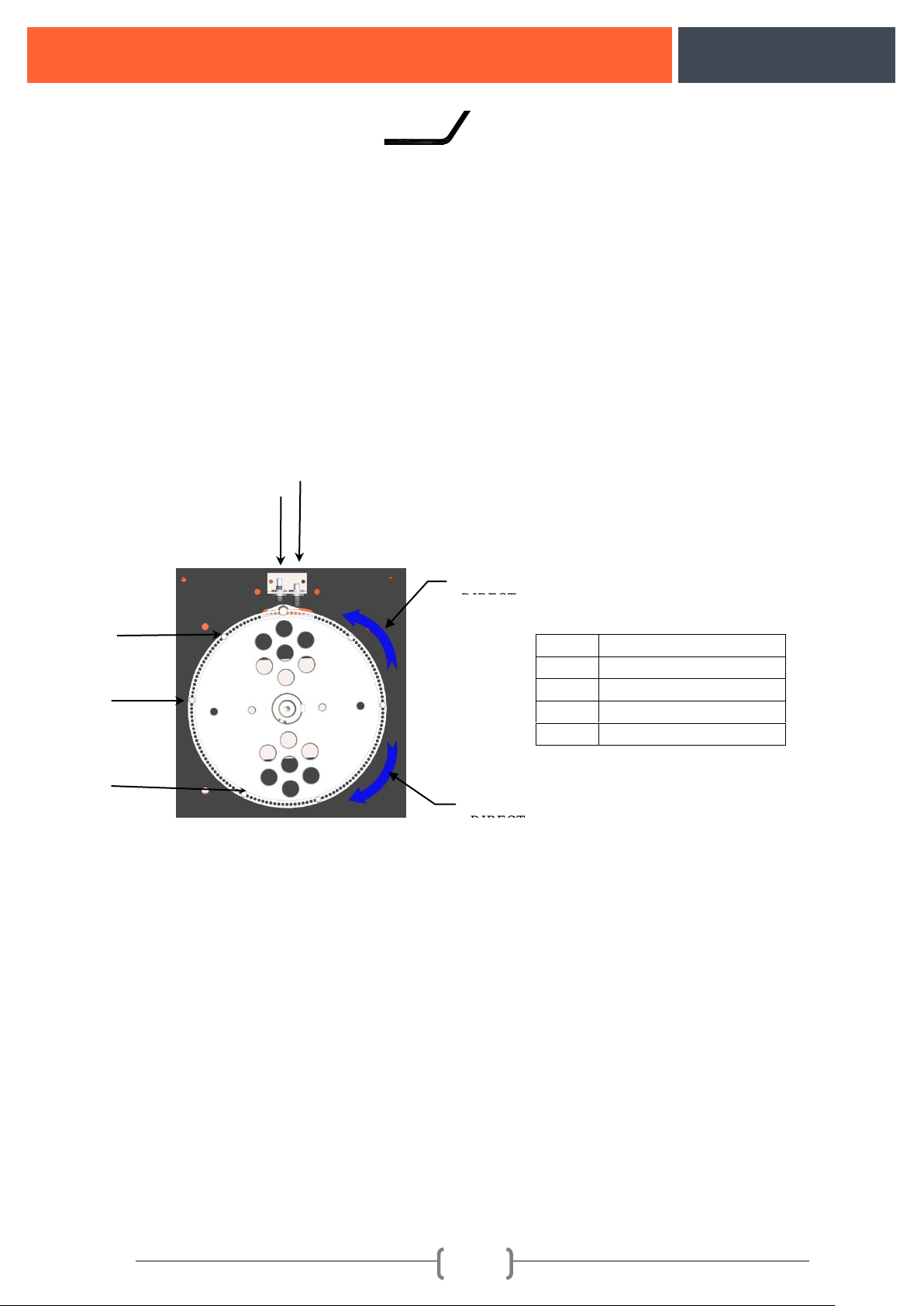
The Switch button should be taken to OFF position and P1 button should be pressed. There are
3 Switch Pins with same heights on the bending disc. Rotation direction should be controlled by taking
the machine to MAN position. Appropriate bending angle for venting should be set by trying the
switch pin (P1) (Figure 1-3) throughout the holes on the bending disc (A and B directions). As long as
the switch pins (A and B) are taken closer to the measurement sensor (Figure 1-4) from both sides, the
bending angle decreases. Conversely as they are taken away from the measurement sensor the bending
angle increases.
NOTE: For P1 button Switch pin=1; For P2 button Switch pin=2; For P3 button Switch pin=3 are used
to set the angle.
After the setting procedure is completed the iron for bending and bending equipment must be
put on the machine and it should be available for bending as it is shown in Figure 4a-4b-4c-4d . It
should be mounted according to the diameter (if it is smaller than 16 mm the retainer and if it is bigger
than 16 mm the appropriate bending sleeve) of the iron to be bent (Figures 4a-4b-4c-4d). Lastly when
the bending disc returns after bending the iron it should be mounted on the bending plate on the front
side of the iron for safety to prevent any injury due to movement of the iron. (Figure 10). Setting
process should be completed by ensuring the iron to be bent (Figures 4a-4b-4c-4d) positioned parallel
by moving bending plates backward and forward with the help of the adjustment spanner. (Figures 4a-
4b-4c-4d)
For serial bending, machine should be taken to AUTO position and then bending should be
made.
NOTE: When the machine is at the MAN position the bending disk revolves, after bending is
completed and the machine is on the holding position it stops. When the machine is at the AUTO
position bending disk stops at holding position by completing the bending just pressing the Foot Pedal
only once. When the machine is at the AUTO position, the machine can be stopped by pressing the
1
Switch pin =P1
2
Switch pin =P2
3
Switch pin =P3
4
Measurement Switch
5
Stop Switch
5
1 2 3
4
B
A
Page 17
B36
16
foot pedal as the bending process is started. The stopped machine might be turned to the starting point
back manually by continuously pressing the Foot Pedal and it is ensured to be turned to the automatic
mode again. Furthermore when the machine is at the AUTO position, Bending Disc might be stopped
by holding the Foot Pedal pressed while returning, after the bending process is completed. When the
foot pedal is released the machine restarts moving on the direction it stopped and stops at the zero
point. The specifications indicated for dangerous cases are used for Emergency stop and it is ensured
to protect the operator from the danger.
To change settings, bending process of the machine should be completed (zero point) in the
cases where the setting change is required by pressing P1-P2-P3 buttons and then the button required
to change the settings should be pressed. Otherwise settings aren't changed when the buttons are
pressed.
WARNING!!!When bending the iron the iron should be bent on bending apparatus with 5
times larger than the diameter of the iron to be bent.
Figure10: Bent bar bending indicator
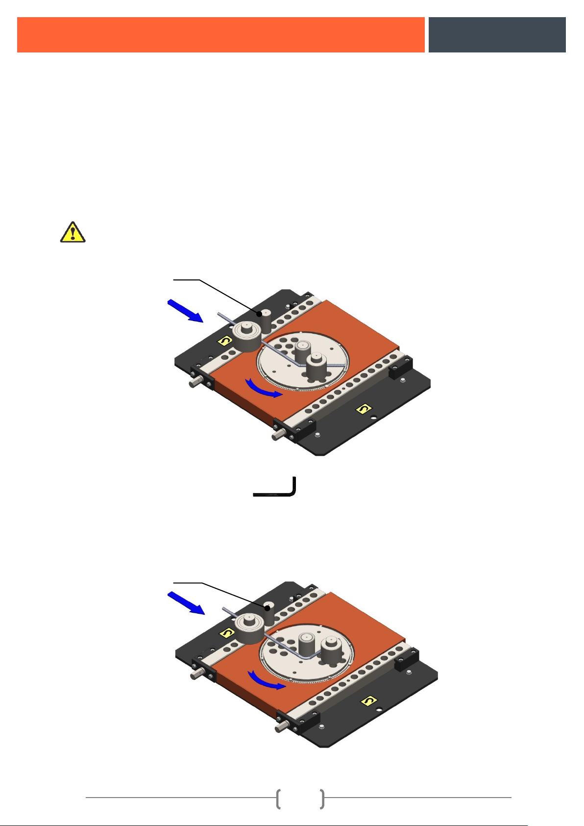
11.3. Protractor Bending Setting (90°):
It is set with the same method carried out in bent bar bending by pressing the P2 button on the
control panel.
NOTE: The required angle is set for P2 BUTTON by moving the figure:10 switch pin 2 to left and
right.
Figure 11: Representation of Protector Bending
Bending pin mounted
with safety purpose
Bending pin mounted
with safety purpose
Page 18
B36
17
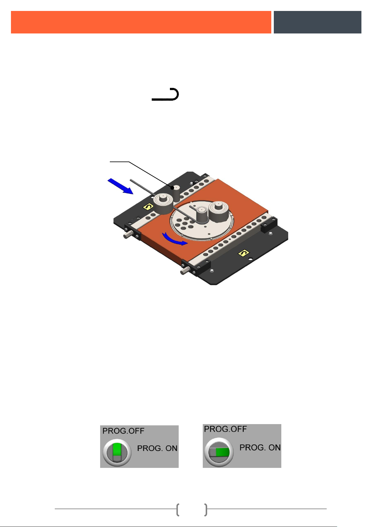
11.4. Hook Bending Settings (180°):
It is set with the same method carried out in bent bar bending by pressing the P3 button on the
control panel.
NOTE: The required angle is set for P3 BUTTON by moving the figure: 10 switch pin 3 to left and
right.
Figure12: Hook Bending demo
11.5. Stirrup Bending:
Stirrup Bending Mode:
Prog. On Stirrup Bending Setting Systems:
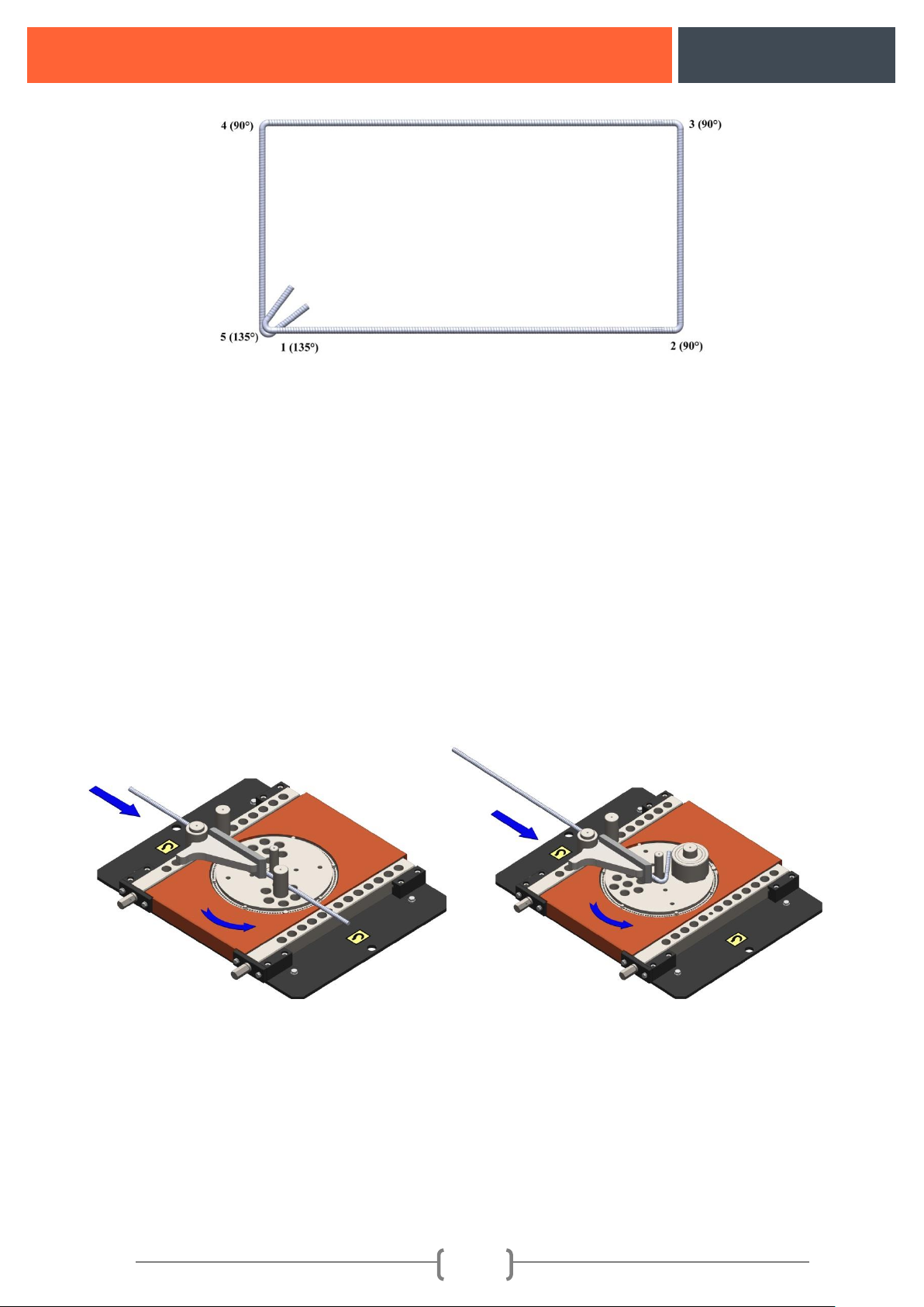
PROGRAM OFF-ON SWITCH BUTTON should be at program ON position. 90° angle which is
used in stirrup bending should be set to P2 button before the program is taken to ON position, the
SWITCH BUTTON should be turned to program non position (clockwise) after the stirrup tip bending
with 135° are set to P3 button. After turning the SWITCH BUTTON, P1 button should be pressed
once. Afterwards P1-P2-P3 buttons will blink only once. This warning indicates that the machine is
ready for programming. After this process, programming starts according to the required bending
angle. For example: Programming for performing stirrup bending shape is described below.
(Figure 9-
(Figure 9-
Bending pin mounted
with safety purpose
Page 19
B36
18
Programming the described shape:
a) Press P3 button for once for the 1st angle,
b) Press P2 button three times successively for 90° bending in 2nd, 3rd and 4th angles.
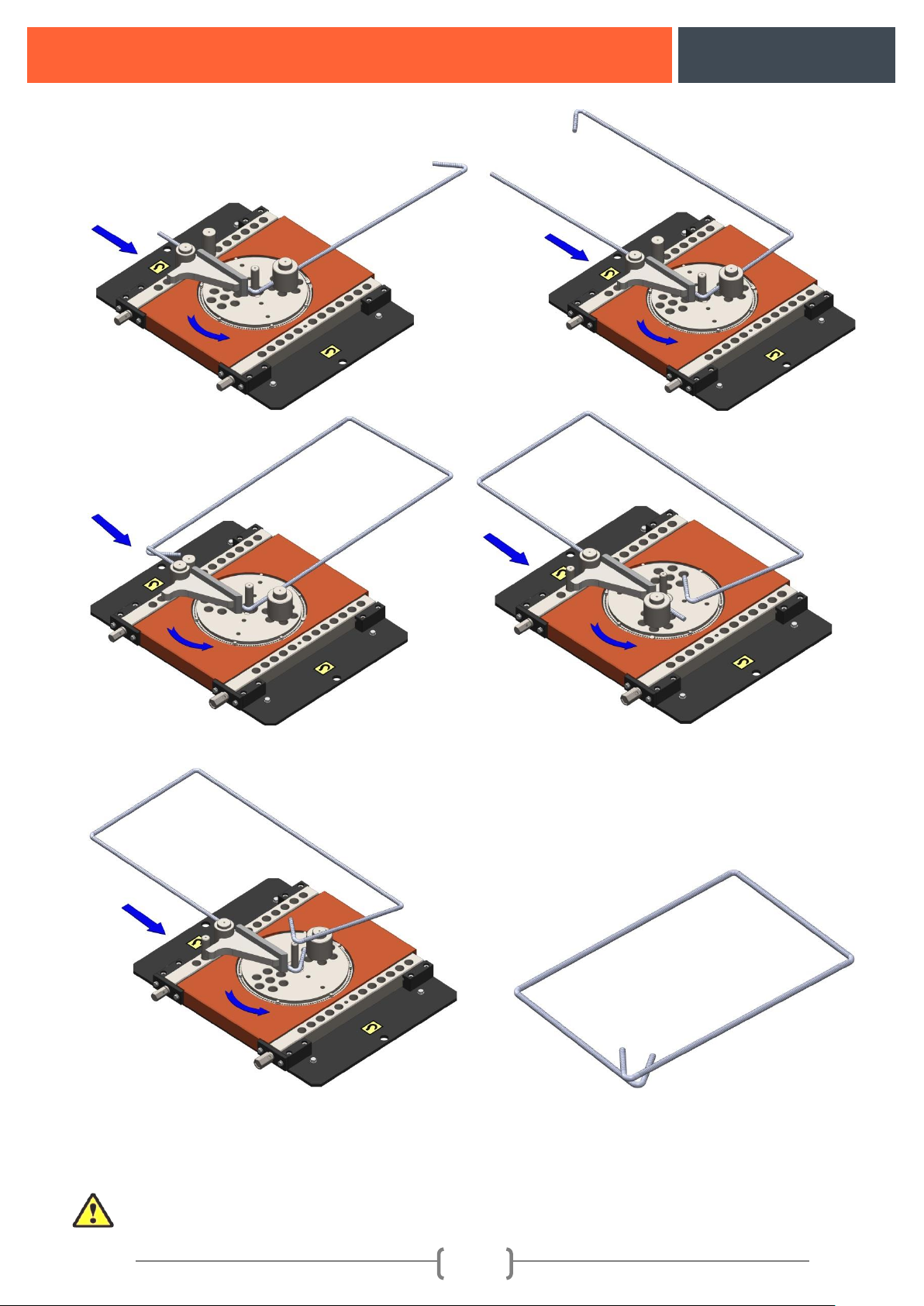
c) The programming process for the 5th angle made after pressing P3 button is saved to the memory by
pressing the foot pedal and programming process is completed. After the setting procedure is
completed (Figures 13a-13b-13c-13d-13e-13f-13h-13h) bending order is followed and Stirrup
Bending should be completed.
NOTE: When the program ON-OFF SWITCH BUTTON is turned to ON position program is
reset and it must be re-programmed. The button should be switched to OFF position as long as it is not
needed. In case it is turned, the program should be redone as it is shown in the example.
NOTE: Iron that will be stirred up should be bent on an appropriate Bending Sleeve, Pin, Stir-up
pin or straight pin with at least 5 times bigger than the bending iron's diameter.
(13a)
(13b)
(13h)
Page 20
B36
19
Figure13: Stirrup bending demo
(13g)
(13h)
(13c)
(13d)
(13e)
(13f)
Page 21
B36
20
WARNING!!!
In order to fix the faults and determine the electricity malfunction if it is required to open the
power panel, power connection of the machine must be turned off and competent technicians should
make the maintenance.
12. MAINTENANCE AND LUBRICATION INSTRUCTIONS
It is important to make maintenance correctly in order to extend service life of the machine and to
ensure safe bending. We suggest for each user to set up a secure system for control and maintenance of
the machine. The following descriptions are given for reference. Number 140 gear oil is used in
machine's reducer unit.
Daily maintenance of the machine
• Clean dust and scales on the machine with a brush.
• If the machine is running outdoors it must be protected from rain water when raining.
• Machine should be checked if there is extraordinary voice or not.
Weekly maintenance of the machine
• Parts driving machine bending plates should be cleaned and lubricated.
• Machine adjusting lever mechanism should be cleaned and lubricated.
Monthly maintenance of the machine:
• Bending pins and bending plates should be checked and any cracked or skewed parts mustn't be
used.
• Reducer should be checked if there is oil leakage or not.
• Machine's sensor display should be checked if it has dirt on it or not and also the lamp behind it
should be checked if it is working or not.
Semi-annual maintenance of the machine:
• All the bolt connections of the machine should be checked.
Annual maintenance of the machine:
• Oil of the machine should be changed.
• If it is out of order seals and bearings should be changed.
• Any skewed, cracked, worn parts should be checked and replaced.
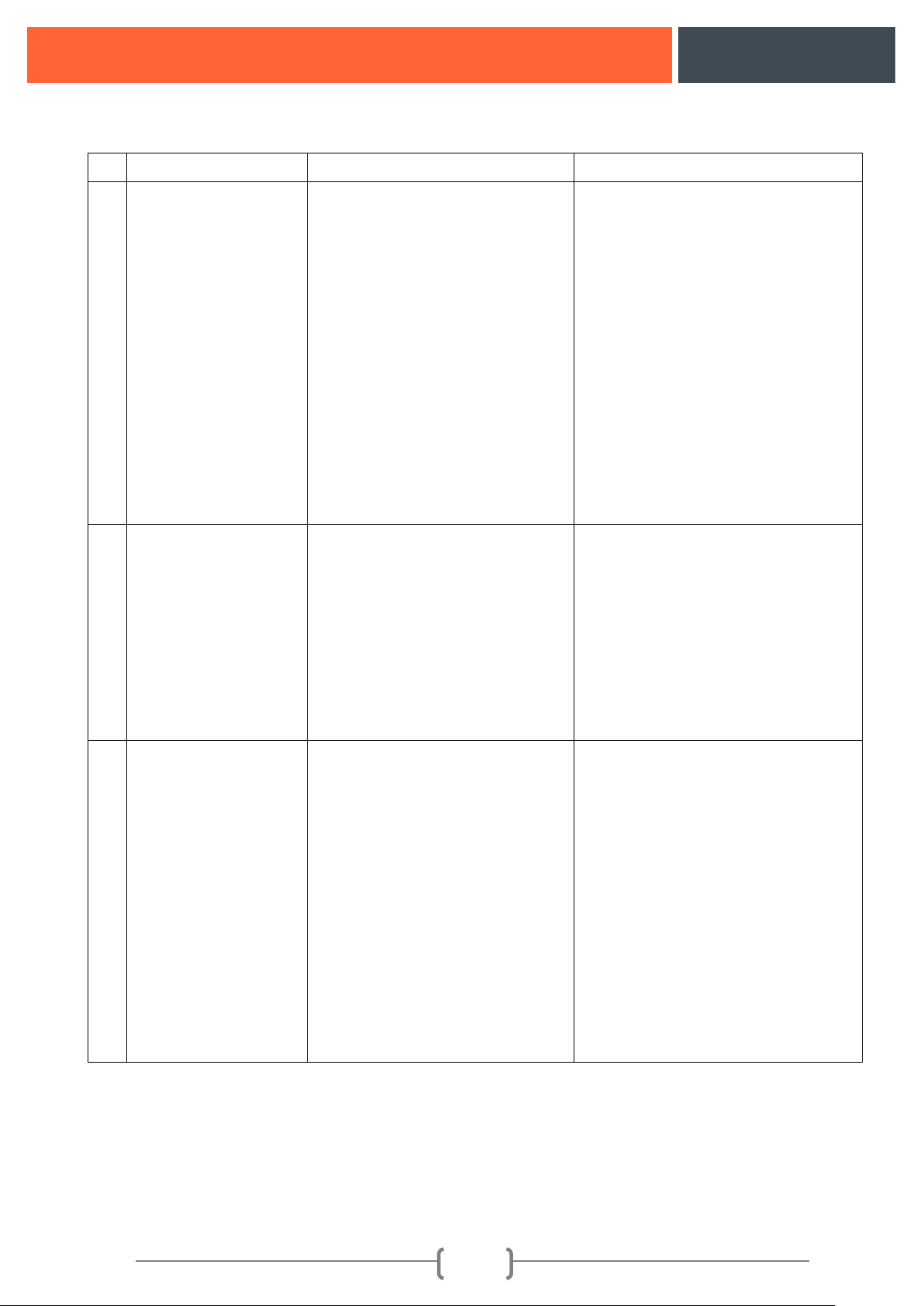
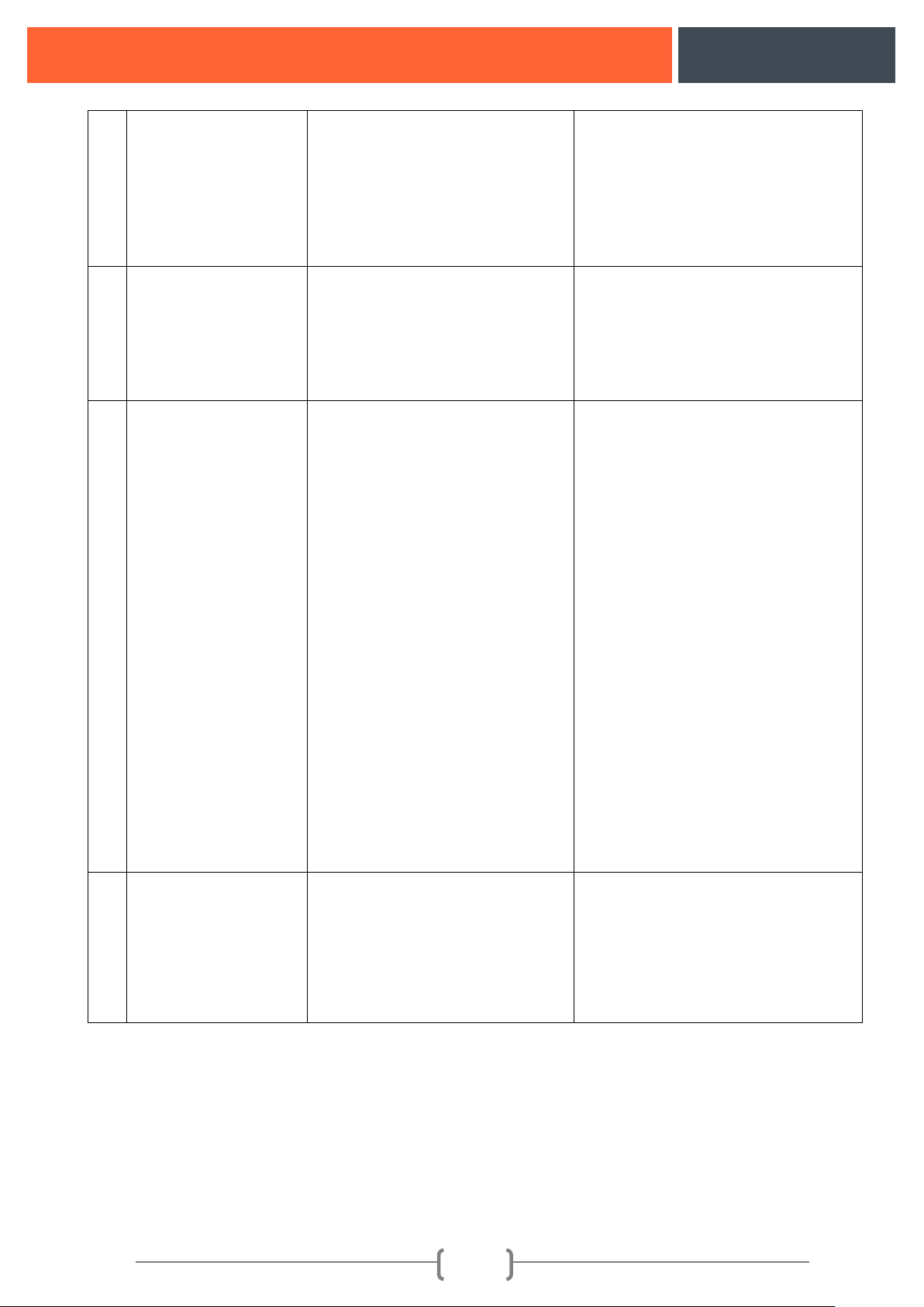
10. FAULTS AND SOLUTION OFFERS
Any faults those might arise when running the machine, and their causes and solutions are given in the
table below.
WARNING!!!
In order to fix the faults and determine the electricity malfunction if it is required to open
the power panel power connection of the machine should be turned off by switching the main
switch to 0 positions and competent technicians should make the maintenance.
Page 22
B36
21
NO
FAULT
DESCRIPTION
SOLUTION
1.
Machine isn't running:
1. Missing phase might come to
the electric supply system where
the machine is connected.
2. Emergency stop button might
be pressed.
3. Motor protection switch might
be blown.
4. LEFT STOP RIGHT switch
might be turned off.
5. Electricity Board Cap might be
open or haven't been closed
completely.
1. Check the phases.
2. Check the button. If it is pressed
open it by turning to the direction of
the arrow on the button.
3. Check the motor protection
switch. If the switch is blown turn it
to the position 1.
4. Check the switch. If it is on stop
position turn it to right or left
positions.
5. Check the Electricity Board Cap.
2.
Bending disk turning
continuously.
1. Sensor might be broken down.
2. There might not be Zero
Adjustment Pin and SWITCH
pins over the machine flange.
3. Direction contactors might be
broken down.
1. Check whether the sensor is
working or not, if it is out of order
replace it.
2. Check the pins and if any of them
is missing, complete it.
3. Check the contactors.
3.
Motor protection
switch is blowing
continuously.
1. Diode might be broken.
2. Motor might be blown.
3. If the machine is bending iron
over its bending capacity:
4. Missing phase might come to
the electric supply system.
5. Transformer might be blown.
6. There might be short circuit or
wearing on the cables.
1. Check the diode.
2. Check the motor.
3. Check the bent iron according to
the material type and measurements
on the capacity plate.
4. Check the phases on the electricity
network.
5. Check the transformer.
6. Check the cable and connections.
Page 23
B36
22
4.
Machine is not
running although the
foot pedal is pressed.
1. The plug might be displaced.
2. Pedal switch might be out of
order.
3. Contactors in the electricity
network might be out of order.
1. Check the plug.
2. Check the SWITCH. Change them
if they are out of order.
3. Check the contactors.
5.
Emergency Stop is not
running.
1. Emergency stop contact might
be out of order.
2. Cable Connections might be
unplugged.
1. Change the emergency stop
button.
2. Check the cable connections.
6.
Machine is making
noise.
1. Bearings might be broken
down.
2. Motor's propeller cap might be
rubbing.
3. Gears might be broken down.
4. There might be no oil in the
reducer.
5. Missing phase might come to
the electric supply system which
the machine is connected.
6. Machine might have difficulty
over its capacity.
7. Brake might not be released or
brake lining might scrape after
being broken down in the
electromagnetic braked machines.
1. Check the bearings.
2. Check the propeller cap.
3. Check the gears.
4. Check the reducer oil.
5. Check the phases in the network.
6. Check the bent iron according to
the capacity plate.
7. Check whether the brakes are
running or not and the brake linings.
7.
Machine is leaking
oil.
1. Reducer ventilation cap might
not be mounted.
2. Motor seal might be leaking
oil.
3. Reducer connection bolts might
be loose.
1. Check whether the plug is
mounted or not.
2. Check the motor from the
propeller side. If there is oil change
the motor seal.
3. Check the connection bolts and if
loose screw.
Page 24
B36
23
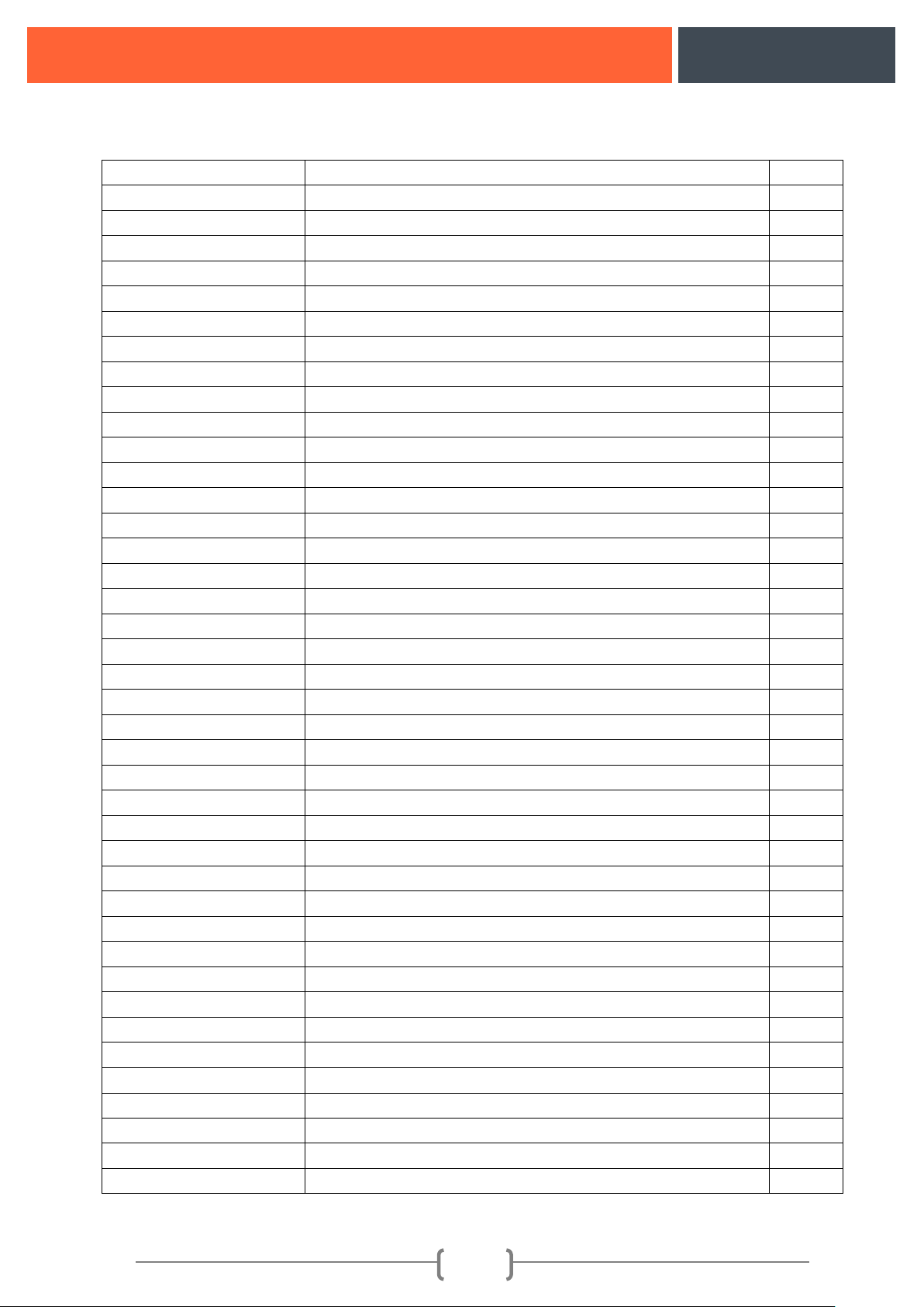
14. MACHINE EQUIPMENT LIST
PART NUMBER
DESCRIPTION
PIECE
B36-01
MACHINE BODY
1
B36-02
PLANET PLATE SHEET
1
B36-03
PLANET REDUCER STEM STEEL
1
B36-04
PLANET REDUCER
1
B36-05
ADJUSTMENT SPANNER
1
B36-06
PLATE
1
B36-07
CE LOGO - PLANET
1
B36-08
COVER HINGE
2
B36-09
ELECTRICAL PANEL
1
B36-10
M12 WASHER
4
B36-11
(M12X35 BOLT DIN933
4
B36-12
Ø70 BENDING SLEEVE
2
B36-13
Ø90 BENDING SLEEVE
1
B36-14
Ø110 LUK BENDING SLEEVE
1
B36-15
(Ø130 BENDING SLEEVE
1
B36-16
SWITCH PIN
6
B36-17
START BUTTON
1
B36-18
STOP BUTTON
1
B36-19
POWER LAMP
1
B36-20
GROUNDING TAG
1
B36-21
SENSOR 2 B36-22
ELECTRICAL PANEL CAP
1
B36-23
P1 BENDING BUTTON
1
B36-24
P2 BENDING BUTTON
1
B36-25
P3 BENDING BUTTON
1
B36-26
REAR CONNECTION PLATES
4
B36-27
LEFT CONNECTION PLATE
2
B36-28
M12 SPRING WASHER
16
B36-29
M12X60 BOLT DIN933
16
B36-30
BENDING PLATE ASSEMBLY
2
B36-31
ADJUSTMENT STUD
2
B36-32
FACE CONNECTION PLATE
2
B36-33
M10 SPRING WASHER DIN 1140
4
B36-34
M10x 30 BOLT DIN933
4
B36-35
ADJUSTER NUT
2
B36-36
M8X10 SETSKUR DIN914
1
B36-37
10X16X44 WEDGE
1
B36-38
BENDING FLANGE
1
B36-39
M6X10 BOLT DIN7985
4
B36-40
ZERO ADJUSTMENT PIN
1
Page 25
B36
24
B36-41
MEDIUM CASING
1
B36-42
RIGHT MAINTENANCE COVER
1
B36-43
PANEL LOCK
2
B36-44
GÖÇMAKSAN WRITING
1
B36-45
LOWER CASE COVER
1
B36-46
M6X15 COUNTERSUNK BOLT DIN6921
8
B36-47
FOOT PEDAL
1
B36-48
EMERGENCY STOP
2
B36-49
HANDLING TAG
2
B36-50
LEFT-RIGHT SWİTCH
1
B36-51
CONTROL PANEL COVER
1
B36-52
BACK MAINTENANCE COVER
1
B36-53
M5X10 BOLT DIN7985
4
B36-54
MAN-AUTO
1
B36-55
CONTROL PANEL
1
B36-56
POWER PLUG
1
B36-57
STIRRUP PIN
1
B36-58
STRAIGHT PIN
1
B36-59
PIN 5 B36-60
RETAINER
1
B36-61
SENSOR NUT
4
B36-62
SENSOR ANGLE
1
B36-63
RIGHT CONNECTION PLATE
2
B36-64
LOCK NUT
2
B36-65
EMERGENCY STOP
2
B36-66
M6X35 COUNTERSUNK BOLT DIN965
8
B36-67
PROG. ON OFF)
1
B36-68
M12X50mm HEXAGON-HEAD BOLT
B36-69
TOOL BOX FOR PLANET
1
Page 26
B36
25
15. MACHINE ASSEMBLY
Page 27
B36
26
16. MACHINE ELECTRICITY SCHEME
Page 28
B36
27
Page 29
B36
28
17. ABOUT COMPANY
GÖÇMAKSAN
 Loading...