

Page 1

GMR maskiner a/s
Saturnvej 17
DK-8700 Horsens
Tel. +45 7564 3611
www.gmr.dk
DK GB DE
SE
FR
Registration for use ............................................................ 2
EC declaration of conformity .............................................. 3
General ............................................................................... 5
Tractor selection ................................................................. 7
Technical information .......................................................... 8
Handling and assembly .................................................... 13
Daily use ........................................................................... 19
Detaching the implement .................................................. 21
Maintenance and storage ................................................. 26
Labelling ........................................................................... 28
Customer services and claims.......................................... 30
User manual
STENSBALLE Rotary mowers
Page 2

Page 3

GMR maskiner a/s
Page 3
STENSBALLE rotary mowers
Operating Instructions
GB
Registration of Use
Stensballe manufactures quality machines for professional users.
The warranty period on our machines is 12 months from the purchase date, and covers any material or
manufacturing defects.
Any parts that have suffered damage as a result of material and production faults will be replaced by
GMR maskiner a/s at no extra charge.
Consequential damage and wearing parts will not be replaced.
A condition for the processing of claims is that this registration for use is submitted to GMR maskiner a/s
no later than 1 month after delivery to the user.
This can be done via our website www.gmr.dk or by completing and scanning/submitting the coupon
below to: GMR maskiner a/s
Saturnvej 17
8700 Horsens, Denmark
stensballe@gmr.dk
Registration for use:
Machine number
Delivery date
Model
End user
Address
Dealer
Page 4

Page 5
GMR maskiner a/s
Page 5
STENSBALLE rotary mowers
Operating Instructions
GB
EC declaration of conformity
EC declaration of conformity
Manufacturer: GMR maskiner a/s
Saturnvej 17, 8700 Horsens, Denmark
Tel.: +45 7564 3611
hereby declares that
machine: Stensballe
machine no.:
date:
is in conformity with the applicable requirements of:
Order of 10 June 2013 implementing Directive 2006/42/EC of the European
Parliament and of the Council as amended, as well as the EMC Directive
2004/108/EC as amended.
Standards applied:
DS/EN ISO 12100:2 011 Safety of machinery - General principles for design
- Risk assessment and risk reduction.
Signature:
Poul Møller Rasmussen
Production Manager
Page 6
GMR maskiner a/s
Page 6
STENSBALLE rotary mowers
Operating Instructions
GB
For safety reasons and to take full advantage of the mower, you should
read the user manual before starting to use the machine. You can nd
detailed technical information about each type of rotary mower and
spare parts on www.gmr.dk.
Contact your dealer if in doubt.
Use only original Stensballe parts in your rotary mower. To order
original parts, contact your dealer or GMR maskiner a/s directly.
This user manual includes an illustrated spare parts list. Read the
introduction to the spare parts list before ordering spare parts.
Your STENSBALLE rotary mower is fully assembled and tested at the
factory, and ready for use.
This user manual applies to all Stensballe rotary mowers. Any
differences in the use and operation of the various types are listed and
described.
Please note the following safety warnings found in this user manual:
Introduction
Mowers described
in this user manual
Safety warnings
CAUTION
Damage to machinery or accessories
A technical procedure or similar which may result
in damage to the machinery or accessories.
WARNING
Risk of personal injury or death
A technical procedure or similar which may be
hazardous and result in personal injury or death.
NOTE
Important information
A very important technical procedure or similar.
General information
Page 7

GMR maskiner a/s
Page 7
STENSBALLE rotary mowers
Operating Instructions
GB
General information
The plastic packaging that the mower is supplied in, is made from
polythene (PE), which can be recycled. The packaging should therefore
be disposed of at your nearest recycling centre.
• unauthorised persons to use the machine unattended.
• a PTO shaft to be used without a CE label.
• the machine to be used without factory installed safety guards.
• people to stand close to the machine while it is in use.
• drivers to leave the tractor cab while the machine is in operation
and the blades are rotating.
• the tractor to stop with the PTO output activated.
• settings to be adjusted while the tractor engine is running.
• the mower to be lifted while it is running.
• the specied speed on the PTO output to be exceeded.
• nuts and bolts are securely tightened and that blades and rotary
parts are inspected for defects.
• the user fully understands how to operate the tractor and the
machine's hydraulic functions and associated movements.
• the working area is checked for wires, steel pipe, large stones,
bottles and other hazardous items and these are removed before
work begins.
• the tractor is stopped and the PTO output is disengaged if
abnormal vibrations or noises are coming from the machine so the
cause can be investigated.
• the tractor's PTO never operates slower than 90% of the machine's
stated PTO rpm.
• the tractor's PTO is disengaged and the tractor is stopped before
performing any adjustments, maintenance or repairs on the
machine.
Packaging
Never allow:
Always ensure that:
Page 8

GMR maskiner a/s
Page 8
STENSBALLE rotary mowers
Operating Instructions
GB
Tractor selection
When choosing a tractor, you should make certain that the rotary
mower and the tractor form a stable unit during operation.
The tractor must be equipped with a front mounting unit with a oating
position function. If the tractor does not have a oating setting, it must
either be equipped with one or the mower must be equipped with a
tting frame with moveable arms.
Rotary mowers types RK/LH, TM/TH and FR/LK may only be tted and
used on tractors that are equipped with operating hydraulics, or tted
with an external hydraulic system. The hydraulic system's operating
lever must be lockable.
Triplex type rotary mowers may only be tted and used on tractors
that are equipped with at least two single or double-acting hydraulic
connections. Both must have a lockable oating position function.
• TM/TH, FR, HP
• BM/FM/FH model P, TM/TH, FR, THM, HC/HCH, R3H
• BM/FM/FH model P, THM/TH
Tractor selection
Tractor/model overview:
Up to 30 HP
From 31-50 HP
51 HP and greater
CAUTION
Locked oating position
If the tractor does not have a locked oating position,
driving on uneven terrain may lift the machine off
the ground and transfer the tractor's weight to the
machine. Both events may damage the wheels or
wheel forks.
Page 9

GMR maskiner a/s
Page 9
STENSBALLE rotary mowers
Operating Instructions
GB
Tractor selection
Noise The driver will be exposed to a noise level in the tractor cabin between
74-85 dB (A). These gures originate from data provided by most
tractor manufacturers in their product specications. The noise varies
between a minimum measured value (machine unloaded) and a
maximum measured value (machine loaded).
The gures require that the machine is tted to a tractor with a cab
that is noise protected with closed windows, and which operates in
an open environment. In addition, the recommended operating speed
is 4-10 km/h. The noise levels also require that the grass length is
10-15 cm and that there is no wind.
If the cab windows, roof window or similar are open, the noise level will
exceed the values stated here.
The rotary mower does not emit any specic type of noise. This means
that the tractor driver will only be exposed to noise from the tractor
itself.
If the driver nds the noise uncomfortable when operating the machine,
GMR maskiner a/s recommends that the driver should wear ear
protection.
Page 10

GMR maskiner a/s
Page 10
STENSBALLE rotary mowers
Operating Instructions
GB
Technical information
Total PTO power The following values represent the total PTO power for the whole
mower. This means that if the mower is operated with both a
mechanical and hydraulic PTO, both the mechanical and the hydraulic
power should be included in the gures.
Cutting
width
Min.
PTO power
Max.
PTO power
Capacity
at 4 km/h
Capacity
at 10 km/h
1150 mm 11 kW 18 kW 0.39 ha 0.97 ha
1300 mm 12 kW 21 kW 0.44 ha 1.1 ha
1500 mm 13 kW 25 kW 0.51 ha 1.3 ha
1800 mm 17 kW 30 kW 0.61 ha 1.5 ha
2100 mm 23 kW 35 kW 0.71 ha 1.8 ha
2500 mm 25 kW 37 kW 0.85 ha 2.1 ha
3000 mm 31 kW 46 kW 1.0 ha 2.6 ha
3500 mm 36 kW 54 kW 1.2 ha 3.0 ha
4000 mm 41 kW 60 kW 1.4 ha 3.4 ha
NOTE
Axle load
The tractor's maximum stated axle load must not
be exceeded. Contact your dealer if in doubt.
CAUTION
Damage to machinery or accessories
If you use tractors which can deliver more than
the stated maximum power, this could overload
and damage the mower.
NOTE
Nominal rpm
The nominal rpm is stated on the mower's xed
PTO shield.
CAUTION
PTO speed
If the PTO speed falls below 90% of the nominal
PTO speed, the mower will be overloaded and
damaged.
Page 11
GMR maskiner a/s
Page 11
STENSBALLE rotary mowers
Operating Instructions
GB
Handling and assembly
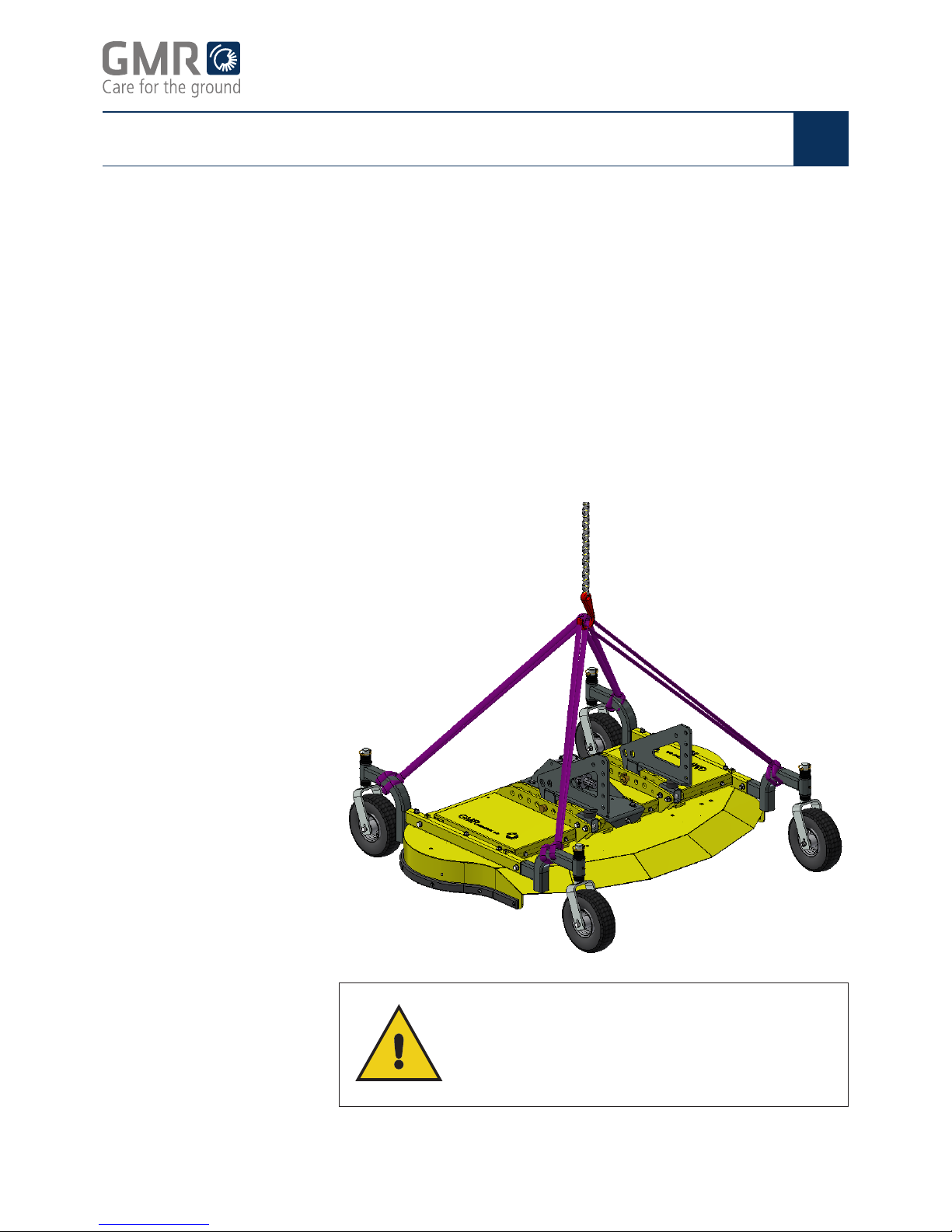
Lifting and moving
the mower
Type: HC/HCH and HP
as well as BRK, BR, RK,
TM/TH, FR, R3H, 2W and
Triplex
Always use a crane to move or lift the rotary mower to carry out
maintenance.
Use four straps or similar with eyes. Place a strap around each wheel
arm, and assemble the four straps in a focal point in the centre above
the mower. Lift the mower from this point.
Remove the PTO shaft before lifting. Please be aware that when the
mower is lifted, it may move unexpectedly. The mower should not be
lifted quickly or unintentionally, to avoid the risk of personal injury.
When lifting the Triplex mower, the side mowers may be in both the
operating and transport positions.
WARNING
Safety zone
When lifting the mower, all persons must stay clear
of the machine.
The safety zone is min. 2 metres.
Page 12

GMR maskiner a/s
Page 12
STENSBALLE rotary mowers
Operating Instructions
GB
Handling and assembly
Attaching the mower
to the tractor
3-point hitch
When tting for the rst time, remove the reusable plastic packaging.
• Check that the correct type of machine has been delivered.
• Check that the machine is complete and has not suffered damage
in transit.
• Check that the rpm and direction indicated on the PTO protection
on the angular gear are correct for the tractor (not applicable for
hydraulic machines).
Depending on the type of mower you are using, attach the mower with
either a 3-point hitch or an A-frame.
1. Drive the tractor at right angles to the mower.
2. Stop the tractor engine and PTO output.
3. Connect the hitch arms to the mower.
4. Connect the top bar to the mower.
5. Connect the PTO shaft to the tractor.
Check that the snap coupling clicks into place in both forks.
6. Attach the PTO shaft safety chains to the sides of the tractor
(mechanical machines only).
7. Connect the hydraulic hoses to the tractor using the snap couplings
(hydraulic machines only).
8. Check that the couplings are tted so the mower rotates in the
correct direction.
9. Check the snap couplings for impurities.
Clean the couplings if necessary.
Page 13

GMR maskiner a/s
Page 13
STENSBALLE rotary mowers
Operating Instructions
GB
Handling and assembly
Drive the tractor at right angles to the mower.
1. Lower the male section of the tractor and drive it under the female
section.
2. Lower the male section so it locks into the female section. Activate
the manual locking system, or check that the automatic locking
system is activated.
3. Lift the machine slightly.
4. Stop the tractor engine.
5. Connect the PTO shaft to the tractor.
6. Check that the snap coupling clicks into place in both forks.
7. Attach the PTO shaft safety chains to the sides of the tractor
(mechanical machines only).
8. Connect the hydraulic hoses to the tractor using the snap couplings
(hydraulic machines only).
9. Check that the couplings are tted so the mower rotates in the
correct direction.
10. Check the snap couplings for impurities.
Clean the couplings if necessary.
WARNING
Safety zone
Never manoeuvre the tractor hitch if there are people
in the vicinity.
The safety zone is min. 2 metres.
Example illustration. Design and positioning will vary depending on implement and tractor.
A-frame
Page 14

GMR maskiner a/s
Page 14
STENSBALLE rotary mowers
Operating Instructions
GB
Handling and assembly
Connecting the hydraulic
hoses
Mount the mower on the tractor by coupling the hydraulic hoses to the
tractor's double-acting output.
Remember to keep the hydraulic hoses correctly separated in pairs so
that the two hoses from one cylinder go to one double-acting hydraulic
output.
The outputs for A and B functions should have a oating position.
The illustration below shows the function chart for Triplex mowers.
CAUTION
Mechanical operation
Attaching the mower for the rst time:
Before coupling the PTO shaft to the tractor, position
the mower where the distance between the PTO
output and the mower's PTO input is shortest. This
ensures that the PTO shaft is not too long and is not
damaged when lifting the mower.
Follow the instructions in the user manual when
shortening the PTO shaft. Contact your dealer if you
have any questions about the above.
Page 15

GMR maskiner a/s
Page 15
STENSBALLE rotary mowers
Operating Instructions
GB
Handling and assembly
CAUTION
Hydraulic hoses
Connect the hydraulic hoses so that they
cannot come into contact with moving parts.
NOTE
Shortening the hoses
The hydraulic hoses are supplied in standard lengths.
If the hoses need to be shortened, this should be
done by the dealer.
CAUTION
Make sure that the machine's standard PTO speed
and direction of rotation can be met by the tractor.
Page 16

GMR maskiner a/s
Page 16
STENSBALLE rotary mowers
Operating Instructions
GB
Daily use
There are various ways to set the cutting height depending on the type
of mower used.
Use four straps or similar with eyes. Place a strap around each wheel
arm, and assemble the four straps in a focal point in the centre above
the mower. Lift the mower from this point.
Adjust the cutting height using the two spindle handles on the top of the
wheel boxes.
A height adjustment scale is attached to the side of the wheel box.
This is only a guide.
1. Determine the cutting height.
2. Measure the current cutting height from the ground to the lower
edge of the rotor guard in centimetres.
3. Start the tractor, lift the mower, and then stop the tractor again.
4. Adjust the wheels in relation to the measured cutting height. On
Triplex mowers, it may be necessary to set the centre mower one
ring higher than the side mowers to take account of the mower's
weight distribution and the ground's carrying capacity.
Example
Measured cutting height ........... 5 cm
Required cutting height ............ 4 cm
Remove the split pin and move the wheel up one ring (one ring = 1 cm),
then reattach the wheel and repeat for all eight wheels.
The mower may have one or two rollers which help to protect the
blades. The rollers have three adjustment options:
• Regular hilly terrain = top setting
• Average hilly terrain = middle setting
• Very hilly terrain = bottom setting
Height adjustment
Height adjustment
with lever
Type: FM, BM, FH
Height adjustment
on each wheel
Type: Triplex, BRK, RK,
TH/TM, 2W, HC/HCH, HP
Rollers
Page 17

GMR maskiner a/s
Page 17
STENSBALLE rotary mowers
Operating Instructions
GB
Daily use
The following applies to mowers where the cutting height is adjusted by
means of hydraulics controlled from the tractor cab.
1. Lower the mower to the lowest position and activate the hydraulics
for 10-20 seconds until all the adjustment cylinders are completely
in the outer position, and no air is left in the system. Use this
method to reset the cutting height, so all the cutting units are at
exactly the same height.
2. Raise the mower to the desired cutting height. Use the guide scale
on the inner, left cylinder.
If there is a difference in height, you can reset the system by lowering
the cutting height all the way to the bottom position, and activate the
hydraulics until all the cutting units are at the bottom, and no air is left in
the system. You can now set the height as described above.
Before you start the machine, you should inspect the working area and
remove any foreign objects.
If the machine is hydraulically driven, you must ensure that you are
well-acquainted with the machine's hydraulic functions.
STENSBALLE mowers are only designed to mow grass and no other
forms of vegetation. Avoid mowing areas with more robust vegetation.
Pay attention to any foreign objects and avoid them as much as
possible. Mowing in areas with more robust vegetation will lead to
greater wear on the blades and may lead to undue damage to the
machine and mean that your warranty will be voided.
Mowing in high and/or thick grass restricts the forward driving speed.
We recommend a speed range of 4-10 km/h. As the owner of this
mower, you should be careful to maintain the nominal rpm, despite
the load on the mower.
The machine must run on its own wheels while mowing. It must not
hang in the tractor's hitch.
Central, hydraulic
height adjustment
Type: BR/LM, FR/LM, FR/
LH, R3H, Triplex C
CAUTION
Foreign objects can cause major damage to the rotor
blades and other parts in the transmission.
If the rotor blades collect foreign objects, stop and
clean the mower immediately.
Page 18

GMR maskiner a/s
Page 18
STENSBALLE rotary mowers
Operating Instructions
GB
Daily use
Start-up procedure
for mechanically
driven machines
1. Check that the tractor's PTO output is disengaged.
2. Start the tractor and leave it idling at high speed.
3. Engage the tractor's PTO output and let the machine idle while
checking the machine's moving parts rotate freely and unhindered.
4. For Triplex mowers: Raise the side mowers to vertical, and make
sure that the engine is disengaged and the blades have stopped.
Lower the mowers again and set the valve to the oating position.
5. Increase the PTO rpm to the standard rpm and allow the machine
to run for 60 seconds. Check for abnormal vibrations or noises
coming from the machine.
If there are abnormal vibrations or noises, contact your dealer
immediately.
6. Reduce the tractor engine's rpm to idle and disengage the PTO
output to stop the mower.
1. Check that the tractor's hydraulic connection is in the neutral
position.
2. Start the tractor and leave it idling at high speed.
3. Engage the tractor's operating hydraulics and let the machine
idle while checking the machine's moving parts rotate freely and
unhindered.
On Triplex type mowers, raise the side mowers to vertical. Make
sure that the hydraulic engines are disengaged and the blades
have stopped. Lower the mowers again and set the valve to the
oating position.
4. Increase the tractor engine's rpm to the standard rpm and allow
the machine to run for 60 seconds. Check for abnormal vibrations
or noises coming from the machine. If there are abnormal
vibrations or noises, contact your dealer immediately.
5. Reduce the tractor engine's rpm to idle and set the hydraulic
control handle to the neutral position.
Start-up procedure
for hydraulically
driven machines
WARNING
Safety zone
During start-up and use, the mower must be lowered
to the ground, before engaging the mechanical or
hydraulic PTO output.
Disengage the PTO output before lifting. Failure to do
so means there is a risk of personal injury on contact
with rotating parts (blades).
Page 19

GMR maskiner a/s
Page 19
STENSBALLE rotary mowers
Operating Instructions
GB
Daily use
Transport
Side ejection
Special instructions
for Triplex mowers
Stop the tractor PTO output during transport between mowing areas
and raise the hitch into the top position. Check regularly that the hitch
is in the top position.
We recommend that mowers with side ejection are driven so the grass
is ejected to the side where the grass is mown.
Triplex mowers can benet from several different driving positions
for use in different situations.
There may be situations with trees in the middle of the eld, so it can
be an advantage to lift one of the side mowers.
Page 20

GMR maskiner a/s
Page 20
STENSBALLE rotary mowers
Operating Instructions
GB
Daily use
The mower is designed with a xed guard which follows the cutting
height. This means that when the mower is set at the high cutting
height, the guard will be the same distance from the ground.
When driving with the mower, the hitch must be in the oating position,
so the side mower can follow the terrain.
If the hitch is not in the oating position, the weight may transfer from
the tractor to the mower, which could overload both the centre mower
and the side mowers.
When driving with the Triplex mower, the hydraulic outputs must be in
the oating position, so the side mower can follow the terrain.
If the hydraulic outputs are not in the oating position, the weight may
transfer from the tractor to the mower, which could overload both the
centre mower and the side mowers.
WARNING
The tractor driver must stop the machine immediately
if anyone moves into the danger zone.
WARNING
Never lift the side mowers while anyone is within
the danger zone.
WARNING
Safety zone
When operating the mower, all persons must stay
clear of the machine.
The safety zone is min. 2 metres.
Danger zone
Floating position
Special instructions
for Triplex
Page 21

GMR maskiner a/s
Page 21
STENSBALLE rotary mowers
Operating Instructions
GB
Daily use
In case of a breakdown, proceed as follows:
1. Reduce the tractor's rpm to idle.
2. Disengage the tractor's PTO output or operating hydraulics.
3. Stop the engine before leaving the cab.
Contact your dealer if you cannot identify the cause of the breakdown.
If the mower fails during use, you must stop the tractor's mechanical
or hydraulic PTO output immediately. Then stop the tractor engine
before leaving the driver's cab. You can now inspect the mower to
nd the cause.
If the centre mower has stopped, the V-belts may be slipping due to
overloading or the V-belts may need tightening.
If the mower is forced too much, the tractor's hydraulic pressure relief
valves are activated and one or both side mowers stops mowing.
If the mowing action is failing and you need to restart, proceed as
follows:
Stop the tractor's PTO immediately if the rotary mower is not running,
and contact your dealer for assistance.
WARNING
Contact your dealer if you cannot identify the cause
of the mowing failure. You risk personal injury if you
troubleshoot without thorough knowledge of the
machine and technology in general.
Breakdown
Failure
Mechanical operation
Hydraulic operation
Restart
1. Stop the tractor's PTO and run back a little.
Then attempt a restart as follows:
2. Check that the PTO output is disengaged.
3. Start the tractor and drive the mower free of the grass.
4. Engage the PTO output.
5. If the rotary mower is now running, you can continue to mow the
grass, but drive a little more slowly than before.
Page 22

GMR maskiner a/s
Page 22
STENSBALLE rotary mowers
Operating Instructions
GB
Detaching the implement
Hydraulic oil
Danger signs
In case of heat:
In case of vibration
and noise:
When operating the mower, you should ensure that the temperature
does not exceed 80 °C. After prolonged heavy use of the mower, the oil
may get very hot.
If there are signs of heat generation, vibration or noise during operation,
you must stop the mower and then the tractor immediately.
Inspect the mower.
• Check for dry grass under the shielding/guards by the V-belts.
• Check if the gears and/or bearings are overloaded.
• Check all transmission parts.
• Check the blades carefully for damage (breakages).
Page 23

GMR maskiner a/s
Page 23
STENSBALLE rotary mowers
Operating Instructions
GB
Detaching the implement
Detaching the mower
All types
3-point hitch
A-frame
F model tractors
The method for detaching the mower varies depending on whether a
3-point hitch or an A-frame is used.
The mower must be detached on a level surface.
1. Carefully lower the mower down onto the surface and stop the
tractor engine.
2. Remove the PTO shaft from the tractor and attach the free end to
the mowers using the safety chain.
3. On hydraulically driven models: Remove the quick release
connections from the tractor and attach the dust caps. Next, lay
the hoses across the mower.
After completing steps 1-3 above, proceed as follows:
4. Remove the pin for the top bar on the mower, so that the top bar is
only attached to the tractor.
5. Remove the pins for the hitch arms.
6. Drive the tractor free of the mower.
After completing steps 1-3 above, proceed as follows:
4. Disable the locking system, so the male and female parts are
released from each other.
5. Start the tractor engine and lower the male part.
6. Drive the tractor free of the mower.
1. Disengage the top bar from the mower.
2. Remove the rear assembly pins.
3. Lower the mower to the ground and remove the front assembly
pins.
4. Drive the tractor free of the mower.
5. Insert the assembly pins and safety pins in the mower.
Page 24

GMR maskiner a/s
Page 24
STENSBALLE rotary mowers
Operating Instructions
GB
Maintenance and storage
Manual tilt-up
Hydraulic tilt-up
Use manual tilt-up when you need to clean the mower.
1. Lower the mower to the ground.
2. Disengage the PTO output.
3. Stop the tractor.
4. Remove the PTO shaft and place it to one side. Applies to
mechanical machines only.
5. Start the tractor and lift the hitch with the mower in the top position.
6. Tip the mower by hand into an almost vertical position.
7. Lock the mower in tilt-up position using pins through the mounting
bracket and frame. Depending on the type of tractor, it may be
necessary to turn the rear wheels so they are pointing forward.
8. Gently lower the mower to the ground, so the rear wheels are
resting on the surface.
9. Stop the tractor and remove the key before you leave the tractor
cab.
Some mowers may be equipped with hydraulic tilt-up.
1. Disengage the hydraulic PTO output.
2. Stop the tractor.
3. Remove the PTO shaft and place it to one side.
Applies to mechanical machines only.
4. Turn the lever on the switch valve to the tilt-up position.
5. Start the tractor.
6. Lift the hitch with the mower in the top position.
7. Activate the valve battery for tilt-up, and make sure the mower
moves freely and unhindered to the top position. Depending on the
type of tractor, it may be necessary to turn the rear wheels so they
are pointing forward, or to detach them completely with the wheel
forks.
8. When the mower is tipped right up, you can gently lower the mower
with the hitch so it rests on the ground.
9. Stop the tractor and remove the key before you leave the
tractor cab.
WARNING
Working under a raised mower
Never enter the space under a raised mower unless
it has sufcient support.
Page 25

GMR maskiner a/s
Page 25
STENSBALLE rotary mowers
Operating Instructions
GB
Maintenance and storage
After cleaning
Lubrication
Daily
After 50 operating hours
Angular gear
1. Start the tractor and raise the hitch into the top position.
2. Tilt the mower down to horizontal, and continue to activate the
hydraulic valve until the cylinder is completely in the outer position.
3. Lower the mower to the ground.
4. Stop the tractor and remove the key before you leave the tractor
cab.
5. Turn the lever on the switch valve back to the working position.
6. Attach the PTO shaft. (Applies only to mechanical machines)
The machine has labels attached for grease and oil lubrication,
respectively.
• Wheel bushings grease
• Wheel hub grease
• Bearing housing
for rotary shafts grease
• Cylinder eyes grease
• Adjustable tilting arm oil
• Fixed tilting arm grease
The angular gear is half lled with oil at the factory. According to the
gear manufacturer, the rst oil change should be performed after 50
working hours and subsequently at intervals of 500-800 hours, but at
least once per year.
To prevent sedimentation, we recommend that you change the oil while
it is warm. Use an SAE 90 EP oil. If necessary, use an oil syphon to
remove the used oil.
Page 26

GMR maskiner a/s
Page 26
STENSBALLE rotary mowers
Operating Instructions
GB
Maintenance and storage
The rotary mower is tted with 2 or 4 V-belts which are tightened with
the gear/engine bracket.
After the rst 5 hours of use, check that the V-belts are tight enough.
Tighten them if necessary. Then check after every 40 hours of
operation that the V-belts are tight enough and tighten them if
necessary.
New V-belts will stretch a lot during the rst few hours of use.
You must therefore retighten the V-belts after 5 hours of use.
1. Make sure that the tractor engine has stopped and the PTO output
is disengaged.
2. Remove the outer shielding/guards.
3. Unscrew the bolts in the gear bracket and tighten the belts by
adjusting the clamping bolt on the gear bracket, so that the free
section of the belts can be deformed by approx. 3 cm in either
direction by hand.
4. Then retighten the gear bracket.
5. Bolt the shields rmly back in place.
V-belts
Tightening and retightening
V-belts
Replacing V-belts
Rotary shafts
1. Make sure that the tractor engine has stopped and the PTO output
is disengaged.
2. Unscrew the bolts in the gear bracket.
3. Slacken the belts by loosening the locking nut on the adjustment
bolt on the front of the gear bracket and remove the locking nut.
4. Detach the gear bracket unit and remove the V-belts.
5. Place the new belts loosely around the front centre pulley and t
the gear bracket unit back in place.
Make sure that all the belts are behind the angular gear pulley, and
the clamping bolt passes through the hole in the front of the gear
bracket plate.
6. Insert the 4 set screws in the gear bracket and put the nuts on
without tightening them.
7. Attach the V-belts on the outer pulleys. Check that the belts are
sitting in the right guides.
8. Tighten the V-belts.
9. Tighten the gear bracket.
After the rst ve hours of operation:
• Check and retighten the pulleys.
• Check that the blades and any slide plates are tightened.
Page 27

GMR maskiner a/s
Page 27
STENSBALLE rotary mowers
Operating Instructions
GB
Maintenance and storage
Replacing the bearing unit
Special instructions
for HC/HCH
Blades
Follow the method described for replacing V-belts, but do the following
after removing the belts:
Remove the bearing unit without detaching the pulley by loosening
the 4 bolts that x the bearing unit to the rotor guard, and pulling the
bearing unit out of the bottom of the mower.
On HC/HCH mowers, the V-belt pulley must be detached before the
bearing unit can be removed.
The blades are made of boron-alloyed steel, drop-forged and hardened,
so they can cope with the loads and shocks that are expected to occur
during operation. The hardness of the blades is controlled constantly
and all blades are stamped with GMR followed by the spare part
number.
WARNING
Using blades made by other manufacturers risks fatal
injury.
The machine warranty will be void if they are used.
WARNING
Before sharpening the blades on Triplex side mowers,
the side mower must rst be secured as shown in the
illustration below. Failure to do so means there is a
risk of personal injury.
Page 28

GMR maskiner a/s
Page 28
STENSBALLE rotary mowers
Operating Instructions
GB
Maintenance and storage
Sharpening the blades The blades can be sharpened while they are mounted on the mower,
or they can be detached and sharpened. Always make sure that the
blades are sharpened evenly and are balanced. After sharpening,
hang the blade on a nail or similar to check the result.
The blade must always be sharpened on the inclined upper side.
1. Start the tractor engine.
2. Raise the mower to the top lifting position.
3. If the mower is equipped with the hydraulic tilt-up function, tilt the
mower into an almost vertical position.
4. Stop the tractor engine.
5. If the mower is not equipped with the hydraulic tilt-up function,
lift the front edge of the mower by hand into an almost vertical
position.
6. Secure the mower position with the supplied locking bolt through
one of the slots in the mounting brackets and the mounting bracket
plate on the centre mower.
7. It may be necessary to detach the rear support wheels and wheel
forks before tilting the mower vertically.
The blades can now be serviced. After sharpening, hang the blade on
a nail or similar to check the result.
WARNING
Never allow the blades to rotate when cleaning the
mower.
NOTE
To ensure a correct and ne cut, the blade material
must be sharpened to max. 5 mm. At this point,
the blades should be replaced.
See the illustration below.
Page 29

GMR maskiner a/s
Page 29
STENSBALLE rotary mowers
Operating Instructions
GB
Maintenance and storage
All moving parts on the mower are shielded to prevent accidents
related to the use of the machine.
All safety guards must be intact. In the event of damage or wear to the
guards, they must be replaced or repaired by the dealer. Safety guards
must only be removed using the proper tools.
Replace the hydraulic hoses when there are:
• leaks in the hose and rubber material.
• severe cracks in the rubber material.
Order new hoses from the spare parts list at the back of this manual.
• Clean the mower and loosen the V-belts at the end of the season.
• Clean the blades carefully and lubricate them with oil. This prevents
corrosion and extends the life of the blades.
• Check the oil level in the tank and top up if necessary.
• Store the mower in an area with low air humidity, protected from
rain and snow.
WARNING
Using the machine without safety guards risks fatal
injury.
Safety guards
Replacing
the hydraulic hoses
Storage
Page 30

GMR maskiner a/s
Page 30
STENSBALLE rotary mowers
Operating Instructions
GB
Labelling
Warning labels
The machine bears the following plates/labels. They must be attached
to the machine and be clearly visible. New plates/labels can be ordered
from the dealer.
Warning against contact with blades:
Warning of crushing hazard:
Do not pressure clean:
Page 31

GMR maskiner a/s
Care for the ground
www.gmr.dk
Type:
kW:
No.:
Kg.
Page 31
STENSBALLE rotary mowers
Operating Instructions
GB
Labelling
The machine is equipped with a type plate with an engraved machine
number. The rst two digits of the serial number indicate the year of
manufacture. The machine number is unique to the particular machine,
and GMR maskiner a/s will always be able to refer back to that machine
if the number is quoted.
This plate also states the weight of the machine in kg and its power
requirement in kW.
The label indicates that the machine complies with the EC Machinery
Directive, the year of manufacture and the manufacturer's website.
It is the dealer's responsibility to deliver the machine (and assemble if
required), to start it on delivery or rst use, and to instruct the operator
about the use and maintenance of the machine (including tightening
bolts and nuts).
The dealer is also obliged to make sure that the service manual and
spare parts list is delivered to the customer and that the registration for
use is completed correctly and sent to GMR maskiner a/s no later than
1 month from the date of sale. (See page 3)
Type plate
CE labelling
After-sales service
Page 32

GMR maskiner a/s
Page 32
STENSBALLE rotary mowers
Operating Instructions
GB
Customer services and claims
Claims The warranty period on GMR machines is 12 months from the purchase
date, and covers any material or manufacturing defects. These parts
will be replaced by GMR maskiner a/s free of charge. Consequential
damage and wear and tear will not be replaced.
Any components which are not manufactured by GMR maskiner a/s are
included under the terms of the warranty to the extent authorised by the
supplier of the parts in question.
GMR maskiner a/s reserves the right to assign a claim of this kind
to the relevant supplier and not to reach a decision until the relevant
supplier has responded.
The following must be observed when working on a claim:
• report the claim to GMR maskiner before the repair is started
• agree a time period with GMR maskiner for qualied technicians to
carry out the repair
• any labour costs will only be approved at a xed net price.
If GMR maskiner a/s has not authorised repair work in advance, any
invoice submitted for repair work will not be approved.
At GMR maskiner a/s' request, before the claim can nally be handled,
any parts that were replaced must be sent carriage paid to the factory.
GMR maskiner a/s retains the exclusive right to determine the extent to
which a part shall be replaced or repaired.
The warranty does not cover:
• normal wear and tear or damage which has resulted from
inadequate maintenance.
• damage caused by collision.
• non-compliance with the product's technical specications or if the
product is used for a purpose other than that described in the user
manual.
If the product is altered or if non-original spare parts are used, all rights
under the warranty will be rendered void.
The purchaser does not have the right to require that design changes
on future models are implemented in a pre-existing machine.
Page 33

GMR maskiner a/s
Page 33
STENSBALLE rotary mowers
Operating Instructions
GB
Customer services and claims
In the event
of a complaint:
Complaints must be registered directly with GMR maskiner a/s.
Complete a complaint report, stating the machine type, production
number and date of its delivery to the customer, and send it to us. This
is done via the dealer login on our website www.gmr.dk.
If questions arise about claims on imported machines, we reserve
the right to present the claim to the manufacturer before making any
decision about whether the claim can be accepted.
Our machinery is subject to the EC Machinery Directive and quality
assured within the European Union. We make every effort to comply
with these requirements and do our utmost to supply high quality
machinery.
Horsens, 01.06.2017
GMR maskiner a/s
Page 34

Copyright, GMR maskiner a/s ©
Saturnvej 17
DK-8700 Horsens
www.gmr.dk
25012018
 Loading...