

GMR STAMA Micro, STAMA Parker, STAMA Multi, STAMA Evo, STAMA Mini Operating Instructions Manual
...Page 1

GMR maskiner a/s
Saturnvej 17
DK-8700 Horsens
Tel. +45 7564 3611
www.gmr.dk
DK GB DE
SE
FR
Registration of Use ............................................................. 3
EU declaration of conformity .............................................. 5
General information ............................................................ 6
Safety requirements ........................................................... 7
Operating ............................................................................ 9
Maintenance ..................................................................... 10
Lead-acid batteries ............................................................11
Lithium-ion batteries ......................................................... 18
Marking/labelling............................................................... 23
Customer services and claims.......................................... 24
Operating Instructions
STAMA Micro, Parker, Mini, Multi,
Evo, Maxi EL
Page 2

Page 3
GMR maskiner a/s
STAMA Micro, Parker, Mini, Multi, Evo, Maxi EL
Registration of Use
Page 3
Operating Instructions
GB
Registration for use:
Machine number
Delivery date
Model
End user
Address
Dealer
STAMA manufactures quality machines for professional users.
The warranty period on our machines is 12 months from the purchase date, and covers any material
or manufacturing defects.
Any parts that have suffered damage as a result of material and production faults will be replaced
by GMR maskiner a/s at no charge.
Compensation will not be given for consequential damage or wearing parts.
A condition for the processing of claims is that this registration for use is submitted to GMR maskiner a/s
no later than 1 month after delivery to the user.
This can be done on our website at www.gmr.dk
or by lling in and forwarding or scanning the form below to: GMR maskiner a/s
Saturnvej 17
DK-8700 Horsens
stensballe@gmr.dk
Page 4

Page 5
GMR maskiner a/s
STAMA Micro, Parker, Mini, Multi, Evo, Maxi EL
EU declaration of conformity
Page 5
Operating Instructions
GB
EU declaration of conformity
Manufacturer: GMR maskiner a/s
Saturnvej 17, 8700 Horsens, Denmark
Tel.: +45 7564 3611
hereby declares that
machine: STAMA
machine no.:
date:
is in conformity with the applicable requirements of:
Directive 2006/42/EC of the European Parliament and of the
European Council of 17 June 2006 on the approximation of
the laws of the Member States relating to machinery.
Signature:
Page 6

GMR maskiner a/s
STAMA Micro, Parker, Mini, Multi, Evo, Maxi EL
General information
Page 6
Operating Instructions
GB
Please read the Operating Instructions before you start to use your new
STAMA truck.
If you are in any doubt, contact the dealer.
Use only original STAMA parts in your electric truck. To order original
parts, contact your dealer or GMR maskiner a/s directly.
The truck is fully assembled and tested at the factory. It is ready for
use.
The STAMA truck is a product, the design of which is based on
the practical experiences of users, e.g. graveyards and housing
associations.
General comments
Page 7

GMR maskiner a/s
STAMA Micro, Parker, Mini, Multi, Evo, Maxi EL
Safety requirements
Page 7
Operating Instructions
GB
The truck starts smoothly and continues to accelerate until it reaches
maximum speed.
Acceleration
Intended use
Normal use
The truck is intended to carry stone, gravel, soil, branches and waste.
Max last, Micro = 350 kg
Max last Parker = 500 kg
Max last, Mini = 750 kg
Max last, Multi, Evo and Maxi = 1000 kg
The operator must sit on the seat when driving. The truck stops if
contact with the seat is interrupted for more than 1 second.
Light The operator must ensure that there is sufcient light when driving the
truck so that potential obstacles are clearly visible.
Maximum speed Micro 12 km/h
Parker and Mini 15 km/h
Mini 15 km/h
Multi and Evo 20 km/h
Maxi 16 km/h
The top speed is electronically controlled and can be lowered. Contact
GMR maskiner.
Trailer total weight Without park brake With park brake
Mini and Parker 350 kg 700 kg
Multi 500 kg 1000 kg
Maxi 500 kg 1000 kg
Evo 970 kg 1940 kg
Page 8
GMR maskiner a/s
STAMA Micro, Parker, Mini, Multi, Evo, Maxi EL
Safety requirements
Page 8
Operating Instructions
GB
Vibrations There are no signicant vibrations as the machine is electrically
powered.
Disposal When disposing of the truck, the battery should be recycled. The
remainder of the truck should be disposed of by a scrap dealer.
WARNING
Moving parts
Take care not to allow people or objects to get
crushed when tipping the truck bed.
WARNING
Safety guards
When the truck is in operation, all safety guards must
be secured.
WARNING
Maintenance
Before starting maintenance work, bring the truck to a
complete standstill to ensure that there is no danger
of personal injury due to moving parts.
The truck speed should be adapted to the conditions, i.e. reduce
speed at corners and in narrow passages. There is a risk that the truck
may overturn when travelling on an incline. Never drive on an incline
of more than 20° across the direction of travel. When travelling fully
loaded down a steep hill, the truck must travel at very slow speed
(tortoise mode). If you drive too fast down a hill, the truck may (worst
case) run out of control. Make sure the brakes are in good working
order at all times.
Max. incline in direction of travel:
• about 40% over a distance of 0.5 metres
• about 20% over a distance of 1-2 metres
• about 15% over a distance of 3-5 metres
If the incline is steeper and the truck fully loaded, there is a risk that the
truck will stall on the incline and (worst case) may roll backwards.
Speed, slopes and in-
clines
Page 9

GMR maskiner a/s
STAMA Micro, Parker, Mini, Multi, Evo, Maxi EL
Operating
Page 9
Operating Instructions
GB
Preparation
Before starting, check that:
• The battery is fully charged
• The battery electrolyte density is correct
• The battery is clean
• There is no battery error or operating fault
Turn the main switch. Micro truck: the main switch is on the right-hand
side of the vehicle under the truck bed. Mini truck: the main switch is to
the right of the steering column. Multi truck: the main switch is on the
back of the seat box. On the Maxi truck the main switch is on the lefthand side of the vehicle under the seat box.
Turn and hold the ignition key on the dashboard in that position until
the display lights up and the hydraulic pump has accumulated servo
pressure.
Pre-start inspection
Pre-start inspection
Operating
Direction of travel Read the "Preparation" section before operating the truck.
Select direction of travel – forward or reverse – using the selector on
the dashboard. Regulate speed using the foot pedal. The foot pedal
also acts as an engine brake (release pressure on the foot pedal).
Release the foot pedal. The motor brakes. If you need to brake harder,
use the foot brake.
Stopping
Unloading/tipping
Activate switch on the dashboard. Unloading/tipping starts.
To stop the truck and all its moving parts, turn the ignition switch to the
OFF position and then turn the main switch anticlockwise.
Emergency stop
Page 10

GMR maskiner a/s
STAMA Micro, Parker, Mini, Multi, Evo, Maxi EL
Operating
Page 10
Operating Instructions
GB
To prevent unnecessary breakdowns and excessive wear-and-tear,
your truck should be maintained at regular intervals.
Electric motor
NEVER use a high-pressure/steam cleaner to clean the motor as this
can cause condensate to form.
The truck must be serviced twice a year by a GMR-approved
technician.
If the truck does not work properly, read the alarm code and contact an
authorised technician.
Error code:
14 Main relay does not crank due to pump start
16 / 22 Electronics overheating
28 Operating motors overheating
17 / 23 Battery voltage low
39 Main relay does not crank
47 Error in start sequence, forward/reverse selector switch
and accelerator, seat switch released
To cancel the error, try switching the forward/reverse selector switch to
neutral. Then switch the ignition switch to OFF and restart. If there is an
alarm code in the display all the time, you must contact an authorised
workshop.
For a full list of error codes in English, contact GMR maskiner.
The hydraulic system is generally maintenance-free. However, you
should replace hydraulic uid once a year or after 500 operating hours.
We recommend Shell Tellus Artctic 32 Hydraulic uid.
Hydraulic system
Gear motor
Lubricating mechanical
parts
Grease the ball bearings about six times a year.
Type SAE 80W90 gear oil must be changed after 500 hours of
operation or at least once a year.
Micro, Parker and Mini 0.25 litres
Multi, Evo and Maxi 0.50 litres
Page 11
GMR maskiner a/s
STAMA Micro, Parker, Mini, Multi, Evo, Maxi EL
Lead-acid batteries
Page 11
Operating Instructions
GB
WARNING
Risk of personal injury/death
The charging of lead-acid batteries can be hazardous,
due to the formation of explosive hydrogen gas.
Lead batteries
WARNING
Risk of personal injury/death
Flames and sparks are not permitted in the vicinity
of the battery. Power down the mains supply contact
before releasing the charger clamp.
WARNING
Risk of personal injury/death
Some internal parts of the charger carry live current
and represent a risk of personal injury. The charger
frame must therefore only be opened by specially
qualied personnel.
COMMENT
Important information
The charger is not suitable for domestic use or for
use in ofces or similar electrical environments.
The battery charger is an automatic, microprocessor controlled
charging unit, which is intended specically to charge open lead-acid
batteries. Charging specications according to DIN 41774.
General comment
The charger must be located in a dry, well-ventilated space.
• The charger should be connected to the mains power supply It must be earthed and fused. Connect in accordance with the
specications on the charger type plate.
• The charger can be adjusted to the appropriate mains voltage. (This
may only be performed by an authorised technician. If the charger
frame is opened, the guarantee will be considered null and void).
• The charger may only be adjusted when the unit is powered down.
Installation
Page 12

GMR maskiner a/s
STAMA Micro, Parker, Mini, Multi, Evo, Maxi EL
Lead-acid batteries
Page 12
Operating Instructions
GB
Depending on type and production year, your truck will have one of two
different types of battery charger.
Function
SMC-HF 600/800
Curtis 1621
• Connect the battery. Switch on the mains supply. The POWER ON
diode is lit when the unit is charging.
• When the charging level reaches 2.43 V per cell, the charger
reduces charging to a pre-programmed voltage charge level and the
next diode lamp lights up. The charger charges at constant voltage
for about 60% of the main charging period.
• Then the pulsed maintenance charging phase starts. A green diode
lights up.
The battery is now fully charged.
Recharging
• If the battery does not reach 2,43 V per cell after 10 hours of
recharging, switch off the charger. The lower red diode lamp lights
up. The red diode lamp indicates that there is an error or that
charger safety is compromised.
• If the total charging time exceeds 16 hours, the charger switches
to maintenance charging.
• In the event of a power cut, the charging timer is interrupted. The
timer restarts when the power is resumed. The charger's charging
diode lamp is extinguished during a power cut.
Operating errors
Page 13

GMR maskiner a/s
STAMA Micro, Parker, Mini, Multi, Evo, Maxi EL
Normal operation
Page 13
Operating Instructions
GB
Before charging
Don't forget to switch the charger off or press the pause button each
time you connect or disconnect the battery to/from the charger.
To avoid sparks, power down the charger before disconnecting the
charger and battery connectors.
Drive the machine close to the charger. The
charger and battery connectors must be within
easy reach of each other.
Turn ignition switch to 0. Cut the power.
Connect the charger connector to the battery
connector on the machine.
Switch on the charger.
Check that the charger starts to charge.
The Red lamp lights up (NB: on some
chargers, this lamp is Yellow).
The charging process is optimal at room
temperature. If the battery is to be stored
for a longer period of time, it should be fully
charged before storage.
Page 14

GMR maskiner a/s
STAMA Micro, Parker, Mini, Multi, Evo, Maxi EL
Normal operation
Page 14
Operating Instructions
GB
After charging
Don't forget to switch off the charger or press the pause button each
time you connect or disconnect the battery to/from the charger.
To avoid sparks, power down the charger before disconnecting the
charger and battery connectors.
Check that the charger has fully
charged the battery.
The Green lamp is lit.
Power down the charger or press
the pause button.
Disconnect the charger connector from
the battery connector.
COMMENT: Never pull on the cables.
Wipe the battery and close the battery lid.
Connect the battery connector to the truck and
drive.
Check battery uid level at least every
14 days. If necessary, top up the battery uid.
ALWAYS top up after charging.
NEVER top up before charging.
Page 15

GMR maskiner a/s
STAMA Micro, Parker, Mini, Multi, Evo, Maxi EL
Max.
Min.
Lead-acid batteries
Page 15
Operating Instructions
GB
Manual top-up
with battery uid
COMMENT: NEVER add acid to the battery, only battery uid.
Do not store battery uid in a metal container. To top up, use equipment
made of plastic or other non-conductive material, which can also
withstand contact with water and acid.
If the acid level is too high, there is a risk
that it will spill over during charging, which
may damage the battery or underlay.
If the battery has toppled or if acid has
leaked from it, contact GMR maskiner a/s.
Always keep the battery clean and avoid
acid spills. If metal parts are tainted with
acid, clean them. To protect them from
further adverse effects, lubricate with
acid-free Vaseline.
Boards and separators must always be
covered by the acid. Never top up with
more battery uid than indicated on the
drawing.
Page 16
GMR maskiner a/s
STAMA Micro, Parker, Mini, Multi, Evo, Maxi EL
Normal operation
Page 16
Operating Instructions
GB
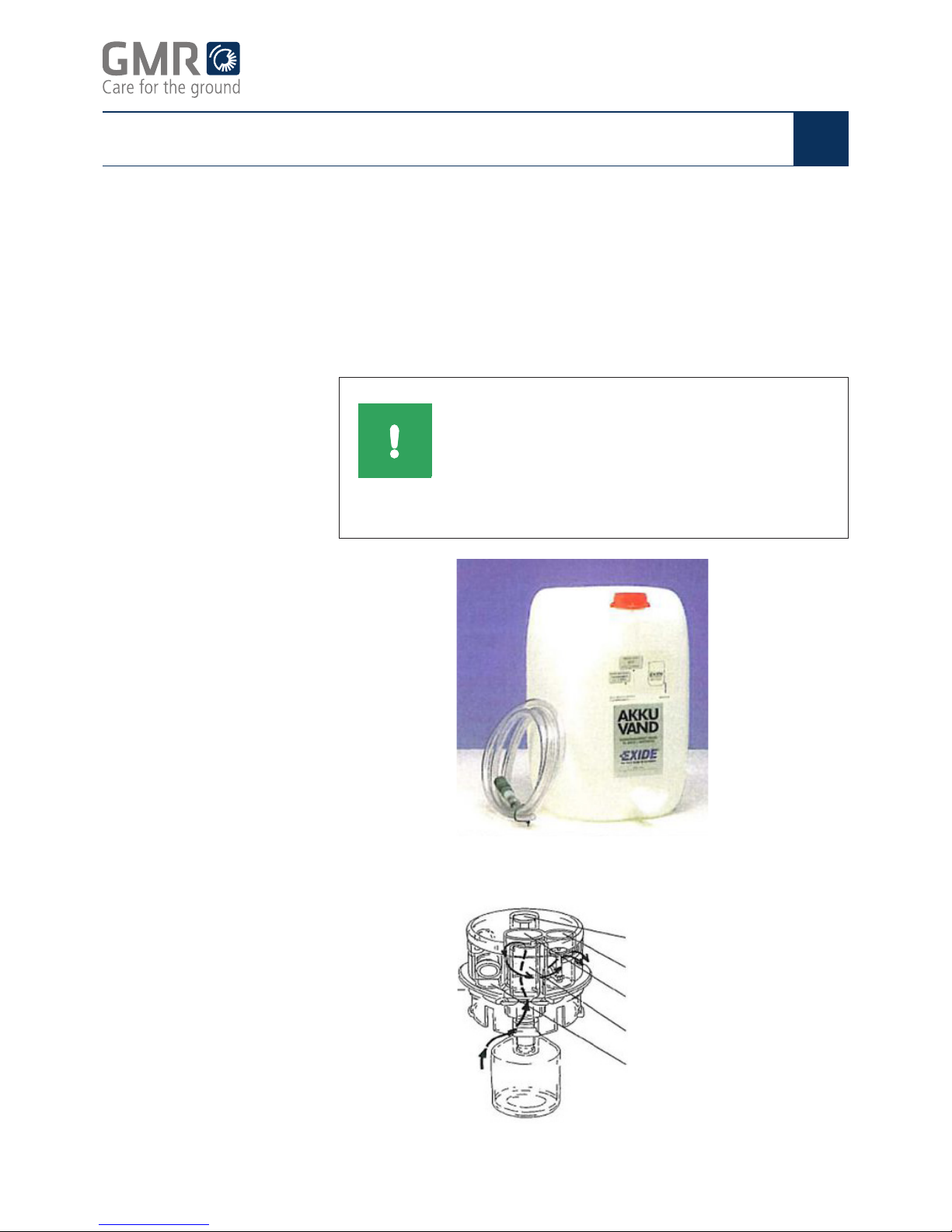
The battery lling system (BFS) caps work best when water pressure is
0.3-2.0 bar, which corresponds to water column pressure when pouring
from a height of 3-20 metres.
If the pressure is too low, the caps may fail to close at the correct level in
the cells and continue to ll. The battery will then overow, which affects
electrolyte density and may damage the battery box and underlay.
The canister must be placed at least three metres above the cell caps,
preferably higher.
T-cylinder for water connection
Degassing cylinder
Fluid cylinder
Valve cylinder
Indicator cylinder
Automatic top-up with a
BFS and water caniste
COMMENT
Important information
If a battery has overowed, the electrolyte level
must be regulated. This must be only be done by
Exide Batteriservice, Motive Force. Call +45 702 78
702. Contact GMR maskiner a/s to order electrolyte
regulation
Page 17

GMR maskiner a/s
STAMA Micro, Parker, Mini, Multi, Evo, Maxi EL
Normal operation
Page 17
Operating Instructions
GB
Position the canister at the correct height and check the BFS system
regularly. If you do not, your battery may get damaged.
The battery manufactur-
er's guarantee provisions
For further information about the different types of batteries,
click: http://www.gnb-nordic.com/anden-info/garanti/motive/
Page 18

GMR maskiner a/s
STAMA Micro, Parker, Mini, Multi, Evo, Maxi EL
Lithium batteries
Page 18
Operating Instructions
GB
The lithium battery pack contains a number of individual LFP cells. The
pack has a nominal voltage of about 3.3 V per cell. This is the safest
type of lithium battery on the market.
LFP batteries have a at discharge curve, i.e. the voltage remains at
about 3.2 V until the battery is about 80% discharged, after which the
voltage diminishes sharply. To minimise the risk of damage and prolong
the lifetime of the batteries, we recommend that they are never more
than 80% discharged.
LFP battery discharge curve at different temperatures
Voltage (V)
Discharged capacity (%)
LFP batteries have a longer lifetime than conventional lead-acid
batteries. They can withstand more than 3,000 70% depth of discharge
(DOD) cycles. The voltage of LFP batteries must not fall under 2.5 V
per cell. If voltage falls below this level, the cells may be irreparably
damaged.
Battery lifetime
The battery pack
(LFP = Lithium Ferro
phosphate)
Page 19

GMR maskiner a/s
STAMA Micro, Parker, Mini, Multi, Evo, Maxi EL
Lithium batteries
Page 19
Operating Instructions
GB
Battery management
system
BMS = Battery Management
System
The lithium-ion battery pack is tted with BMS, a system which monitors
the voltage in each individual battery cell. A combined battery sensor/
balancing unit is tted to the top of each cell.
The PCB is tted directly onto the cell's + and - terminals and has two
functions:
1. The board constantly monitors cell voltage so that it remains within
the permitted range (2.6-4 V). If voltage is within the permitted
range, a green diode lamp lights up, The unit's output signals to the
main monitoring system that everything is in good working order.
2. The unit also helps to balance the cells while the battery pack is
recharging. When the charge voltage exceeds 3.6 V, the unit starts
to deduct balancing energy from + to - , increasing to 1 ampere
when maximum voltage (4.0 CV) is achieved. When the PCB is
balancing (deducting power), a red diode lamp lights up (at the same
time as the green one). The red diode lamp on the sensors does not
signal that there is an error.
Stama trucks with reset
button (until 2014)
The PCB outputs are daisy chained and monitored by a
micro-controller-based (MCU) monitoring system.
Page 20

GMR maskiner a/s
STAMA Micro, Parker, Mini, Multi, Evo, Maxi EL
Lithium batteries
Page 20
Operating Instructions
GB
There are two diode lamps on the MCU:
The green diode lamp indicates that
there is a 12 V supply to the PCB.
As long as the monitoring circuit is intact, the MCU ensures that a small
12 V relay remains connected. The 12 V relay supplies all remaining
units which take energy from the battery, e.g. the key switches, main
and pump relays.
The MCU monitors the cell circuit. If the circuit is broken, the red diode
lamp ashes. After 10 seconds, the relay is disconnected and the red
diode lamp lights up.
The MCU is disconnected if the main switch is disconnected.
The red diode lamp indicates that the
monitoring circuit is broken, i.e. that
there is a problem with at least one of
the cells.
MCU diode lamps
A break in the MCU circuit can be caused by a cell with excessively
low voltage. If this is the case, recharge the battery. Press reset button
briey.
Resetting the MCU
Insufcient cell voltage
Open main switch If there is a break in the MCU circuit caused by the main switch having
been opened, just press the reset button briey. The truck does not
need recharging.
If the MCU is triggered during charging, the charging voltage may
be too high or the battery imbalanced. Try pressing the reset button
repeatedly.
If one of the red cell sensor diode lamps lights up much earlier than the
others, the voltage in this cell is too high. The cell may be damaged.
If the cell is damaged, contact GMR maskiner a/s.
Excessive charging
voltage or imbalanced
battery
Stama trucks with no reset
button (after 2014)
Stama trucks which do not have a reset button are tted with a simple
BMS, in which the MCU is replaced by a simple BMS relay, which
requires no resetting. If all the battery sensors light up green, the
BMS relay is activated and the machine can be started. If just one of
the sensors does not light up green, the relay is not activated and the
batteries will not be excessively discharged.
Page 21

GMR maskiner a/s
STAMA Micro, Parker, Mini, Multi, Evo, Maxi EL
Lithium batteries
Page 21
Operating Instructions
GB
The battery charger charges all the batteries serially and
simultaneously to a charge voltage of 3.65 V per cell. The charger
charges constantly until the desired voltage level is achieved. Then the
charge voltage is reduced until full starting voltage is achieved. The
starting voltage is maintained until the charger is switched off.
Before the charge voltage is reached, all the cell sensors' red diode
lamps should light up.
The battery pack is fully charged in seven hours.
Lithium-ion batteries should not be subjected to charge voltage over
a prolonged period of time because constant high charge voltage
reduces battery capacity. Disconnect the charger when the batteries
are fully charged.
During storage, the battery discharges 3% a month and, to avoid
reaching full depth of discharge, it must therefore be recharged at least
every six months. Lithium batteries are maintenance-free.
Lithium-ion battery charger
Lithium batteries can withstand frost, and can be used down to minus
20 °C, though with reduced capacity.
Cold
• If they are corroded, clean cell terminals with a dry brush.
• Keep electrical connections dry at all times.
If you have a question or need more information material,
contact GMR maskiner a/s.
COMMENT
Important information
To avoid irreparable damage, NEVER allow lithium
batteries to discharge completely.
CAUTION
Damage to machinery or attachments
Do not open the cells as this can ultimately
(worst case) cause irreparable damage.
CAUTION
Damage to machinery or attachments
Lithium batteries must be at least +5 ˚C before
they may be recharged. If colder batteries are
charged they can be permanently damaged.
Page 22

GMR maskiner a/s
STAMA Micro, Parker, Mini, Multi, Evo, Maxi EL
Lithium batteries
Page 22
Operating Instructions
GB
Battery indicator
If the word SYNCHRONIZE ashes in the display, the battery charge
level reading is invalid. This happens if the indicator has been
disconnected from the battery. Fully recharge the battery to ensure that
the indicator measures correct battery charge level. SYNCHRONISE
disappears from the display.
Displays
Battery
power
(voltage)
Current power
consumption
or charging.
Minus - is
consumption
Ampere hours
used since
charging
Battery
power
remaining (%)
Remaining
operating
hours at
current
consumption
Battery alarm The battery indicator is set to the relevant size of battery. This must not
be changed except by agreement with GMR.
When the batteries have only a few percent of full power remaining, the
indicator triggers an alarm ((%)), and the truck runs at reduced speed.
The truck should be recharged.
Like an electricity meter, the battery
indicator measures power entering
and leaving the lithium-ion battery.
The battery indicator also calculates
power reserves. The indicator is always
connected to the battery – even when
the main switch is OFF.
1. CHARGE: Recharge the battery!
2. Numerical eld
5. Battery charge level
6. Charging indicator
7. Battery alarm
8. Unit of measurement
9. SYNCHRONIZE: Battery indicator
is not synchronised correctly
10. Next view
11. Menu button (not normally used)
12. Previous view
Page 23

GMR maskiner a/s
STAMA Micro, Parker, Mini, Multi, Evo, Maxi EL
Care for the ground
www.gmr.dk
Type:
kW:
No.:
Kg.
Marking/labelling
Page 23
Operating Instructions
GB
The truck is marked with various labels and signs. These must remain
on the truck at all times. If labels and signs are damaged or obscured
by paint, they must be replaced.
New labels and signs are available from the manufacturer or
contact your dealer.
Warning signs The machine carries warning signs.
Labels and signs:
Type plate/serial
number plate machine number and
other specications
CE label The CE label indicates that the truck complies with the
EC Machinery Directive, and states production year.
Other labels The truck also carries the manufacturer's own labels (logos, etc.)
and a technical data label.
Page 24

GMR maskiner a/s
Side 24
STAMA Micro, Parker, Mini, Multi, Evo, Maxi EL
Operating Instructions
GB
Customer services and claims
Claims The warranty period on GMR machines is 12 months from the purchase
date, and covers any material or manufacturing defects. These parts
will be replaced by GMR maskiner a/s free of charge. Consequential
damage and wear and tear will not be replaced.
Any components which are not manufactured by GMR maskiner a/s are
included under the terms of the warranty to the extent authorised by the
supplier of the parts in question.
GMR maskiner a/s reserves the right to assign a claim of this kind
to the relevant supplier and not to reach a decision until the relevant
supplier has responded.
The following must be observed when working on a claim:
• report the claim to GMR maskiner before the repair is started
• agree a time period with GMR maskiner for qualied technicians to
carry out the repair
• any labour costs will only be approved at a xed net price.
If GMR maskiner a/s has not authorised repair work in advance, any
invoice submitted for repair work will not be approved.
At GMR maskiner a/s' request, before the claim can nally be handled,
any parts that were replaced must be sent carriage paid to the factory.
GMR maskiner a/s retains the exclusive right to determine the extent to
which a part shall be replaced or repaired.
The warranty does not cover:
• normal wear and tear or damage which has resulted from
inadequate maintenance.
• damage caused by collision.
• non-compliance with the product's technical specications or if the
product is used for a purpose other than that described in the user
manual.
If the product is altered or if non-original spare parts are used, all rights
under the warranty will be rendered void.
The purchaser does not have the right to require that design changes
on future models are implemented in a pre-existing machine.
Page 25

GMR maskiner a/s
Side 25
STAMA Micro, Parker, Mini, Multi, Evo, Maxi EL
Operating Instructions
GB
Customer services and claims
In the event
of a complaint:
Complaints must be registered directly with GMR maskiner a/s.
Complete a complaint report, stating the machine type, production
number and date of its delivery to the customer, and send it to us. This
is done via the dealer login on our website www.gmr.dk.
If questions arise about claims on imported machines, we reserve
the right to present the claim to the manufacturer before making any
decision about whether the claim can be accepted.
Our machinery is subject to the EC Machinery Directive and quality
assured within the European Union. We make every effort to comply
with these requirements and do our utmost to supply high quality
machinery.
Horsens, 01.06.2017
GMR maskiner a/s
Page 26

Copyright, GMR maskiner a/s ©
Saturnvej 17
DK-8700 Horsens
www.gmr.dk
01032018
 Loading...