

GM Pickup GMT900 C Installation Instructions Manual
BAER Your Complete Performance Brake Supplier!
Installation Instructions
Product: Rear GT disc conversion Instruction Part Number: 6000269
Vehicle
Make: GM Pickup
Model: GMT900 C or K10
Year(s): 2005>
Notices – Read and Follow BEFORE ATTEMPTING INSTALLATION
• All installations require proper safety procedures and protective eyewear.
• All installations assume basic mechanical skill and a factory service manual for the vehicle on
which the installation is to be performed.
• All references to LEFT side of vehicle always refer to the Driver’s side of the vehicle.
• Any installation requiring you to remove a wheel or gain access under the vehicle require s use of
jack stands appropriate to the weight of the vehicle. In all cases Baer recommends jack stands
rated for at least 2-tons.
• A selection of hand tools sufficient to engage in the installation of these products is assumed and
is the responsibility of the installer to have in his/her possession prior to beginning this
installation. All installations, which require removal of hydraulic hoses and/or bleeding of the
brakes, require appropriate fitting/line wrenches, as well as a safety catch can and protective
eyewear. Other than these items, if unique or special tools are required they are listed in the
section for that step.
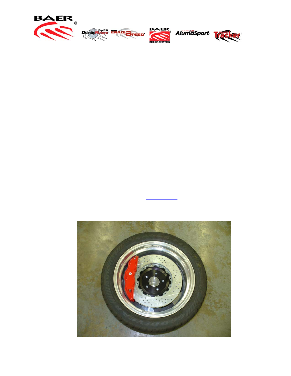
• ALWAYS CONFIRM WHEEL FIT PRIOR TO BEGINNING INSTALLATION OF ANY BRAKE
SYSTEM OR “UPSIZED” ROTOR UPGRADE! In addition to already having checked fit using the
Baer Brake Fit Templates available online at www.baer.com
assembly or a combination of the caliper assembly fit onto the rotor into the actual wheel to
reconfirm proper clearance is available between the caliper and the wheel before proceedi ng with
the actual installation.
, always place the actual corner
Baer, Incorporated 3108 W. Thomas Road, Suite 1201 Phoenix, Arizona 85017
Ph. (602) 233-1411 Fax. (602) 352-8445 Email. Brakes@baer.com
Page 1 of 4
www.baer.com
BAER Your Complete Performance Brake Supplier!
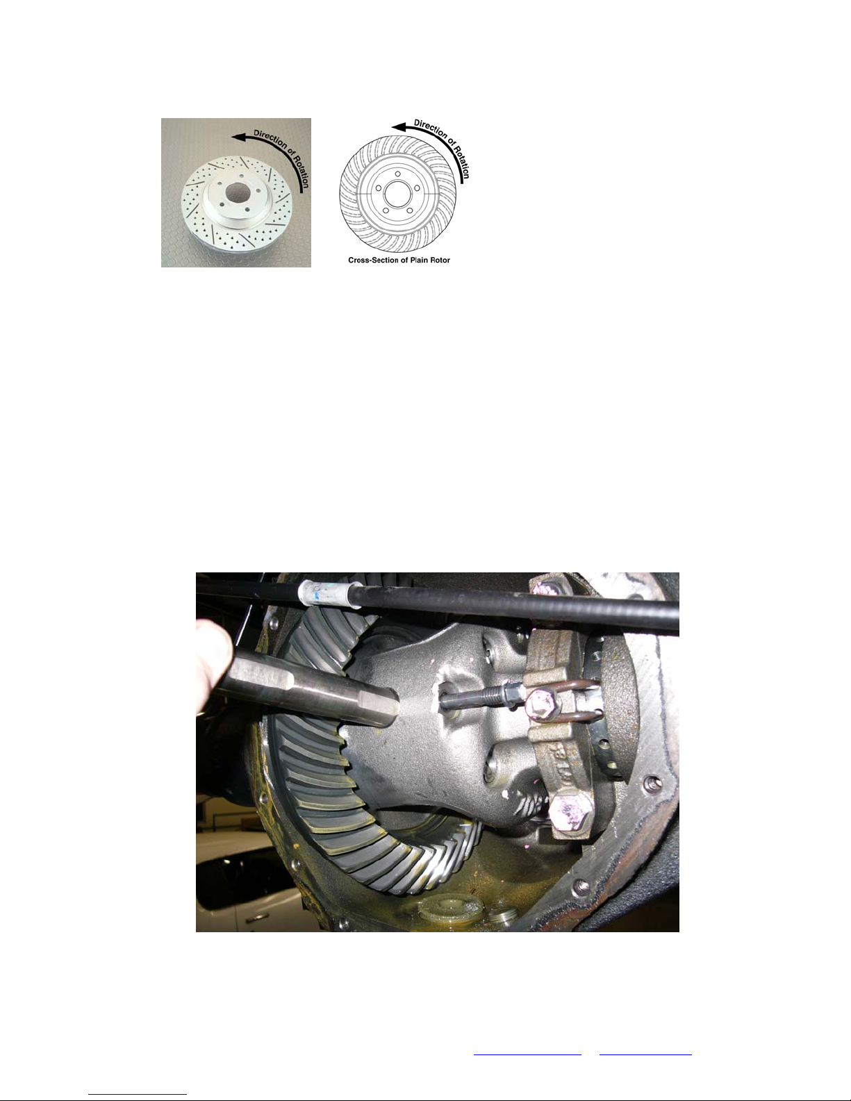
• When installing rotors on any Baer Products be sure to follow the direction of rotation indicated on
the rotor hat area with either
an arrow, or an “L” for left, or
an “R” for right, or both. “L” or
left, always indicates the
driver’s side of US spec
vehicles.
Images shown are “L” left
• A proper professional wheel alignment is required for any system requiring replacement of the
front spindles, or tie rod ends. Follow factory prescribed procedures and specifications unless
otherwise indicated.
• At all times stop the installation if anything is unclear, or the parts require force to install. Consult
directly with Baer Technical Staff in such instances to confirm details. Please have these
instructions, as well as the part number machined on the component that is proving difficult to
install, as well as the make, model, and year (date of vehicle production is preferred) of your
vehicle available when you call. Baer’s Tech Staff is available from 8:30-am to 5-pm Mountain
Standard Time (Arizona does not observe Daylight Savings Time) at 602 233-1411 Monday
through Friday.
Raise the truck and support with appropriate jack stands. Remove the differential cover. Locate and
remove the differential retaining pin. (see photo 1) Slide axles inward and remove c-clips. Slide axles
completely out of the housing using care not to damage axle seals
Disconnect both park brake cables. Disconnect fluid lines from backing plates and cap with supplied vinyl
caps.
Baer, Incorporated 3108 W. Thomas Road, Suite 1201 Phoenix, Arizona 85017
Ph. (602) 233-1411 Fax. (602) 352-8445 Email. Brakes@baer.com
Photo 1
Page 2 of 4
www.baer.com
 Loading...