

Page 1

2015. 06
User Manual for PROTOPICⅢ-540
PROTOPICⅢ-540 DUAL
Before you operate the product, this manual has to be read by operator.
※ External Design & Specification can be changed for improvement without any prior notice.
Page 2

INDEX
◐ SAFETY ◐ HOW TO LAMINATE
29~30 page
Important Safety Instruction 3~5 page
Safety Device 6 page
◐ MAINTENANCE
31 page
Warning Sticker 7~8 page
◐ TROUBLE SHOOTING
32~35 page
◐ INSTALLATION
Packing Contents 9 page
◐ SPECIFICATION
36 page
Main Devices 10 page
How to move & install 11~13 page
◐ DIGITAL SLEEKING SOLUTION
DIGITAL SLEEKING SOLUTION 소개 37 page
◐ HOW TO USE CONTROL PANEL
GLOSS & MATT SLEEKING
38~41 page
Explanation of Control Panel 14~16 page HOLOGRAM SLEEKING 42~45 page
Explanation of Display 17~19 page METALLIZE PRINTING 46~47 page
Error Message 20~21 page SLEEKING FOIL SPECIFICATION 48 page
◐ MAIN DEVICES
Lamination 22~25 page
Cutting 26 page
How to load / replace film roll 27 page
Other Devices 28 page
Page 3

IMPORTANT SAFETY INSTRUCTION
"Instruction for Safety" is for the purpose of user's safety
and prevention of Property loss. Read thoroughly and Use rightly according to the manual
Important Safety Instruction is classified as "Warning" and "Caution", the meaning is as follows;
Warning : If you ignore this symbol, you could suffer serious injury or death
Caution: If you ignore this symbol, you could receive a serious injury or loss of property
This symbol means a prohibited action. If you ignore a prohibited action, you could suffer a personal injury and damage the machine
This symbol means a required action. If you don't follow this action, your safety is not guaranteed.
Required action will be included in this symbol.
Reference: The sign above refers the contents for user's safety and prevention of Property loss.
3/48
Page 4
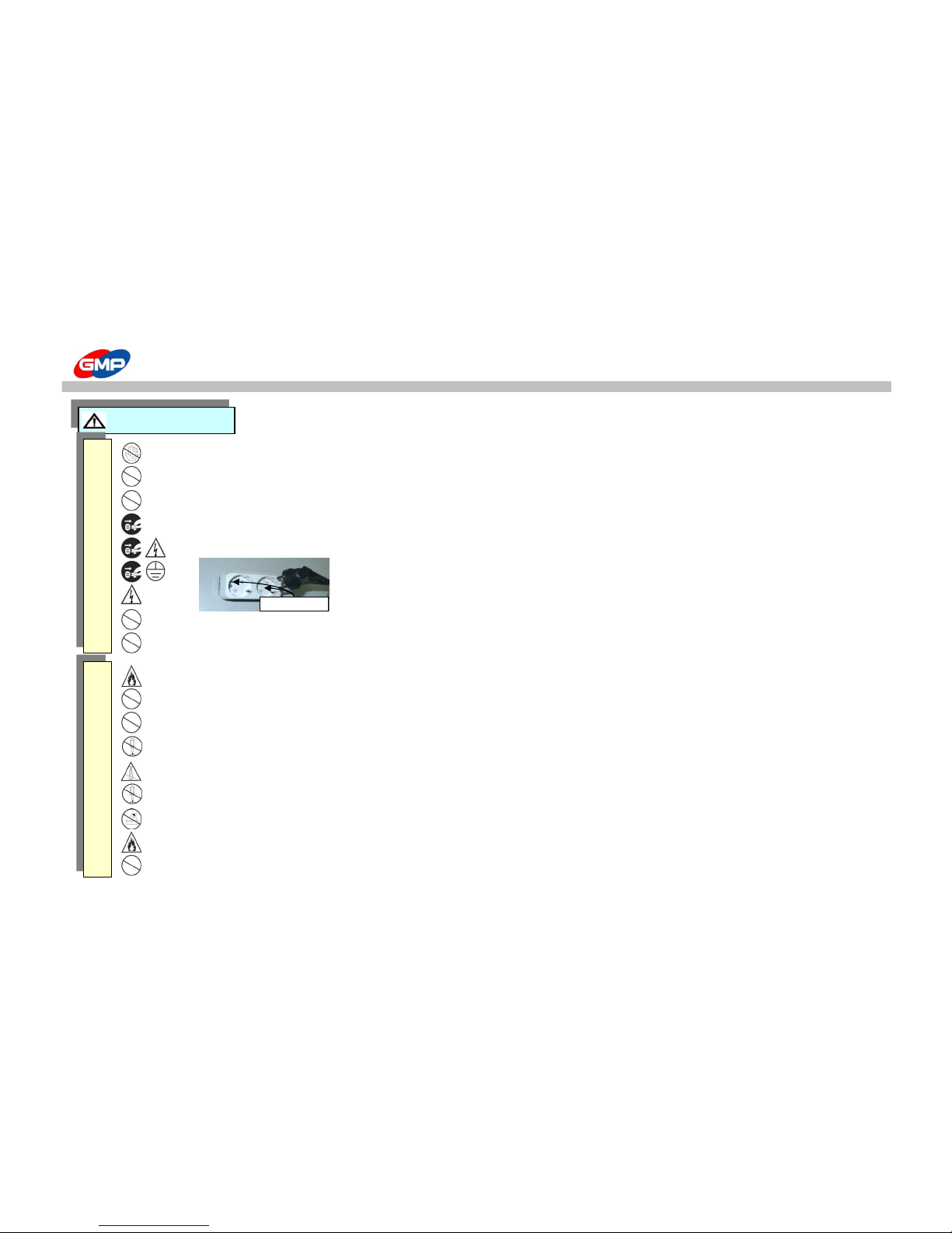
IMPORTANT SAFETY INSTRUCTION
Do not connect or disconnect with wet hands, as this will cause an electric shock
Do not overload a power supply, as this will cause a fire and an electric shock.
Do not use a damaged plug or lead, as this could cause a fire or an electric shock
Do not use other voltage and power supply other than specified, as this will cause a fire and an electric shock.
Make sure plug is in the socket, as it could cause fire or an electric shock
Grounding is needed for your safety
A malfunction and losing electricity make an electric shock
Danger, Malfunction, loss of electricity could cause an electric shock
Do not pull the plug or bend improperly
Do not use materials near a naked flame
Do not use the machine in the sealed place.
Only use the specified power and voltage. It can be a reason of fire flame or an electricity fire flame.
Do not dissemble, make repairs or convert the machine. Contact your dealer for repairs
Ensure all hair, neckties, necklaces, are kept free of the feeding table to avoid injury
Do not convert the safety device and safety switch.
Do not spill any liquids on the laminator as this will cause damage and a possible electric shock
Do not use the flammable spray or flammable materials inside or outside the machine. As this could cause a fire.
Do not allow children use of this equipment
WARNING
GROUNDING
P
O
W
E
R
I
N
S
T
A
L
L
A
T
I
O
N
4/48
Page 5
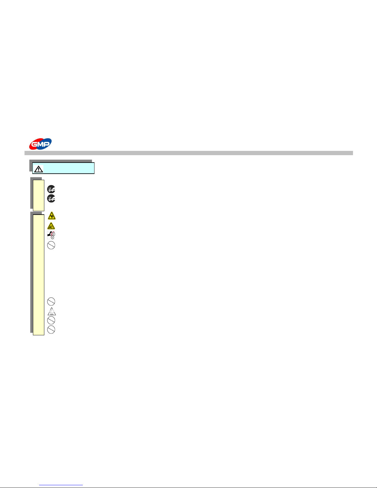
IMPORTANT SAFETY INSTRUCTION
When moving the product, turn off the power switch, disconnect the power plug from the socket
When laminator is not in use, you must turn off the power switch, disconnect the power plug from the socket.
More than 2 people are needed to carry this equipment to avoid personal injury or damage to the machine.
Keep gears and chains free of all materials
Do not touch the roller with your hand as you could be burnt.
Please avoid installing near the following places;
Gas stove, Ventilator or Air conditioner due the higher temperature or higher humidity
Do not place any materials on the laminator as they could catch a fire
Avoid the direct sunlight for the installing the machine
Make sure no vibration and dusts are found in the place during the installation.
Avoid the dark and slope place for installation
Do not place any materials on the laminator as they could catch a fire
Do not touch the film and laminating machine just after lamination finishes as you could be burnt.
Use the machine with laminating purpose only.
Tidy up the place near the laminating machine.
CAUTION
P
O
W
E
R
I
N
S
T
A
L
L
A
T
I
O
N
5/48
Page 6
SAFETY DEVICE
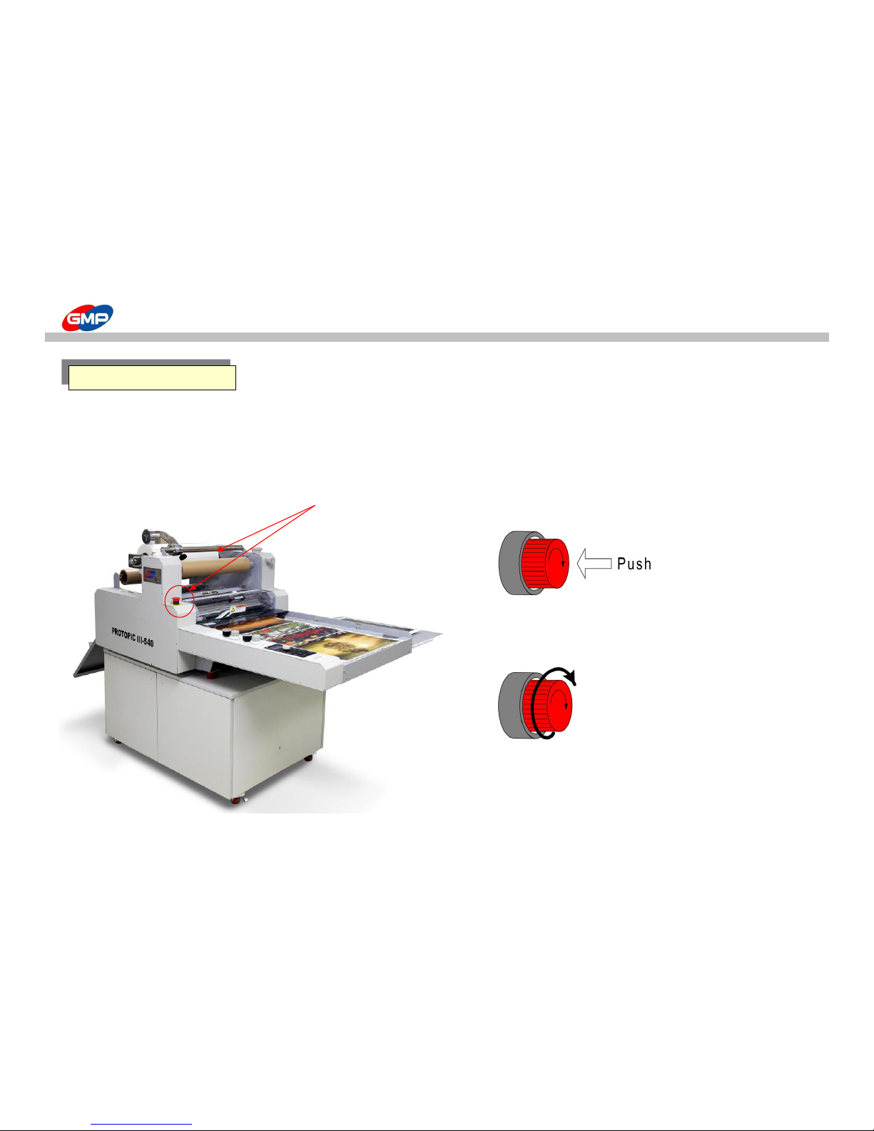
☞ Emergency Stop Switch (E-STOP S/W)
When emergency situation happened, it stops the running motor(rollers) rotation and system operation.
In case of emergency, use this switch.
☞ Position of E-Stop Switch ☞ How to use
Press the Red button to operate the Emergency Stop Switch.
All system is stopped when this is pressed.
Turn the switch to the right to release from Emergency Status.
Emergency Stop Switch
E-STOP S/W
6/48
Page 7
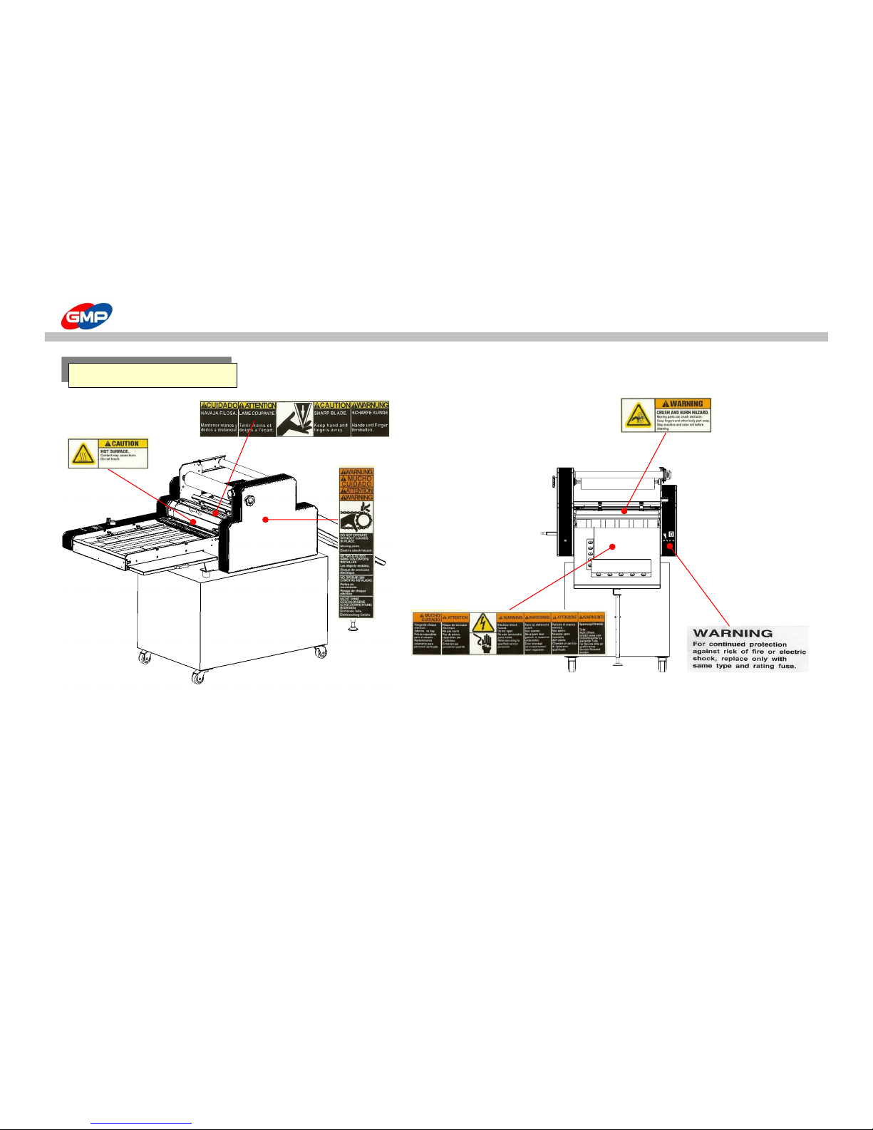
WARNING STICKERS
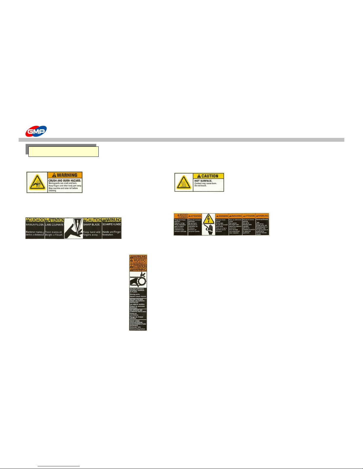
For the user safety, in the outer design, the below sticker is attached. Be cautious not to injured during operation.
☞Roller caution ☞ Higher Temperature
Do not touch the roller and heating plate with your hand as you could be burnt.
Do not touch on the heating part
Roller's higher temperature and press can damage your body
☞ Electricity Caution
☞Cutting Caution
Inside the machine, high voltage flows,
Do not touch your body on the trimming device Do not open the outer case
You can suffer an injury
You can suffer injury or sudden death with electricity shock
☞Chain Caution
Do not your body wound into a chain.시오.
You can suffer an injury
Warning Stickers
7/48
Page 8
WARNING STICKERS
Warning Stickers
8/48
Page 9
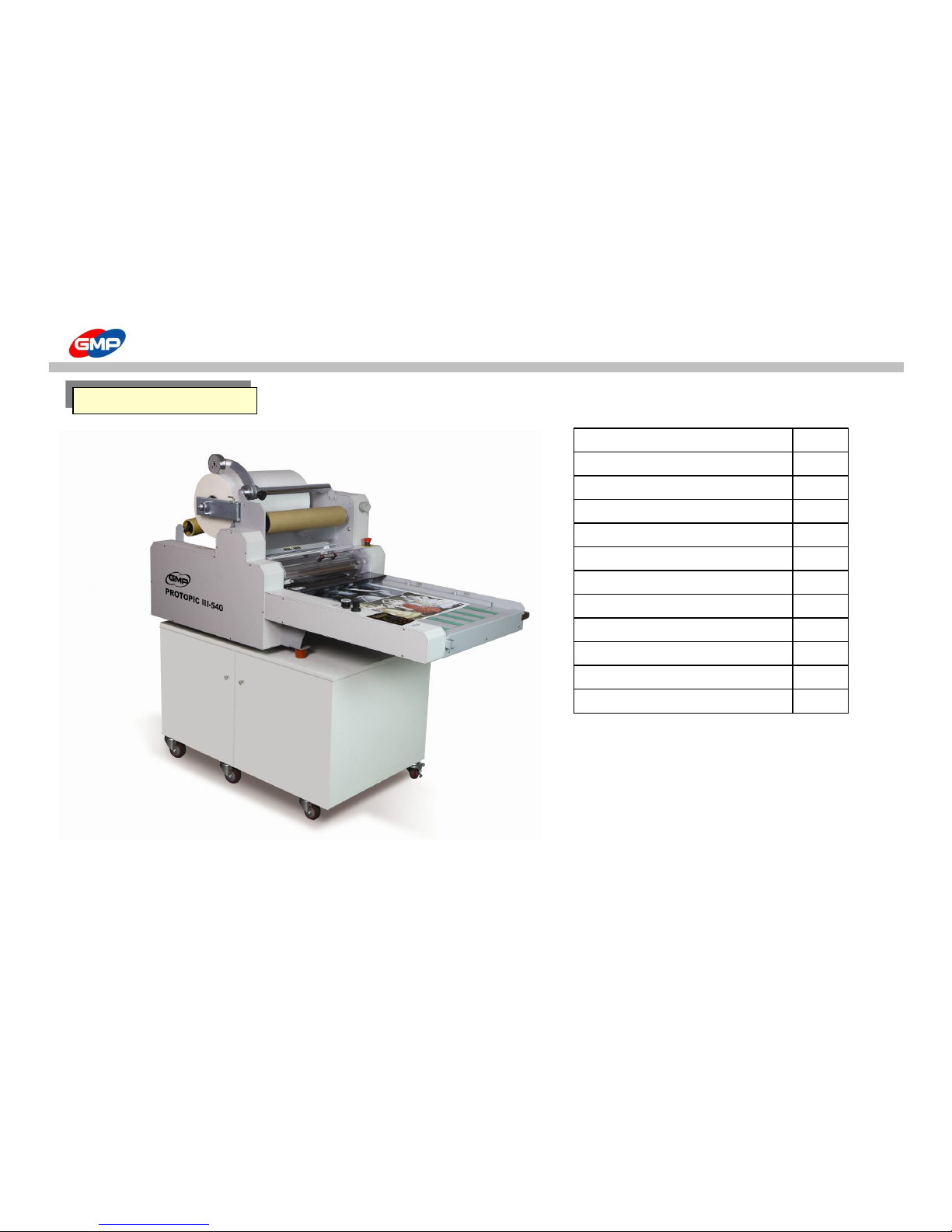
PACKING CONTENTS
ITEMS Q'TY(EA)
LAMINATOR 1
FEED TABLE 1
FEED TABLE GUIDE 2
AIR COMPRESSOR 1
AIR HOSE 1
GLASS TUBE FUSE (20mm) 250V/12.5A 4
GLASS TUBE FUSE (20mm) 250V/15A 2
WRENCH SET 1
LAMI TABLE 1
USER MANUAL 1
SEPARATOR IDLE ROLLER 1
`
Packing Contents
PROTOPIC III-540
9/48
Page 10
MAIN DEVICES
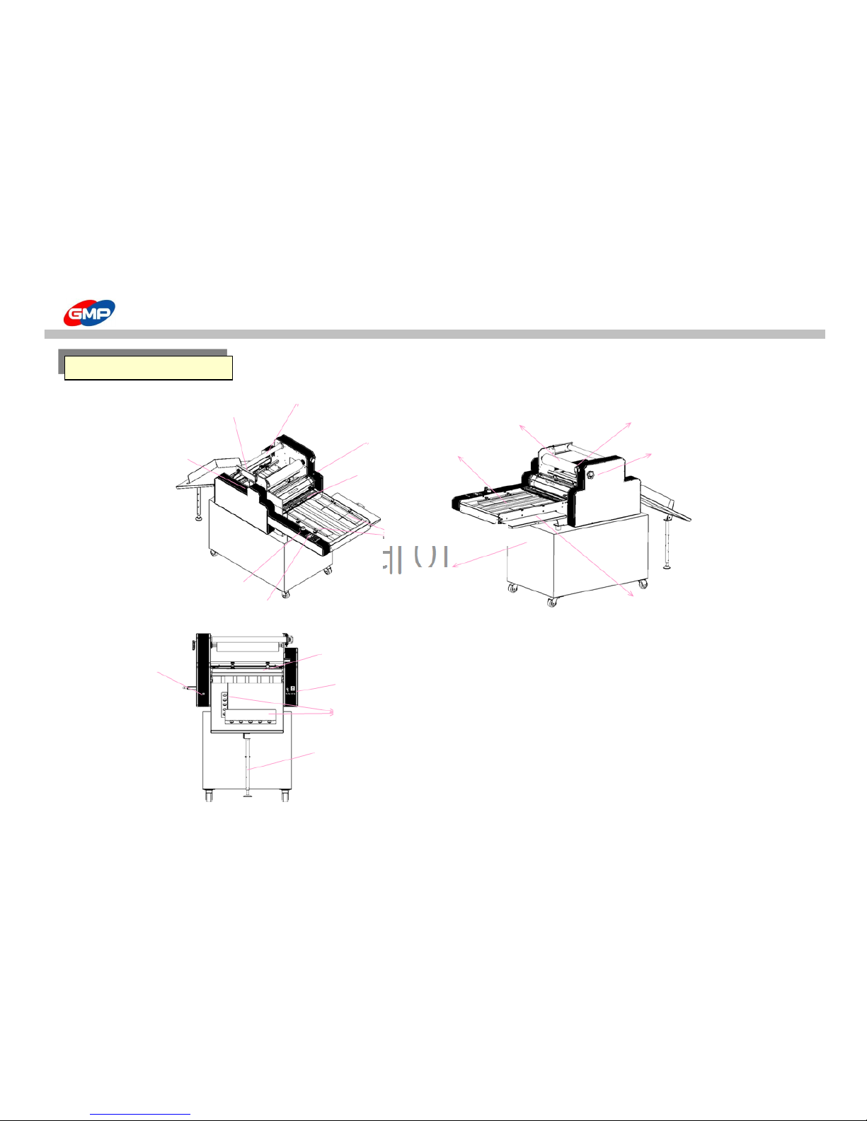
Main Devices
Film Shaft
Holder
Film Shaft
Decurling
Adjustment
Knob
E-Stop S/W
Feeding Gate
Paper Guide
Pull Roller
Pressure
Adjustmen Kob
Control Panel
Feed Table
Rewinder
Film Tension Adjustment Knob
Rewinder Tension
Adjustment Knob
Lami Table
Sub-Paper Table
Main Air
Bursting Roller
Power Board
Tray Paper Guide
Height Adjustable Foot for Tray
Table
10/48
Page 11
HOW TO MOVE & INSTALL
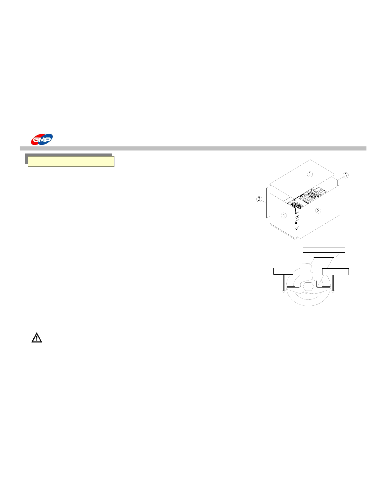
☞ HOW TO UNPACK
1. For rust prevention purpose, vacuum packing with aluminum materials is applied to the machine packing.
and the machine is additionally packed in wooden crate. Each wooden plate of the crate is fixed by
screws to avoid external shock.
2. Wooden Crate can be opened by 11mm Box Spanner.
As on the right picture, dismantle the crate and remove the vacuum packing to move it for installation.
☞ HOW TO MOVE
◑ In the below situation, the forklift is required for moving.
1. If the machine would be moved on the uneven surfaced ground.
2. If the machine has to be moved by 10m or longer distance.
3. If the packing is removed for moving.
◑ This bellows are for use of casters for moving.
1. If moving distance is shorter than 10m in the same place of installation.
2. At least 4 persons are required for moving. Push the corner of the machine gently & slowly.
☞ EXPLANATION OF CASTER WHEEL
To move the machine in the same place (short moving).
Caster has its locking device. Then, for moving, it has to be released from the locking status.
To lock or unlock, press "ON(Lock)" lever or press "OFF(Unlock)" lever.
After moving is done, press "ON" to fix the machine.
WARNING : The product is heavy, then be careful to move the product to avoid injury or damage of the product.
- Weight for PROTOPIC III-540(DUAL) : 170㎏s (190㎏s), Weight for LAMI TABLE : 75㎏s
UNPACK & INSTALLATION
잠김(ON)
풀림(OFF)
UNLOCK(OFF)
LOCK(ON)
11/48
Page 12
HOW TO MOVE & INSTALL
☞ Circumstance for Operation of Product
1. The product has to be installed on the hard & even surfaced ground.
2. If inflammables / ignition materials would be nearby the product, this could be a cause of fire.
3. To emit a heat in lamination, the installation place has a good ventilation.
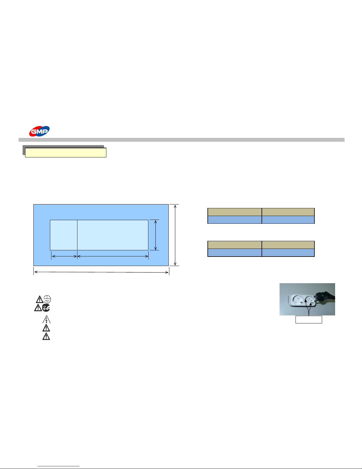
☞ Floor Plan
* PROTOPIC III - 540
- Height including Lami Table : 1340mm
* PROTOPIC III - 540 DUAL
- Height including Lami Table : 1340mm
※ Installation Space is different from its working circumstance.
☞ Power Connection
Power has to be at AC 220~240V/12A / Plug-in at Independent Outlet
WARNING : Grounding is required for safety. Otherwise, this could be a cause of malfunction or electric shock.
WARNING : Do not plug the product with the other devices at 1 outlet at the same time.
Otherwise, this could be a cause of fire by overheat at outlet.
WARNING : Please keep the specification of power / voltage. Otherwise, this will be a cause of fire & electric shock.
WARNING : Inset the power plug inside firmly. Otherwise this will be a cause of fire by overheating at outlet.
WARNING : The socket-outlet shall be installed near the equipement and shall be easily accessible.
Dimension (WxLxH)
Working Space (WxL)
Dimension (WxLxH)
Working Space (WxL)
800*1580*670mm
900*2350
800*1820*670
900*2590
잠김(ON)
풀림(OFF)
LAMINATOR
1580 (1820)
2350(2590)
900
Tray
Table
670
Grounding
INSTALLATION
12/48
Page 13
HOW TO MOVE & INSTALL
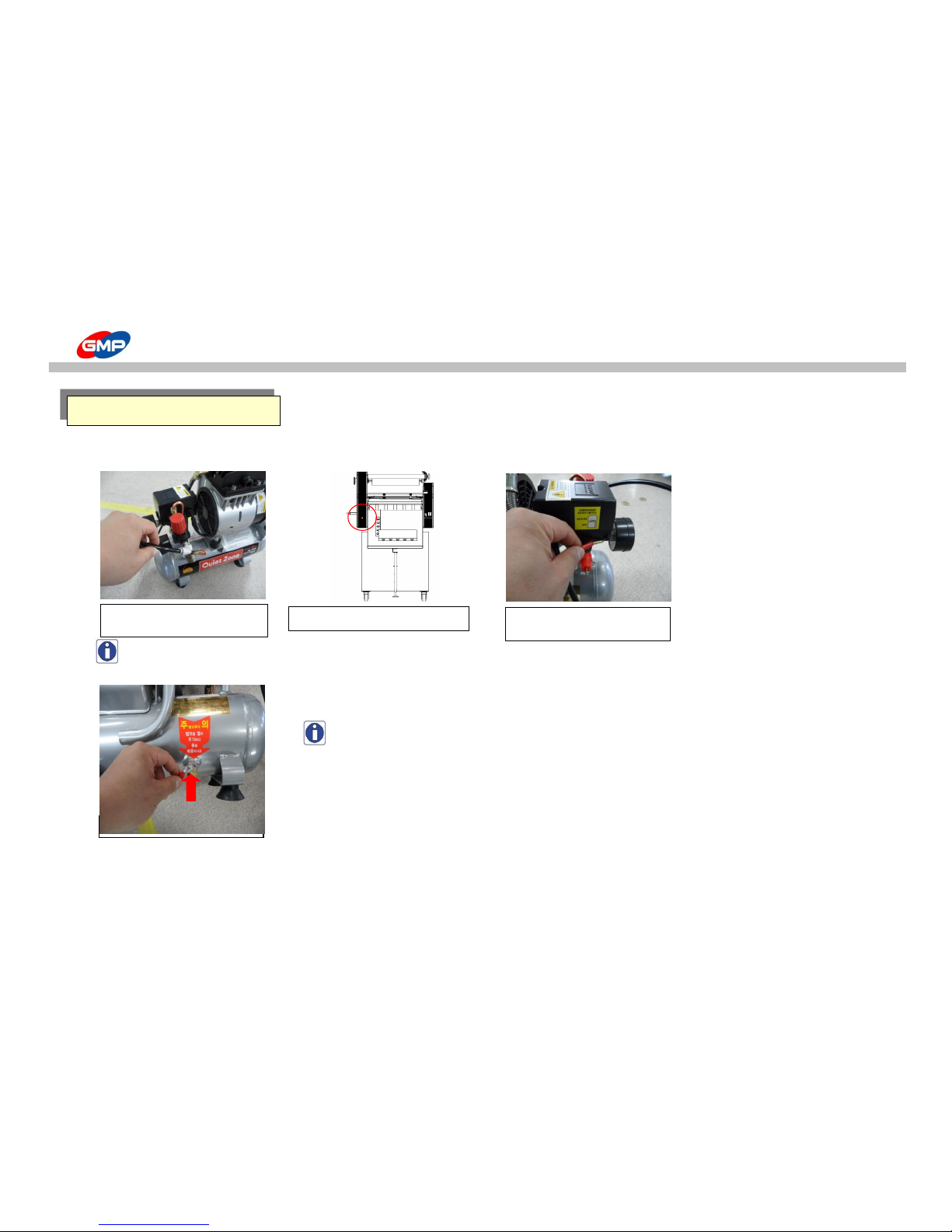
☞ How to connect
Compressed air needs to be supplied into the laminator to activate the bursting roller and pressure on the laminating roller.
NOTE : It is recommended to place the air compressor at outside of the laminator.
If this would be in the LamiTable, this will bring a short lifespan by high heat.
NOTE A large amount of moisture (water) is produced from the compressor during its operation.
For dry filter, it is necessary to remove such moisture (water), at least, 1time per a day.
잠김(ON)
풀림(OFF)
Connection for Air Compressor
화살표 방향으로 눌러주십시오.
Insert air hose in to the air
compressor
Connect the air hose to the laminator
Plug in at Independent Power
System
13/48
Page 14
HOW TO USE CONTROL PANEL
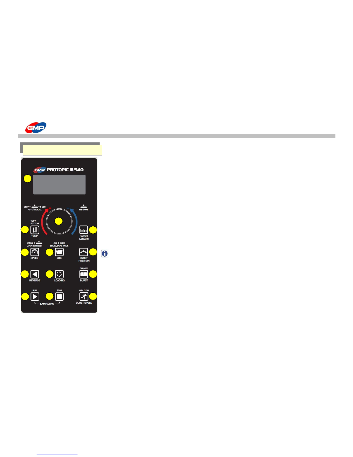
A. "LCD"(Display)
To display the setting values in the laminator.
When the Power is ON, LCD is lighted on.
Refer to the "Explanation of Display" for each displays.
B. "MASTER DIAL"
Dial to adjust values of Roller Temp.(C), Paper Length(D), Laminating Speed(E), Job Mode(F), Bursting Point(G), etc.
☞ How to use of MASTER DIAL
1. Press a button to adjust a required value.
2. Turn "MASTER DIAL" to left / right to set up for required setting value.
Turn "MASTER DIAL" to right to increase the value and turn it to left to decrease the value.
☞ Other Functions of MASTER DIAL
1. While the "MASTER DIAL" is pressed, the current temp. is displayed.
2. Press SPEED button and MASTER DIAL at the same time, it makes COUNTER RESET.
3. Press STOP button and MASTER DIAL at the same time for 5 secs. to change the mode to AUTO or to MANUAL.
NOTE : AUTO MODE is to integrated with GMP Automatic Feeder of PROFEEDR-5478. (Contact GMP to purchase it.)
C. "TEMP"(Button to set up the Roller Temp.) :
To set up the Roller Temp. Temp. Setting Range is "0 ~ 150"℃ .
☞ How to set up the MIRROR Roller Temp. :
Press "TEMP" button to "ON" and set up a required temp. with "MASTER DIAL".
☞ How to set up the Embossing Roller Temp. (PROTOPICIII-540DUAL) :
In normal status (SINGLE MODE), no power is supplied to the Embossing Roller Heater.
To heat up the Embossing Roller, change the mode to DUAL MODE.
1. Press "JOB" button for more than 3 secs. to change it to "DUAL" mode.
2. Press "TEMP" button to "OFF" and set up a required temp with "MASTER DIAL".
The set up value is saved automatically after 5 secs.
C
E
H
K
D
G
F
I
J
A
B
L
M
CONTROL PANEL
14/48
Page 15

HOW TO USE CONTROL PANEL
D. "PAPER LENGTH"(Button to set up Paper Length) :
To set up the length of substrate.
Length set up range for MANUAL MODE is "203 ~ 1,219"mm and for ATUO MODE is "254 ~ 813"mm.
☞ How to set up Substrate Length :
Press "PAPER LENGTH" button and set up a required length with MASTER DIAL. Setting value is saved after 5 secs. automatically.
NOTE : This product has "UNDERLAP" cutting system. Then, setting value has to be smaller than real size by 3~5mm for under lapped area.
E. "SPEED"(Speed Setting Button) :
To set up the laminating speed. Speed setting range is "1 ~ 15".
☞ How to set up Speed : Press "SPEED" button and adjust speed with MASTER DIAL.
F. "JOB"(Job Mode Selection Button) :
Save regularly used job conditions at the memory to avoid reset the conditions in future.
Job mode is composed of 13 kinds (Poly-L~User3).
☞ Select a Job Mode : In stop status, press "JOB" button and select a required job mode for films with "MASTER DIAL".
Temp., Substrate length can be saved by operator and this value is saved automatically after 5 secs.
☞ Other functions of "JOB" button : Press JOB button for 3 secs., mode can be changed to SINGLE or to DUAL mode.
"DUAL" mode is required in PROTOPIC III-540DUAL to heat up the Embossing Roller.
NOTE : Factory Setting Progress
In "Poly-L" Mode, press "TEMP" button and "STOP" button at the same time, message of "Factory Setting Progress Waiting" is blinking and displaying
for around 15 secs. After on, the setting value in JOB mode is changed to Factory Setting Values.
15/48
Page 16

HOW TO USE CONTROL PANEL
G. "BURST POSITION"(Set up button for the Bursting Point) :
To set up operation point of Bursting Roller. Bursting Point range is "580 ~ 660"mm (for DUAL : "760 ~ 840"mm).
☞ How to set up Bursting Point :
Press "BURST POSITION" button and set up its position with MASTER DIAL. The set value is saved automatically after 5 secs.
NOTE : Characteristics of materials / thickness, height of decurling bar, laminating speed make bursting point change, then,
adjust it for its cutting status. Basically, the range is 610 ~ 620 (for DUAL : 790 ~ 800).
H. "REV"(Button to Reverse Rotation of Roller) :
To rotate the roller reversely. While the "REV" button is pressed, the roller is rotated reversely in roller engaged status.
Then, the button is not pressed, reverse rotation is stopped and rollers are disengaged.
NOTE : During the machine operation, the function is not activated.
I. "LOADING"(Button for Film Loading & Setting) :
To set the machine initially and to load a film roll.
While "LOADING" button is pressed, roller is rotated and feeder is opened for feeding.
NOTE : During the machine operation, the function is not activated.
J. "BURST"(Button to operate Upper Bursting Roller) : To move Bursting Roller to up/downwards.
Press "BURST" button to light on. Then, the Bursting Roller starts to move. Press the button again and lamp is OFF, the Bursting Roller is stopped to move.
NOTE : Only in RUN status, the button is activated. In STOP status, the button is not activated.
K. "RUN"(Operation Button) : To operate the machine. Press "RUN" button to operate roller with engagement.
NOTE : If the roller rotates fast from stop status, this could be a cause of error in job.
L. "STOP"(Stop Button) : Stop the machine operation. Press "STOP" button to stop roller and the rollers are disengaged.
M. "BURST SPEED"(Button to operate Lower Bursting Roller in high speed) :
To make the lower bursting roller in high speed during lamination for NYLONEX(NYLON) & PERFEX(PET) films to increase its cutting quality.
Press "BURST SPEED" button and its lamp is ON, the lower bursting roller is rotated in high speed. Then, press the button and the lamp is OFF,
the roller is rotated in normal speed.
16/48
Page 17
HOW TO USE CONTROL PANEL
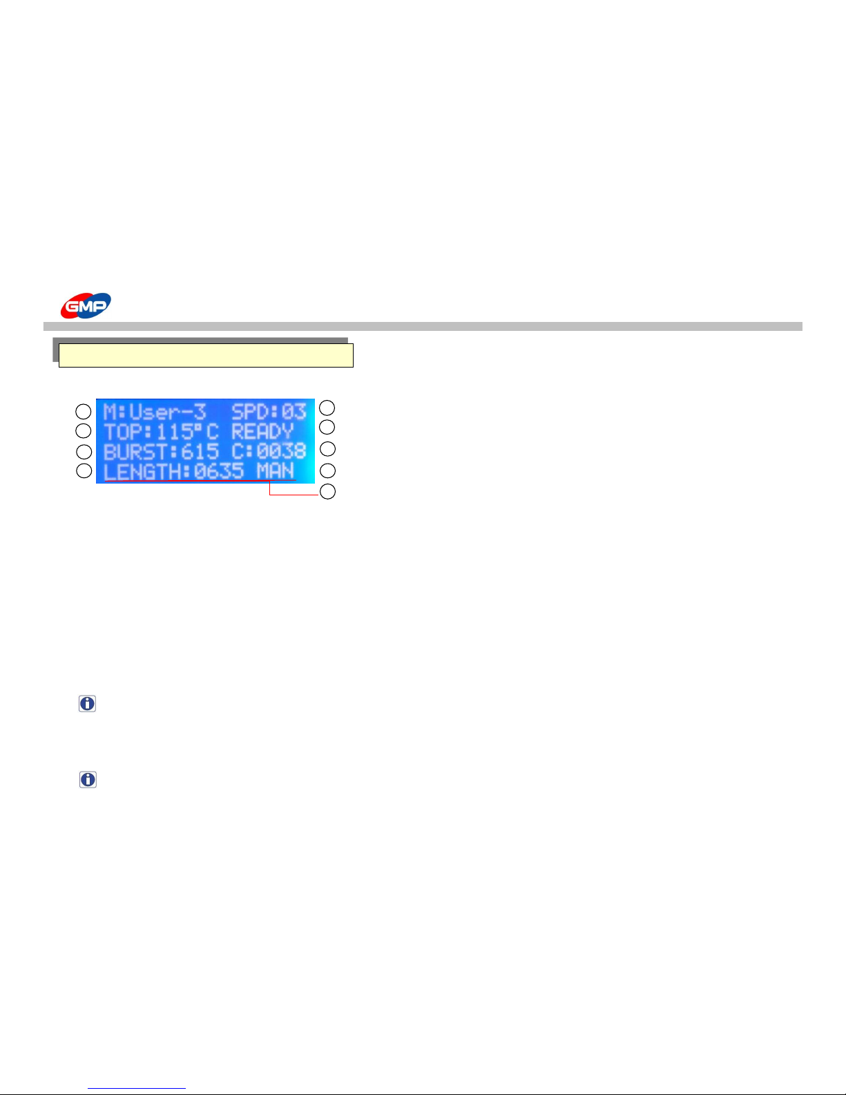
Job condition, Setting Status and Machine status are shown on the display.
1. Job Mode 6. Job Mode
2. Roller Temp. 7. Counter
3. Paper Bursting Timing 8. Feeding System
4. Paper Length 9. Error Message
5. Roller Speed
① "M:User-3" - Job Mode Display
To save a setting values that are made by operator for different conditions.
Job mode is composed of the below 13 modes.
JOB MODES
- Poly-L : Lower Temp. for Polynex Film (Set Temp. 100℃)
- MICRO : Micronex Film Lamination (Set Temp. 120℃)
- Poly-H : Higher Temp. for Polynex Film (Set Temp. 120℃) - FOIL-L : Lower Temp. for Foil Film (Set Temp. 115℃)
- Nylon : Nylonex Film Lamination (Set Temp. 115℃) - FOIL-H : Higher Temp. for Foil Film (Set Temp. 125℃)
- PET-L : Lower Temp. for Perfex Film (Set Temp. 100℃)
- User-1 : Operator Set up Mode 1
- PET_H : Higher Temp. for Perfex Film (Set Temp. 120℃)
- User-2 : Operator Set up Mode 2
- FUS-L : Lower Temp. for Sleeking Foil (Set Temp. 125℃)
- User-3 : Operator Set up Mode 3
- FUS_H : Higher Temp. for Sleeking Foil (Set Temp. 135℃)
NOTE : Refer to the "JOB" to check the setting value and how to save.
② "TOP:115℃ - Temp. Display
To display set temp. and current temp. for laminating roller. Set Range is "0~150℃".
☞ How to check the current temp. : While "MASTER DIAL" is pressed, the current temp. is displayed.
NOTE : Refer to the Temp in Explanation of Control Panel to set up.
Explanation of Control Panel (PROTOPICIII-540)
[PROTOPIC III-540]
2
4
8
5
6
7
3
1
9
17/48
Page 18

HOW TO USE CONTROL PANEL
③ "BURST:615" - Bursting Timing Display
Operation point for Bursting Roller. Bursting Point range is "580 ~ 660"mm (for DUAL : "760 ~ 840"mm).
NOTE : Refer to he Explanation of Control Panel to set up the Bursting Timing.
④ "LENGTH:0635" - Paper Length Display
Displayed value means paper length. Then, put a length for lamination.
Its setting range is (for MANUAL MODE : "203 ~ 1,219"mm) (for AUTO MODE : "254 ~ 813"mm).
NOTE : Refer to the PAPER LENGTH in Explanation of Control Panel to set up.
⑤ "SPD:03" - Roller Speed Display
To display Laminating Roller Speed. Its setting range is "1 ~ 15".
NOTE : Refer to the SPEED in Explanation of Control Panel to set up. In initial job, start at lower speed.
⑥ "READY" - Roller Temp. Display
To display Ready for Lamination. It displays "WAIT" or "READY".
- "W"(WAIT) : Not suitable for lamination(Temp. is higher or lower for lamination).
- "R"(READY) : Good for lamination. Start lamination.
⑦ "C:0038" - Counter Display
Counter for sheet for a certain time period. It can be reset if it is required.
☞ Counter Reset : Press "SPEED" button & "MASTER DIAL" button at the same time or turn off the power and turn it on again.
But, the previous data is not saved.
⑧ "MAN" - Feeding Display
To show feeding method. This is composed of "MAN"(Manual Feeding) & "AUTO"(Automatic Feeding).
NOTE : To change the feeding method, refer to the MASTER DIAL in Explanation of Control Panel.
⑨ Error Message Display
When error is occurred, if the RUN button is pressed, a message is displayed. In this status, the machine cannot be operated.
NOTE : Refer to the Error Message for display.
18/48
Page 19
HOW TO USE CONTROL PANEL
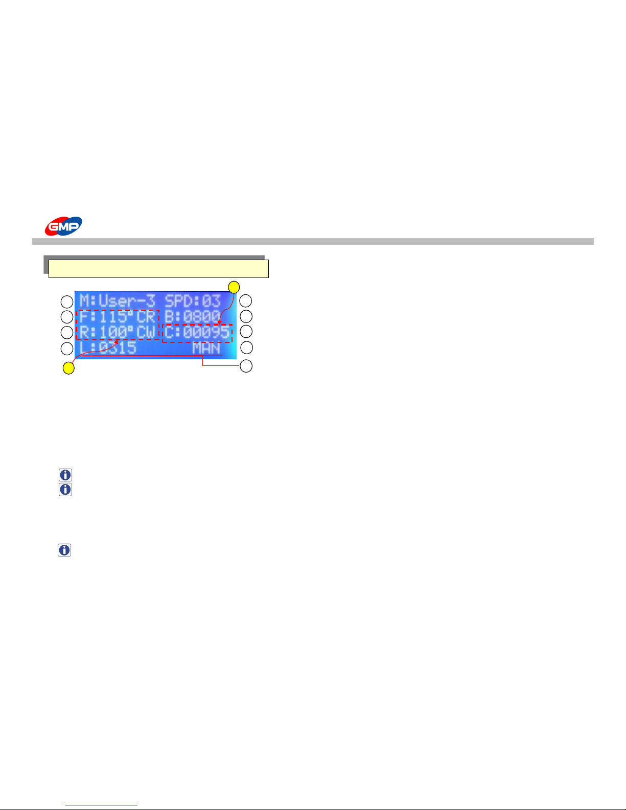
1. Job Mode 6. Bursting Timing
2. MIRROR Roller Temp. & Status 7. Counter / Roller Heating Mode
3. EMBO Roller Temp. & Status 8. Feeding Method
4. Paper Length 9. Error Message
5. Roller Speed
Refer to the Explanation of Display for PROTOPIC III-540 for normal conditions.
A. "F:115℃R , R:100℃W" - Roller Temp. & Status Display
MIRROR Roller & EMBO Roller Temp. & its Status.
- F:115℃R : MIRROR Roller Set Temp. & its Status
- R:100℃W : EMBO Roller Set Temp. & its Status
NOTE : Ready for Lamination status with display of W"(WAIT) or "R"(READY).
NOTE : Press "MASTER DIAL" to display the current temp. & the roller heater power supply status.
B. Counter Display / Roller Heating Mode Display
To display the power supply status for heater on MIRROR Roller and EMBO Roller.
There are "SINGLE" mode and "DUAL" mode, in "SINGLE" mode, EMBO roller has no heat although temp. is set up.
NOTE : Refer to TEMP in Explanation of Control Panel to change mode.
[PROTOPIC III-540 DUAL]
2
4
8
5 6 7
3
1
9
Explanation of Display (PROTOPICIII-540DUAL)
A
B
19/48
Page 20

ERROR MESSAGE
☞ "EMS & COVER OPEN!!"
This is displayed when Roller Safety Cover is opened or when E-STOP Switch is pressed.
In emergency case, the switch makes Roller operation and System stop.
Roller Safety Cover is to avoid burn from contact to high temp. roller
Then, keep this in close status except film loading.
After the cover is closed and make the switch release to back to normal.
NOTE : This message is shown for 3 secs. as the RUN is pressed.
☞ "S-opn"
Temp. Sensor is short or Contact between Slip Ring & Brush is not good, the message is displayed.
As this message is displayed, check the mentioned parts.
WARNING : Power has to be "OFF" to check the mentioned parts.
Roller Cover
E-STOP S/W
Release E-STOP S/W
Error Messages
Brush
Slip Ring
20/48
Page 21
ERROR MESSAGE
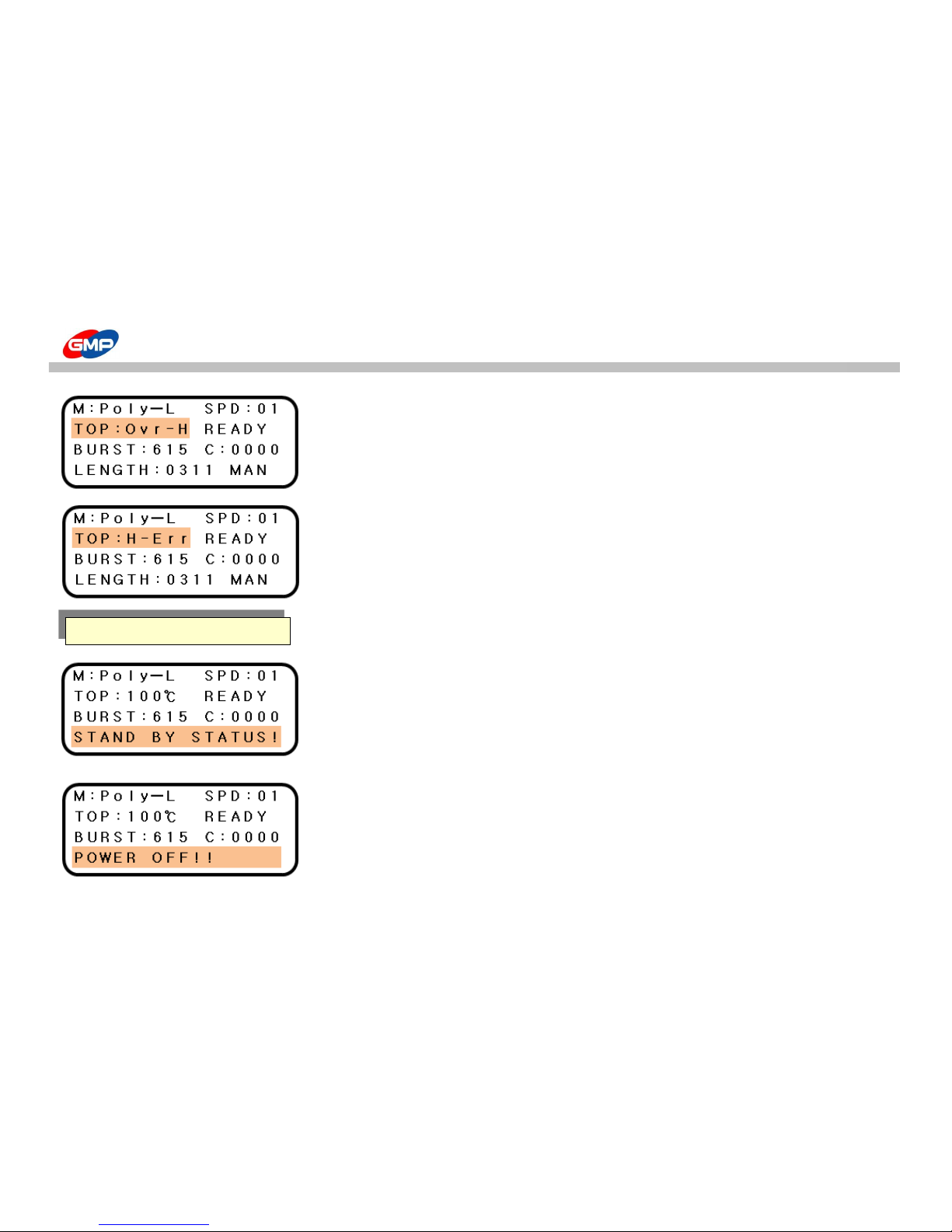
☞ "Ovr-H"
This message is displayed when the Laminating Roller temp. is higher than 170℃.
This is caused by trouble in Heater Controller.
Contact to a supplier.
☞ "H-Err"
If laminating roller temp. is fluctuated by 25℃ in 0.5 sec., the message is displayed.
This is caused by trouble in temp. sensor.
Contact to a supplier.
☞ "STAND BY STATUS!!"
This message means the machine is in STAND BY mode.
Upper Roller set temp. is higher than 80℃ in system stop status,
STAND BY time system starts. after 2 hrs from it, the machine is in STAND BY MODE.
In this status, STAND BY STATUS message is blinking on LCD panel.
To release from STAND BY MODE, press RUN button in STAND BY mode.
☞ "POWER OFF!!"
This message means the machine is in POWER OFF mode.
1 hours after STAND BY mode, POWER OFF mode starts in the machine.
In the POWER OFF mode, LCD BACKLIGHT is off and this light will be on again for back to normal.
To release from POWER OFF MODE, press RUN button in POWER OFF mode.
POWER SAVE Status
21/48
Page 22
MAIN DEVICES
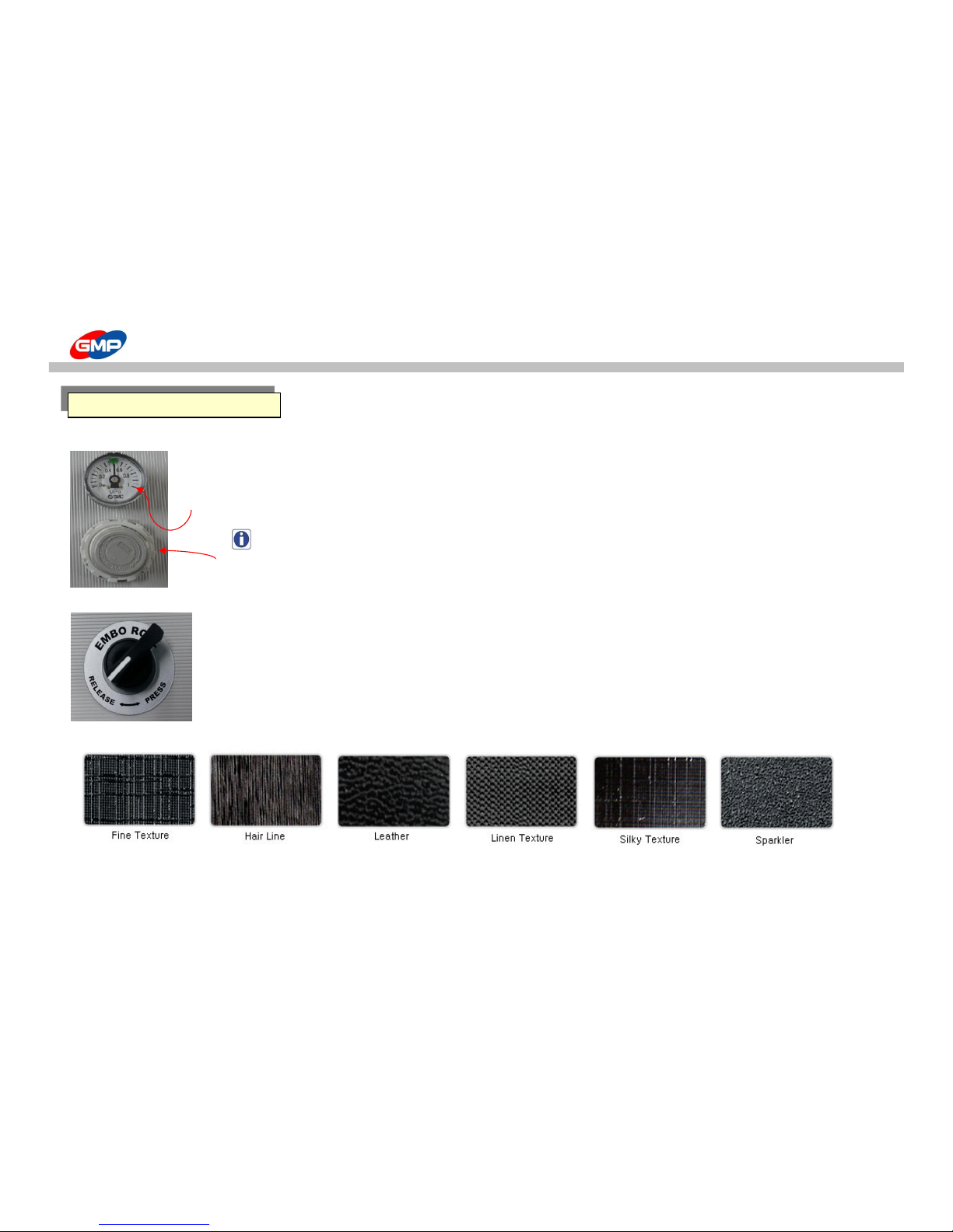
☞ Pressure Adjustment Device
Pressure on Laminating Roller & Pull Roller (for DUAL - Embossing Roller) can be adjusted by Pressure Controller and
its pressure on rollers are displayed on the gauge.
Pull the Pressure Controller to adjust the pressure. Turn it to the right to increase its pressure,
and turn it to the left to decrease the pressure. After the adjustment is done, press the controller to fix the adjustment.
NOTE : Different film or different substrate requires different pressure.
The recommendable max. pressure is less than 0.6MPa(6㎏/㎠).
☞ Switch to engage the Embossing Roller [PROTOPIC III-540DUAL]
To engage or disengage the Embossing Roller for its lamination.
Turn it to "PRESS" to engage the Embossing Roller and Embossing Laminating is started.
Turn it to "RELEASE" to disengage the Embossing Roller.
☞ EMBOSSING PATTERNS [Optional]
Different Patterned Embossing Roller makes various embossing effect on products.
This embossing lamination makes "added-value" effect on the products.
LAMINATION DEVICE
Pressure
Gauge
Pressure Controller
22/48
Page 23
MAIN DEVICES
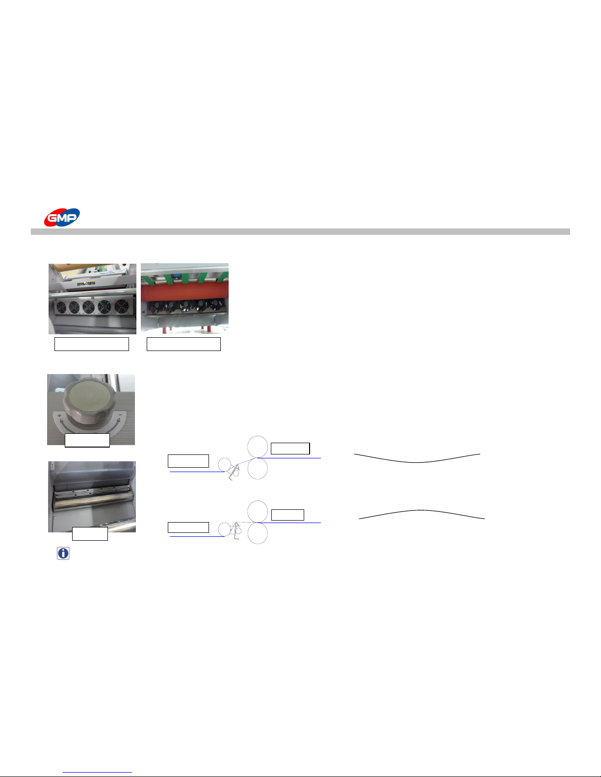
☞ Cooling Device for Embossing Roller [PROTOPIC III-540 DUAL PHOTO]
To keep the temp. on Photo Embossing Roller stable with cooling
for continuous quality of photo embossing during the job.
If photo embossing roller temp. would be higher than 35℃ , the cooler is automatically operated.
The lower cooling device is operated automatically while machine is operated
☞ Decurler
It is natural thing to have the curled laminated results after lamination.
This is not caused by the trouble in the Laminator.
Decurling Device is to avoid the Curling on the Laminated Results after single side lamination.
Adjust the Decurling Status with the Handle as the Pictures.
Rotate the Handle to the Right to increase the Decurling Value and rotate it to the left to decrease it.
Curling Way for Left Direction Rotating of Handle
Curling Way for Right Direction Rotating of Handle
NOTE : Adjust the Decurler Angle for Substrates Thickness and its Materials.
Decurler
Decurler Knob
Pull Roller
Pull Roller
Decurler
Decurler
Upper Cooling Device Lower Cooling Device
23/48
Page 24
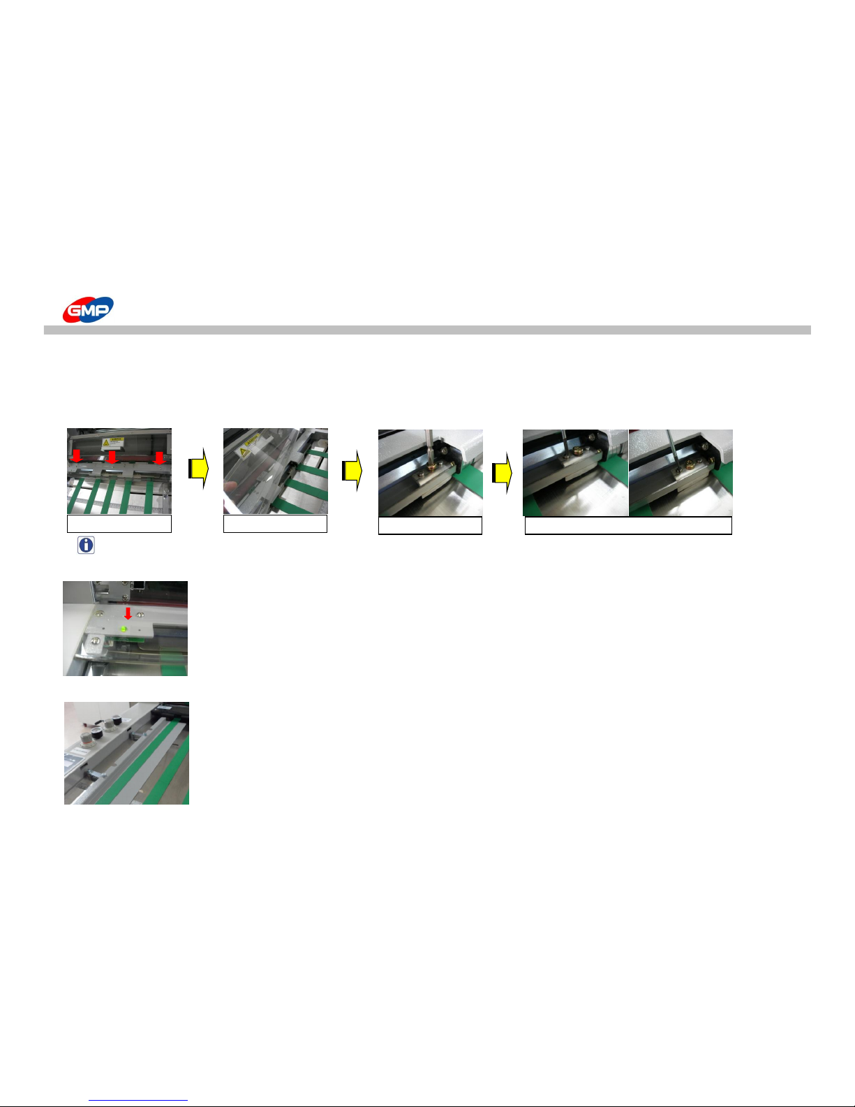
MAIN DEVICES
☞ How to adjust pressure on Feeder
Thickness / Surface Status of substrate requires adjustment on Feeder Stopper Shutter.
Different pressure on shutter could be a cause of twisted paper fed, miss feeding, etc. for error in feeding.
Bellows are the way for pressure adjustment.
NOTE : After the pressure adjustment is done, process test lamination to find a suitable pressure.
☞ Feeding Lamp
To let operator know the time to put a substrate on feeder.
When the lamp is ON, put a substrate on the feeder table. Feeder makes distance of substrates automatically.
With the transparent cover, feeding status and shutter height can be checked.
"LAMP ON" : Feeder is operated. Substrates on Feeder is fed.
"LAMP OFF" : Feeder is stopped. Substrates are on Feeder Table for feeding.
☞ Paper Guide
To feed substrate straight and it can be adjusted for substrate width.
After the position is arranged, fix it with fixing knobs.
For exact feeding, paper alignment is important factor.
1. Remove Cover Bolts
2. Remove Cover
3. Remove Fixing Bolt
4. Adjust height of pressure adjustment bolt
24/48
Page 25
MAIN DEVICES
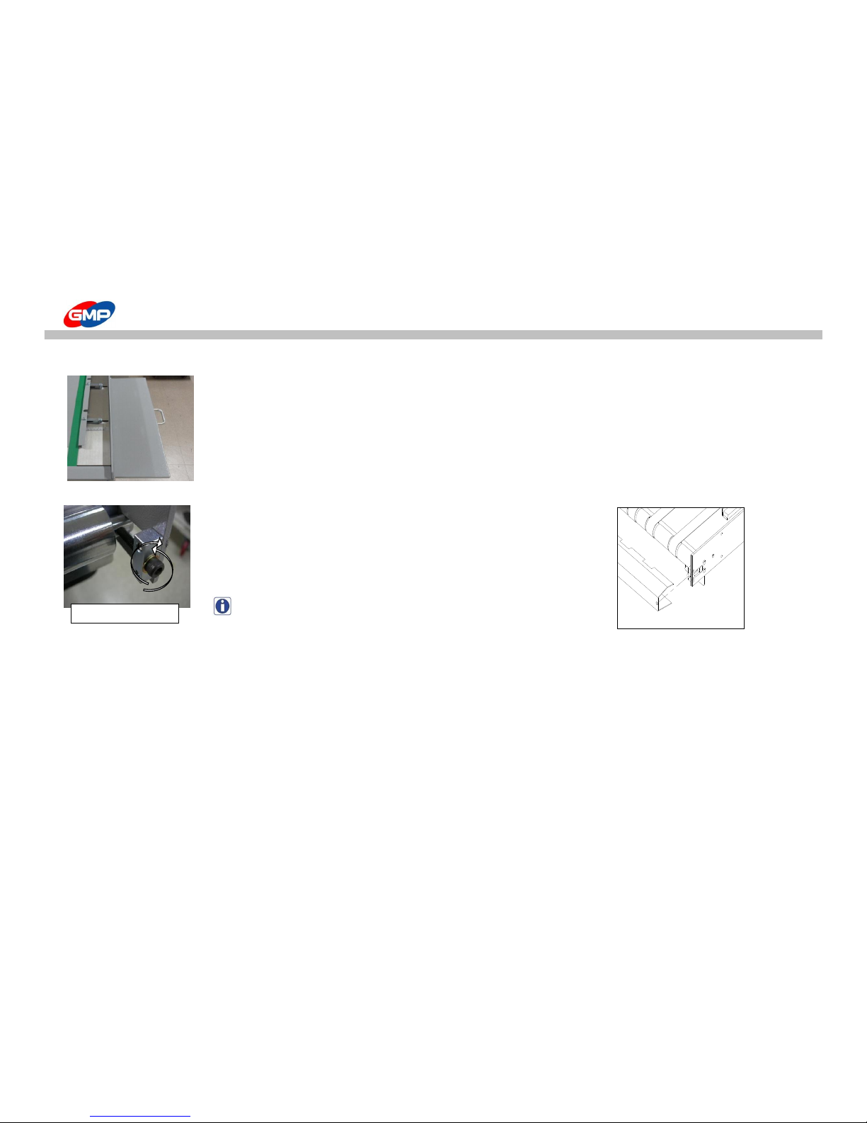
☞ Paper Table
For convenient lamination job. Substrates can be put on the table.
Pull the table handle to draw the table out.
☞ Tension Adjustment of Conveyor Belt
Long time operation could make conveyor belt loosen.
If the belt is loosen, feeding could not be working properly.
Adjust its tension with Tension Adjustment Bolts that are at Feed Table.
Turn it to the right to increase tension and turn it to the left to decrease it.
(Adjust it with 5mm Wrench that is packed in the machine.)
NOTE : Cover has to be removed to adjust it.
Tension Adjustment Bolt
25/48
Page 26
MAIN DEVICES
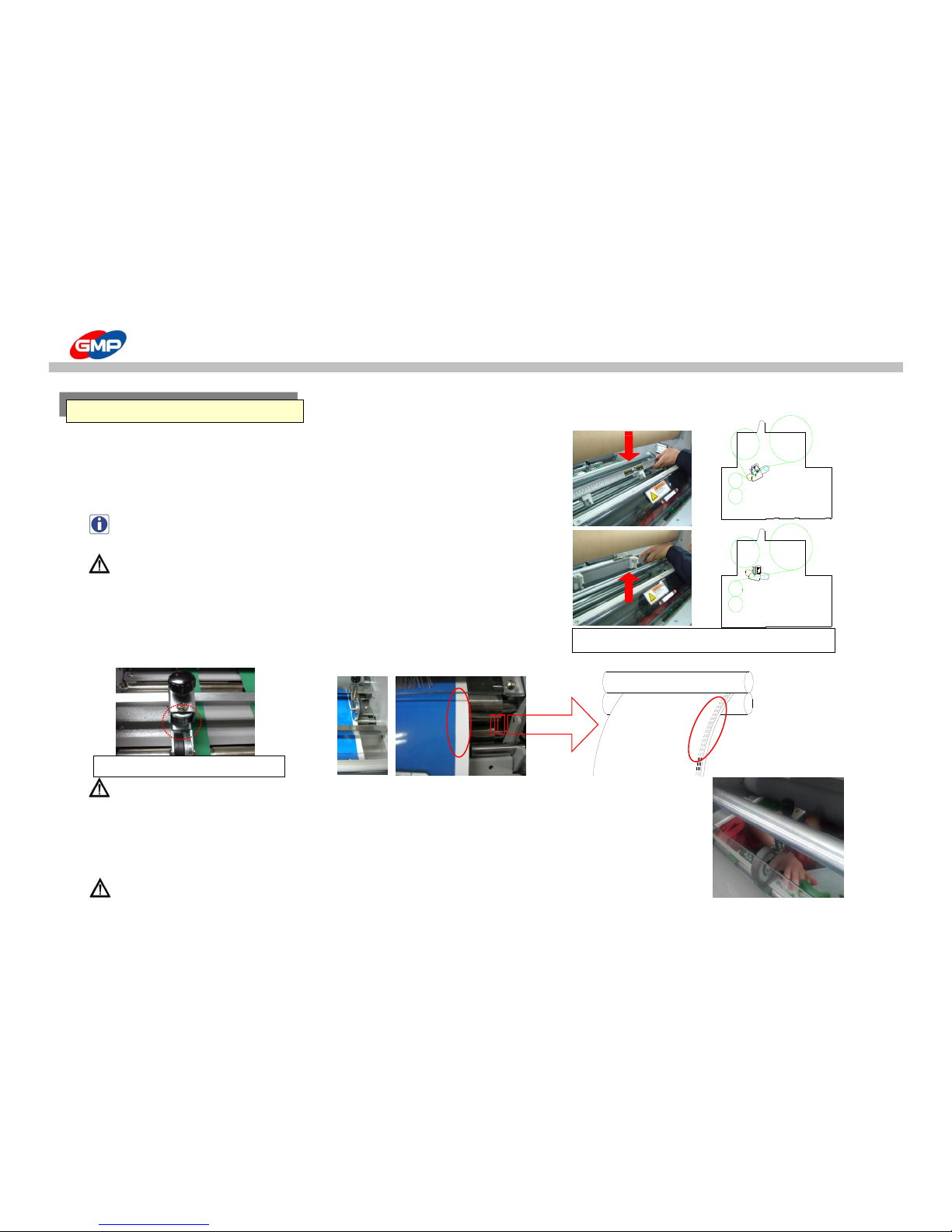
☞ Side Slitter & Rewinder
To slit film ends if a film roll width is wider than substrate.
Put the side slitters at a proper position to slit film.
Rewind the slitted films on Rewinder.
NOTE: This device is designed to be moved up/downwards for feeding.
[PROTOPIC III-540]
WARNING : Be careful to use this because sharp blade could be a cause of injury.
☞ Perforator
To cut a laminated results easily, perforator makes holes on film ends.
Position the device from the film ends by 1~3mm inside.
To make clear holes on films with adjust perforator Pressure adjustment bolt.
WARNING : In the initial loading status, if the perforator is needed to be moved,
loosen the perforator Pressure adjustment bolt. Otherwise, blade or roller could be damaged.
☞ Skewing Wheel
To help cut the laminated results and this is used to avoid "torn film" for cutting process.
As the right picture, make the laminated results have curved line to have quality results.
WARNING : If skewing wheel is not adjusted properly, laminated result could be folded.
CUTTING DEVICE
Film
Rewinder
Slit film ends with Side Slitter & Rewinder
Perforator Pressure Adjustment
26/48
Page 27
MAIN DEVICES
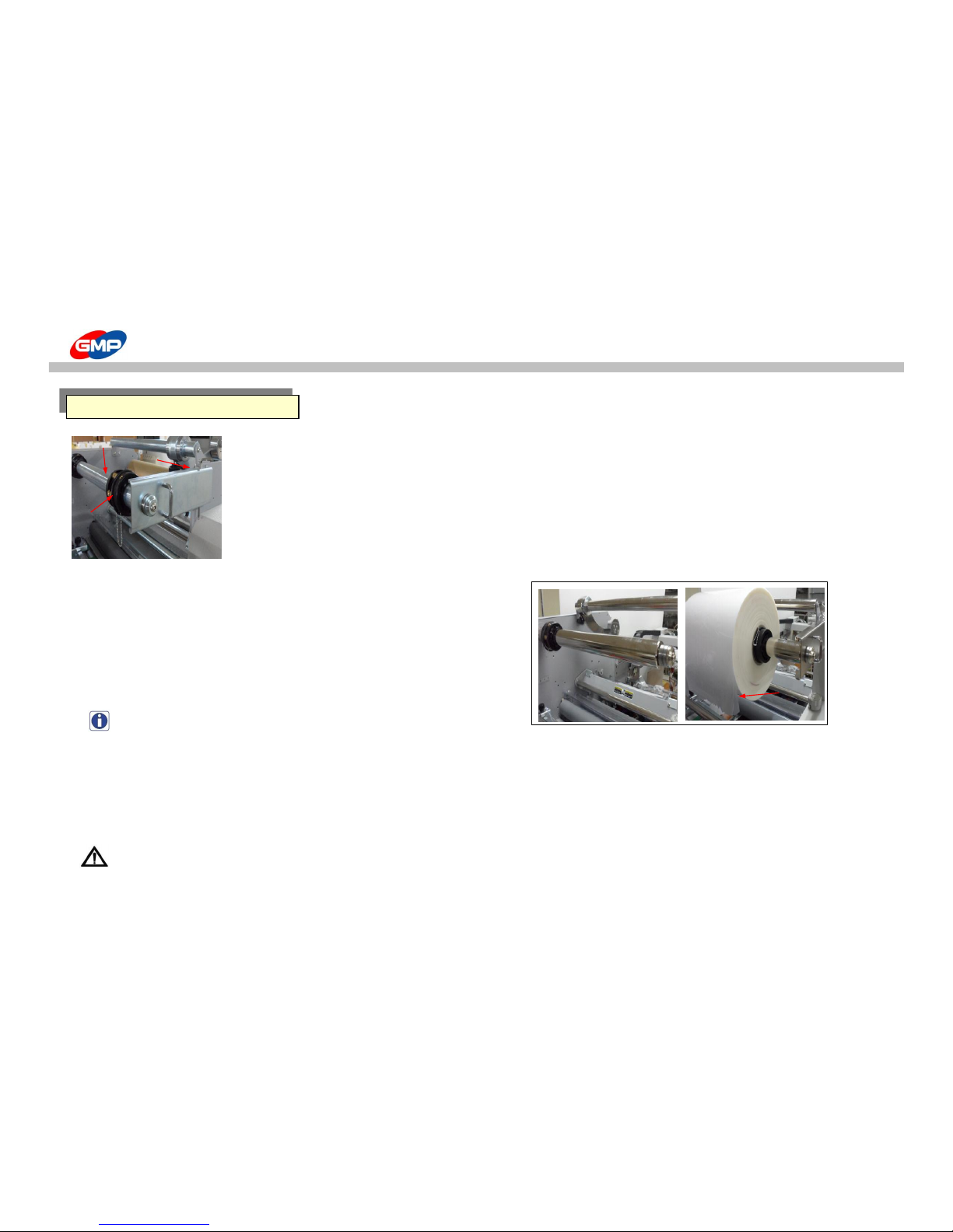
☞ Film Loading Device
1. Film Shaft : To load the Laminating Roll Film.
2. Film Shaft Holder Fixing Pin : To avoid the movement of Film Shaft Support
3. Film Shaft Holder : To fix the Film Shaft to avoid movement of Film Shaft
4. Film Core : To fix the Laminating Roll Film
※ How to load laminating film roll
1. Remove the Film Shaft Holder Fixing Pin and pull the film shaft holder.
2. Remove one of the film core adaptor with film core fixing pin.
3. Load a film roll (refer to the right picture)
4. Insert the Film Core Adaptor into film core and close the film shaft holder.
Then, place the fixing pin.
5. Place film roll at the central area of shaft and tighten up the fixing bolt.
NOTE : To avoid contamination on roller,
use film that is shorter width than substrate by 5~10mm.
☞ Film Position
In accordance with Single Side Lamination condition, the substrate width has to be wider than the film width by 5~10mm.
Otherwise, the roller can be contaminated / damaged by glue on the Film.
Position the Film at the inside of the substrate end by 3~5mm as the below picture.
WARNING : Film width has to be smaller than the substrate width by 5~10mm.
Otherwise, this could be a cause of trouble / error.
HOW TO LOAD/REPLACE FILM ROLL
②
①
③
④
①~②
③~⑤
Glue
Film
27/48
Page 28
MAIN DEVICES
☞ Main Power Switch
Power Switch is to supply or to cut the Power to the Machine.
Press the Switch to the "I" direction, the Power is ON and to the "O" direction to Power OFF.
Power Switch has Circuit Breaker to cut the power supply for overload or over current status in the machine.
NOTE : If it would be occurred for more than 2 times continuously, please ask to the supplier.
☞ Tray Table
The Tray Table is useful for easy arrangement of Laminated Results.
Adjust the Guides on the Table for Substrates' width & length.
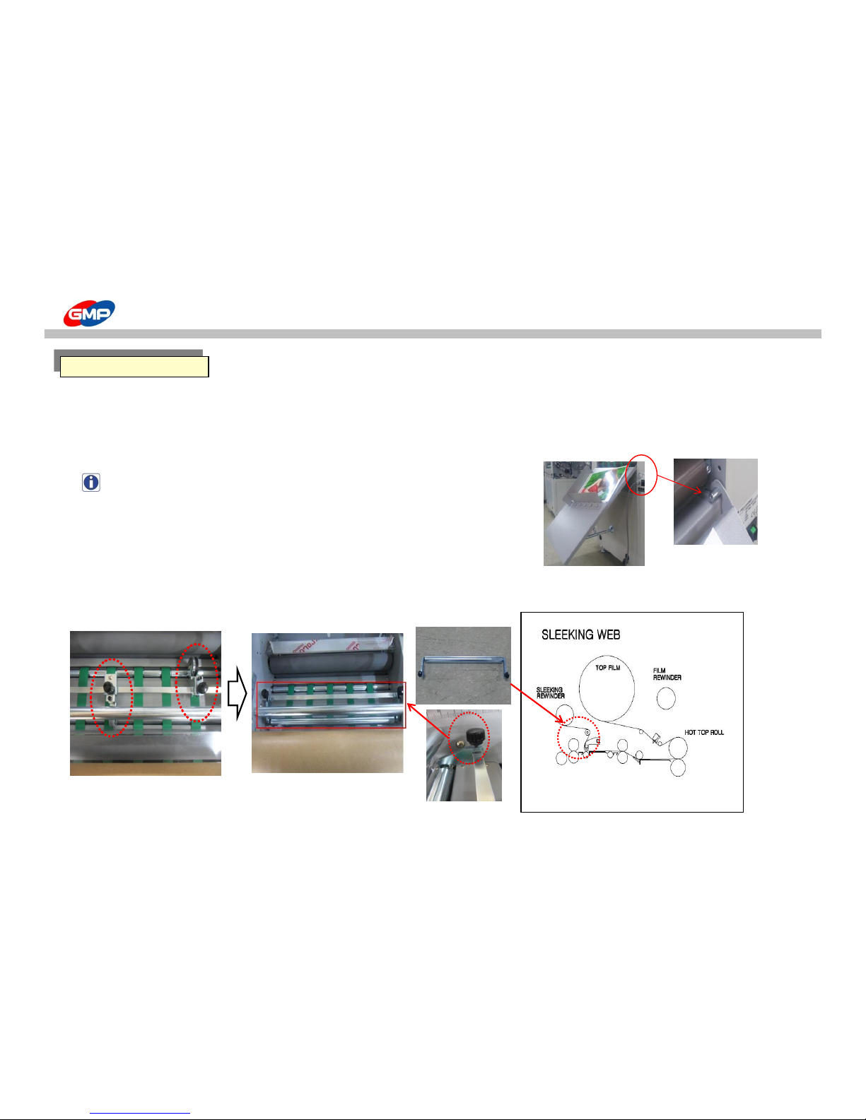
☞ Sleeking Idle Bar Installation
This is for sleeking operation to display gloss/matt, hologram, gold/silver foil in various effect.
The method of installation of Idle Bar & film for Sleeking is as below.
THE OTHER DEVICES
Sleeking Idle Bar
1. removing perforator & Skewing
Wheel
2. install idle bar for sleeking
28/48
Page 29
HOW TO LAMINATE
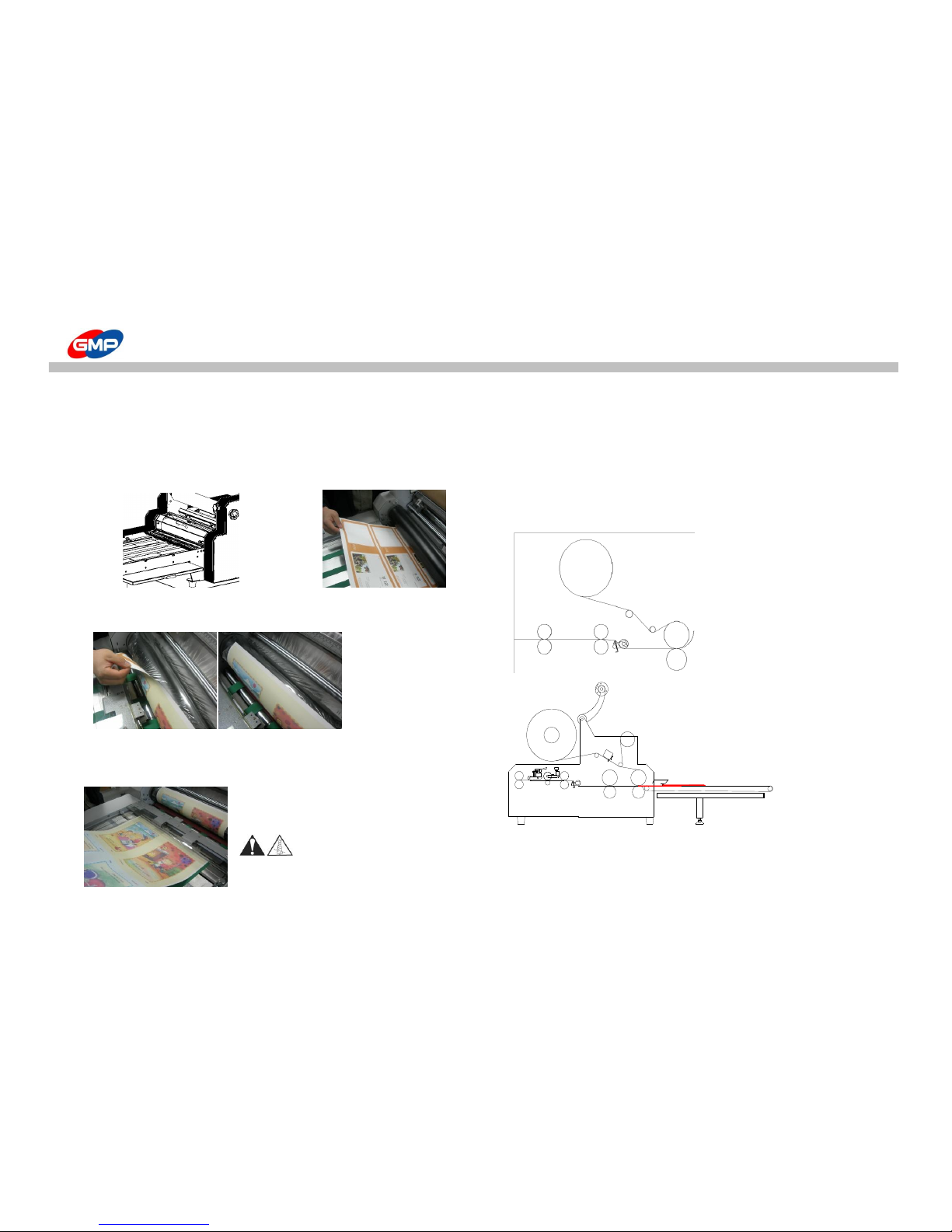
☞ Laminating Roll Film Loading for Lamination
Laminating film width has to be narrower than substrates' one by 5~10mm.
Laminating film has to be positioned inside from the substrate's edge by 5mm.
1. Remove the Roller Safety Cover. 2. Put a substrates from the laminating roller to the pull roller.
Substrate length is enough to be reached to the pull roller.
No need to use substrate for job. the important is its length.
3. Pull the Laminating film to be reached to the Laminating Roller.
When the glue is melted by roller, then attach the substrate to the film.
4. Feed substrates for job.(Roller Safety Cover has to be installed.)
Press "LOADING" button to open the Feeding Gate.
WARNING : Do not wear necktie, necklace, long-raced or that kind of clothes.
These could be wound in the driving device and will be a cause of fatal injury.
PROTOPICllI-540
PROTOPICllI-540DUAL
29/48
Page 30

HOW TO LAMINATE
☞ Test Lamination
If Roller Temp. is reached to the Setting Temp., test lamination is required to check the setting condition & lamination status.
Start at 3~5m/min speed and increase its speed.
Press "RUN" button to engage the roller and lamination is started.
※ Checking Points for Test Lamination
1. Distance of Overlap for Substrates : 3~5mm ideally
- If under lapped area is not sufficient, press "PAPER LENGTH" on control panel to adjust length of substrate.
2. Decurling Status : check the curling status of the paper and adjust it with Decurling Controller.
- Adjust its angle for substrate thickness and its material.
3. Laminating Status : Check it with various Pressure, Temp. conditions.
- Each condition requires to be adjusted for film / substrate status. The lamination quality (bonding strength) is
proportional to temp. and pressure strength and is inverse proportional to speed.
4. Cutting : Check the Bursting Roller Operation Time & Perforator status.
☞ Lamination
If the test lamination is acceptable, increase its speed for lamination.
※ Notice for Lamination
1. Stop lamination could make a mark on a laminated results.
2. Basically, thicker substrates requires lower speed or higher temp.
3. Thinner substrates requires higher speed or lower temp.
4. For perfect lamination, similar materials lamination first and adjust the conditions for real lamination.
5. If substrate would not be fed properly, this could be a cause of wrinkle.
30/48
Page 31
MAINTENANCE
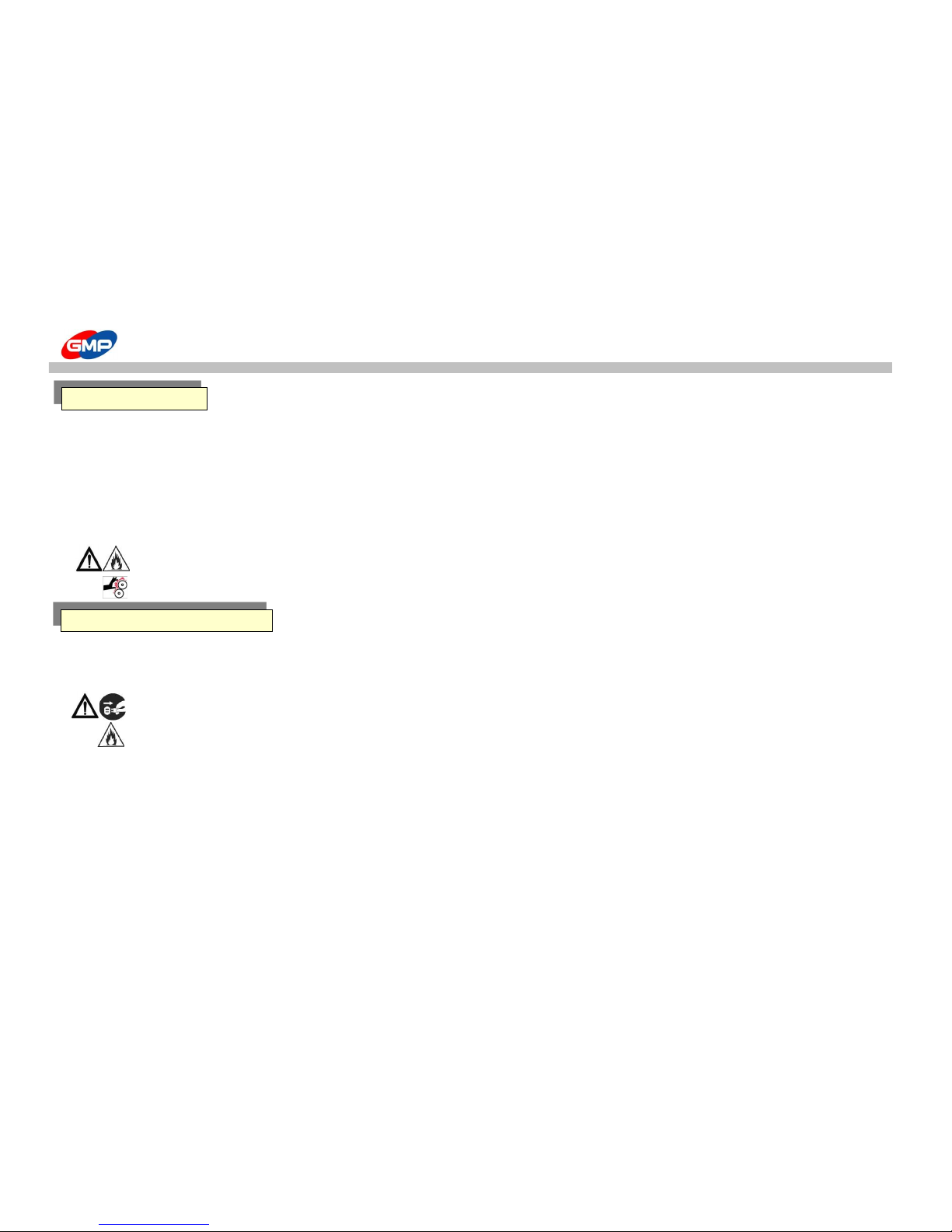
※ If the roller is not cleaned regularly,
- Film can be wound into the rollers.
- It contaminates the laminating results.
※ Roller Cleansing
- After laminating is finished, when the laminating roller temperature is below 80℃, sweep the roller with "cotton" rag and "isoprophile alcohol".
Caution : When cleansing the roller, use "isoprophilene alcohol" only.
Caution : after lamination, the laminating roller temp. is too high, if it would be contacted to body, this could be a cause of burn.
※ Main Body Cleaning
- Main body and cover should be cleansed with soft linen.
Caution : Segregate the power plug from the outlet. It can be a reason of fire flame.
Caution : Using flammable chemicals such as Acetone or Benzene can be a reason of fire flame.
ROLLER CLEANSING
MAIN BODY CLEANSING
31/48
Page 32
TROUBLE SHOOTING
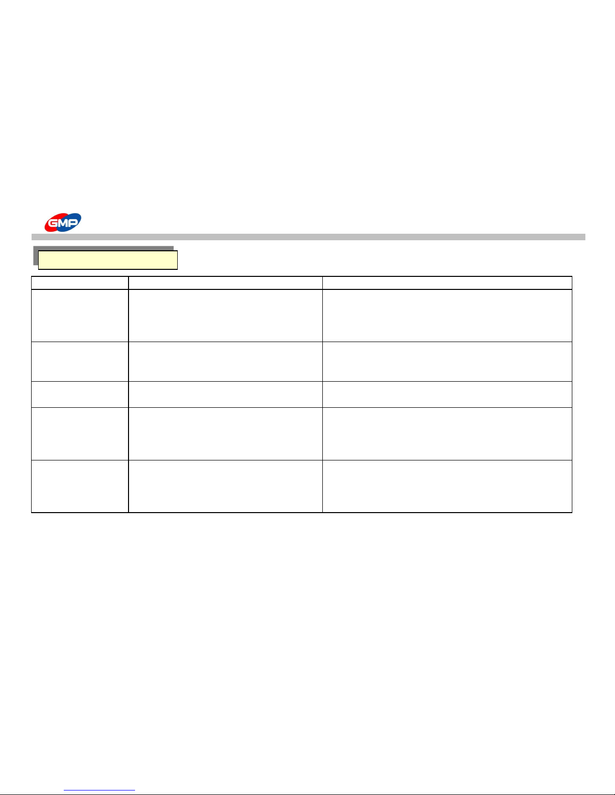
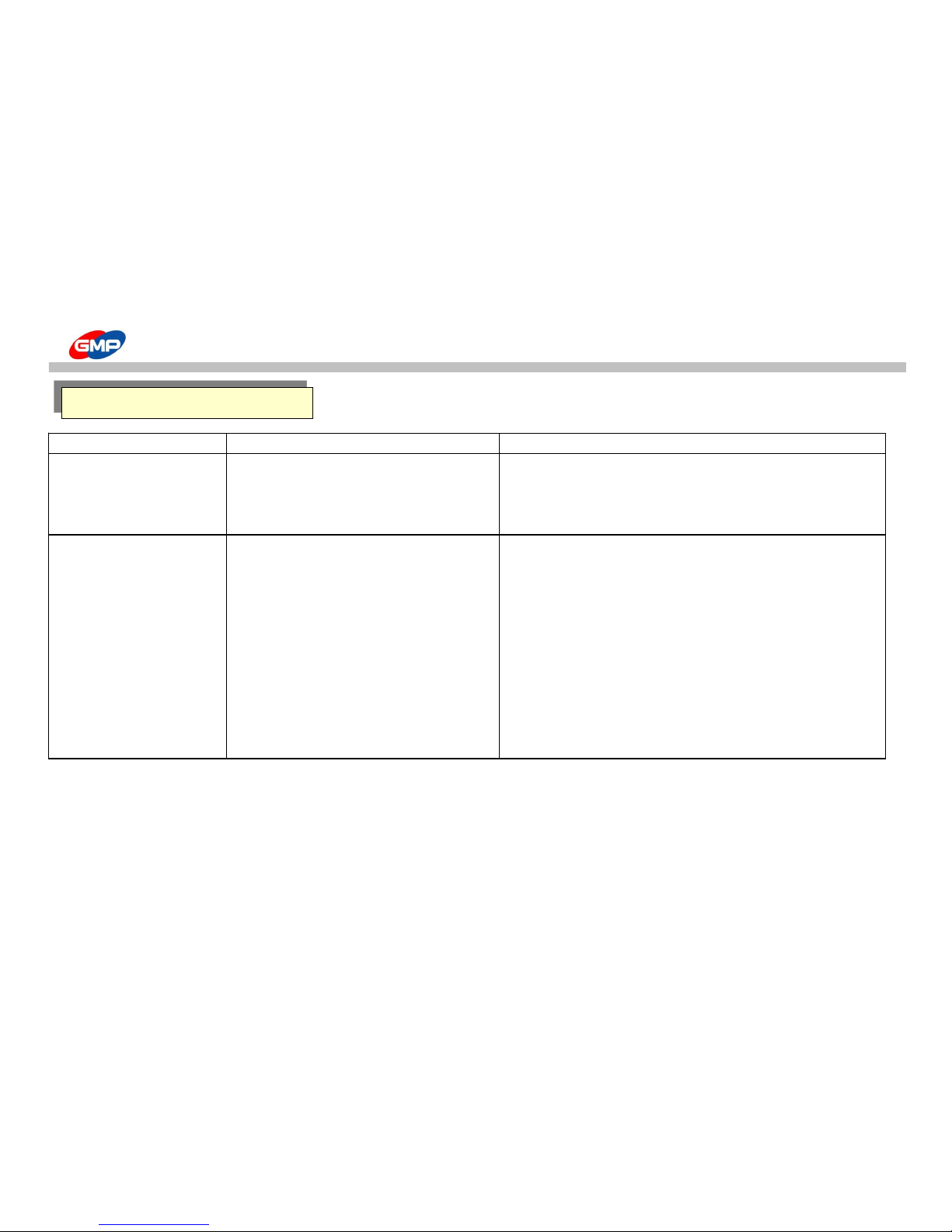
Trouble Type Reason How to solve
Laminating Roller 1. Safety Switch on the Laminating roller cover is open. 1. Close laminating roller cover safety switch.
does not work.
2. Laminating roller motor is broken OR 2. Contact our dealer or A/S center.
Timing belt is damaged.
3. Fuse disconnection 3. Exchange the enclosed fuse.
Feeding interval is irregular
1. Paper length setting is wrong.
1. Using "LENGTH" button on control panel, set the right paper length
Explanation on the function button, refer to the function button "LENGTH"
2. Irregular paper size.
2. Use the standard size paper
No feeding 1. The edge of paper conflict with the feeder 1. Spread the paper rightly and laminate
2. Paper is conveyed on only just two lines
2. Necessarily check the paper is conveyed with more than 3 lines.
Feeding paper array is not 1. Paper loading is not good on the feeding table. 1. Use paper guide
good. 2. Conveyer belt tension is not good 2. Adjust the tension using conveyer belt tension control bolt.
Refer to the laminating part "Conveyer belt tension control"
3. Paper guide status is not right
During operating, a sudden 1. Emergency switch is pressed 1. Unlock the emergency switch
stop
Refer to other device "Emergency Switch"
2. By the feeding errors, front/rear paper feeding interval
2. Using "LOADING" button, feed the new paper
is larger, system stops
Refer to each button "LOADING"
Feeding
32/48
Page 33

TROUBLE SHOOTING
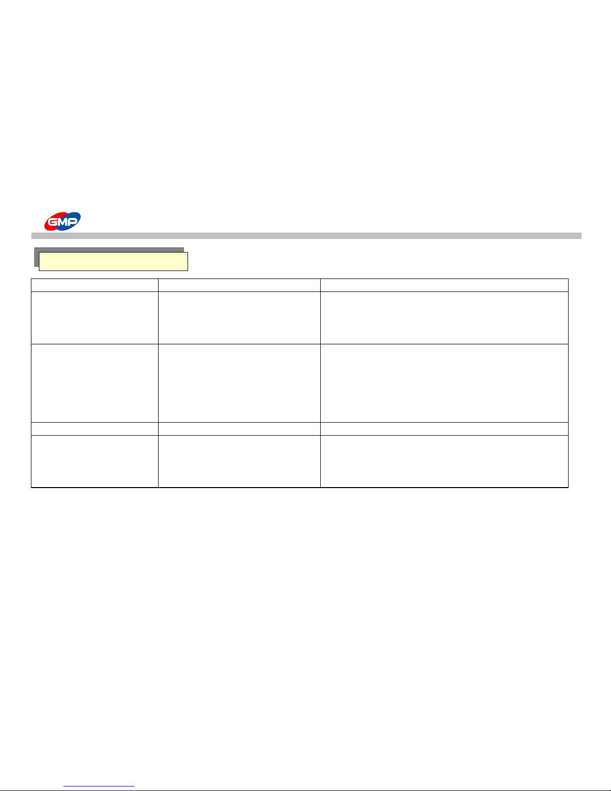
Trouble Type Reason How to solve
Laminating is not good 1. When the printing color is black
(Silvering) 2.Laminating roller pressure is not good 2. Using pressure controller, increase the pressure
Refer to Laminating "Roller Pressure control"
3. Laminating temperature is low 3. Increase the roller temperature
Decrease the roller rotating speed
4. Laminating speed is higher in not appropriate to temperature 4. Decrease roller rotating speed
Increase the roller temperature
Paper folding 1. When the paper has more humidity compared with standard or 1. Use the dried paper sufficiently
laminating using just printed materials.
2. Laminating rubber roller is broken 2. Exchange the rubber roller
Contact dealer or A/S Center
3. Laminating roller pressure is irregular 3. Contact dealer or A/S Center
4. Paper width is 30mm larger than film width 4. load the paper edge 3~5mm inside the film
Laminating results' curling
1. "Decurling" Value is lower 1. Refer to laminating part "Decurling Control"
2. Paper thickness is thin
2. Not use the paper below (80~120g/㎡)
Film sticks to the rubber roller
1. Laminating start or Paper condition change, when feeding errors
1. Insert the test paper when film loading
Film is wound into rollers.
Crease on the laminating results
1. Thin paper laminating
1. Not use the paper below.(80~120g/㎡)
2. It happens sometimes according to the paper line
3. It happens sometimes mainly due to the humidity 3. Use the sufficient dried paper
4. when the temperature is high 4. Decrease the roller temperature
Laminating
33/48
Page 34
TROUBLE SHOOTING
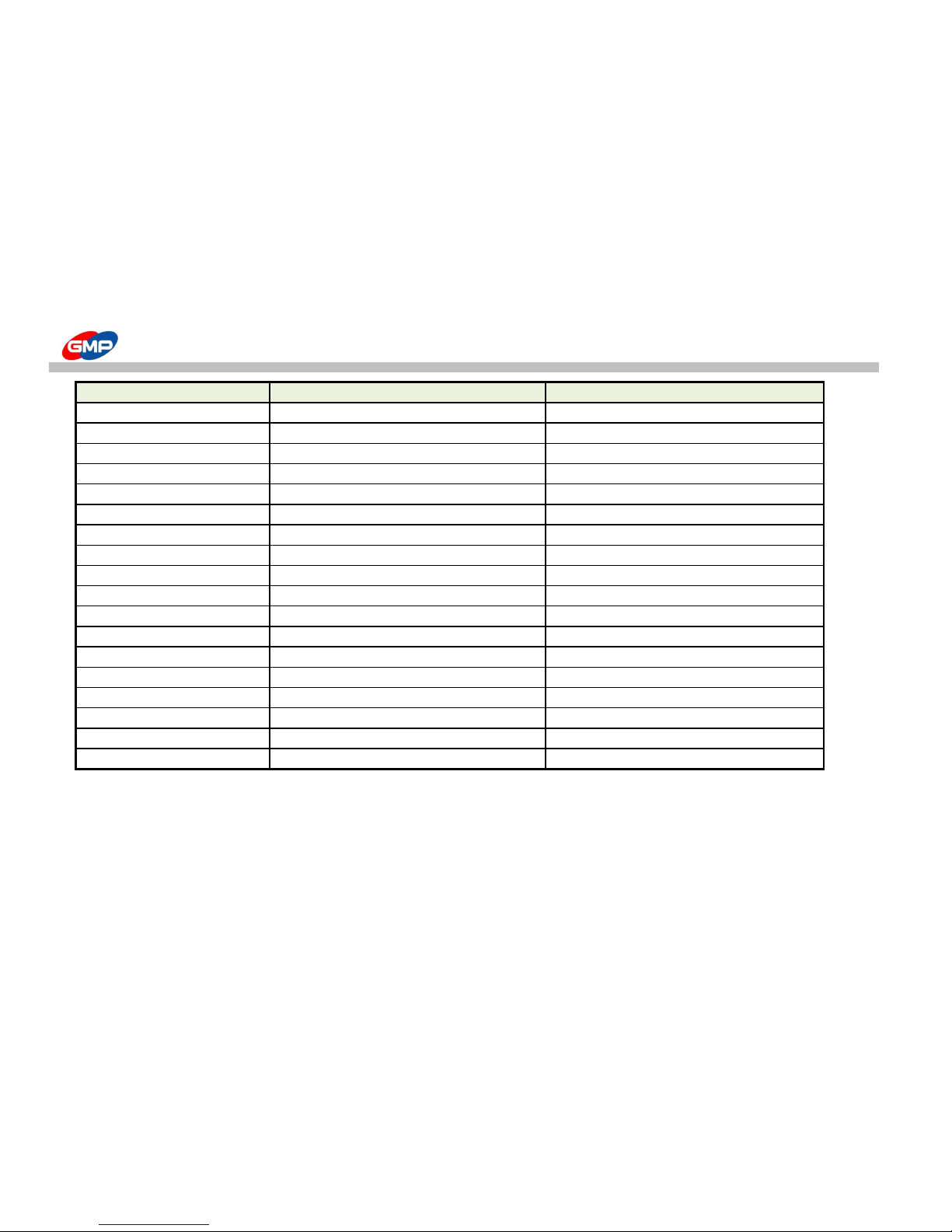
Trouble Type Reason How to solve
Cutting roller does not work
1. Cutting roller motor's disorder or
1. Contact dealer or A/S Center
Conveyer belt is broken
2. FUSE is disconnected 2. Exchange the enclosed fuse.
3. Compressor's malfunction 3 Contact dealer or A/S Center
Laminating results' cutting 1. Cutting edge of perforator is not sharp 1. Adjust the cutting edge using height control bolt
Status is not good
Refer to the Perforator "Perforator Control"
2. Cutting roller pressure is not good 2. Adjust the height of rollers using Cutting roller height control Knob
Refer to the "Cutting roller height control Knob"
3. Cutting timing is not regular
3. Timing resetting using "DISTANCE" button on control panel
Functional Adjustment refer to "DISTANCE" part
4. When not using POLYNEX(OPP) film 4. Contact dealer or A/S Center
Cutting is not good
5. In case of using NYLONEX(NYLON),
5. Using "BURST SPEED" button on control panel, rotate the cutting roller
PERFEX(PET)
at high speed.
Refer to the functional Part "BURST SPEED"
Perforating
34/48
Page 35
TROUBLE SHOOTING
Trouble Type Reason How to solve
Cutting status is not good when using 1. Rewinder tension is strong
1.Turn left the rewinder tension control knob
Rewinder
Tension decreases
2. Rewinder tension is weak 2. Turn right the rewinder tension control knob
Tension increases
Roller is not heated 1. Temperature sensor's malfunction 1. Contact dealer or A/S Center
not increase above a certain temp.
2. Odds between the temp. sensor and laminating 2. Remove odds
roller
3. Heater's disorder 3. Contact dealer or A/S Center
4. THERMOSTAT is working 4. Try again after cooling sufficiently
if same problems happens, contact dealer or A/S Center
Compressor is not working smoothly
1. Check the compressor or pressure gauge
Power is not "ON"
1. Check the Power switch is "OFF"
2. FUSE Disconnection 2. Exchange the attached fuse.
3. PCB BOX is open
3. Close "PCB BOX"
Others
35/48
Page 36
SPECIFICATION
ITEMS PROTOPIC III - 540 PROTOPIC III - 540 DUAL
Dimension(W*L*H)(mm)
800*1580*670(1340 - incl. Lami Table height) 800*1820*670(1340 - incl. Lami Table height)
Max. Laminating Speed(m/min) 15 15
Max. Paper Size(mm) 540*800 540*800
Min. Paper Size(mm) 210*203 210*203
Substrate Thickness(g/㎡) 120~350 120~350
Laminating Film
POLYNEX,PERFEX,NYLONEX FILM (20~44㎛)
POLYNEX,PERFEX,NYLONEX FILM (20~44㎛)
Rated Voltage AC 220~240V/12A
AC 220~240V/14A
Power Consumption
2.8 kw
3.45 kw
Warm-up Time
7 mins.
7 mins.
Heating System
INFRARED HEATER
INFRARED HEATER
Roller Temperature(℃)
MAX.150 MAX.150
Temp. Control JOG DIAL JOG DIAL
Speed Control JOG DIAL JOG DIAL
Bursting Motor
DC MOTOR
DC MOTOR
Roller Pressure System
Pneumatic Cylinder Pneumatic Cylinder
Film Core
77MM(3") DUAL
77MM(3") DUAL
Cooling Motor BLOWER BLOWER
Cutting System BURST CUTTING WITH PERFORATOR BURST CUTTING WITH PERFORATOR
※ External Design & Specification could be changed without any prior notice for improvement.
36/48
Page 37

DIGITAL SLEEKING SOLUTION - Introduction
GMP DIGITAL SLEEKING SOLUTION is the epoch solution to provide various value-added products with Whole Page & Spot Gloss/Matt/Hologramming
with GMP Laminators.
1. SLEEKING (GLOSS & MATT FINISH)
SLEEKING FOIL : GLOSS SLEEKING FOIL, MATT SLEEKING FOIL
2.HOLOGRAM
HOLOGRAM SLEEKING FILM
① SPARKLE-HOLOGRAM ② HIPER PLAID-HOLOGRAM ③ CRYSTAL-HOLOGRAM ④ MILKY WAY-HOLOGRAM
⑤ STAR-HOLOGRAM ⑥ SPECTRUM-HOLOGRAM
3. METALLIC SLEEKING FOIL
① GOLD ② SILVER ③ METAL-BLUE ④ METAL-GREEN ⑤ METAL-RED
4.IMAGE TRANSFER
Transfer any kind of image can be transferred to any surface with GMP Transfer Media & GMP Laminators.
DIGITAL SLEEKING SOLUTION
37/48
Page 38
SLEEKING (GLOSS & MATT FINISH)
With GMP GLOSS SLEEKING FOIL & MATT SLEEKING FOIL, the surface of Toner Based Prints / Digital Prints can be
changed for higher quality of results.
Conditions for GLOSS/MATT SLEEKING FOILS
Model
Speed Set Temp.(℃) Pressure (MPa)
Protopic-series
3 110 0.5
(Table 1.1) (Picture 1.1)
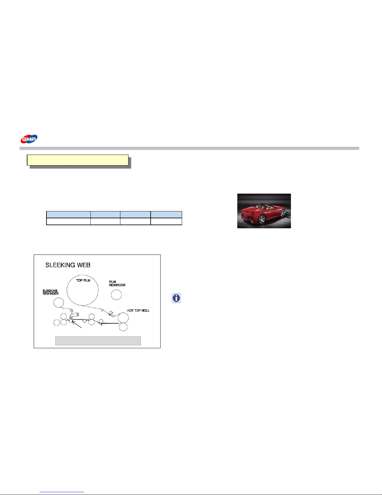
How to load the Foils
(Picture 1.2)
NOTE : To have various sleeking effect of whole page/spot/hologram, etc.,
the sleeking bar is required.
How to install the sleeking bar, please refer to the "Main Device".
1.GLOSS/MATT SLEEKING
PROTOPIC III- 540
SLEEKING IDLE BAR
38/48
Page 39

SLEEKING (GLOSS & MATT FINISH)
PRINTER FILM
Refer to the Pic. 1.2 Temp. / Speed Setting
HP INDIGO 3500 GLOSS SLEEKING FOIL
Refer to the Table 1.1
XEROX 5252
LAMINATOR
PROTOPIC 540 Series
EUROLAM 540 Series
PIONEER - 5000 FUSER
POD Prints
(DIGITAL PRINT)
FILM & LAMINATOR
Film Loading
SLEEKING
FINISH
2. Whole Page Gloss / Matt SLEEKING SOLUTION
1.Print Out POD Prints.
2.Load GLOSS/MATT
SLEEKING FOIL
* Refer to the Picture1.2
(How to load the Foils)
3.Setting
- Roller Temp. :110℃
- Speed:2
4. Put substrates on the
Feeder Table and Press
"RUN".
5.Whole surface
has Gloss Finish.
(Table.1.2) Whole Page Gloss/Matt Sleeking
39/48
Page 40
SLEEKING (GLOSS & MATT FINISH)
PRINTER
Temp. / Speed Setting
HP INDIGO 3500
Refer to the Table 1.1
XEROX 5252
POD Prints
(DIGITAL PRINT)
POD Prints
(DIGITAL PRINT)
SLEEKING
FINISH
OFFSET Prints
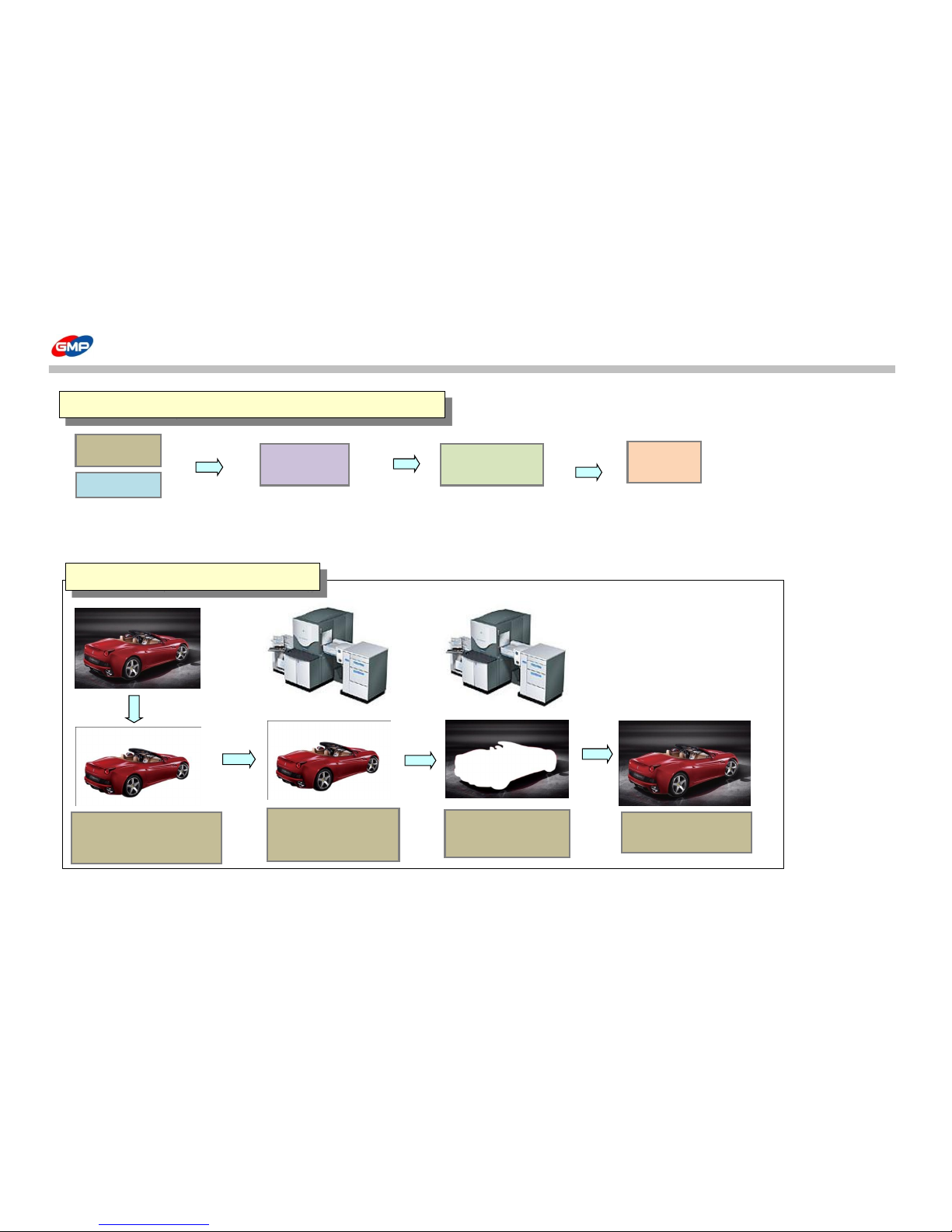
1.Cut the Car
Image(Picture 1.2) with
Image Editing Program
3. Print the
Background Image.
4. Only the Spot
Image has Sleeking
(Table 1.3) Spot Gloss / Matt Sleeking
3. Spot Gloss/Matt SLEEKING SOLUTION with Prints
2. Print the Spot Image
only and Sleeking
40/48
Page 41
SLEEKING (GLOSS & MATT FINISH)
PRINTER LAMINATOR
Refer to the Table 1.1
HP INDIGO 3500
PROTOPIC 540 Series
XEROX 5252
EUROLAM 540 Series
PIONEER - 5000 FUSER
POD Prints
(DIGITAL PRINT)
LAMINATING
POD Prints
(DIGITAL PRINT)
SLEEKING
FINISH
OFFSET Prints
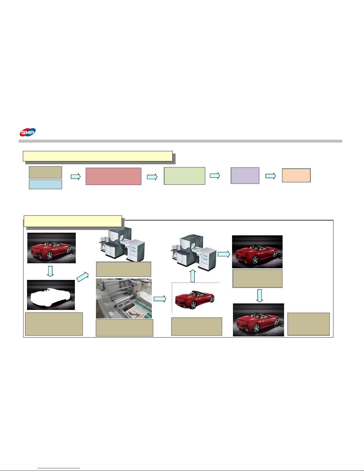
1.Cut the Car Image(Picture
1.2) with Image Editing
Program
2. Print out the Background
Image only.
3. Laminate in GMP
Laminator with GMP
Sleeking Foil.
4. Print the Spot Image
on the Laminated Surface.
5. Sleeking on the
Printed Surface in
process of (Table 1.2)
6. Only the Spot
Image has Sleeking
Effect.
(Table1.4) Spot Gloss / Matt Sleeking
4. Spot Gloss / Matt SLEEKING SOLUTION with Lamination
41/48
Page 42
SLEEKING(HOLOGRAM FINISH)
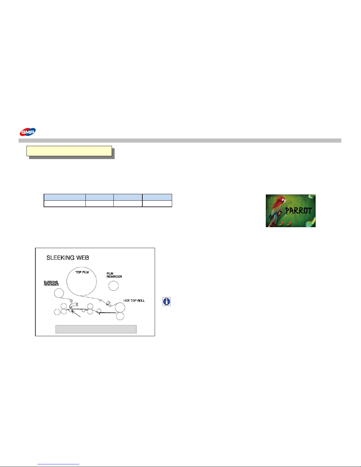
With GMP Hologram SLEEKING FOIL, the surface of Toner Based Prints / Digital Prints can be changed for higher quality of results.
Conditions for HOLOGRAM SLEEKING FOIL HOLOGRAM SLEEKING FOILS
Model
Speed Set Temp.(℃) Pressure (MPa)
① SPARKLE-HOLOGRAM
PROTOPIC II Series
3 105 0.5
② HIPER PLAID-HOLOGRAM
③ CRYSTAL-HOLOGRAM
(Table 2.1)
④ MILKY WAY-HOLOGRAM
⑤ STAR-HOLOGRAM
⑥ SPECTRUM-HOLOGRAM
⑦ MOSAIC-HOLOGRAM (Picture 2.1)
How to load the Foils
(Picture 2.2)
NOTE : To have various sleeking effect of whole page/spot/hologram, etc.,
the sleeking bar is required.
How to install the sleeking bar, please refer to the "Main Device".
1.HOLOGRAM SLEEKING
PROTOPIC III- 540
SLEEKING IDLE BAR
42/48
Page 43
SLEEKING(HOLOGRAM FINISH)
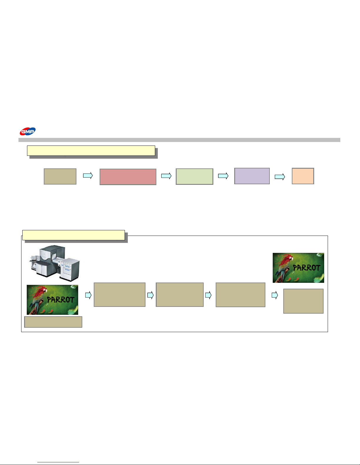
① Whole Page Hologram Sleeking
PRINTER FILM
Refer to the Picture 2.1 Temp. / Speed Setting
HP INDIGO 3500 HOLOGRAM SLEEKING FOIL
Refer to the Table 2.1
XEROX 5252
LAMINATOR
PROTOPIC 540 Series
EUROLAM 540 Series
PIONEER - 5000 FUSER
POD Prints
(DIGITAL PRINT)
FILM & LAMINATOR
Foil Loading
SLEEKING
FINISH
2. Whole Page HOLOGRAM SLEEKING SOLUTION
1.Print Out POD Prints.
2.Load Hologram
Sleeking Foil
* Refer to the Picture1.2
3.Setting
- Roller Temp. :105℃
- Speed:2
4. Put substrates on the
Feeder Table and Press
"RUN".
5.Hologram
Sleeking Effect on
the Whole Page.
(Table.1.2) Whole Page Hologram Sleeking
43/48
Page 44
SLEEKING(HOLOGRAM FINISH)
PRINTER
Temp. / Speed Setting
HP INDIGO 3500
Refer to the Table 2.1
XEROX 5252
POD Prints
(DIGITAL PRINT)
POD Prints
SLEEKING
FINISH
OFFSET Prints
2. Spot HOLOGRAM SLEEKING SOLUTION
(Table.2.3) Spot Hologram Sleeking
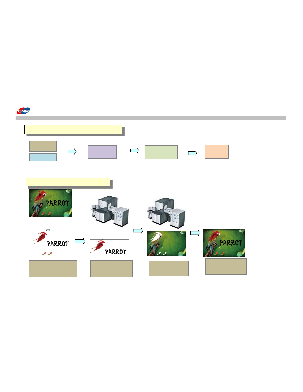
1.Cut the Carrot
Image(Picture 2.1) with
Image Editing Program
3. Print the
Background Image.
6. Only the Spot
Image has Hologram
Sleeking Effect.
2. Print the Spot Image
only and Sleeking
44/48
Page 45
SLEEKING(HOLOGRAM FINISH)
PRINTER LAMINATOR
Refer to the Table 2.1
HP INDIGO 3500
PROTOPIC 540 Series
XEROX 5252
EUROLAM 540 Series
PIONEER - 5000 FUSER
POD Prints
(DIGITAL PRINT)
LAMINATING
POD Prints
(DIGITAL PRINT)
SLEEKING
FINISH
OFFSET Prints
3.Spot HOLOGRAM SLEEKING SOLUTION - with Lamination
(Table.2.4) Spot Hologram Sleeking - with Lamination
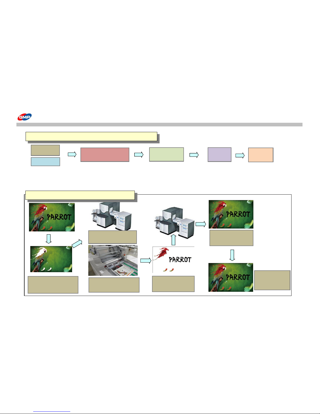
1.Cut the Carrot
Image(Picture 2.1) with
Image Editing Program
2. Print out the Background
Image only.
3. Laminate in GMP
Laminator with GMP Sleeking
Foil.
4. Print the Spot Image
on the Laminated
Surface.
5. Sleeking on the
Printed Surface in
process of (Table 2.2) d
6. Only the Spot
Image has Sleeking
Effect.
45/48
Page 46
METALLIC SLEEKING
GMP METALLIC SLEEKING FOIL makes different effect on the printed area for highlight.
Conditions for METALLIC SLEEKING FOIL METALLIC SLEEKING FOIL
① GOLD
Model
Speed Set Temp.(℃) Pressure (MPa)
② SILVER
PROTOPIC II Series
3 110 0.5
(Table 3.1)
How to load the Foils (Picture 3.1)
(Picture 3.2)
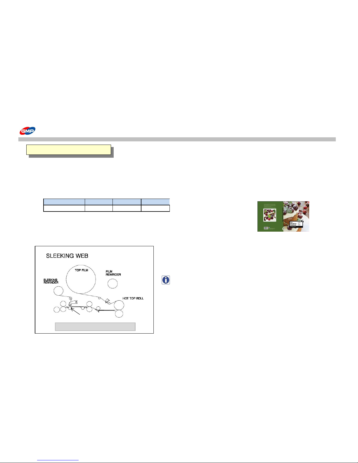
NOTE : To have various sleeking effect of whole page/spot/hologram, etc.,
the sleeking bar is required.
How to install the sleeking bar, please refer to the "Main Device".
1.SPOT METALLIC SLEEKING
PROTOPIC III- 540
SLEEKING IDLE BAR
46/48
Page 47

METALLIC SLEEKING
PRINTER
Temp. / Speed Setting
HP INDIGO 3500
Refer to the Table 3.1
XEROX 5252
(Table.3.3) Spot Gold/Silver Metallic Sleeking
2. Spot METALLIC SLEEKING
POD Prints
(DIGITAL PRINT)
POD Prints
(DIGITAL PRINT)
SLEEKING
FINISH
OFFSET Prints
5.Only Spot Image has the Sleeking Effect.
1.Cut the Spot
Image(Picture 3.1) with
Image Editing Program
2. Print out the Spot Image
only.
3. Laminate in GMP
Laminator with GMP
Sleeking Foil.
4. Print the Background Image.
47/48
Page 48
SLEEKING FOIL SPECIFICATION
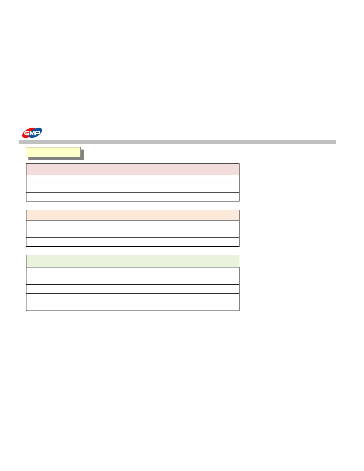
MEATALLIC FOIL (GOLD,SILVER)
SINGLE COLOR FOIL
3000M
MULTI COLOR FOIL 3000M
HOLOGRAM FOIL 3000M
SLEEKING FOIL
GLOSS 77CORE * 1000M,2000M
MATT 77CORE * 1000M,2000M
DUAL 77CORE * 1000M,2000M
HOLOGRAM SLEEKING FOIL - SPECTRUM,MILKYWAY,CRYSTAL,STAR,MOSAIC,SPARKLE,HYPER PLAID
HOLOGRAM SLEEKING FOIL-PET12 77CORE * 1000M
HOLOGRAM SLEEKING FOIL-PET25 77CORE * 1000M
HOLOGRAM SLEEKING FOIL-PET50 77CORE * 1000M
HOLOGRAM FOIL-UV20 77CORE * 1000M
HOLOGRAM FOIL-UV30 77CORE * 1000M
SLEEKING FILM
48/48
 Loading...