

Page 1
2015. 07. 29
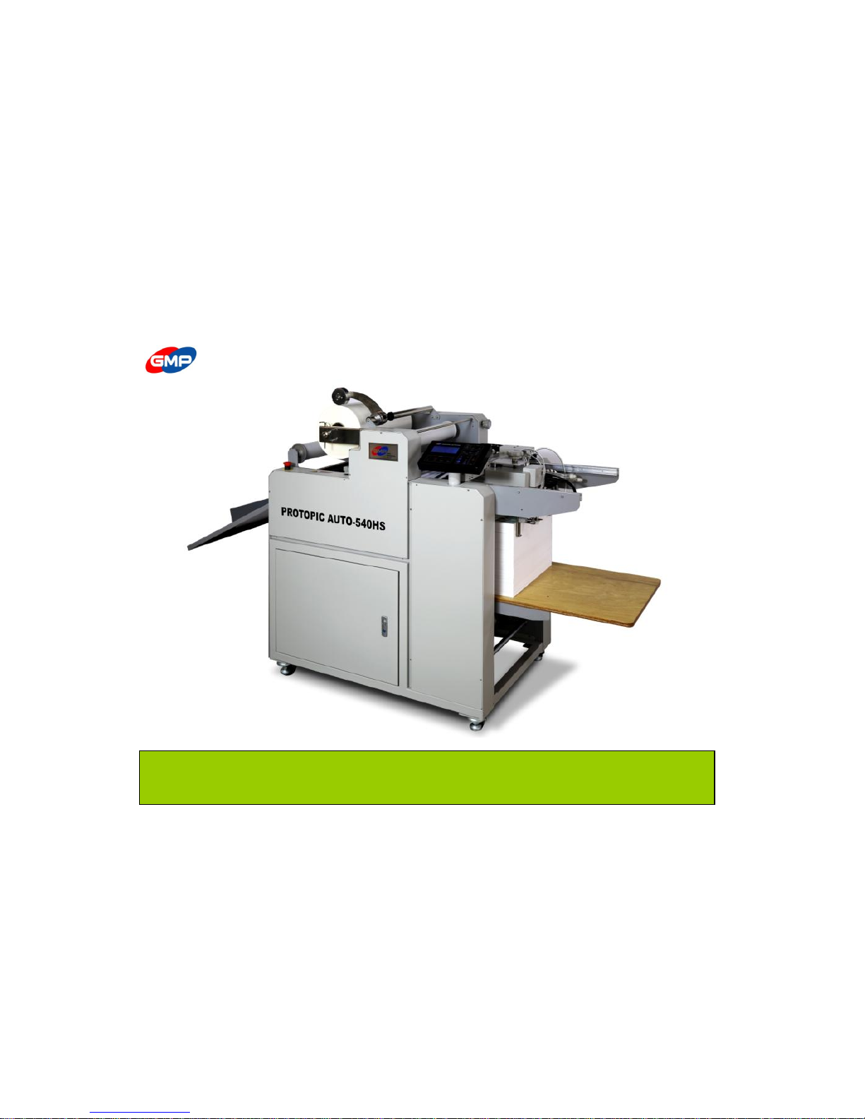
USER MANUAL FOR PROTOPIC AUTO-540 HS
Before operating the unit, please read this manual thoroughly and retain it for future reference.
The design / specification of the machine could be changed for improvement without any prior notice.
Page 2

INDEX
◐ SAFETY ◐ HOW TO LAMINATE
42 page
Important Safety Instruction
3 page
Safety Device
6 page
◐ MAINTENANCE
48 page
Warning Stickers
8 page
◐ TROUBLESHOOTING
49 page
◐ INSTALLATION
Packing Contents
10 page
◐ SPECIFICATION
54 page
Main Devices
11 page
Move & Installation
14 page
◐ DIGITAL SLEEKING SOLUTION
Introduction of DIGITAL SLEEKING SOLUTION
55 page
◐ HOW TO USE CONTROL PANEL
GLOSS & MATT SLEEKING
56 page
Details for Display
22 page
HOLOGRAM SLEEKING
60 page
Control Panel
25 page
METALLIC SLEEKING
64 page
Messages
29 page
FILM SPECIFICATION
66 page
◐ HOW TO USE MAIN DEVICES
Feeding Area
33
Lamination Area
37
Cutting Area
38 page
Film Load / Replacement
39 page
Other Devices
41 page
Page 3
Important Safety Instruction
"Important Safety Instruction " is for the purpose of user's safety
and prevention of Property loss. Read thoroughly and Use rightly according to the manual
Warning : If you ignore this symbol, you could suffer serious injury or death
Caution: If you ignore this symbol, you could receive a serious injury or loss of property
This symbol means a prohibited action. If you ignore a prohibited action, you could suffer a personal injury and damage the machine
This symbol means a required action. If you don't follow this action, your safety is not guaranteed.
Required action will be included in this symbol.
Reference: The sign above refers the contents for user's safety and prevention of Property loss.
☞ Power
Do not connect or disconnect with wet hands, as this will cause an electric shock
Do not overload a power supply, as this will cause a fire and an electric shock.
Do not use a damaged plug or lead, as this could cause a fire or an electric shock
Do not use other voltage and power supply other than specified, as this will cause a fire and an electric shock.
Make sure plug is in the socket, as it could cause fire or an electric shock
WARNING
3/66
Page 4
Important Safety Instruction
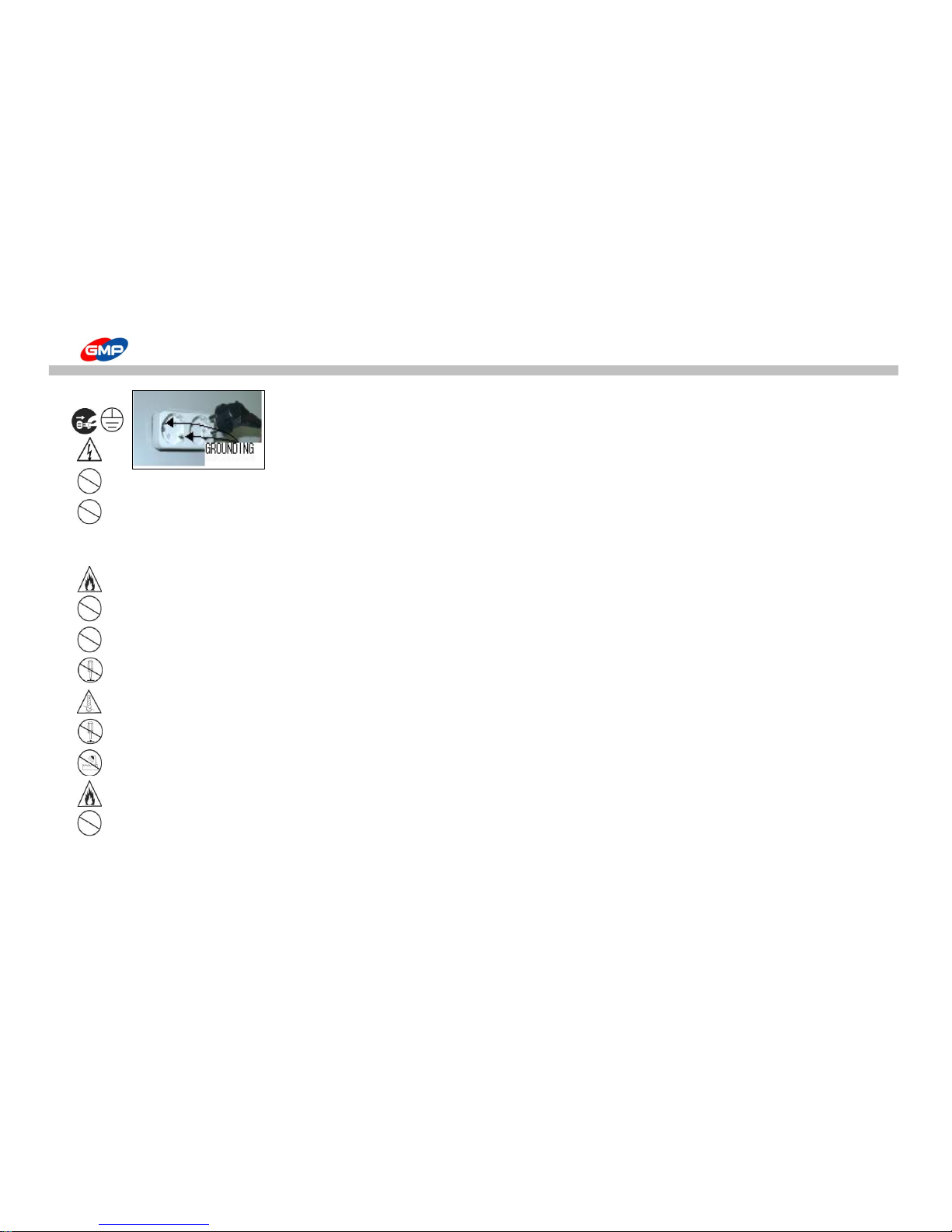
It must be grounded for safety.
Otherwise, this could be a cause of trouble and electric shock.
Danger, Malfunction, loss of electricity could cause an electric shock
Do not pull the plug or bend improperly
☞ Installation
Do not use materials near a naked flame
Do not use the machine in the sealed place.
Only use the specified power and voltage. It can be a reason of fire flame or an electricity fire flame.
Do not dissemble, make repairs or convert the machine. Contact your dealer for repairs
Ensure all hair, neckties, necklaces, are kept free of the feeding table to avoid injury
Do not convert the safety device and safety switch.
Do not spill any liquids on the laminator as this will cause damage and a possible electric shock
Do not use the flammable spray or flammable materials inside or outside the machine. As this could cause a fire.
Do not allow children use of this equipment
4/66
Page 5

Important Safety Instruction
☞ Power
When moving the product, turn off the power switch, disconnect the power plug from the socket
When laminator is not in use, you must turn off the power switch, disconnect the power plug from the socket.
☞ Installation
Danger - laminating blades are sharp and can cause injury.
More than 2 people are needed to carry this equipment to avoid personal injury or damage to the machine.
Keep gears and chains free of all materials
Do not touch the roller with your hand as you could be burnt.
Please avoid installing near the following places;
Gas stove, Ventilator or Air conditioner due the higher temperature or higher humidity
Do not place any materials on the laminator as they could catch a fire
Avoid the direct sunlight for the installing the machine
Make sure no vibration and dusts are found in the place during the installation.
Avoid the dark and slope place for installation
Do not place any materials on the laminator as they could catch a fire
Do not touch the film and laminating machine just after lamination finishes as you could be burnt.
Use the machine with laminating purpose only.
Tidy up the place near the laminating machine.
CAUTION
5/66
Page 6
Safety Device
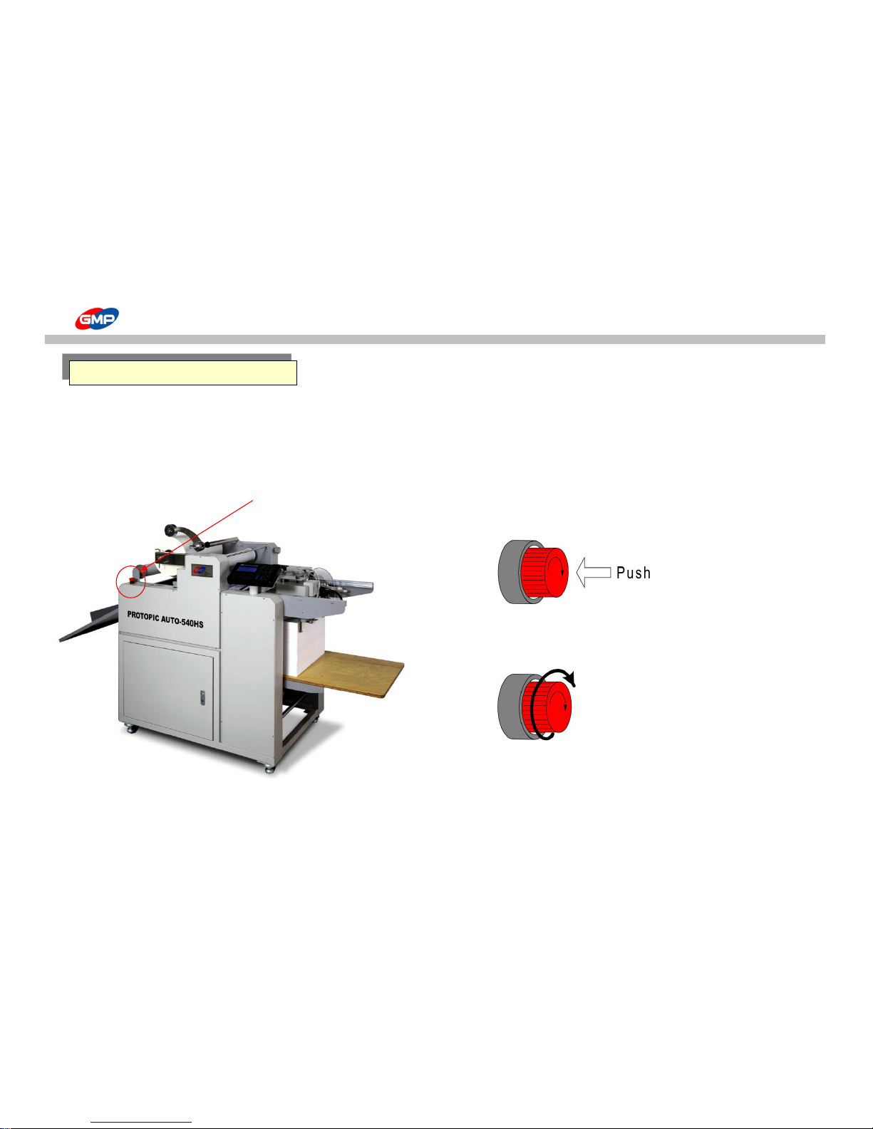
☞ Emergency Stop Switch
When emergency situation happened, it stops the running motor(rollers) rotation and system operation.
In case of emergency, use this switch.
☞ Position of E-Stop Switch ☞ How to use
Press the Red button to operate the Emergency Stop Switch.
All system is stopped when this is pressed.
Turn the switch to the right to release from Emergency Status.
Emergency Stop Switch
E-Stop S/W
6/66
Page 7
Safety Device
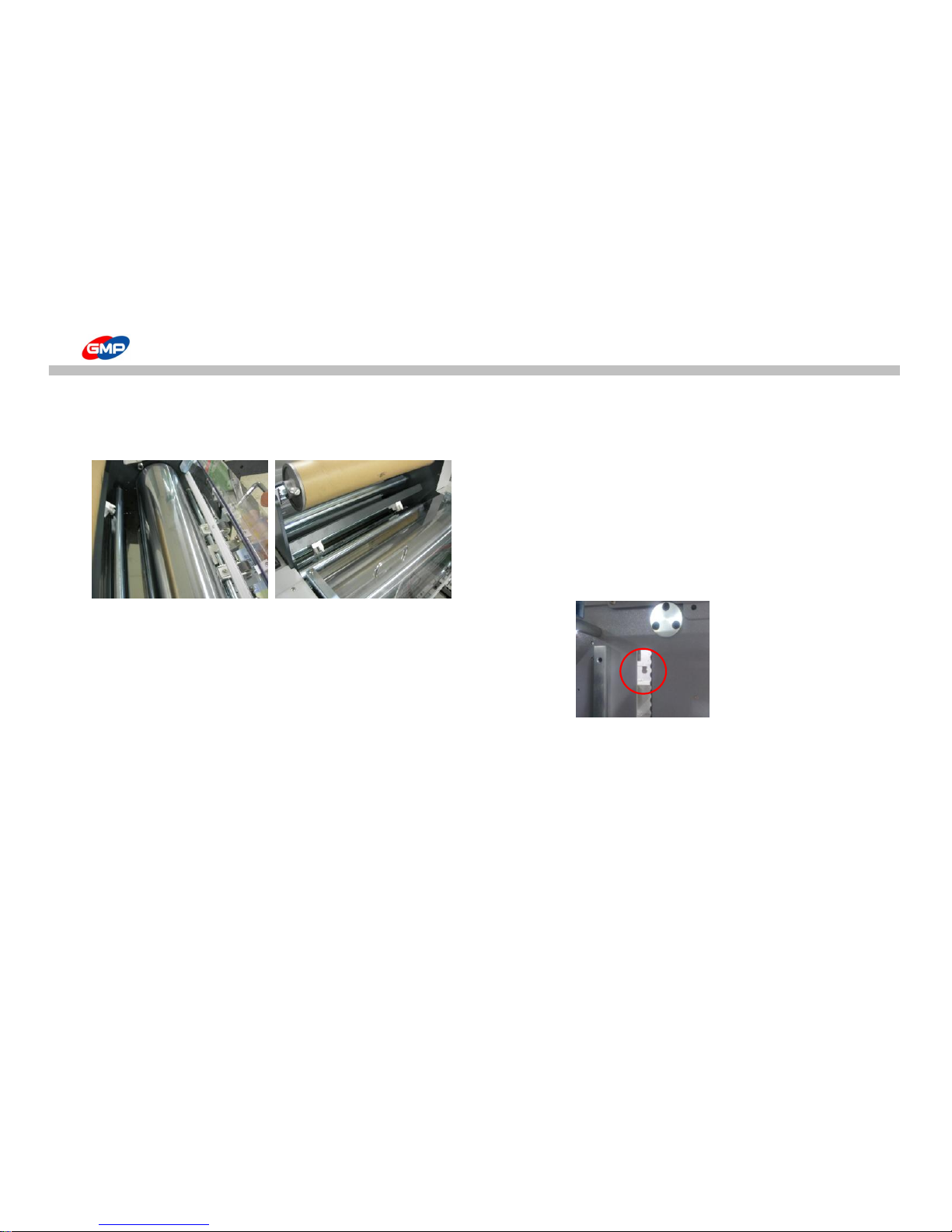
☞ Laminating Roller Safety Cover
It protects the workers from the burnings that may be occurred by touching hot roller
Make sure the Safety Cover is always closed, except when Film is being loaded.
☞ Switch for Protection of Feeding Device
It prevents the damage of feeding device from feeding table
The system is not working once the safety switch is activated
by abnormal raising of feeding table as right picture.
When the lever gets it's original position, the system will be working.
7/66
Page 8
WARNING STICKERS
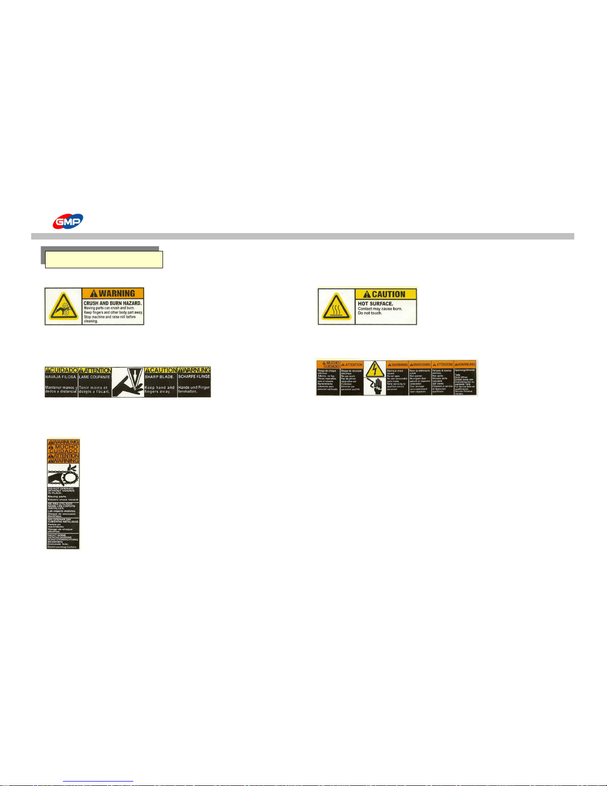
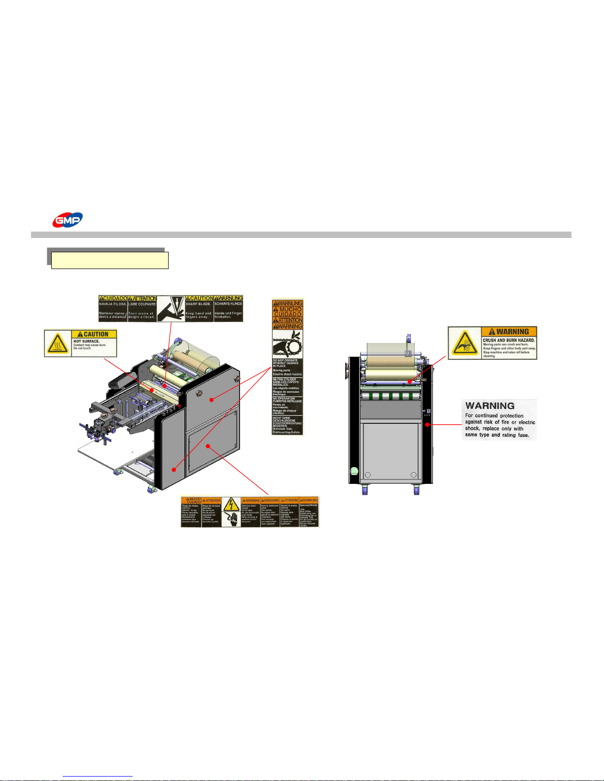
For the user safety, in the outer design, the below sticker is attached. Be cautious not to injured during operation.
☞Roller caution ☞ Higher Temperature
Do not touch the roller and heating plate with your hand as you could be burnt.
Do not touch on the heating part
Roller's higher temperature and press can damage your body
☞Cutting Caution ☞ Electricity Caution
Do not touch your body on the trimming device Inside the machine, high voltage flows,
You can suffer an injury
Do not open the outer case
You can suffer injury or sudden death with electricity shock
☞Chain Caution
Do not your body wound into a chain.시오.
You can suffer an injury
WARNING STICKERS
8/66
Page 9
WARNING STICKERS
WARNING STICKERS
9/66
Page 10
PACKING CONTENTS
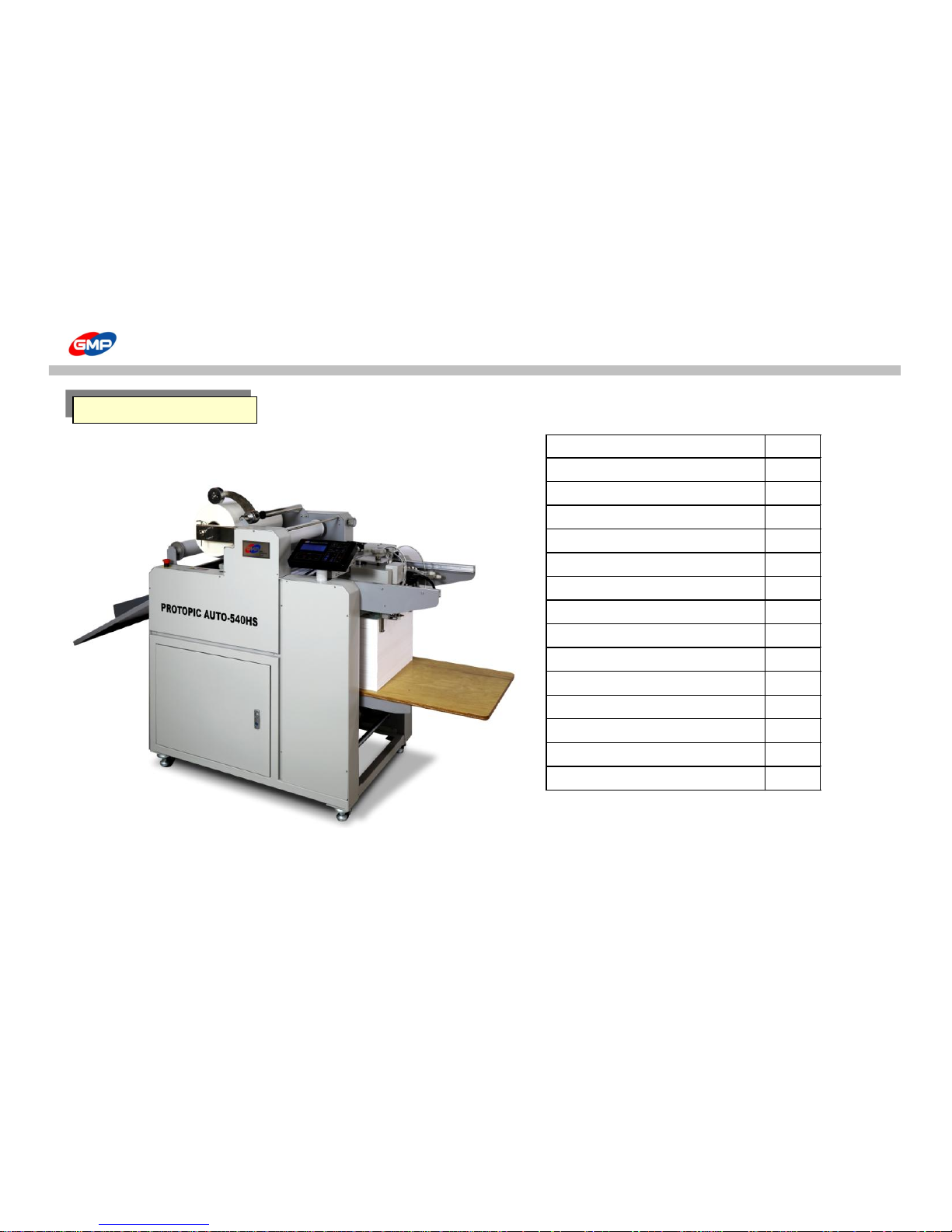
ITEMS Q'TY(EA)
LAMINATOR 1
FEEDING TABLE 1
PAPER GUIDE 2
AIR COMPRESSOR 1
AIR HOSE 1
MANUAL
1
SLEEKING IDLE ROLLER ASS'Y 1
VACUM PUMP
1
SEPARATOR ASS'Y 2
AIR BLOWER ASS'Y 2
REAR GUIDE ASS'Y 2
GLASS TUBE FUSE(20MM) 250V/12.5A 4
WRENCH SET 1
SUCTION CUP 2
`
CONTENTS
PROTOPIC AUTO - 540 HS
10/66
Page 11
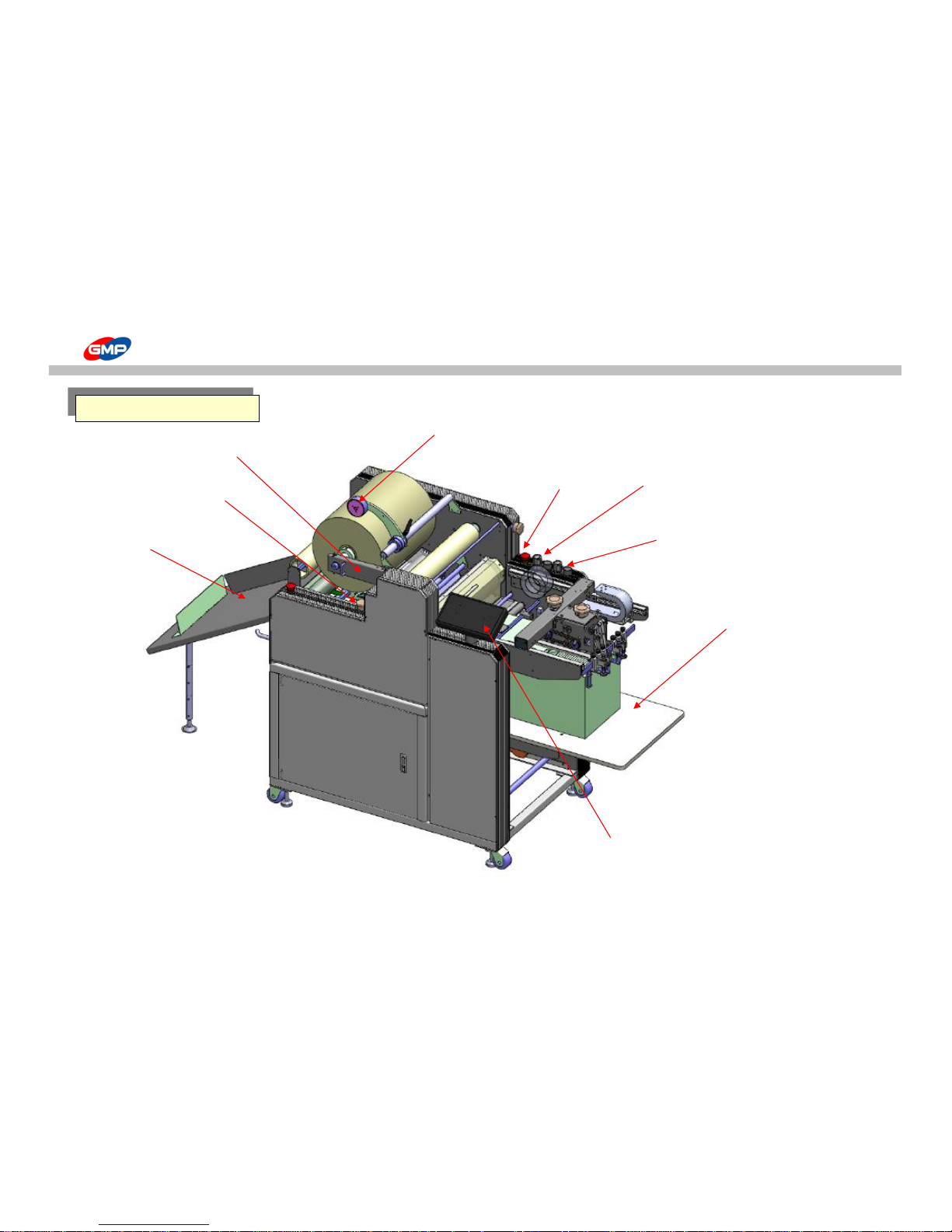
MAIN DEVICES
Main Devices
E-Stop S/W
Feeding Table
Control Panel
Decurling
Adjustment Knob
Film Shaft Holder
Perforator
Pull Roller Pressure
Adjustment Knob
Laminating Roller Pressure
Adjustment Knob
Tray Table
11/66
Page 12
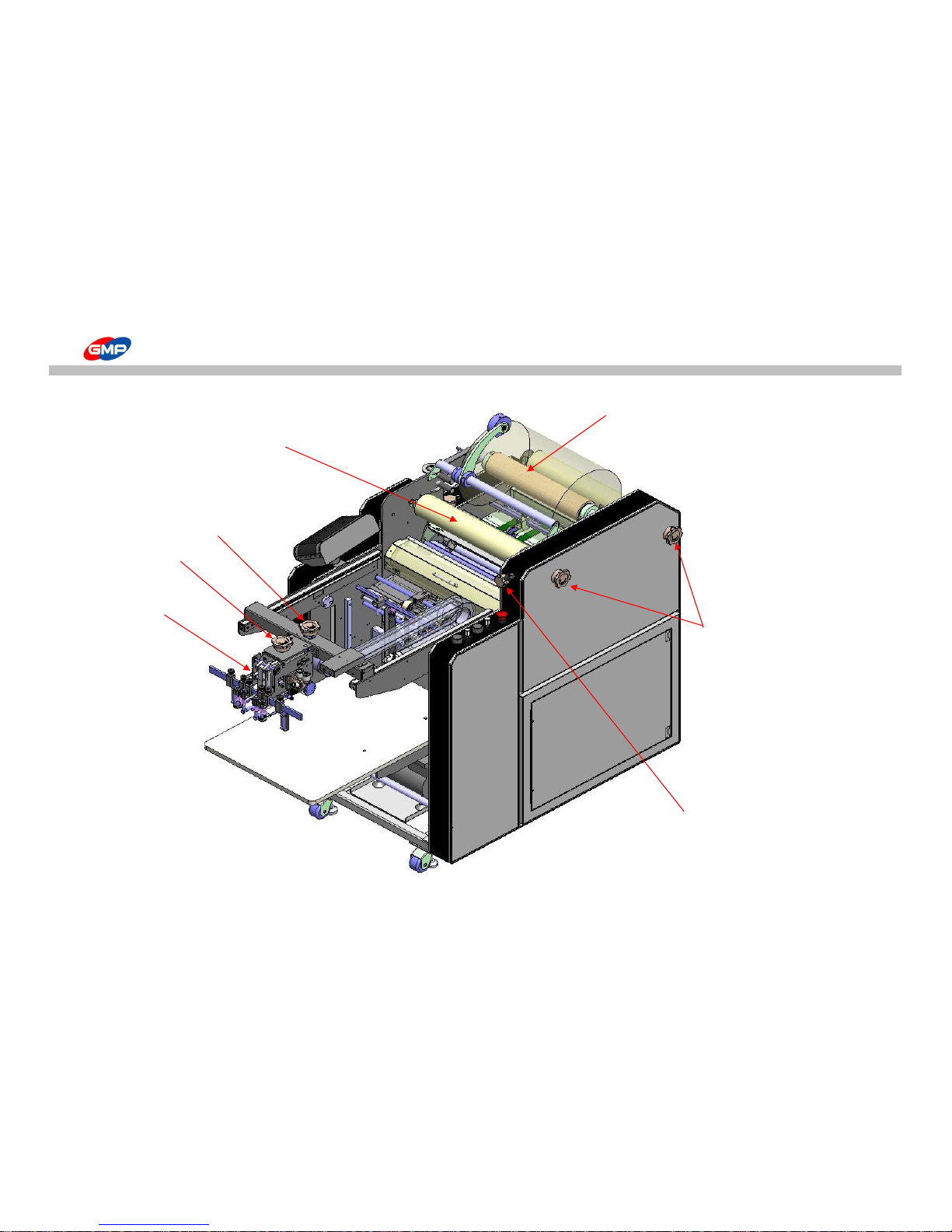
MAIN DEVICES
Feeder
Rewinder
Film Tension Adjustment Knob
Rewinder Tension
Adjustment Knob
Feeder Position
Adjustment Knob
Feeder Height
Adjustment Knob
Film Shaft
12/66
Page 13
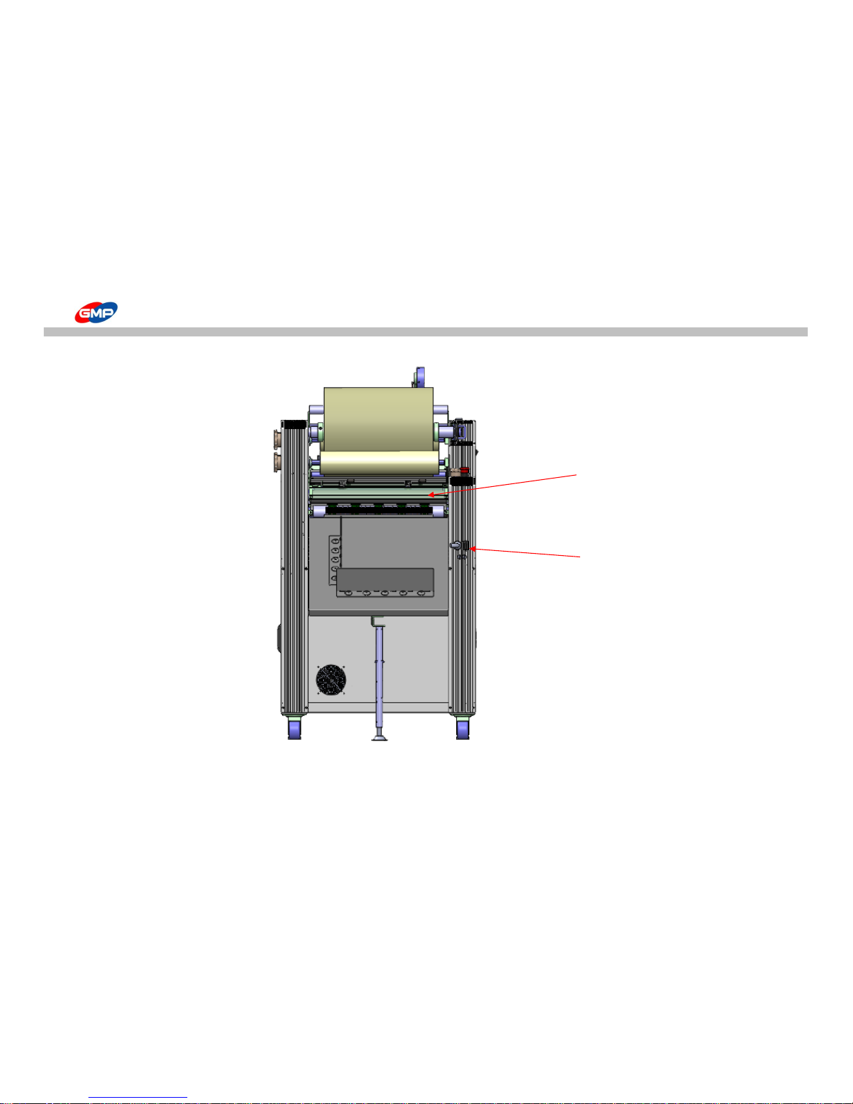
MAIN DEVICES
Power S/W
Bursting Roller
13/66
Page 14
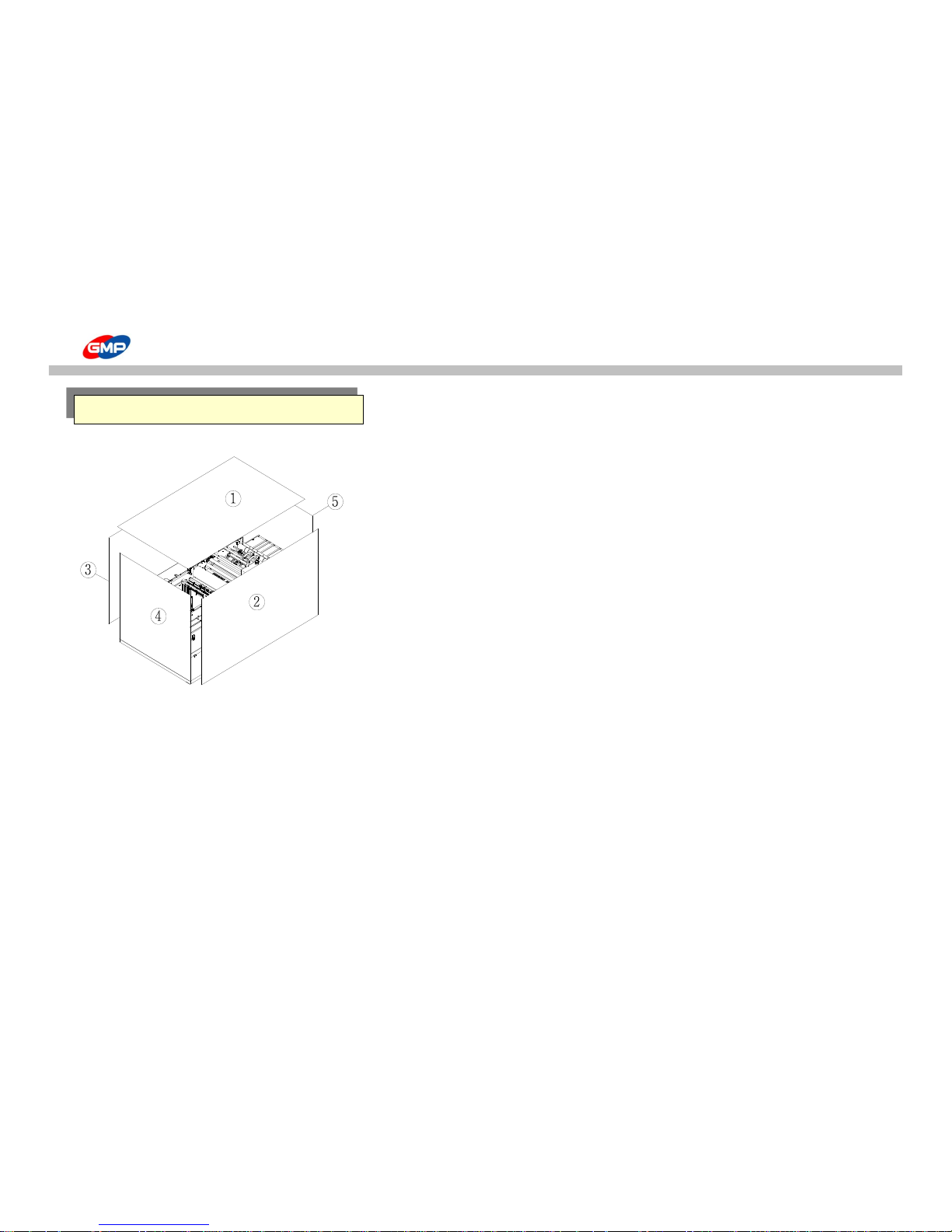
MOVE & INSTALLATION
☞ Unpacking
1. Product is packed with vacuum aluminum packing materials to avoid corrosion and
external packing is wooden crate.
Each wooden panel is assembled with screws to prevent external shock
2. Wooden crate can be disassembled by 11mm box spanner.
Disassemble the 5 panels on the left picture and remove vacuum packing materials. Then,
move it to the installation place.
☞ Move the product
◑ Before it is moved
1. Unplug the power cord & air hose from the laminator.
2. Release the caster wheels and separate the height adjustable legs.
◑ In the following cases, it requires to move it by forklift.
1. If the ground is not level.
2. If it is required to be moved it to more than 10m distance.
3. After unpacking and move it to an installation area.
UNPACK & MOVE
14/66
Page 15
MOVE & INSTALLATION
◑ If it requires to move it by caster wheel.
1. If a distance to move the laminator is less than 10m distance in the same area
2. Move the laminator gently with more than 4 persons at least. During it is moved, grip each corner of the machine.
◑ After the machine is moved
1. Lock the caster wheel and fix the machine with height adjustment legs.
2. Plug the power cord and connect the air hose.
3. Check the machine as the test operation.
WARNING : Machine weight is around 330 kgs, then be careful to move it to avoid damage / injury.
Before it is moved, power cord / air hose have to be unplugged / disconnected.
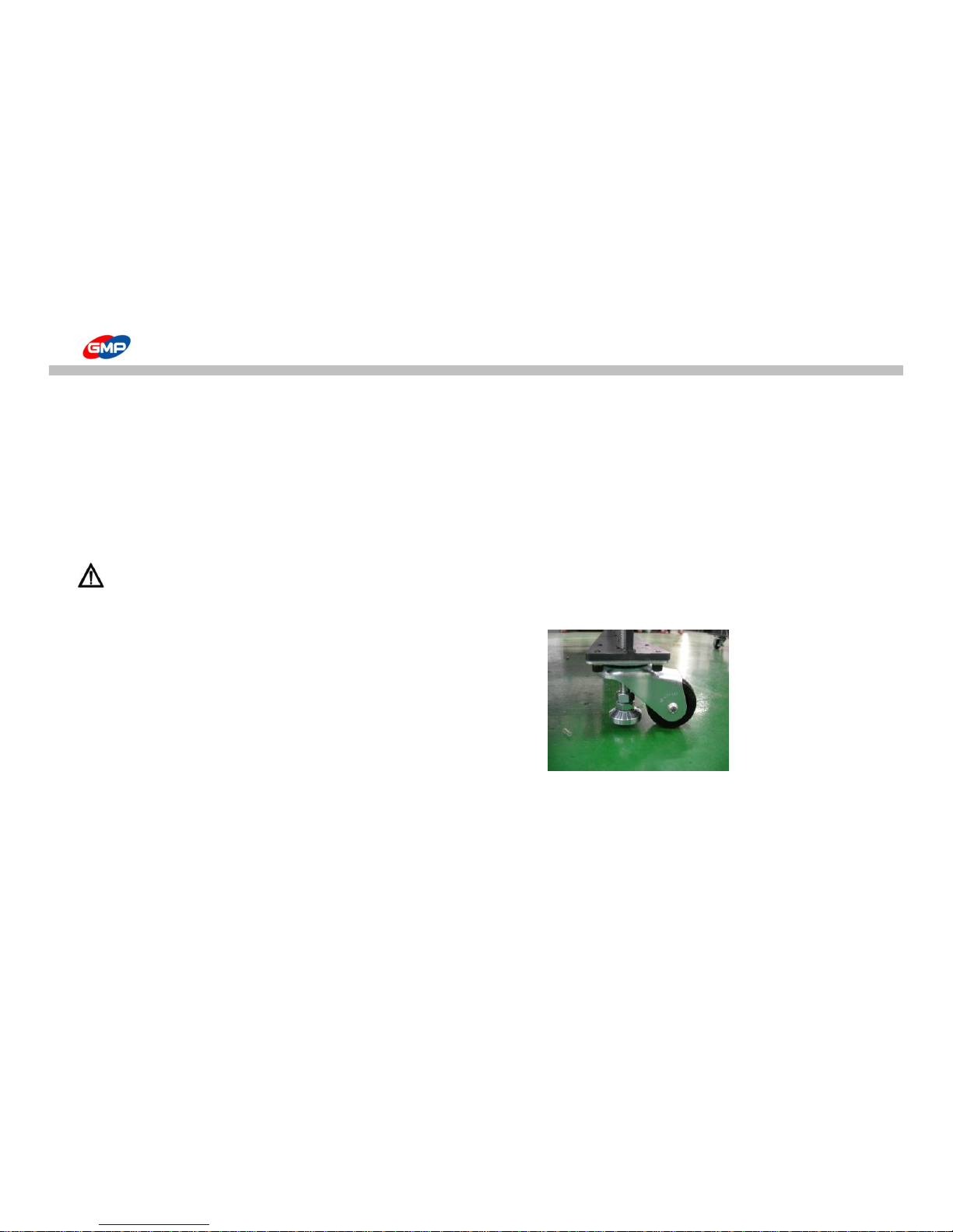
☞ Caster Wheel
Short moving in the same area is required.
☞ Height Adjustment Leg (Leveling Foot)
Leveling foot is to fix / to level the machine.
After the machine is moved on the installation place, fix the machine with spanner.
15/66
Page 16
MOVE & INSTALLATION
☞ Circumstance
1. Be installed in the flat place.
2. If inflammable or combustible substance is around, it might be a reason for a fire.
3. Sufficient ventilation is required to omit the heat from the laminator while laminating.
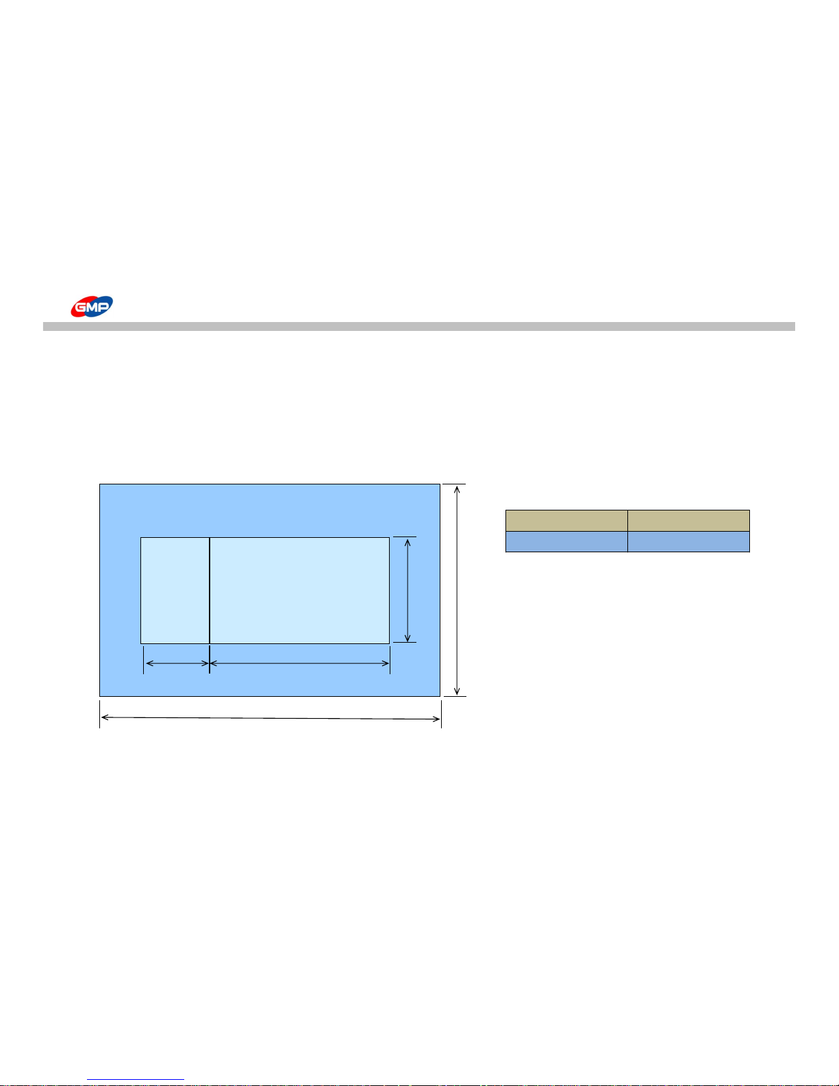
☞Installation Space
Demension(WxLxH) 800*1675(2345)*1320
Working Space(WxLxH) 900*2445*1500
Reference : The place for installation could be different depends on the job circumstance
LAMINATOR
800
1675
2445
900
Paper
Stacker
670
16/66
Page 17
MOVE & INSTALLATION
☞ Power Connection
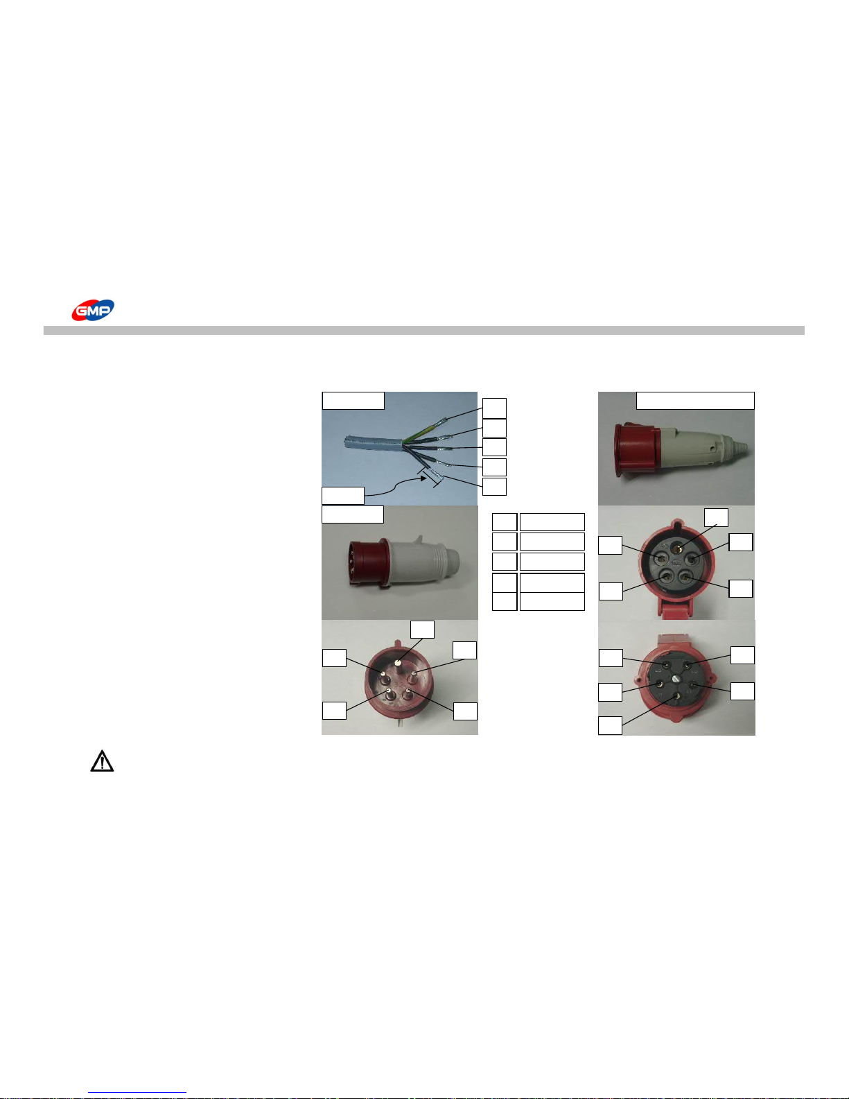
◐ Specification of Main Power
◐ Phase of Plug & Power Socket
Rated Voltage : 3P+N+E, 400VAC
Rated Frequency : 50/60Hz
Rated Current : 23A
◐ Phase & Voltage
1. Phase
G(GROUND)
N(NEUTAL)
L1 ( R )
L2 ( S )
L3 ( T )
2. Line Voltage
N~L1, N~L2, N~L3 : 230VAC
L1~L2, L1~L3, L2~L3 : 400VAC
Warning : If each of phases of powersupply is wrongly connected,
vacumm pump's rotation direction suddenly changed, internal components possibly have fatal damages.
Power Plug
20mm
3
4
5
2
1
Power Cord
3
4
5
2
1
3
4
5
2
1
L1(R)
L2(S)
L3(T)
N(NEUTAL)
G(GROUND)
Power Socket
3
4
5
2
1
5
4
3 2 1
17/66
Page 18
MOVE & INSTALLATION
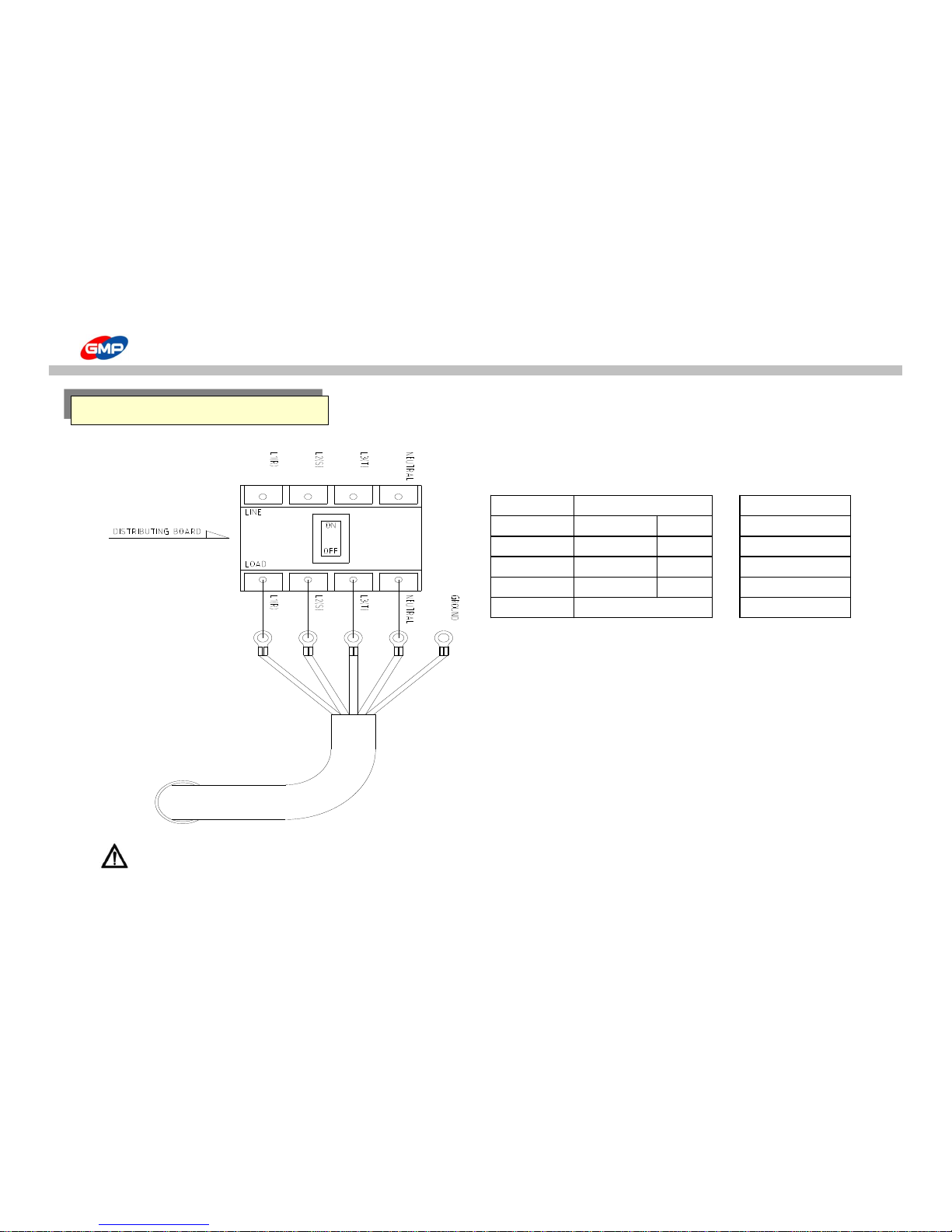
◐ Power Cable is connected directly to the Switchboard
Color&No. of Wire Wiring color
L1 ( R ) Black 1 Black
L2 ( S ) Black 2 Brown
L3 ( T ) Black 3 Black
N(NEUTAL) Black 4 Blue
G(GROUND) Green&Yellow Green&Yellow
Warning : If each of phases of powersupply is wrongly connected,
vacumm pump's rotation direction suddenly changed, internal components possibly have fatal damages.
Connection to Power
18/66
Page 19
MOVE & INSTALLATION
Caution: This product consumes a large amount of electricity during its operation. If you connect this equipment with
a power cable with insufficient capacity or an old cable, a fire might break out due to electrical leakage.
Caution : For your safety, please make sure that it's grounded properly. If not, excessive static electricity will occur during operation
and it will even cause the malfunction of the equipment In case of malfunction or electrical leakage, there's possible danger for electrical shocks.
Caution : If you arbitrarily replace the power plug attached to the product, it might cause a serious problem to your safety.
When you would like to replace the plug, ask for help from the retailer or our service
Caution : Make sure the power is turned off before connecting to the source of electricity.
If not, there's possible danger for injury due to sudden operation of the equipment.
Caution : Do not connect other equipment simultaneously to the consent which is connected to our product.
Due to the excessive power consumption, a fire might break out.
Caution : If you make a wrong phase connection to the source of electricity, it might cause the damage to the equipment or start a fire.
Caution : Insert the plug deeply into the socket so that it won't shake. If not, it's a reason for a fire due to the abnormally heated consent.
Caution : The socket-outlet shall be installed near the equipement and shall be easily accessible.
Caution
Warning
Connection to Power
19/66
Page 20
MOVE & INSTALLATION
☞ How to connect
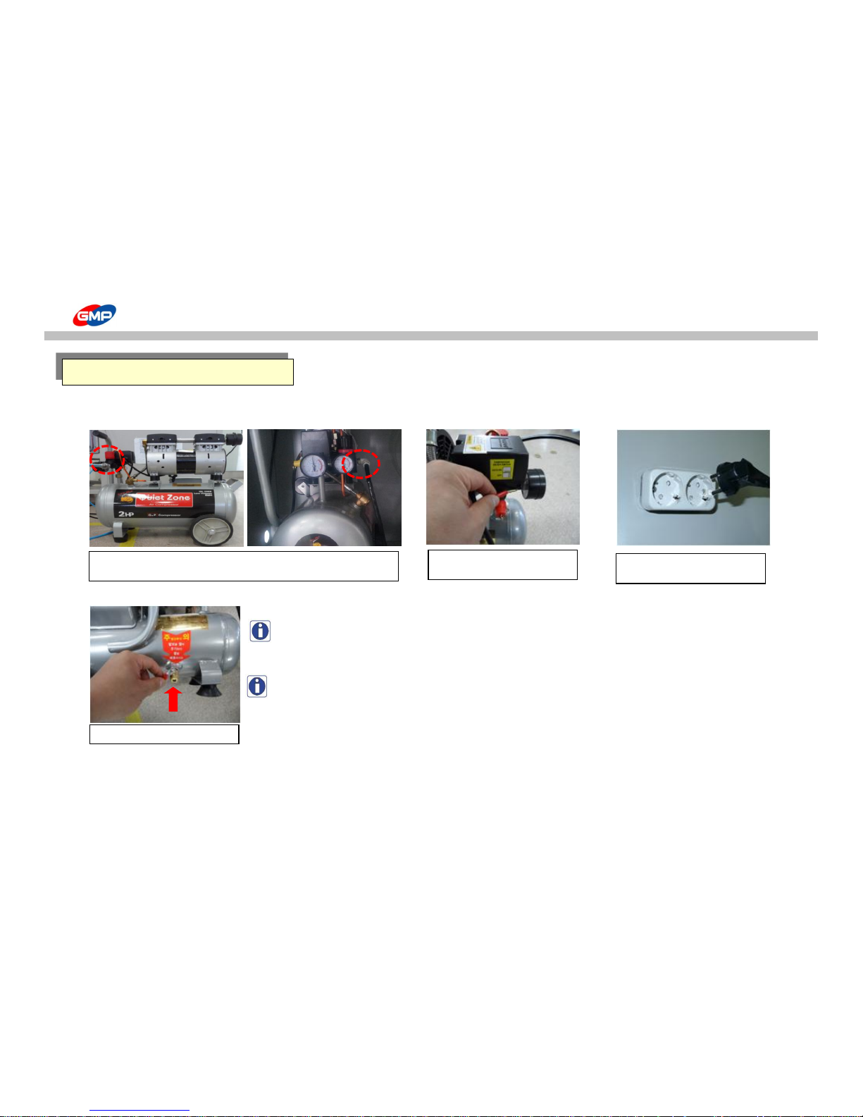
Compressed air needs to be supplied into the laminator to activate the bursting roller and pressure on the laminating roller.
NOTE : A large amount of moisture is made during the air compressor is operated.
Then, the dry filter at output of compressor must be demoisturised once a day.
Power
Plug in at Independent Power System (AC 220~240V).
How to connect Air Compressor
Insert air hose in to the air compressor
After Power On, pull the cap
upward.
Press in the direction of the arrow.
Plug in at Independent Power
System
20/66
Page 21
MOVE & INSTALLATION
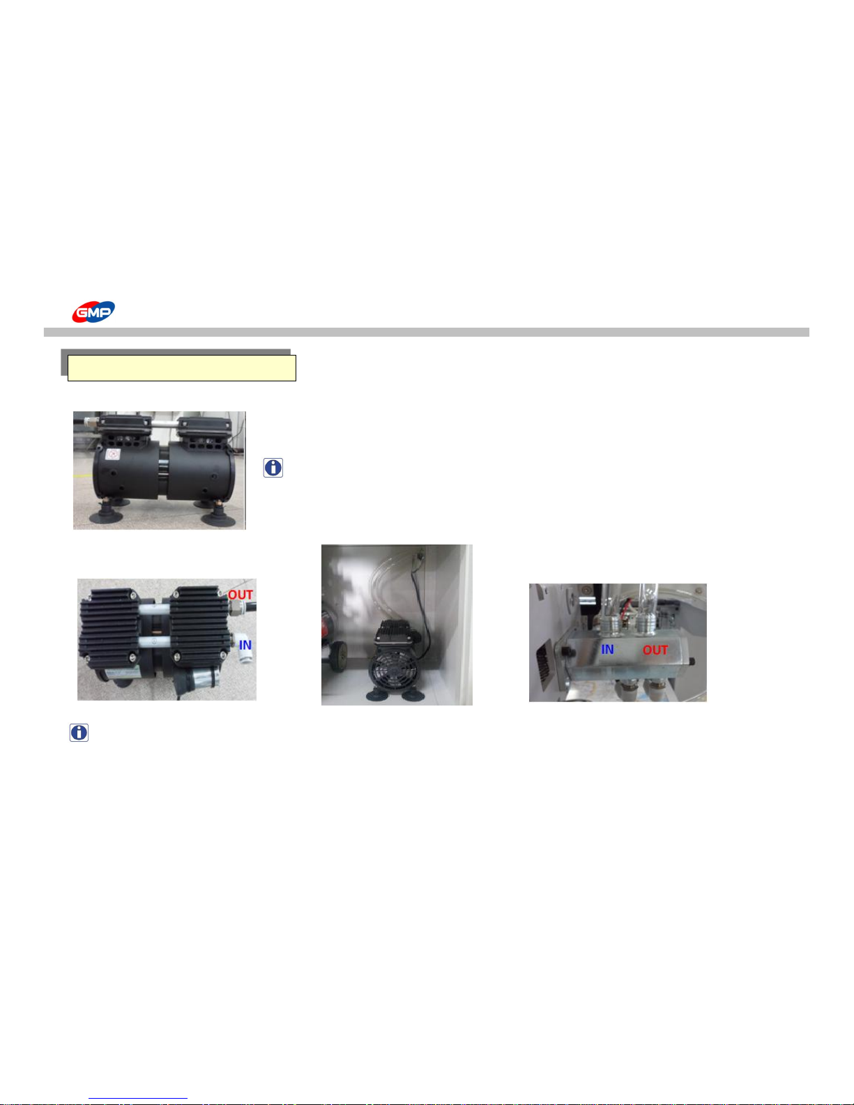
☞ Vacuum Pump
To generate air to feed substrates.
Pressure for Air Compressor is set in the factory and it is recommended to use it at the setting value.
NOTE : If the pressure status of Vacuum Pump is not good, suction/exhaust has to be checked firstly.
Please ask to a supplier.
☞ How to connect
NOTE : Connect the Vacuum Pump with the Feeder as the above pictures.
How to connect Vacuum Pump
IN
OUT
21/66
Page 22
HOW TO USE CONTROL PANEL
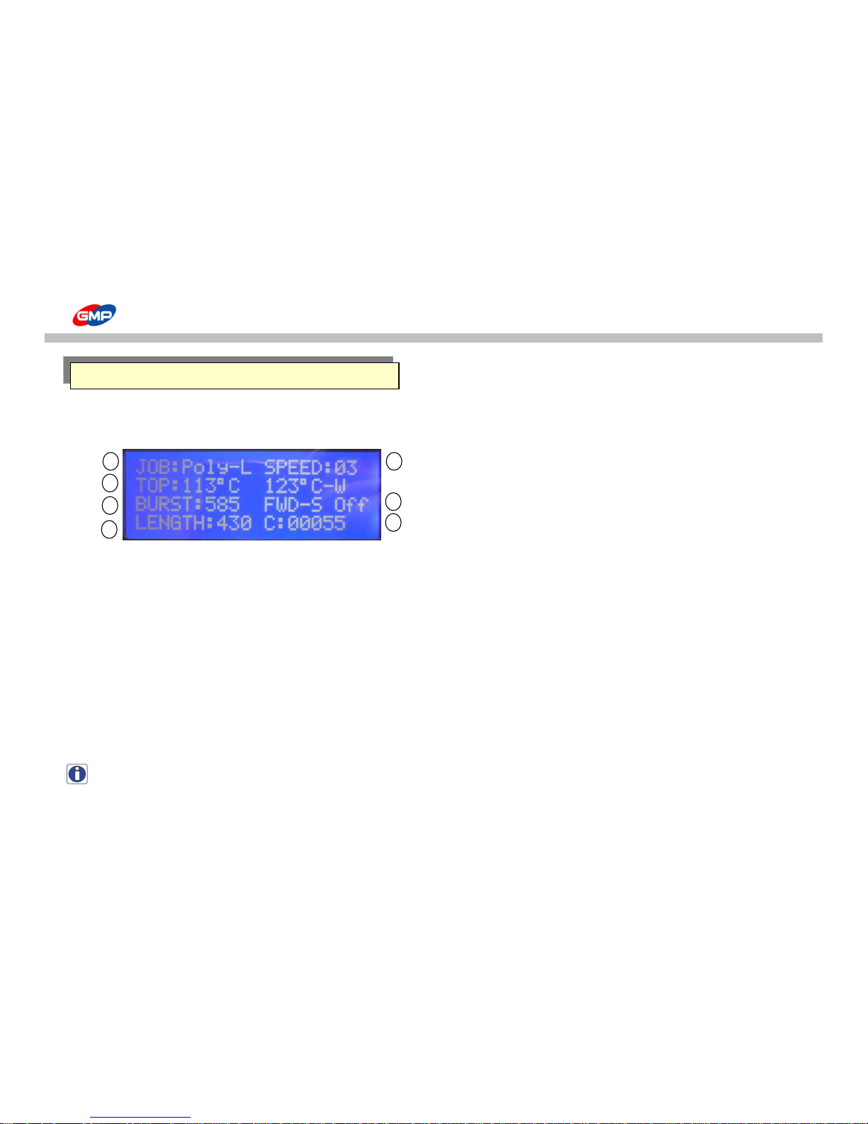
☞ Display Screen is composed of 3 kinds of screens, that is, Main Screen, Sub Screen 1 and Sub Screen 2.
☞ Main Screen : To check the main setting status in the laminator easily.
① "JOB:Poly-L" - for JOB Mode
To save values (temp. / speed for each films) that was set by operator.
This is composed of the below 13 kinds of modes.
JOBS
- Poly-L : Low Temp. operation for Polynex Film (set temp. 100℃) - MICRO : Job with Micronex Film (set temp. 120℃)
- Poly-H : High Temp. operation for Polynex Film (set temp. 120℃) - FOIL-L : Low Temp. operation for Metallic Foil (set temp. 115℃)
- Nylon : Job with Nylonex Film (set temp. 130℃) - FOIL-H : High Temp. operation for Metallic Foil (set temp. 125℃)
- PET-L : Low Temp. operation for Perfex Film (set temp. 90℃) - User-1 : Setting Job by operator 1
- PET_H : High Temp. operation for Perfex Film (set temp. 110℃) - User-2 : Setting Job by operator 2
- FUS-L : Low Temp. operation for Fusing(Sleeking) Film (set temp. 125℃) - User-3 : Setting Job by operator 3
- FUS_H : Hight Temp. operation for Fusing(Sleeking) Film (set temp. 135℃)
NOTE : Refer to the "JOB" button functionality to check / save setting values.
Details for Display
1
2
3
4
5
6
7
22/66
Page 23

HOW TO USE CONTROL PANEL
② "TOP:113℃ 123℃-W" - for display of Temp. & Jobs
To display Setting / Current Temp. of Laminating Roller and Job Availability. Setting Temp. Range is "0~150℃".
- "W"(WAIT) : means "not ready for lamination" (temp. is too low or too high for lamination).
- "R"(READY) : means "ready for lamination".
NOTE : Refer to "Buttons" functionality for how to set temp.
③ "BURST" - for display of substrate cutting size
To display operation time for bursting roller. Setting Bursting Point Range is Min. "580"~ Max. "660".
Recommendable Setting Value is 610~620.
NOTE : Refer to "Buttons" functionality for how to set bursting time.
④ "LENGTH" - for display of substrate length
Displayed value means substrate length. Setting value of substrate length is a required length for lamination.
Setting substrate length range is 250~800mm.
NOTE : Refer to "Buttons" functionality for how to set substrate length.
⑤ "SPEED" - for display of roller speed
To display rotation speed of laminating roller. Speed setting range is Min. "1" ~ Max. "15".
NOTE : Start at low speed for initial stage of job.
⑥ "FWD-S OFF" - for display of status for LAMINATOR MAIN MOTOR.
- FWD-S : Forward Operation is stopped.
- REV-R : Reverse Operation is being processed.
- FWD-R : Forward Operation is being processed.
- JOG : In JOG status
- REV-S : Reverse Operation is stopped.
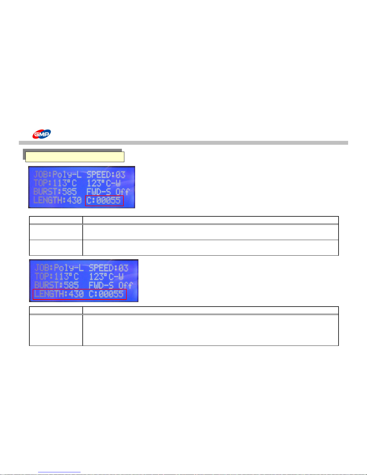
⑦ "C:00055" - for display of daily lamination q'ty
To display q'ty of laminated results for a certain period. It can be reset if it is required.
NOTE : Refer to "Button" functionality for how to reset counter.
23/66
Page 24
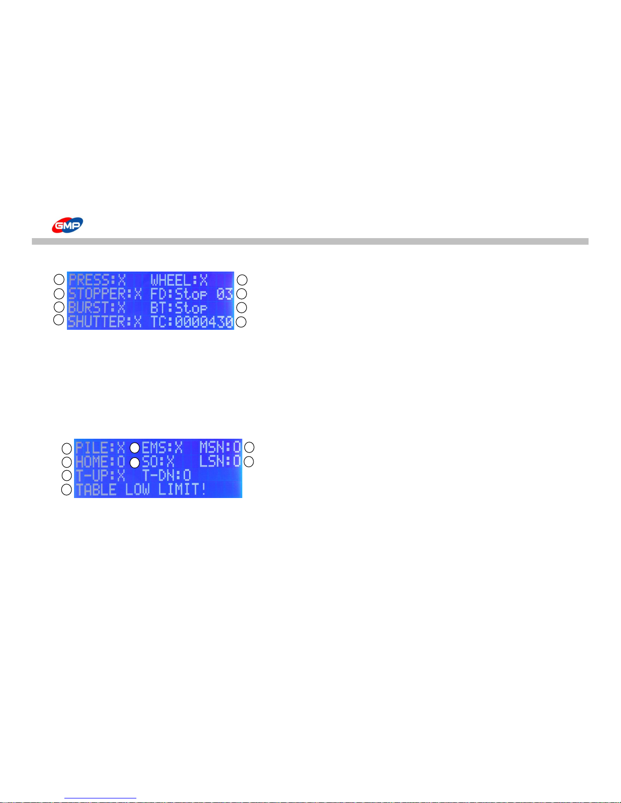
HOW TO USE CONTROL PANEL
☞ Sub-Screen 1 : To check cylinders & motors operation status manually.
① PRESS : Display operation status of MAIN ROLLER.
Press SPEED button to operate it manually.
② STOPPER : Display operation status of STOPPER.
Press MAIN SCREEN MODE button to operate it manually.
③ BURST : Display operation status of BURST. Press JOB button to operate it manually.
④ SHUTTER : Display operation status of SHUTTER. Press TABLE UP button to operate it manually.
⑤ WHEEL : Display operation status of WHEEL. Press TABLE DOWN button to operate it manually.
⑥ FD : Display operation status of FEEDER MOTOR. Press MANUAL RUN button to operate it manually and speed also can be adjusted.
⑦ BT : Display operation status of BURST MOTOR. Press BURST POSITION button to operate it manually.
⑧ TC : Display TOTAL COUNTER.
☞ Sub-Screen 2: Display operation status of SWITCH & SENEOR
① PILE : Display operation status of PAPER PILE DETECT MICRO SWITCH.
② HOME : Display operation status of FEEDER HOME SENSOR.
③ T-UP & T-DN : Display operation status of TABLE UP & DOWN LIMIT SWITCH.
④ NORMAL STATUS! : If an error is occurred, message would be displayed.
⑤ EMS : Display operation status of EMERGENCY SWITCH.
⑥ SO : Display operation status of MIS-FEEDING SENSOR OVERRIDE.
Press MANUAL RUN button to operate MISFEEDING SENSOR manually.
- SO(SENSOR OVERRIDE) ON status : if the sensor detect, system is not stopped.
- SO(SENSOR OVERRIDE) OFF status : if the sensor detect, system is stopped.
⑦ MSN : Display operation status of MIS-FEEDING SENSOR.
⑧ LSN : Display operation status of LOADING SENSOR.
1
2
3
4
5
6
7
8
1
2
3 4 7
8
5
6
24/66
Page 25
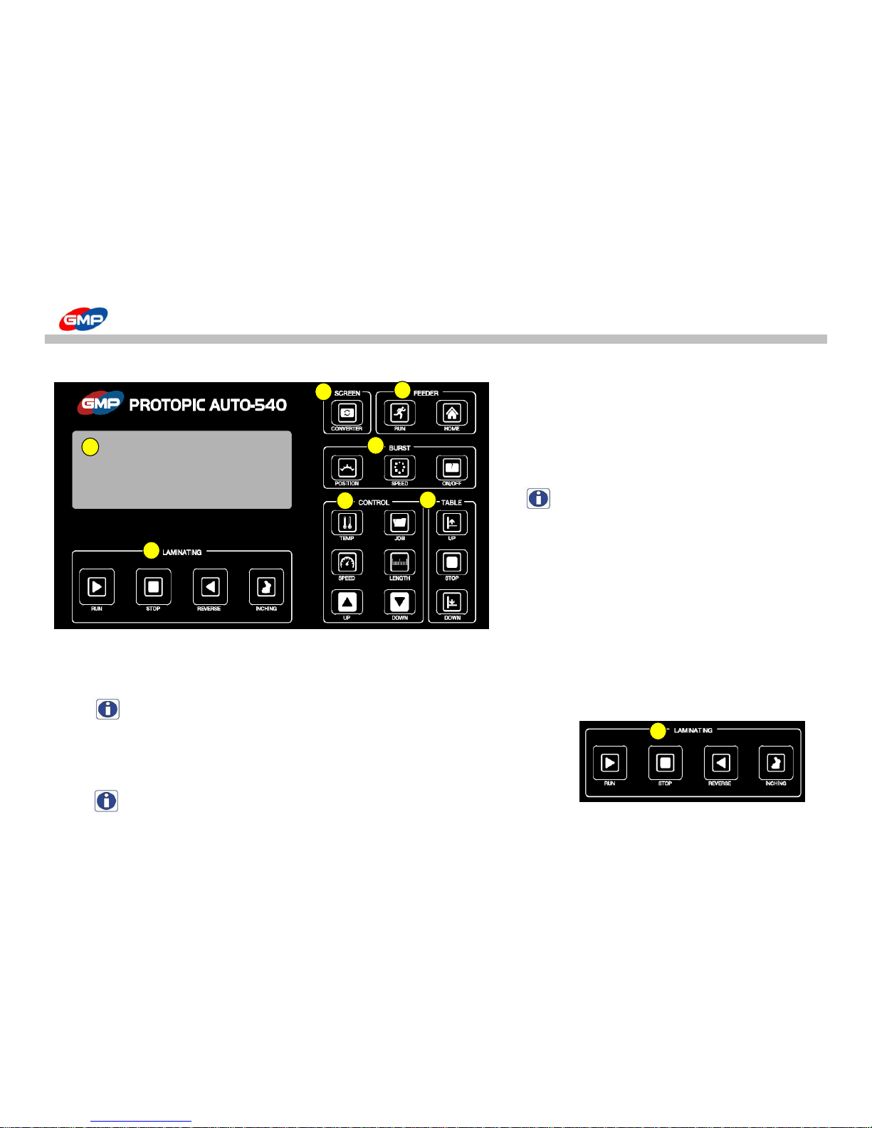
HOW TO USE CONTROL PANEL
☞ Individual Buttons' functionality : In state of the machine turning on, the buttons' functionality are explained.
A. LAMINATIG
"RUN" : It is to activate the machine.
If pressing the button, the laminating roller starts
to be pressurized and rotates, and also the vacuum pump
and feeding device are activated.
NOTE : In the stop mode, the excessively high
speed of rotation can result in the job error.
"STOP" : It is to stop the operation of machine.
If pressing the button, the pressure state of
laminating roller is lifted, then the roller's
rotation & feeding operation stops.
"REVERSE" : It is to rotate the roller reversely.
While the button is pressed, the roller rotates reversely with state of pressurization.
If the button is not touched, the reverse rotation stops and the laminating roller is depressurized.
NOTE : this function is not activated during the operation.
"INCHING" : It is to rotate the laminating roller, pull roller except for the feeding device.
As long as the menu is selected, each roller rotates. If the selection is lifted, the rotation stops.
NOTE : Please use this menu for the roller cleaning or laminating job preparation.
A C E D F
B A G
25/66
Page 26
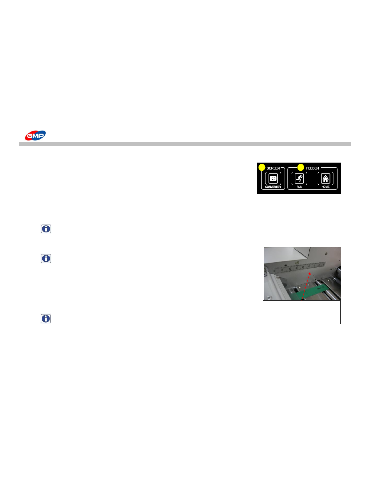
HOW TO USE CONTROL PANEL
B. SCREEN "CONVERTER"
It is to change the LCD screen mode showing the laminating status.
If pressing the button, the screen is converted into the main screen, sub screen1, sub screen2.
C. FEEDER
"RUN" :
it is to operate or stop VACUUM PUMP manually.
If pressing the button, the vacuum pump is activated under ON state. One more press put the operation in OFF position.
NOTE : In the normal laminating state, the vacuum pump maintains the ON state when we could press"RUN" to put it in OFF state.
"HOME" : It is to put the feeder on the home position(feeding ready state).
If pressing the button, the feeder goes to the home position.
NOTE : the feeding table doesn't go up if the feeder is not in the home position.
D. BURST
"POSITION" :
It is to change the bursting position. Bursting position setting range is "580~660"mm.
- Bursting Position Setting : After pressing the button, set the bursting position
by using UP/DOWN buttons. 5 seconds later, the input data is saved automatically.
NOTE : According to the substrate's characteristics, thickness, decuring's height
and laminating speed, the bursting timing could be changed.
Do adjust the position by checking the bursting status. Normal span of position ranges from 610 to 620
When setting the bursting roller
position, use the scale attached
to the machine.
C
B
26/66
Page 27
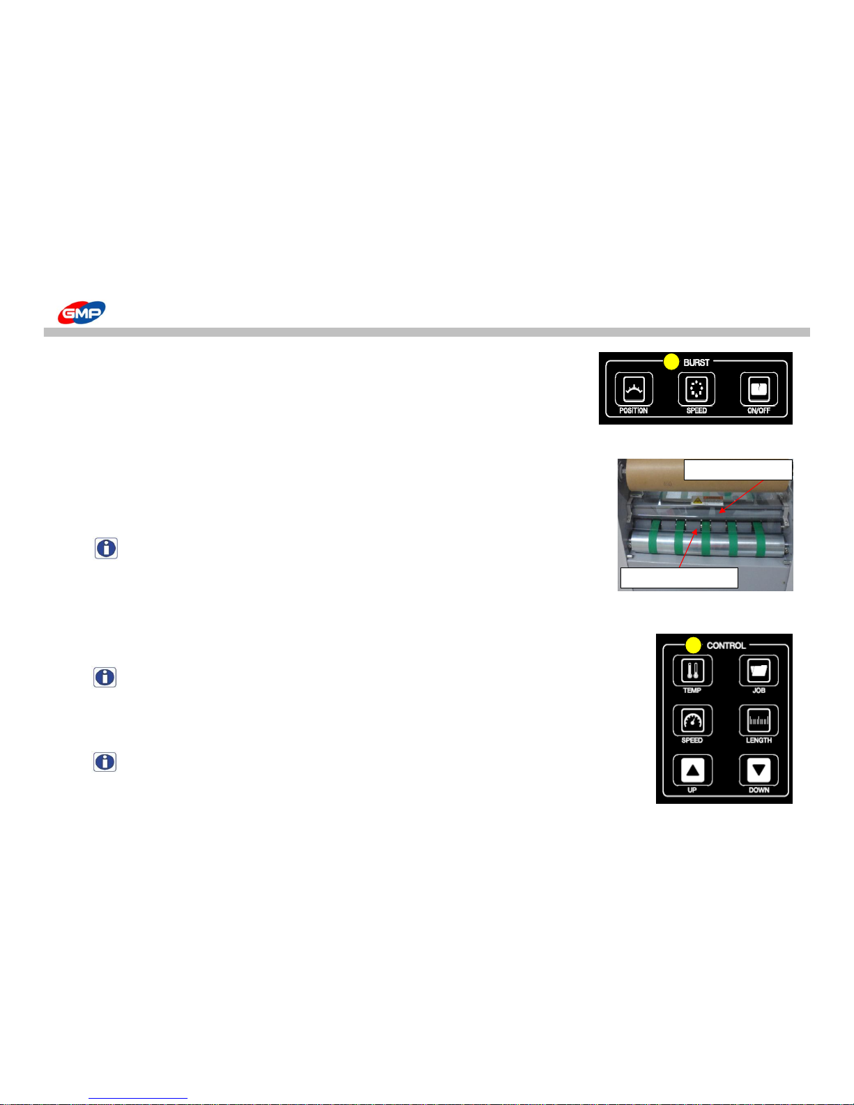
HOW TO USE CONTROL PANEL
"SPEED" :
In case of the lamination using NYLONEX(NYLON) & PERFEX(PET), rotate the bottom bursting roller
in high speed to increase the film bursting quality. If the lamp is lit by pressing the button,
the bottom roller run in high speed. But one more press of button makes the bottom roller run
at normal speed.
"ON/OFF" :
It is button that moves the upper roller upward/downward.
After selecting the button, if the lamp is lit on, the upper roller is operated.
If pressing the button one more to turn off the lamp, the upper roller stops.
NOTE : In the RUN state, the button is activated. The button is not activated in STOP state.
E. CONTROL
"TEMP" :
It is to set the roller's temperature.The temperature setting is "0 ~ 150"C.
- Temperature setting : After pressing the button, set the desired temperature with UP/DOWN buttons in state of "(ON)".
NOTE : In the state of 'STOP', if pressing "TEMP" BUTTON for over 3 seconds, reset "DAILY COUNTER".
"SPEED" :
To adjust the setting value of laminating speed. Speed setting range is "1 ~ 15".
- Speed Setting : press "SPEED" button and adjust the speed with UP/DOWN buttons.
NOTE : Speed is changed in "RUN" status only.
Upper Bursting Roller
Bottom Bursting Roller
D
E
27/66
Page 28
HOW TO USE CONTROL PANEL
"JOB" :
It is to change Job mode. There are 13 kinds of JOB modes.
- JOB mode selection : after the button is pressed, select the job mode desired according to the film kinds.
It is possible that the user input the data of temperature, paper length, bursting position. 5 seconds later, the input data is saved automatically.
NOTE : [Fatory Setting Progress]
- in "Poly-L" Mode, if pressing "SPEED" and "STOP" buttons together the input data get back to the factory setting value.
"LENGTH" :
To set up the substrate length. Substrate length setting range is "254 ~ 800"mm.
- Substrate's length setting : after the button is pressed, set the length by using UP/DOWN button.
5 seconds later, the input data is saved automatically.
NOTE : This machine is the way of 'UNDERLAP'feeding, so, the paper length should be set about 3~5 smaller
than actual paper size.
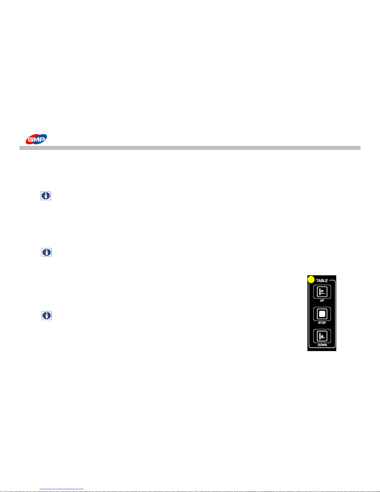
F. TABLE "UP/DOWN/STOP"
It is to make the feeding table up, down and stop.
If pressing "TABLE UP" button, the feeding table goes up as long as the button is touched.
If pressing "TABLE DOWN", the feeding table goes down, but it stops if pressing "TABLE STOP".
NOTE : The feeding table doesn't go up if it is not in the feeding ready state.
-> By selecting "FEEDER HOME" menu, put the feeding table in the ready state(home position).
G. "LCD"
LCD shows the current setting for Laminator. If the power is on to the machine and it is turned on,
LCD screen becomes lit on. For more detailed information, refer to "Description on Display".
F
28/66
Page 29
ERROR MESSAGE
Cause of Trouble / How to troubleshoot
If the communication (RS232C) between the main PCB & display PCB is in trouble, the message
as the above picture would be blinking for every 0.5 sec till it would be recovered.
If the communication (RS232C) between the main PCB & display PCB is in trouble, the message
as the above picture would be blinking for every 0.5 sec till it would be recovered.
To display Alarm for Main Motor Drive.
If input/output voltage is not be at the Motor Drive or encoder for motor control is defective, LAMI DRIVE ALARM is occurred.
While this alarm is cured, if the RUN button is pressed, the alarm message is displayed for 3 secs.
To release from alarm, press STOP button for 1 sec on SUB2 Mode.
ERROR MESSAGE
ERROR MESSAGE
COM1 ERROR
COM2 ERROR
Cause of Trouble / How to troubleshoot
LAMI DRIVE ALARM
Main Screen ERROR Messages
29/66
Page 30
ERROR MESSAGE
To display Alarm for Burst Motor Drive
If input/output voltage is not be at the Motor Drive or encoder for motor control is defective, LAMI DRIVE ALARM is occurred.
While this alarm is cured, if the RUN button is pressed, the alarm message is displayed for 3 secs.
To release from alarm, press STOP button for 1 sec on SUB2 Mode.
To display Alarm for Feeder Motor Drive
If an overload on the Motor, the alarm is occurred. Please check the drive status.
While this alarm is cured, if the RUN button is pressed, the alarm message is displayed for 3 secs.
To release from alarm, press STOP button for 1 sec on SUB2 Mode.
To display Alarm for Table Motor Drive
If an overload on the Motor, the alarm is occurred. Please check the drive status.
While this alarm is cured, if the RUN button is pressed, the alarm message is displayed for 3 secs.
To release from alarm, press STOP button for 1 sec on SUB2 Mode.
To display Error for TBL UP LIMIT DETECT
When the Table Up limit S/W is ON, if RUN button is pressed, the alarm message is displayed for 3 secs.
Please check the Feeder Table Up Limit S/W.
To display Error for LAMI EMS & COVER OPEN
When the Laminator is in emergency stop and Safety cover is opened, if RUN button is pressed, the alarm message is
displayed for 3 secs.
Please check "E-stop S/W", "Safety Cover" and "Burst Safety Cover".
To display Error for Feeder E-Stop
When the Feeder E-Stop button is pressed, if RUN button is pressed, the alarm message is displayed for 3 secs.
Please check Feeder E-Stop S/W.
To display Error for Feeder Origin Point
When the feeder is not at origin point, if RUN button is pressed, the alarm message is displayed for 3 secs.
Please press "FEEDER HOME" button on CONTROL PANEL to position the feeder motor at origin point.
TBL UP LIMIT DETECT
LAMI EMS & COVER OPEN
FEEDER EMS PRESSED
FEEDER NOT HOME POS
BURST DRIVE ALARM
FEEDER DRIVE ALARM
TABLE DRIVE ALARM
30/66
Page 31
ERROR MESSAGE
Alarm for Main Drive
To release from alarm, press STOP button for 1 sec on SUB2 Mode.
Alarm for Burst Drive
To release from alarm, press STOP button for 1 sec on SUB2 Mode.
Alarm for Feeder Drive
To release from alarm, press the TABLE STOP button for 1 sec on SUB2 Mode.
Alarm for Table Drive
To release from alarm, press the RUN button on SUB mode the alarm message for 3 secs.
Error for Feeder E-Stop
Please check the Feeder E-Stop button.
E-stop and Safety Cover is opened.
Please check the E-stop, Safety Cover and Burst Safety Cover.
Table Up Limit is ON
Please check the Table Up Limit S/W.
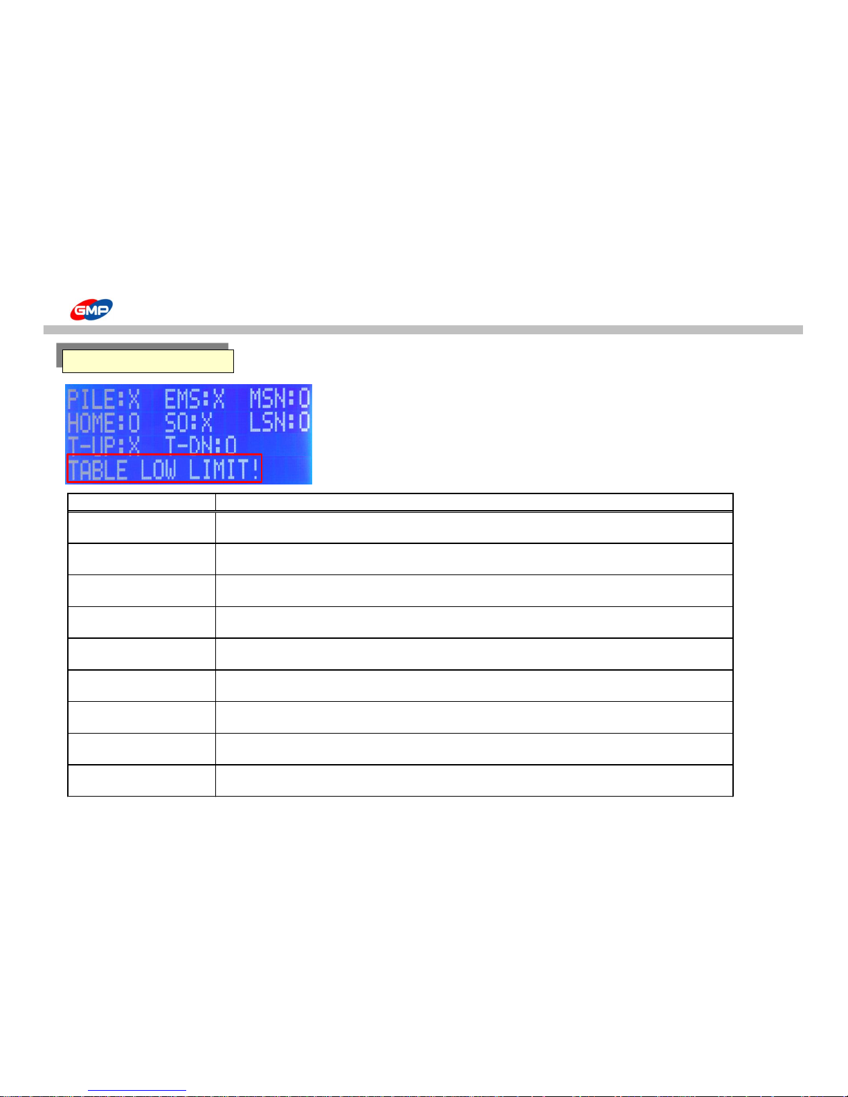
Table Down Limit is ON
Please check the Table Down Limit S/W.
Normal Status.
TABLE DRIVE ALARM
FEEDER EMS PRESSED
LAMI EMS&COVER OPEN
TABLE UP LIMIT
TABLE LOW LIMIT
NORMAL STATUS
Cause of trouble and How to troubleshoot
ERROR MESSAGE
LAMI DRIVE ALARM
BURST DRIVE ALARM
FEEDER DRIVE ALARM
Sub-Screen ERROR Messages
31/66
Page 32

ERROR MESSAGE
Message for STAND-BY status
STAND BY STATUS
Display FIGURE_W STAND BY
POWER OFF STATUS
Display FIGURE_X POWER OFF
Display of Stand-by Time
display the STAND-BY mode
- If laminating roller setting temp. and real temp. is higher than 80℃, but system is in stop status, the STAND BY time is measured.
2 hours are passed from the measured time, the machine is in STAND BY mode.
In the STAND BY mode, message of STAND BY STATUS is blinking on LCD PANEL.
- Release from STAND BY mode : Press RUN button in STAND BY mode.
Display of POWER OFF status
display the POWER OFF mode
- 1 hour is passed from the STAND BY mode, the machine is in POWER OFF mode.
In the POWER OFF mode, LCD Back Light is OFF. When the machine is back to normal mode, the LCD Back Light is ON.
- Release from POWER OFF mode : Press RUN button in POWER OFF mode.
32/66
Page 33
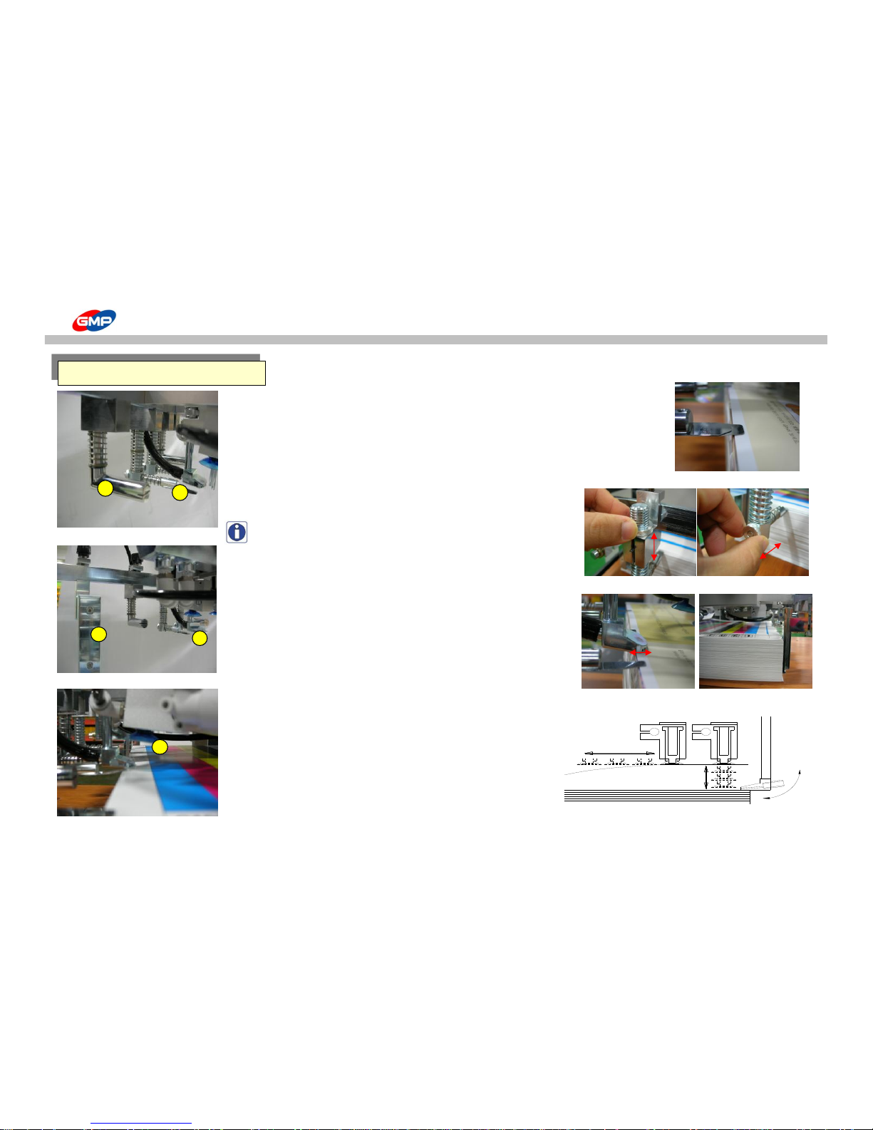
How to use the Main Devices
① - SEPARATOR
To prevent pick more than 2 sheets for feeding and
to prevent twist the sheets by blower.
Install it as the right picture and recommendable pressed area is 5mm.
② - BLOWER
To provide air in-between the sheets to make easy to separate
the sheets for feeding.
NOTE : The separator & the blower position are adjustable as the
right picture. If the separator pressure would be too high,
this could be a cause of feeding error.
③ - BLAST FOOT
To blow air between picked sheet and stacked sheets to make easy
to feed sheet to the feeding wheel.
Adjust the feeder position and install it as the right picture.
Recommendable pressed area is 7~8mm.
④ - REAR GUIDE
To prevent sheets move backward in feeding process.
⑤ - PICK UP CUP
To pick up a sheet to ready for feeding.
Recommendable sheet pick-up height is 20mm.
1
2
Operation of Pickup Cup and Blast Foot
example for Separator
Installation
Example for installation of Blower & Rear Guide
Feeding Area
33/66
Page 34
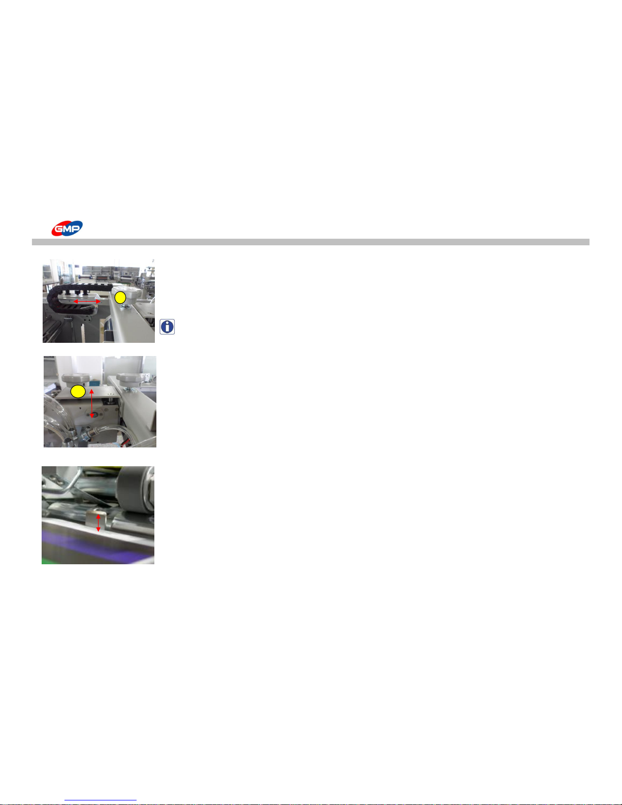
How to use the Main Devices
⑥ - Feeder Fixing Knob
To fix a position of Feeder
Adjust its position for stacked sheets and fix it.
NOTE : If the Feeder would not be fixed, this could be a cause of damage on the feeder while lamination.
⑦ - Feeder Height Adjustment Knob
Adjust the Feeder height position.
If the feeding table would be moved upward as the below picture,
recommendable distance between sheets and alignment device is 3~5mm.
3~5mm
6
7
34/66
Page 35
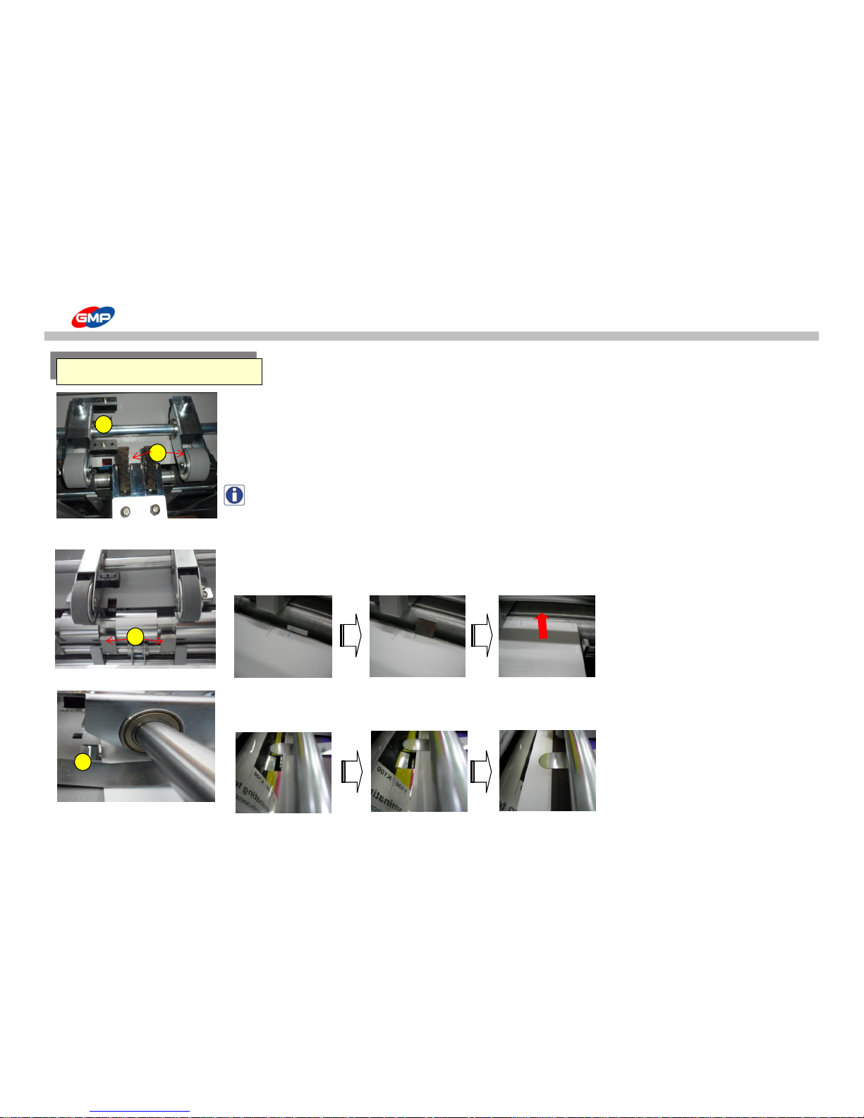
How to use the Main Devices
① - Misfeeding Sensor
To prevent contamination on laminating roller, if an error for feeding is occurred.
When the feeding is stopped by feeding error, it stops machine operation.
② - Feeding Wheel & Brush
To feed substrates to the Laminating Roller.
NOTE : Conditions of substrates could require adjustment of left/right pressure on feeding wheel.
Ex) If a pressure on right feeding wheel is higher, substrates will be moved to the left to the laminating roller.
In this above case, loosen the right wheel fixing bolt.
③ - Substrate Stopper
To make substrate stand-by for feeding. It make substrate in stand-by & aligned status
for a certain period and at the feeding time, the shutter is opened for feeding.
④ - Substrate Alignment
To align substrates. Align substrates from the feeder and when the feeding wheel is operated,
the shutter is opened to move substrate to the laminating roller.
3
Feeding Area
1
2
Stand-By
Shutter-Opened
Feeding
4
Stand-By
Shutter-Opened
Feeding
35/66
Page 36
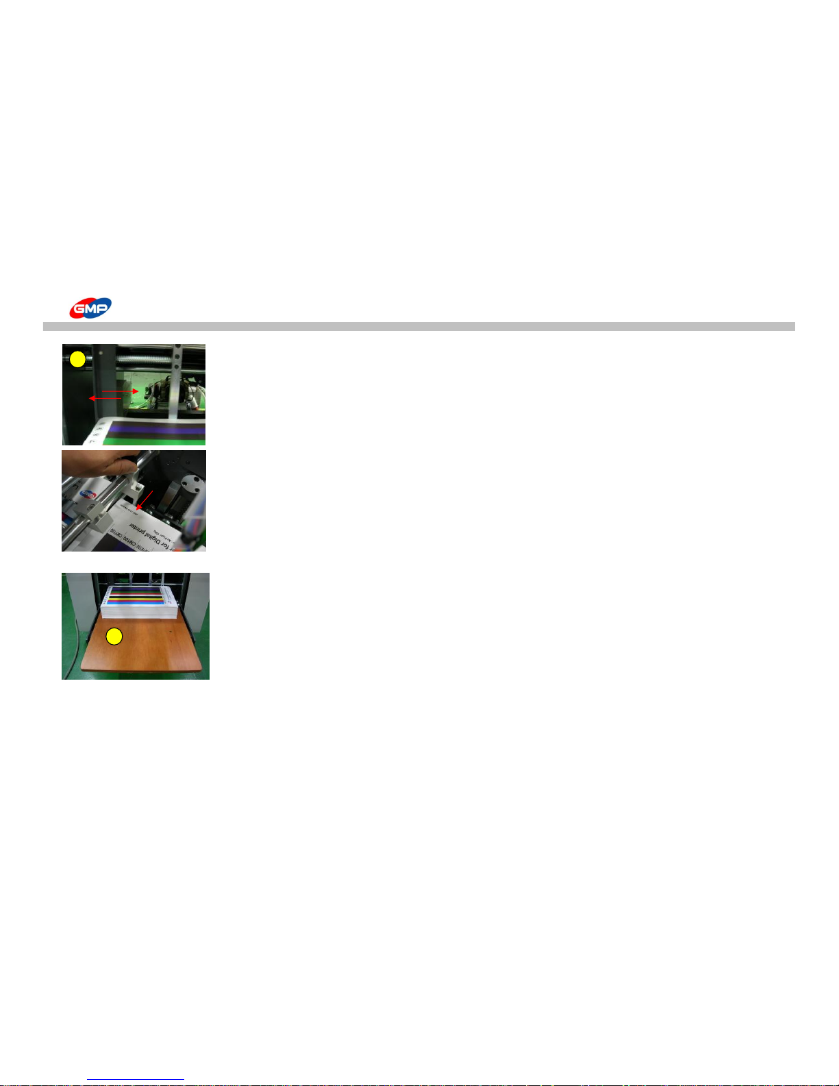
How to use the Main Devices
⑤ - Substrate Guide
To pile up substrates, this guide is to avoid paper twist trouble in feeding / alignment process.
Adjust position of guide for substrate size and stack substrates.
⑥ - Feeding Table
To pile up substrates for lamination.
Min. substrate size for stacking is "W 210mm X L 254mm" and Max. one is "W 540mm X 750mm".
Substrate length setting range is Min. "254" ~ Max. "800".
5
6
36/66
Page 37
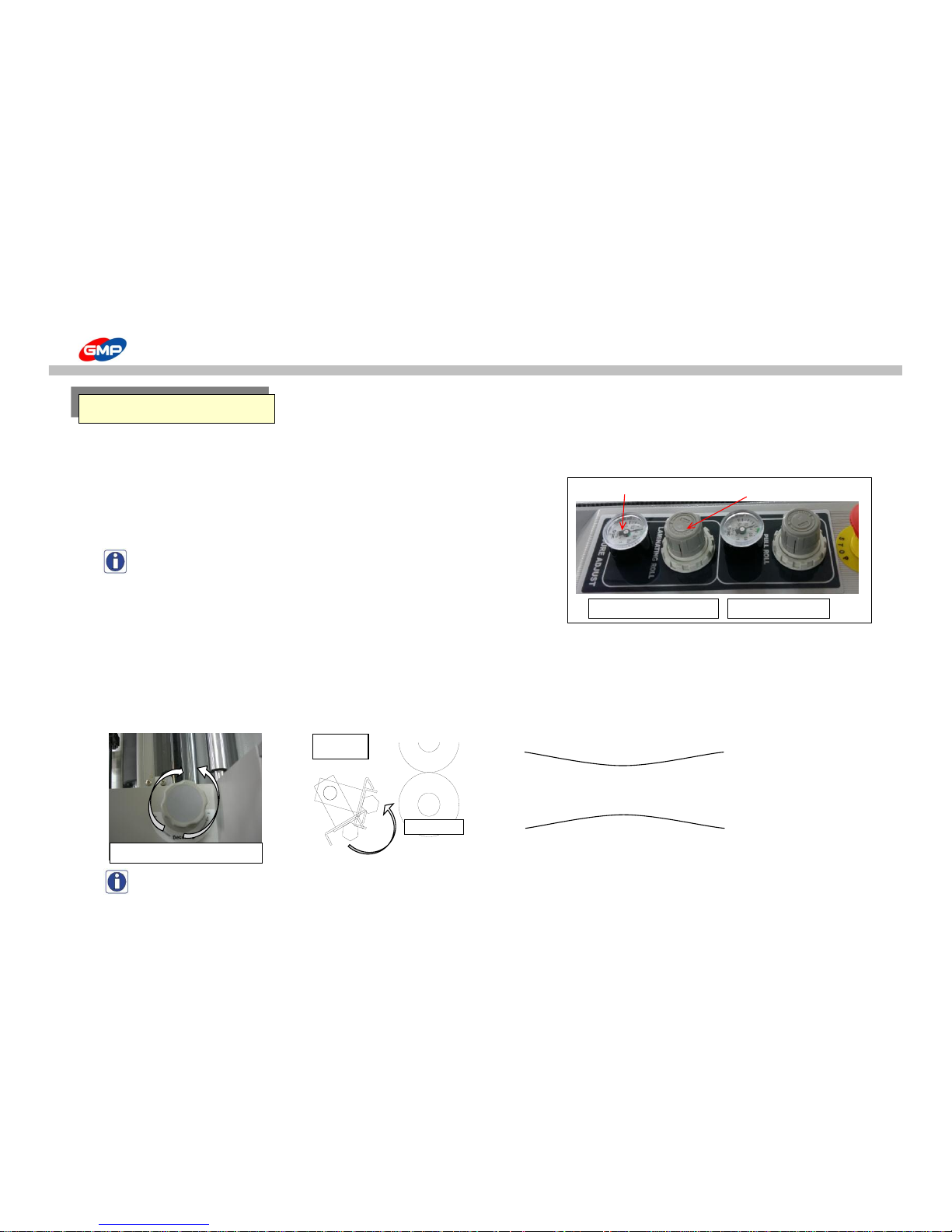
How to use the Main Devices
☞ How to adjust pressure on Laminating Roller
Pressure on Laminating Roller can be adjusted by Pressure Controller and its pressure is displayed on the pressure gauge.
Pull the controller to adjust pressure level and press it after adjustment is done.
Turn the knob to the right to increase its roller pressure and
Turn it to the left to decrease its pressure.
NOTE : Films / Substrates conditions requires adjustment of the roller pressure.
Max. Pressure is less than 0.6MPa(6㎏/㎠).
☞ How to adjust Decurling Value
It is natural thing to have the curled laminated results after lamination.
This is not caused by the trouble in the Laminator.
Decurling Device is to avoid the Curling on the Laminated Results after single side lamination.
Adjust the Decurling Status with the Handle as the Pictures.
Rotate the Handle to the Right to increase the Decurling Value and rotate it to the left to decrease it.
Curling Way for Left Direction Rotating of Handle
Curling Way for Right Direction Rotating of Handle
NOTE : Adjust the Decurler Angle for Substrates Thickness and its Materials.
Lamination Area
Decurling Adjustment Knob
Decurler
Pull Roller
Laminating Roller
pressure gauge
Pull Roller Pressure
Pressure Adjustment Knob
37/66
Page 38
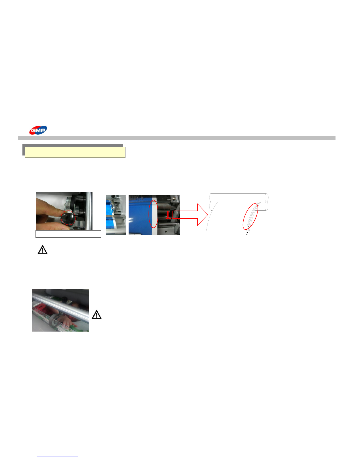
How to use the Main Devices
☞ How to adjust Perforator
To make holes at the edge lines of films for easy cutting of laminated results.
Place the perforator at 1~3mm from film edge.
Adjust its height to make holes on the films clearly.
WARNING : For initial loading or for moving of perforator, loosen the height adjustment knob.
Otherwise, this could be a cause of damage on perforator or on roller.
☞ Skewing Wheel
To make laminated results cut easily and clearly.
As the right picture, install the wheel to make sheet curve. This is to delay the laminated results exit to increase of cutting quality.
Wheel angle has to be adjusted to prevent laminated result fold.
WARNING : If Skewing Wheel would not be installed properly, the laminated results could be folded.
Cutting Area
Perforator Height Adjustment Knob
38/66
Page 39
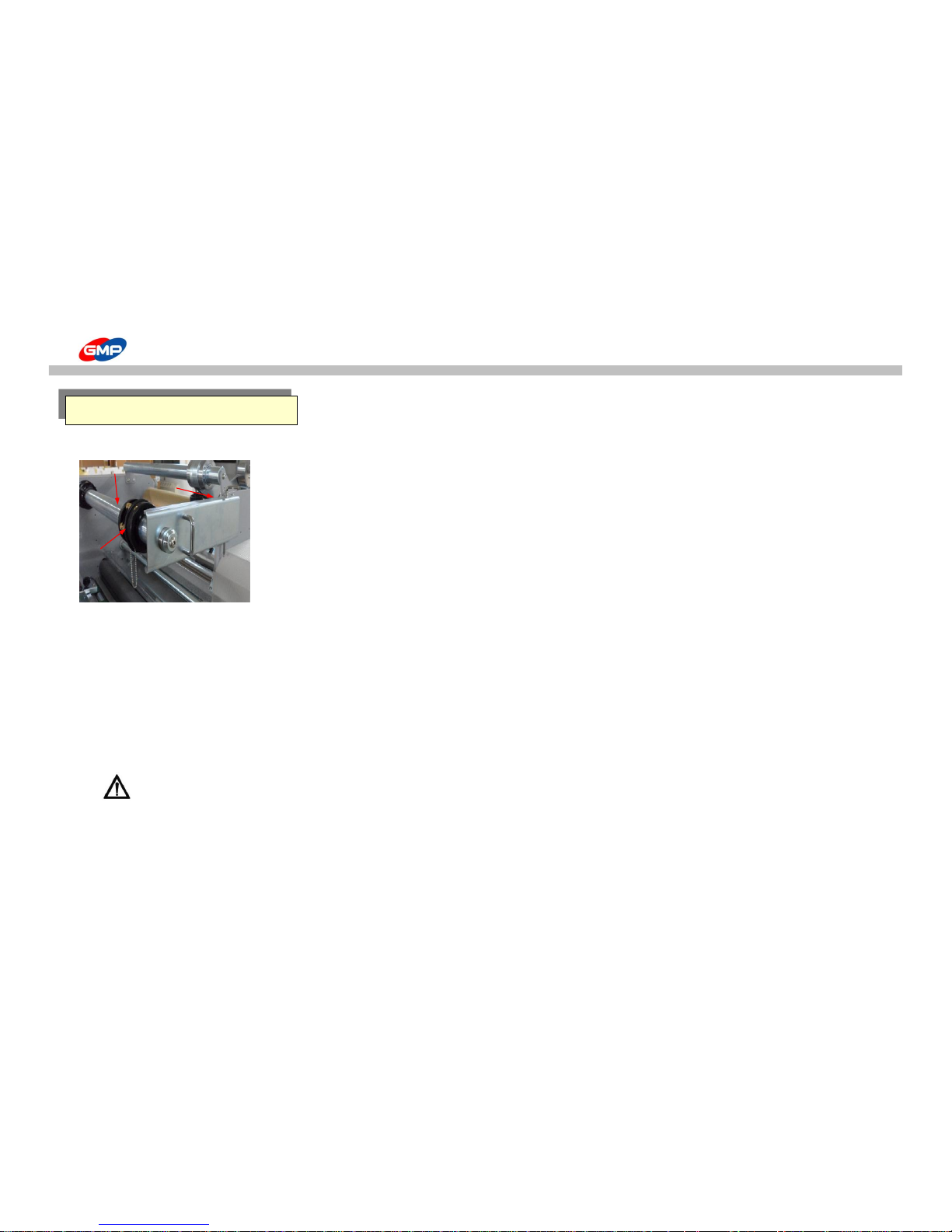
How to use the Main Devices
☞ Structure of Film Shaft
1. Film Shaft : To load the Laminating Roll Film.
2. Film Shaft Holder Fixing Pin : To avoid the movement of Film Shaft Support
3. Film Shaft Holder : To fix the Film Shaft to avoid movement of Film Shaft
4. Film Core : To fix the Laminating Roll Film
☞Film Loading
Film width has to be smaller than the Substrate's by 5~10mm.
1. Remove the Film Shaft Holder Fixing Pin.
2. Pull the Film Shaft Holder.
3. Load / Remove the Film Roll to / from the Film Shaft.
- Pull the Film Fixing Ring out from the Film Core and Load the Film Roll.
- After adjustment of film position, tighten up the Film Core Fixing Bolt.(Use the 5mm Wrench that is packed in the machine.)
4. Close the Film Shaft Holder and fix it with Fixing Pin.
WARNING : Film Roll is heavy, then more than 2 persons are required for film roll loading. Otherwise, this could be a cause of injury.
Loading of Laminating Films
②
①
③
④
39/66
Page 40
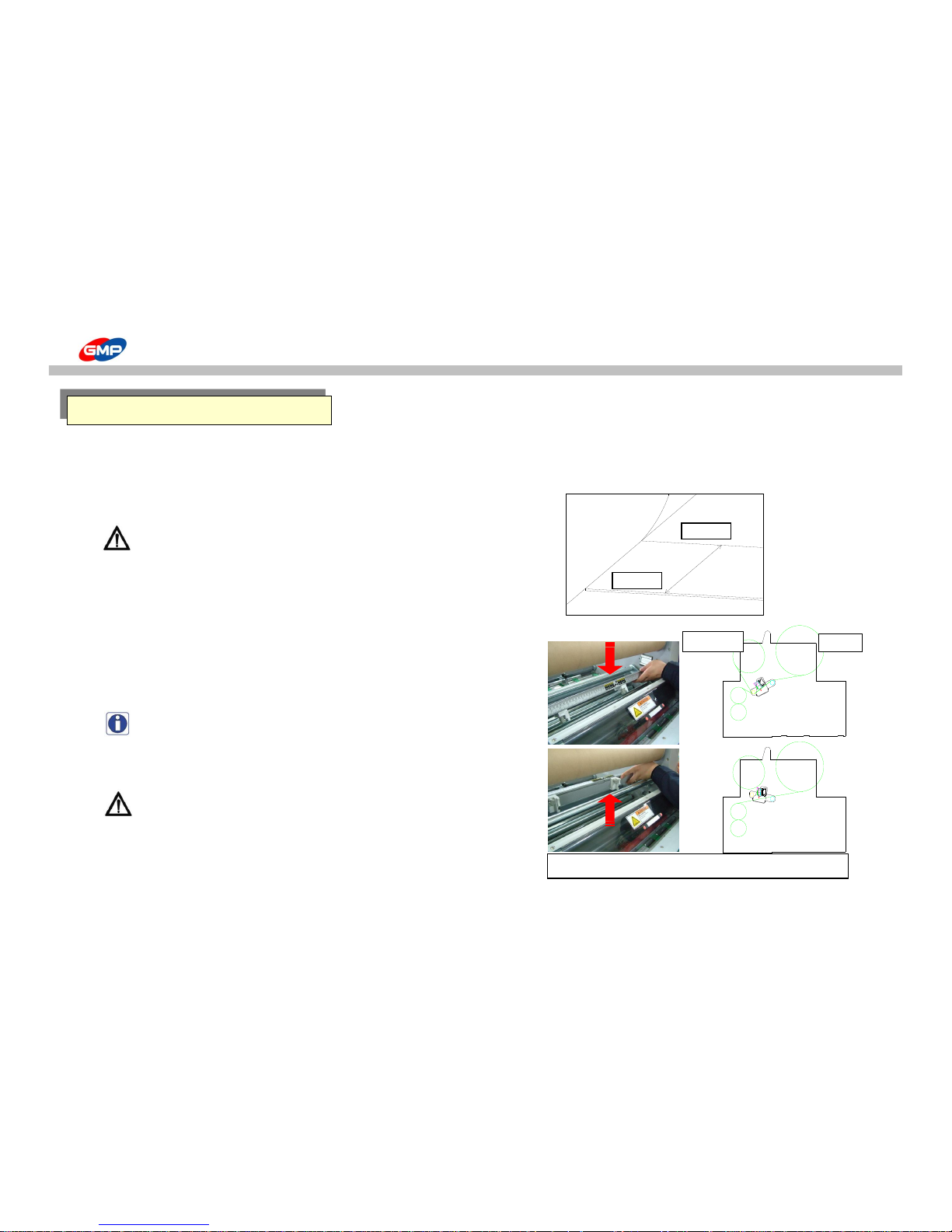
How to use the Main Devices
☞ Film Position
In accordance with Single Side Lamination condition, the substrate width has to be wider than the film width by 5~10mm.
Otherwise, the roller can be contaminated / damaged by glue on the Film.
Position the Film at the inside of the substrate end by 3~5mm as the below picture.
WARNING : Film width has to be smaller than the substrate width by 5~10mm.
Otherwise, this could be a cause of trouble / error.
☞ SIDE SLITTER & REWINDER
To slit the film width if the film roll width is wider than the substrate's one.
Position the Side Slitters as the right pictures and slit it.
Rewind the Slitted films at the Rewinder.
NOTE : This device has Up/Down Moving Structure for easy film loading.
WARNING : Blade is very sharp. Be careful for installation.
This could be a cause of injury.
Loading of Laminating Films
Substrate
Film
5mm
Film
Rewinder
Slit film with Side Slitters & Rewinder
40/66
Page 41
How to use the Main Devices
☞ Main Power Switch
Power Switch is to supply or to cut the Power to the Machine.
Press the Switch to the "I" direction, the Power is ON and to the "O" direction to Power OFF.
Power Switch has Circuit Breaker to cut the power supply for overload or over current status in the machine.
NOTE : If it would be occurred for more than 2 times continuously, please ask to the supplier.
☞ Tray Table
The Tray Table is useful for easy arrangement of Laminated Results.
Adjust the Guides on the Table for Substrates' width & length.
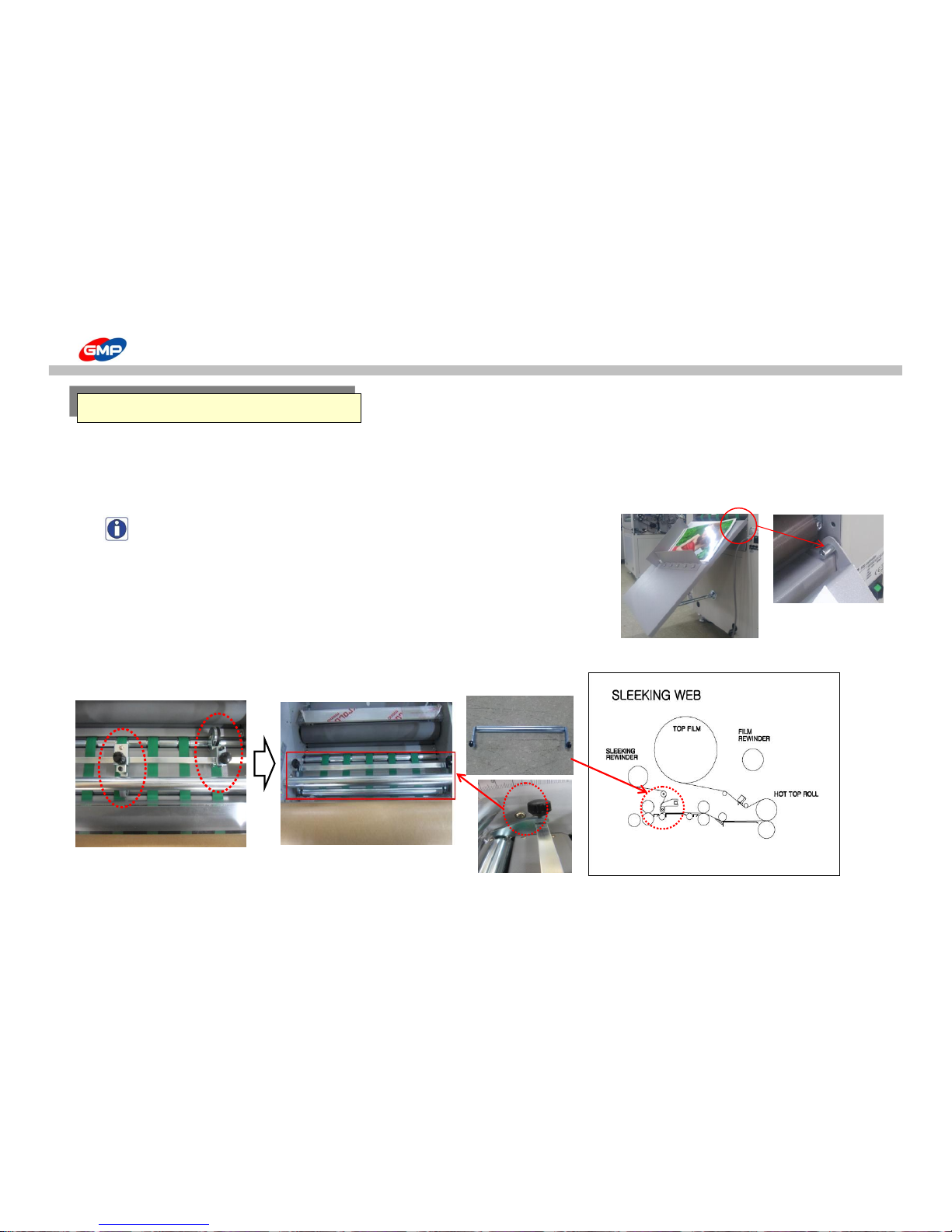
☞ Sleeking Idle Bar Installation
This is for sleeking operation to display gloss/matt, hologram, gold/silver foil in various effect.
The method of installation of Idle Bar & film for Sleeking is as below.
The Other Devices
1. removing perforator & Skewing
Wheel
2. install idle bar for sleeking
Sleeking Idle Bar
41/66
Page 42
How to Laminate
☞ Preparation for Lamination
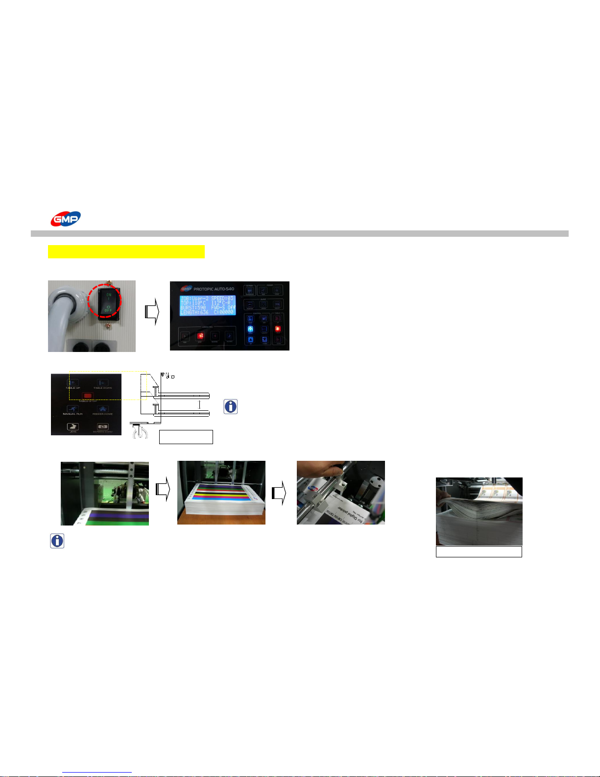
◐ Pile up substrates
1. Turn on the machine and the system is operated.
2. As the picture <1_1>, press "FEEDER TABLE UP/DOWN" on control panel to position the feeding table at the proper height.
NOTE : If the feeder would not be at the origin point,
the feeding table would not be moved upward.
Press "FEEDER HOME" on the control panel to position the Feeder at Origin Point.
3. Adjust Substrate Guide for substrate width and pile up substrates on feeding table.
NOTE : For stacking of substrates, as the picture<1_2>, make air layer in-between the sheets.
This is to prevent substrates stick each other and to prevent feeding error by static.
Stacking status is very important to minimize feeding error.
Picture <1_2>
Picture <1_1>
42/66
Page 43
How to Laminate
NOTE : If stacking height is different due to deformed substrate, make it level with wedge type wooden piece.
If an height is not leveled, this is the cause of feeding error.
- Do not recommend to use the below conditioned substrate.
This will bring feeding error or creasing on laminated results.
1. Corner or Cut area is curled or creased.
2. Substrate that is sensitive for heat.
3. Curled by humidity
4. Press "FEEDER TABLE UP" on control panel to move feeding table upward at feeder.
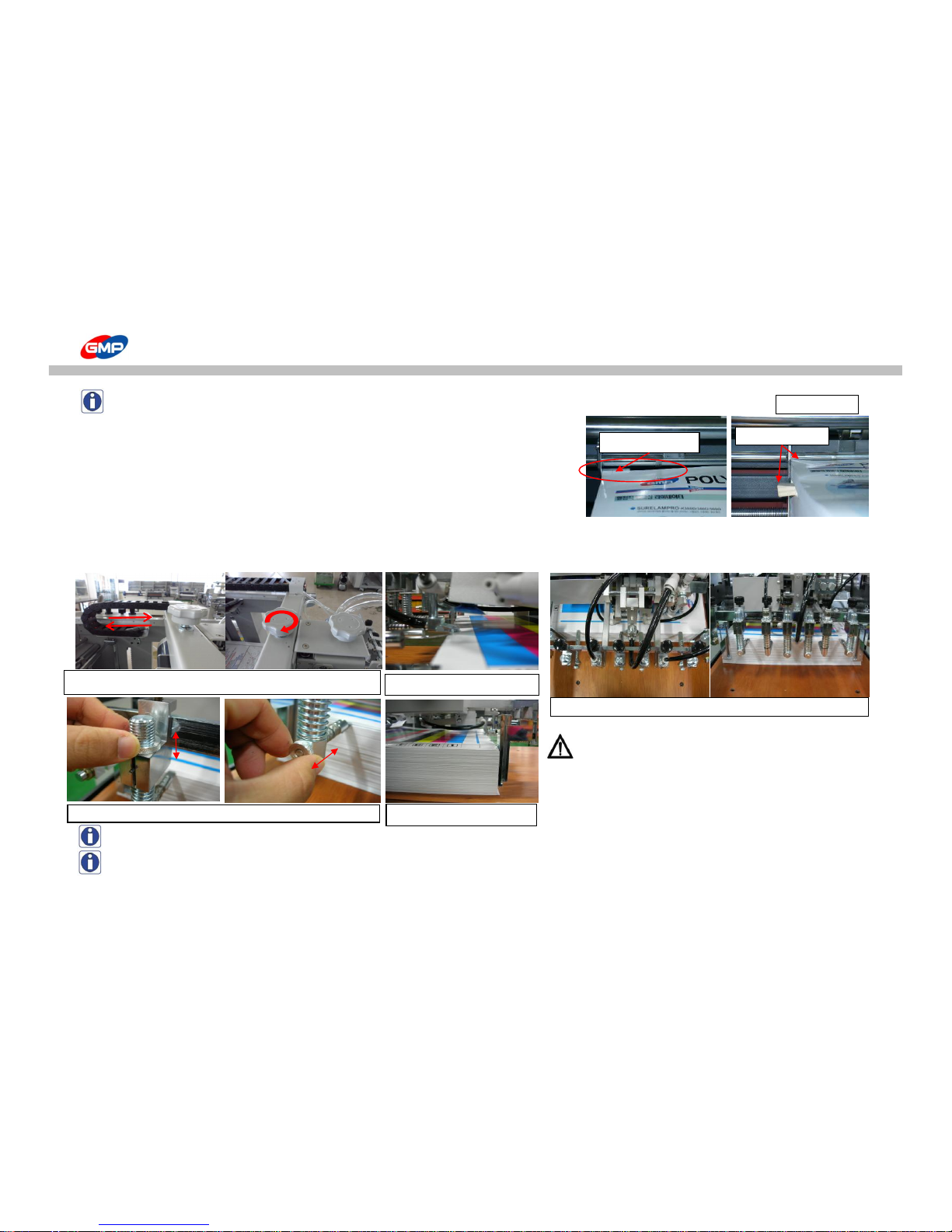
◐ Set up for Feeder
1. Position the feeder as the below pictures.
WARNING : After feeder is positioned, turn the fixing knob
to the right to fix it.
If the feeder is not fixed and it would be operated,
this is a cause of damage on the feeder.
NOTE : SEPARATOR is composed of thin metal plate, then if high pressure on it, the part could be damaged.
NOTE : If the REAR GUIDE would be stuck to substrate, this could be a cause of feeding error.
Position of REAR GUIDE
Height Difference
Height Adjustment
Picture <1_3>
Set-up for Feeder
Position of SEPARATOR : Knob for adjust position (front / rear)
Position of BLAST FOOT
Adjust position with substrate length and fix the feeder.
43/66
Page 44
How to Laminate
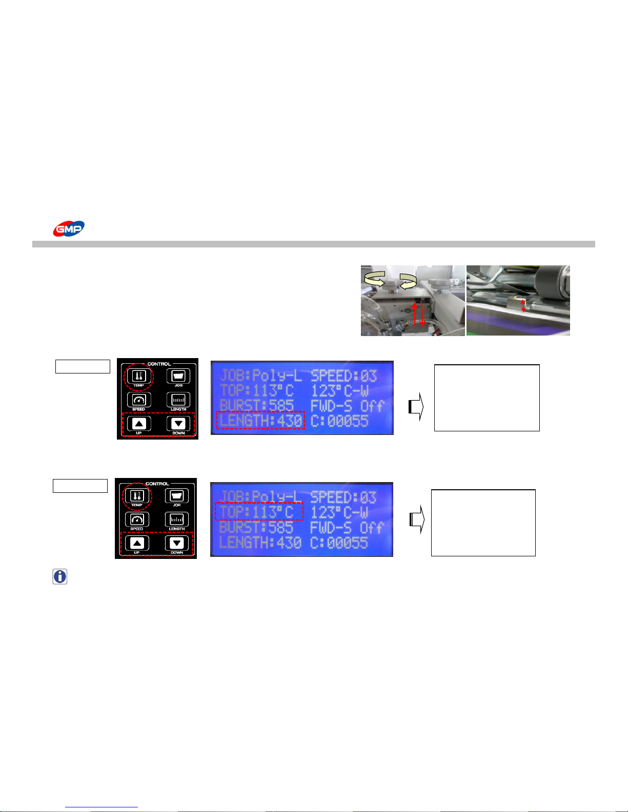
2. To set up the feeder, adjust height distance between substrates top and shutter
by 3~5mm.
If substrate top height is too higher than the shutter, this will make 2~3 sheets
to feed and if it is too lower than the shutter, this will make feeding error.
◐ Set up for Control Panel
1. As the picture<1_4>, press the "PAPER LENGTH" on control panel and set up the length of substrate with UP/DOWN buttons.
2. As the picture <1_5>, set up a required temp for laminating roller.
Press "TEMP" on control panel and set up temp. with UP/DOWN buttons.
NOTE : Basically, set temperature for POLYNEX FILM is 100~115℃, for NYLONEX(PERFEX)FILM is 110~130℃.
3~5mm
Substrate length is on display.
Put a required length.
Temperature is on display.
Put a required temperature.
Picture <1_4>
Picture <1_5>
44/66
Page 45
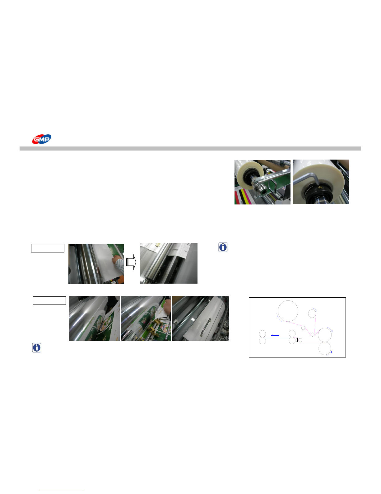
How to Laminate
◐ How to load film
1. Insert a film roll into the film shaft. Then, place the film shaft holder and insert the fixing pin.
Procedure
1) Remove the Film Shaft Holder Fixing Pin.
2) Pull the Film Shaft Holder.
3) Insert or Remove film roll into or from Film Shaft.
- Insert a film roll into the film shaft after the holder fixing pin is removed.
- Tighten the Film core fixing bolt after film is loaded. (Use the 5mm wrench in the packing.)
Use 5~10mm short width films than substrate.
If the film width would be wider than substrate, this could be a cause of contamination on roller / of cutting error.
2. Insert a substrate for loading from the laminating roller till the pull roller.
NOTE : substrate must be passed the decurler.
3. As the adhesive on film is melted, stick a substrate on the adhesive side of film and install the safety cover as the picture <1_7>.
NOTE : Refer to the right picture of web diagram.
4. Ready for Lamination.
Substrate
Loading Direction
Film Roll
Picture <1_6>
Picture <1_7>
45/66
Page 46
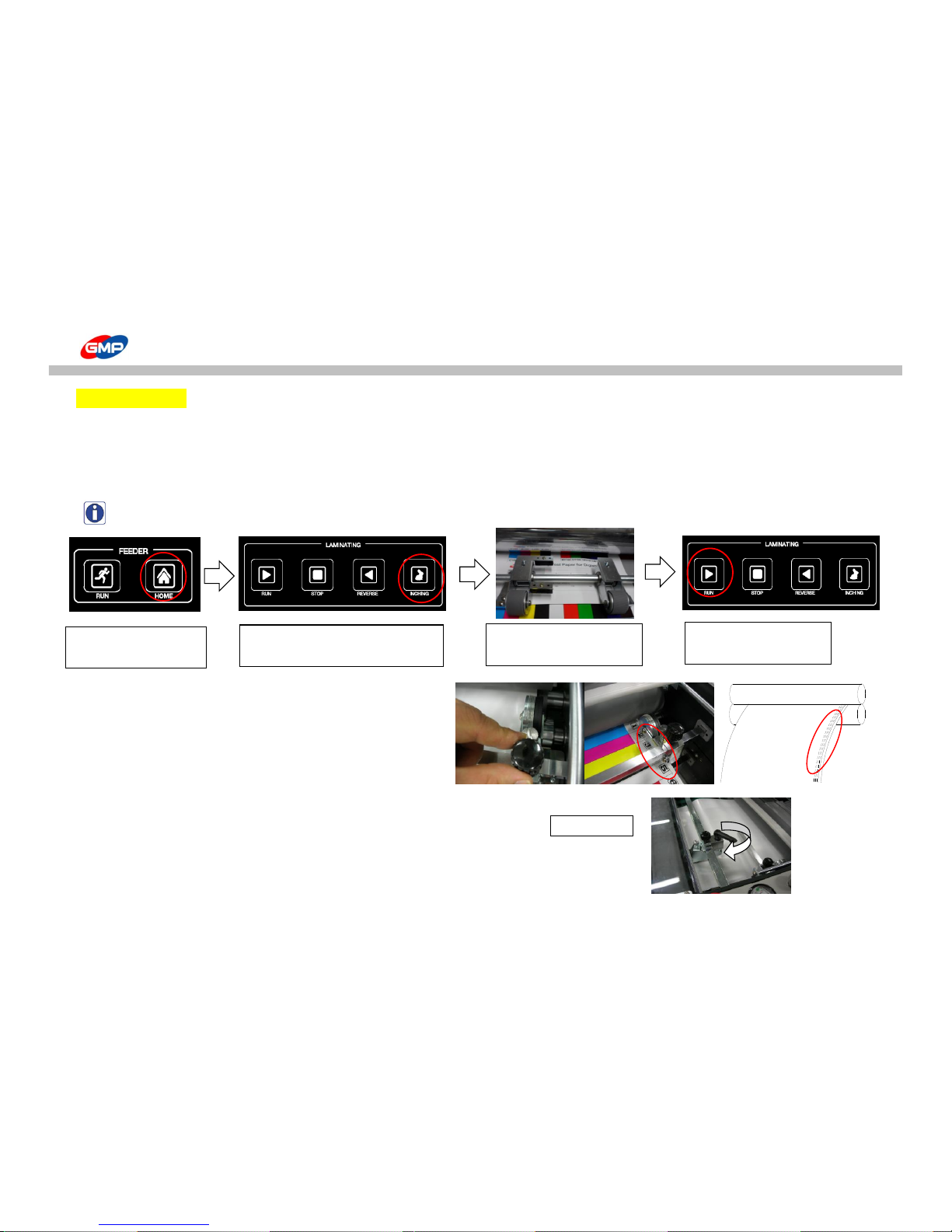
How to Laminate
☞ Lamination
◐ Test Lamination
1. When temp. on laminating roller is reached to setting temp., test lamination is required to check setting status & laminating quality.
Press "RUN" to make roller engage and lamination is processed.
Feeding gap & Feeding error has to be checked for the 1st 3~4 sheets feeding.
For test lamination, the lower speed (3~5m/min) is recommended. Then, its test result is good, increase its speed.
NOTE : How to load substrate after release from E-Stop status. (ex: EMERGENCY, Safety Cover is opened.)
2. If there is no problem for substrate feeding, set up the perforator.
Position the perforator at 1~3mm from film edge.
If the perforator would be more inside of the above position,
this could be a cause of quality trouble & cutting error.
Pressure on film to make holes clearly.
3. Press "BURSTING" on "MAIN" screen to activate Burst "ON" status.
Rotating Bursting roller is moved up/down to cut the laminated results.
If a cutting quality is not good, install the skewing wheel as the picture <2_2>.
Picture <2_2>
① Feeder at Origin Point.
② Move sheets at Feeding Wheel to
Laminating Roller in Job Mode.
③ Attach the substrate end to
the film on roller.
④ Press Run Botton.
46/66
Page 47

How to Laminate
※ Checking Points for Test Operation
1) Overlapped distance : Ideally, 3~5mm.
If overlapped distance is too short, press "PAPER LENGTH" on "MAIN" mode of Control Panel
to reduce setting value of substrate length.
2) Curling on Substrate : Check the curling status of substrate and adjust curling with decurler.
It is natural thing to have curled laminated results for single side lamination. Then, this is not caused by a trouble in laminator.
Curling Way for Right Direction Rotating of Handle
Curling Way for Left Direction Rotating of Handle
Adjust the Decurler Angle for Substrates Thickness and its Materials.
3) Laminating Status : Check the status with variation of setting temp. speed and pressure.
Each conditions has to be adjusted for film / substrate status.
Quality of Adhesion is proportional to temp. and pressure and is inversely proportional to speed.
4) Cutting Status : Check operation time for bursting roller and Perforator setting status.
◐ LAMINATION
If the test lamination has a good results, increase its speed for lamination.
NOTES
1. Stop while lamination job could make mark on the laminated results.
2. Basically, the thicker substrate requires the further slower speed and the higher temp.
3. Basically, the thinner substrate requires the further faster speed and the lower temp.
4. If it requires to have the exact lamination condition but no / rare test materials, set conditions with the similar materials firstly.
after on, check its required estimated conditions to the lamination.
5. If a sheet would not be fed into the feeder, this will be a cause of wrinkle on the laminated results.
47/66
Page 48
Maintenance
※ If the roller would not be cleaned;
- Film could be stuck & wound on the roller.
- The laminated results could be contaminated.
※ How to Clean
- After lamination job is done, when the laminating roller temp. is lower than 80℃, clean the roller with "cotton" & "Isopropyl alcohol".
WARNING : Isopropyl alcohol is required to clean the rollers.
WARNING : Laminating Roller temp. is too high, then if a part of body would be contacted, this could be a cause of burn.
※ To clean the body of the machine
- Smooth and dried cloth is required to clean the body of the machine.
WARNING : Unplugged status is required. Otherwise, this could be a cause of fire.
WARNING : 아 Do not use a volatile such as, Acetone, Benzene, Thinner. This could be a cause of fire.
Clean the Roller
Clean the Machine
48/66
Page 49
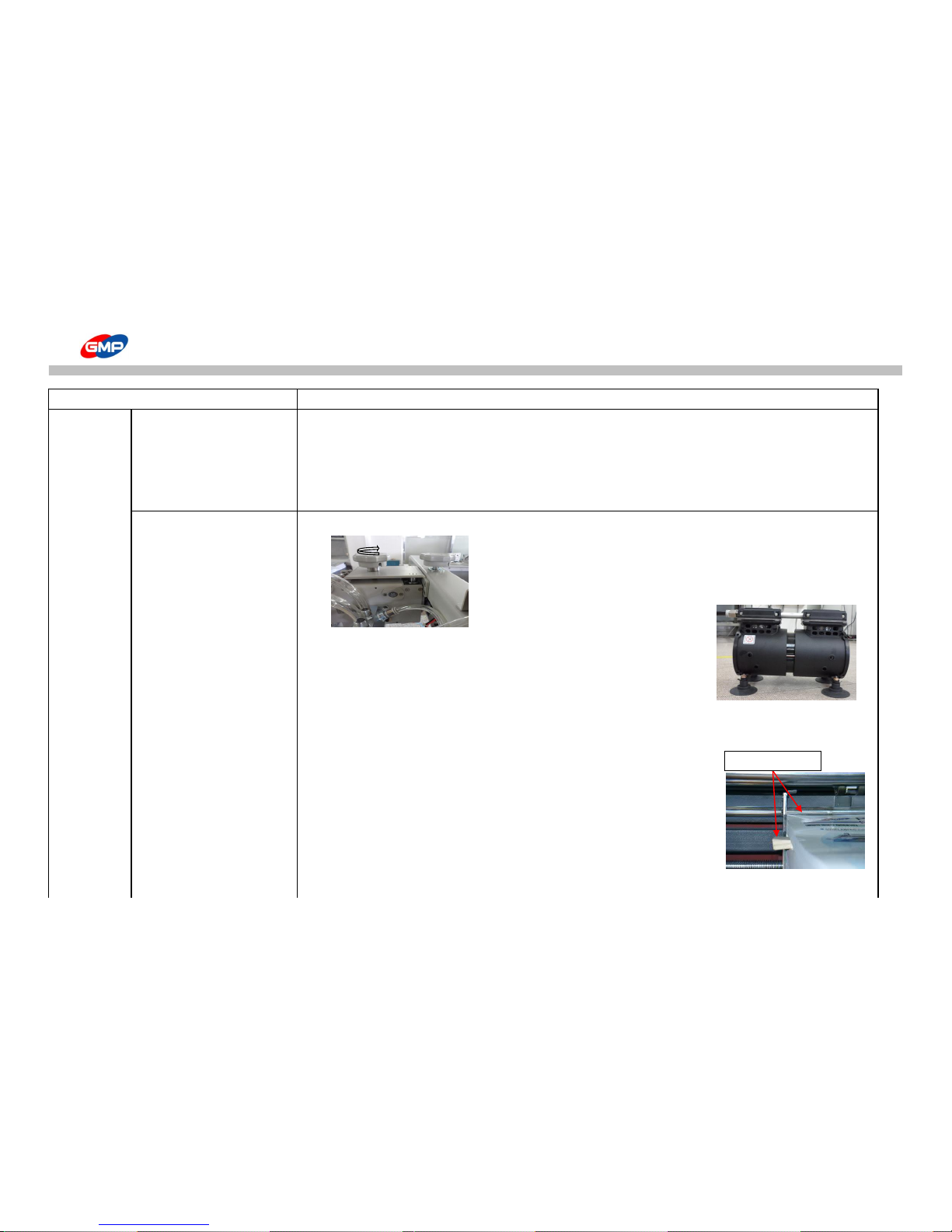
TROUBLESHOOTING
Symptoms Cause of Trouble & Troubleshooting
Feeding Area Feeding Table is not moved 1. If the feeder is not at origin point,
upward. -> Press "FEEDER HOME" to make the feeder at origin point.
2. If Emergency Stop is activated,
-> E-stop status is released, the system is operated in normal.
Process the above No. 1.
Substrates are not fed. 1. Position of PICK UP CUP is too far from substrate.
-> As the left picture, rotate the feeder height adjustment knob to the right
to move upward the feeder and move the feeding table upward.
Recommendable distance between pick up cup and
substrate top is 20mm.
2. If vacuum pump is defective.
-> Replace the vacuum pump. Contact to a supplier.
3. Phase of Input Voltage of Vacuum Pump is reversed and pump is operated reversely,
-> Make the phase back to normal. Stop operation and contact to a supplier.
4. If substrate is curled downward too much,
-> As the right picture, make substrate in same level with wedge type
wooden piece.
5. If pressure for separator at Feeder is too high or pressed area is too big.
6. Rear Guide is too close to substrates.
7. Air amount from BLAST FOOT is small.
Height Adjustment
49/66
Page 50
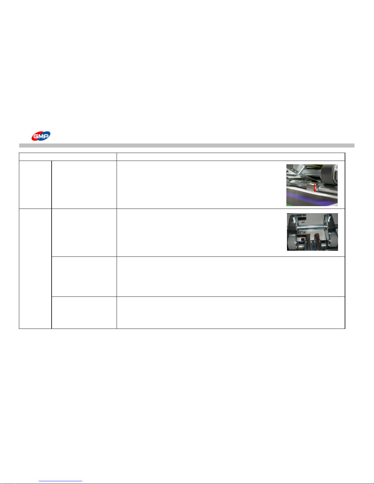
TROUBLESHOOTING
Symptoms Cause of Trouble & Troubleshooting
More than 2 sheets are fed 1. Separator is at wrong position.
-> Recommend area of plate of separator to substrate is 5~7mm.
2. Distance between top end of Shutter and substrate top is less than 3mm.
or substrate top is higher than shutter height.
-> Rotate the feeder height adjustment knob to the left to reduce its height.
For this status, move the feeding table downward firstly and move it upward.
Substrates are not fed straight 1. Left/Right pressure of feeding wheel is not same each other.
-> Reduce pressure of feeding wheel that makes wrong direction of sheet.
2. Left/Right pressure on Laminating roller is not same each other.
-> Contact to a supplier.
Feeding sheets distance are not same.
1. Substrate Alignment Cylinder is defective.
-> Replace its cylinder. Contact to a supplier.
-> Solenoid Valve is defective. Check connection status of signal cable.
Replace Solenoid Valve. Contact to a supplier.
2. Main Belt tension is loosen.-> Contact to a supplier.
Operation is stopped. 1. If substrates has gap due to feeding error, system is stopped.
-> Press "FEEDER HOME" button to make feeder at origin point.
2. E-stop S/W is activated.
-> Release it from E-Stop status.
3~5mm
50/66
Page 51
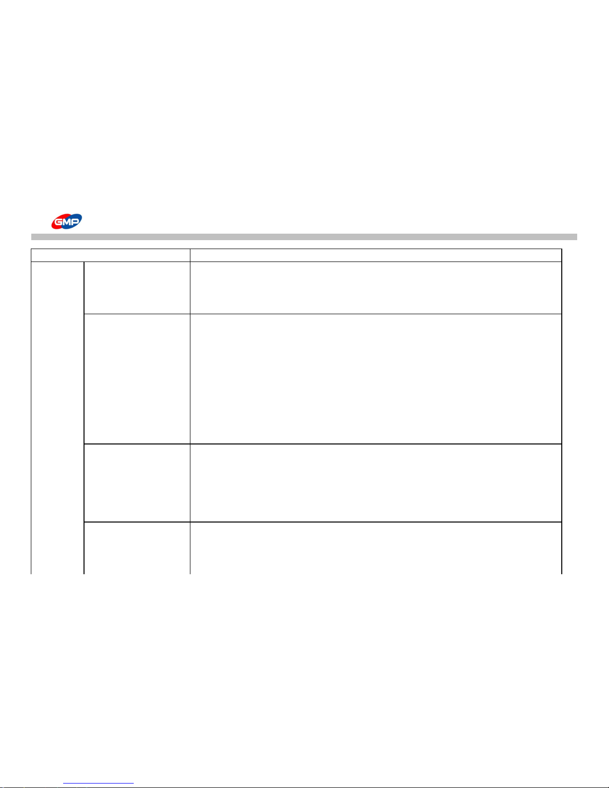
TROUBLESHOOTING
Symptoms Cause of Trouble & Troubleshooting
Lamination Laminating Roller is not 1. If safety switch at roller cover is opened. -> Close the roller cover safety switch.
Area operated. 2. This could be caused by motor for laminating roller or chain is defective.
-> Contact to a supplier.
3. Fuse blows -> Replace it with 250V/12.5A that is packed with machine.
If Laminating roller is not heat up
1. Temp setting is not processed on Control Panel. -> Contact to a supplier.
or temp. is not increased 2. Power supply for laminating roller is defective. -> Contact to a supplier.
from a certain one. 3. If temp. sensor is defective.
-> Remove foreign materials.
4. Foreign materials are between temp. sensor & roller.
-> Remove foreign materials.
5. If heater is defective. -> Contact to a supplier.
6. If THERMOSTAT is activated.
-> Cool down the product and restart.
The same trouble would be occurred, contact to a supplier.
Adhesion is not good 1. Adhesion of lamination is proportional to the below conditions.
However, a proper adjustment will be required for laminated results.
-> Thicker substrates requires higher setting temp. and higher pressure.
-> Faster laminating speed requires higher setting temp. and higher pressure.
2. Embossing lamination requires lower speed, higher setting temp. and higher pressure.
3. Black / Dark Colored prints requires lower speed and higher pressure.
Film is cut while lamination 1. In-line sub perforator is applied.
-> Thinner film makes film cut more easily.
2. Laminating Roller temp. is high.
-> Adjust laminating roller temp. to reduce its temp.
51/66
Page 52
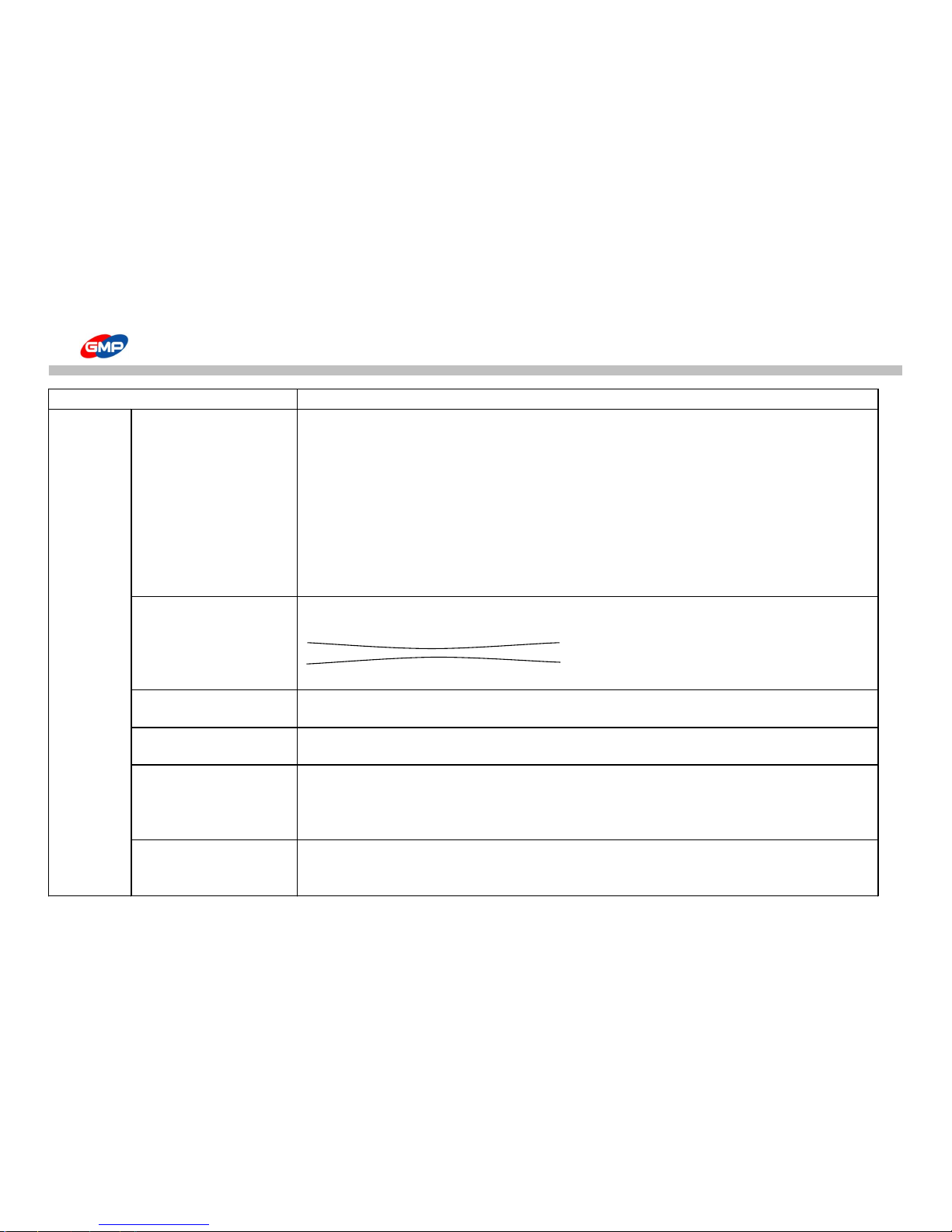
TROUBLESHOOTING
Symptoms Cause of Trouble & Troubleshooting
Wrinkles are on the laminated 1. Nip Roller is contaminated by film / substrate that is stuck on it. -> Clean the roller with cleaner.
results 2. Nip Roller is defective. (trouble in production, damaged surface, etc.)
-> Replace the roller. Contact to a supplier.
3. Laminating roller surface is contaminated by adhesive on films. -> Clean the roller with cleaner.
4. Left/Right pressure on Nip Roller is not same each other.
-> Adjust left/right pressures. Contact to a supplier.
5. Lamination for less than 120gsm substrate.
-> The thinner substrates are not recommended for lamination.
6. Laminating Roller Setting Temp. is high. -> Reduce laminating roller setting temp.
7. Substrate has high humidity. -> Place substrates in dried area.
Curling on laminated results 1. Wrong setting for Decurler.
-> Make a proper angle for the best decurling results with decurler knob.
Curling Way for Right Direction Rotating of Handle
Curling Way for Left Direction Rotating of Handle
2. Film tension is too high. -> Reduce its tension with Film Tension Adjustment Knob.
Film Shrinkage is too high
1. Film tension is too high. -> Reduce tension with film tension adjustment knob.
2. Laminating Roller temp. is too high. -> Reduce its setting temp.
Laminating Speed is not regular.
1. Chain tension is loosen. -> Need to adjust its tension. Contact to a supplier.
2. Several sheets are fed by feeding error.
Substrates are folded 1. Applied film has short width and margins on substrate is wider.
-> Recommend to use film that has shorter width than substrate by 5~10mm.
2. Under lapped area between the sheets is wide.
3. Angle for decurler is too high.
Rewinder is not rotated 1. Tension on rewinder is loosen.
-> Increase its tension with Rewinder Tension Adjustment Knob.
2. Chain is defective / damaged. -> Contact to a supplier.
52/66
Page 53
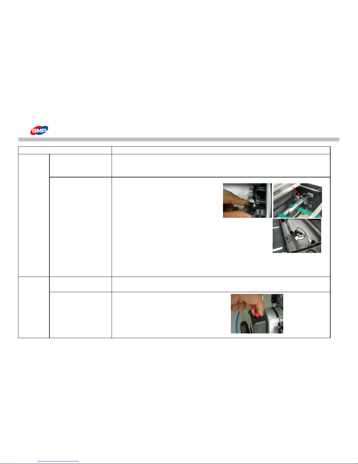
TROUBLESHOOTING
Symptoms Cause of Trouble & Troubleshooting
Cutting Area Bursting Roller is not 1. Defective Bursting Roller Motor or Chain -> Contact to a supplier.
operated. 2. Fuse blows -> Replace it with 250V/8A that is packed with machine.
3. Defective Air Compressor -> Contact to a supplier.
Cutting is not good 1. Perforator is at wrong position.
-> Place it at 1~3mm from film edge.
2. Perforator has lower pressure.
-> Increase pressure with pressure adjustment bolt.
3. Setting for skewing wheel is wrong.
-> Install the wheel to make sheet curve.
The wheel skews a lot the laminated results, the results are damaged
or it skews reversely, it makes cutting error.
4. "NYLONEX(Nylon base)","PERFEX(PET base)" films are used.
-> Characteristics of the above materials make cut hard. Increase angle for the skewing wheel.
-> Press "BURST SPEED" in "SET" mode to increase bursting roller rotating speed.
5. Use In-Line Perforator.
Others Machine is not turned on. 1. If the power plug is incorrect. -> Insert the plug into the outlet exactly.
2. Fuse blows -> Replace it with 250V/12.5A fuse
Air Compressor is not operated.
1. Cap is pressed.
(Optional) -> After connecting the power and pull the cap.
pressure adjustment
bolt
The direction of the
skewing wheel
53/66
Page 54
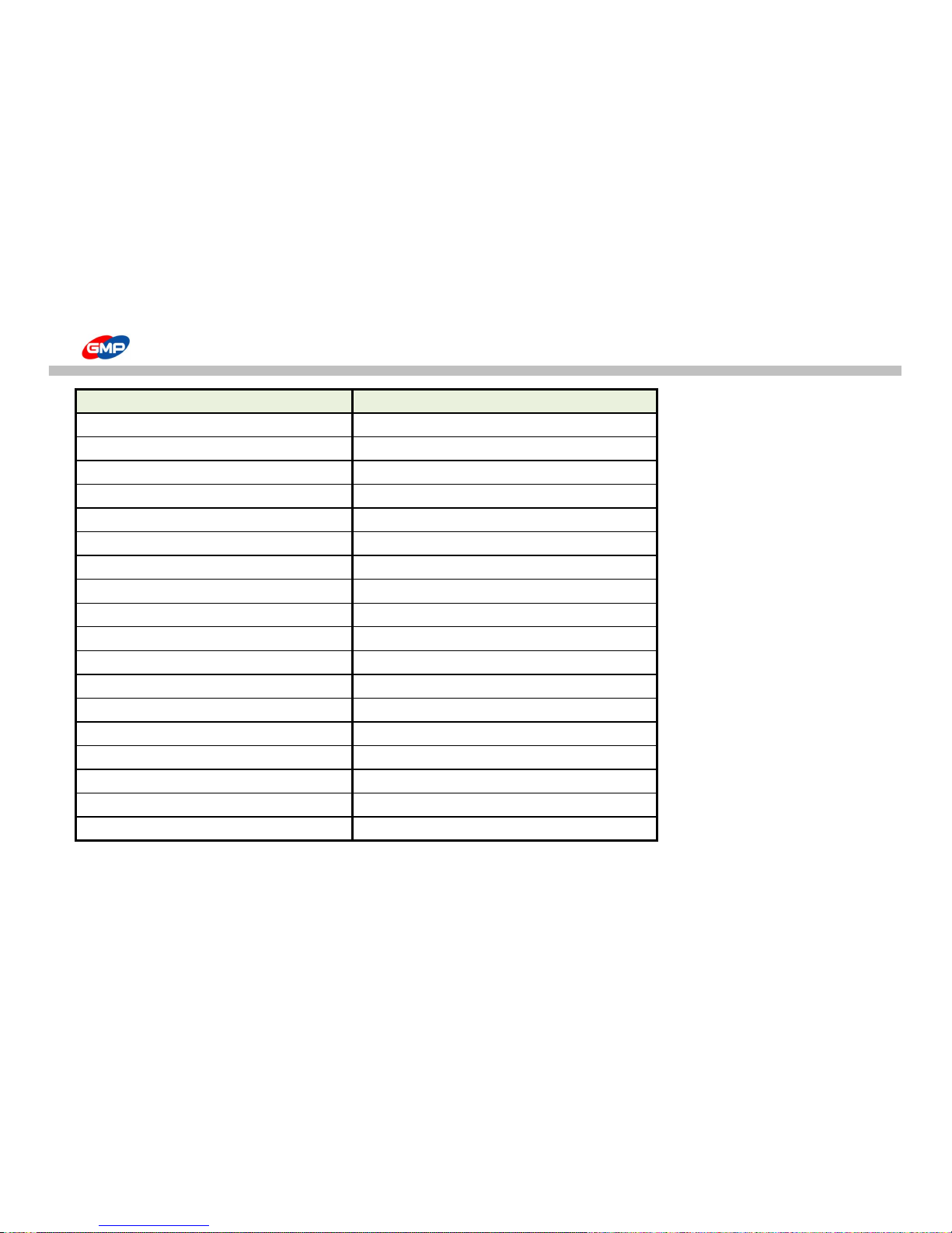
SPECIFICATION
Items PROTOPIC AUTO - 540 HS
Dimension (W*L*H)(mm) 800*1675*1320
Max. Laminating Speed(m/min) 25
Max. Substrate Size(W*L)(mm) 540*750
Min. Substrate Size(W*L)(mm) 210*254
Substrate Thickness Range(g/㎡)
120~350
Laminating Films
POLYNEX, PERFEX, NYLONEX FILM
Power Requirement
AC 380 ~ 400V / 21A
Power Consumption 5 kw
Warm-Up Time 7 minutes
Heating System
INFRARED HEATER
Roller Temperature (℃)
MAX. 150
Temperature Control
TOUCH KEYPAD
Speed Control
TOUCH KEYPAD
Bursting Motor
DC MOTOR
Roller Pressure Pneumatic Cylinder
Film Core 77MM(3")
Air Compressor 2Hp 19L
Vacuum Pump 250W 120LPM
※ External Design and Specification could be changed for improvement without prior notice.
54/66
Page 55
DIGITAL SLEEKING SOLUTION - Introduction
GMP DIGITAL SLEEKING SOLUTION is the epoch solution to provide various value-added products with Whole Page & Spot Gloss/Matt/Hologramming
with GMP Laminators.
1. SLEEKING (GLOSS & MATT FINISH)
SLEEKING FOIL : GLOSS SLEEKING FOIL, MATT SLEEKING FOIL
2.HOLOGRAM SLEEKING FOIL
① SPARKLE-HOLOGRAM ② HIPER PLAID-HOLOGRAM ③ CRYSTAL-HOLOGRAM ④ MILKY WAY-HOLOGRAM
⑤ STAR-HOLOGRAM ⑥ SPECTRUM-HOLOGRAM
3. METALLIC SLEEKING FOIL
① GOLD ② SILVER ③ METAL-BLUE ④ METAL-GREEN ⑤ METAL-RED
4.IMAGE TRANSFER
Transfer any kind of image can be transferred to any surface with GMP Transfer Media & GMP Laminators.
DIGITAL SLEEKING SOLUTION
55/66
Page 56
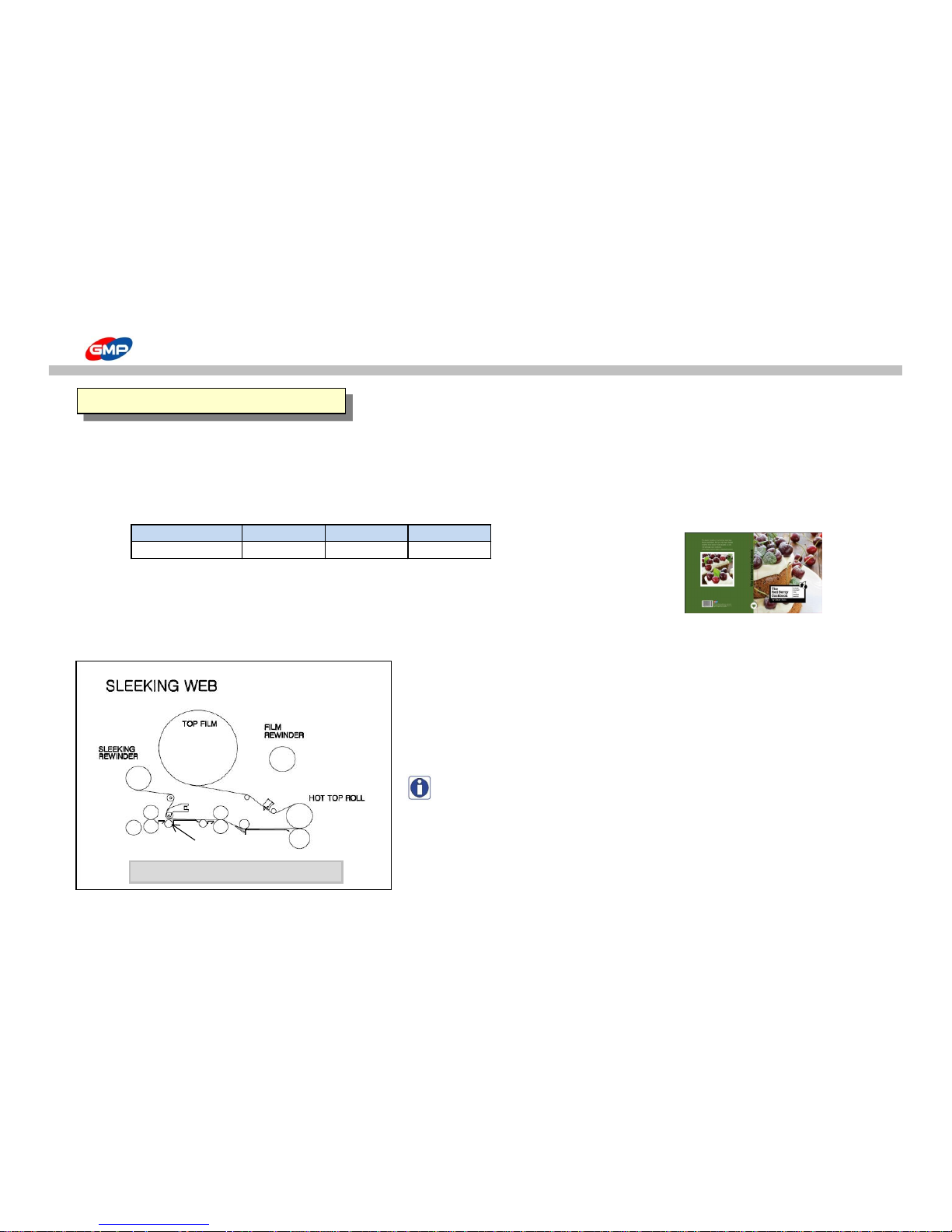
SLEEKING (GLOSS & MATT FINISH)
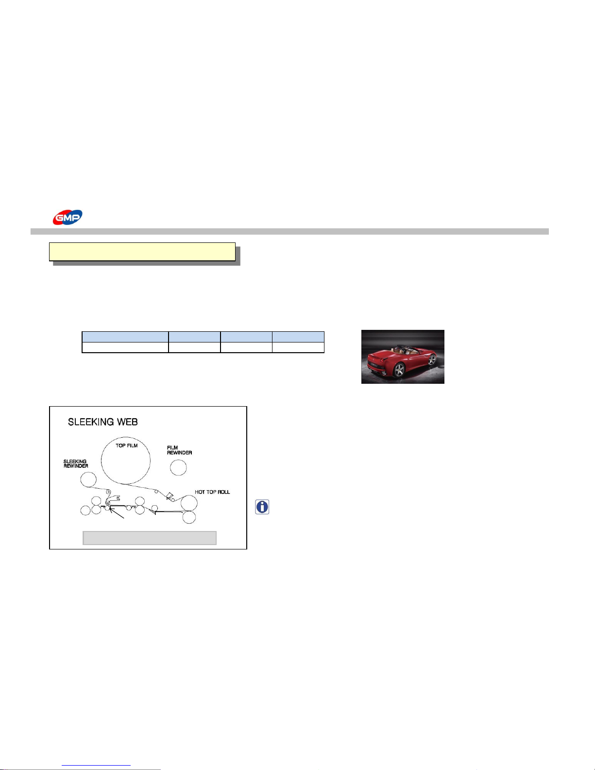
With GMP GLOSS SLEEKING FOIL & MATT SLEEKING FOIL, the surface of Toner Based Prints / Digital Prints can be
changed for higher quality of results.
Conditions for GLOSS/MATT SLEEKING FOILS
Model
Speed Set Temp.(℃) Pressure (MPa)
PROTOPIC III Series
3 110 0.5
(Table 1.1)
How to load the Foils
(Picture 1.1)
(Picture 1.2)
NOTE : This is for sleeking operation to display gloss/matt, hologram,
gold/silver foil in various effect.
The method of installation of Sleeking Idle Bar is as How to use
the Main Devices.
1.GLOSS/MATT SLEEKING
PROTOPIC AUTO- 540 HS
SLEEKING IDLE BAR
56/66
Page 57
SLEEKING (GLOSS & MATT FINISH)
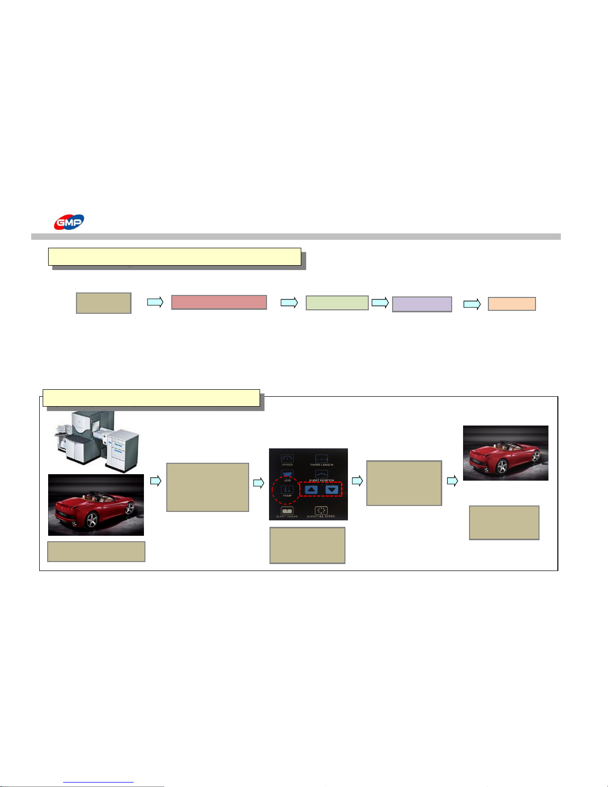
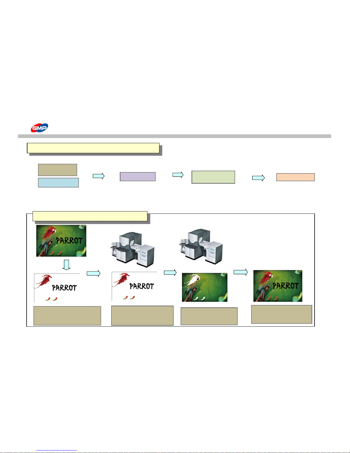
① Whole Page Gloss / Matt Sleeking
PRINTER FILM
HP INDIGO 3500 GLOSS SLEEKING FOIL
Refer to the Pic. 1.2
Temp. / Speed Setting
XEROX 5252 LAMINATOR
Refer to the Table 1.1
PROTOPIC III - 540
EUROLAM III - IDH 540
PIONEER - IDH5500PLUS
POD Prints
(DIGITAL PRINT)
FILM & LAMINATOR
Film Loading
SLEEKING
FINISH
2. Whole Page Gloss / Matt SLEEKING SOLUTION
1.Print Out POD Prints.
2. Sleeking on the
Printed Surface in
process of (Table 1.2)
3.Setting
- Roller
Temp. :110℃
- Speed:3
4. Put substrates on
the Feeder Table
and Press "RUN".
5.Whole surface
has Gloss Finish.
(Table.1.2) Whole Page Gloss/Matt Sleeking for Prints
57/66
Page 58
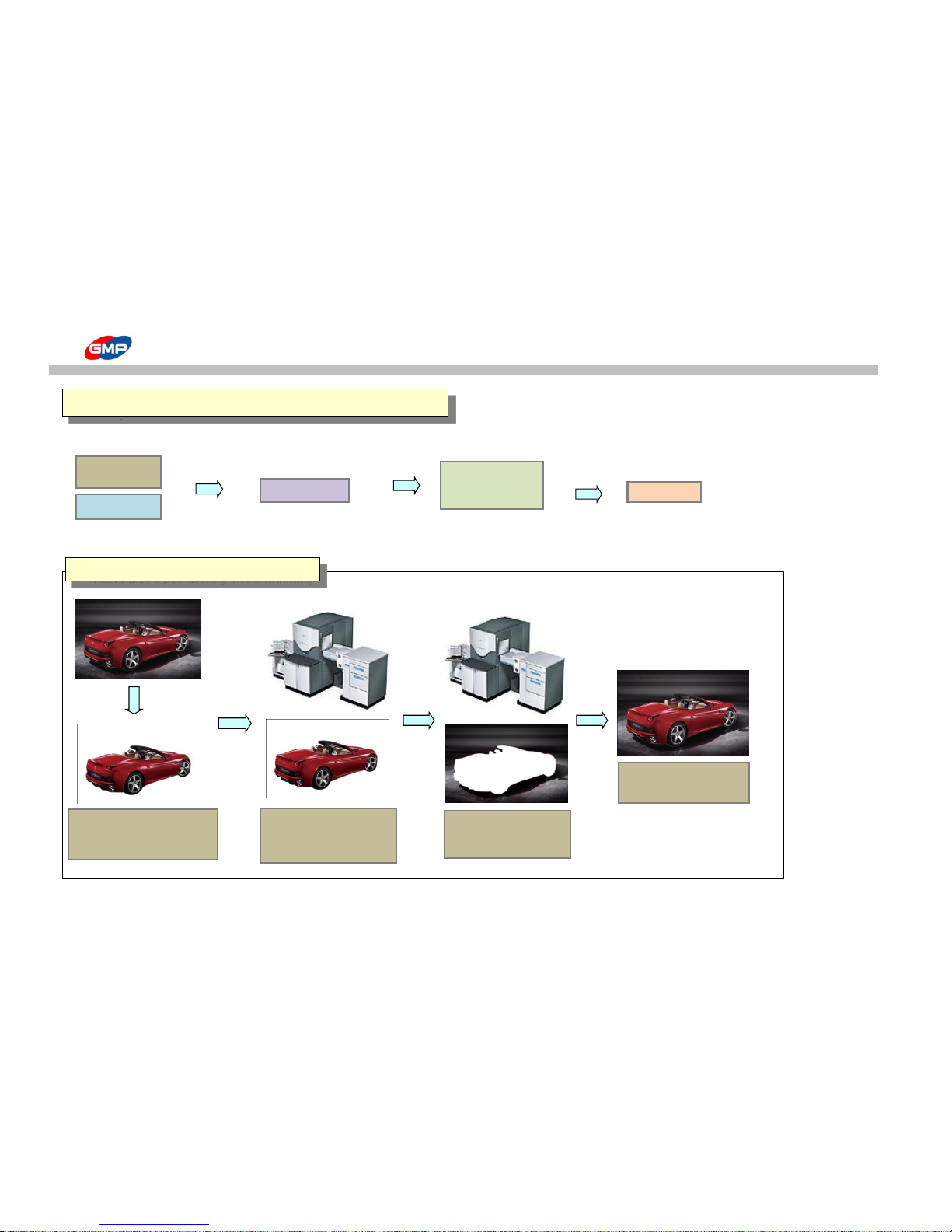
SLEEKING (GLOSS & MATT FINISH)
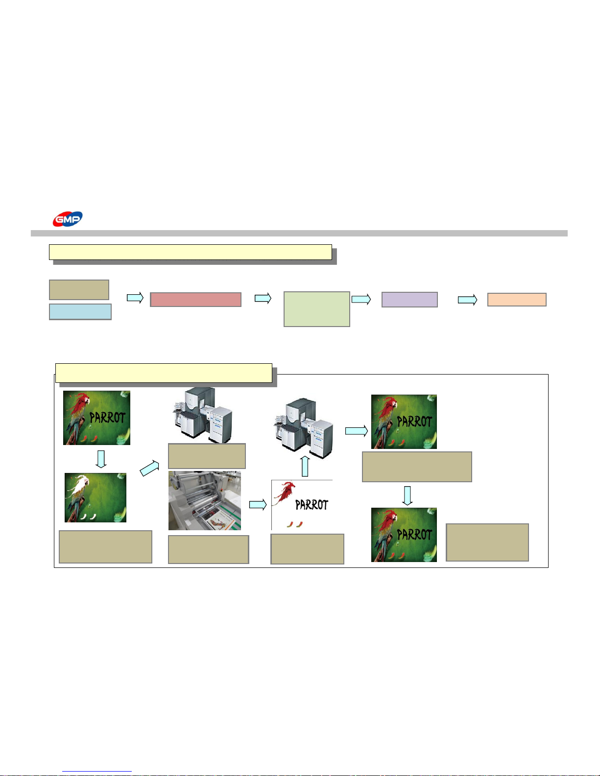
② Spot Gloss / Matt Sleeking
Temp. / Speed Setting
PRINTER
Refer to the Table 1.1
HP INDIGO 3500
XEROX 5252
POD Prints
(DIGITAL PRINT)
POD Prints
(DIGITAL PRINT)
SLEEKING
FINISH
OFFSET Prints
2. Spot Gloss/Matt SLEEKING SOLUTION with Prints
1.Cut the Car
Image(Picture 1.2) with
Image Editing Program
3. Print the
Background Image.
4. Only the Spot
Image has Sleeking
(Table 1.3) Spot Gloss / Matt Sleeking
2. Sleeking on the Printed
Surface in process of (Table
1.2)
58/66
Page 59
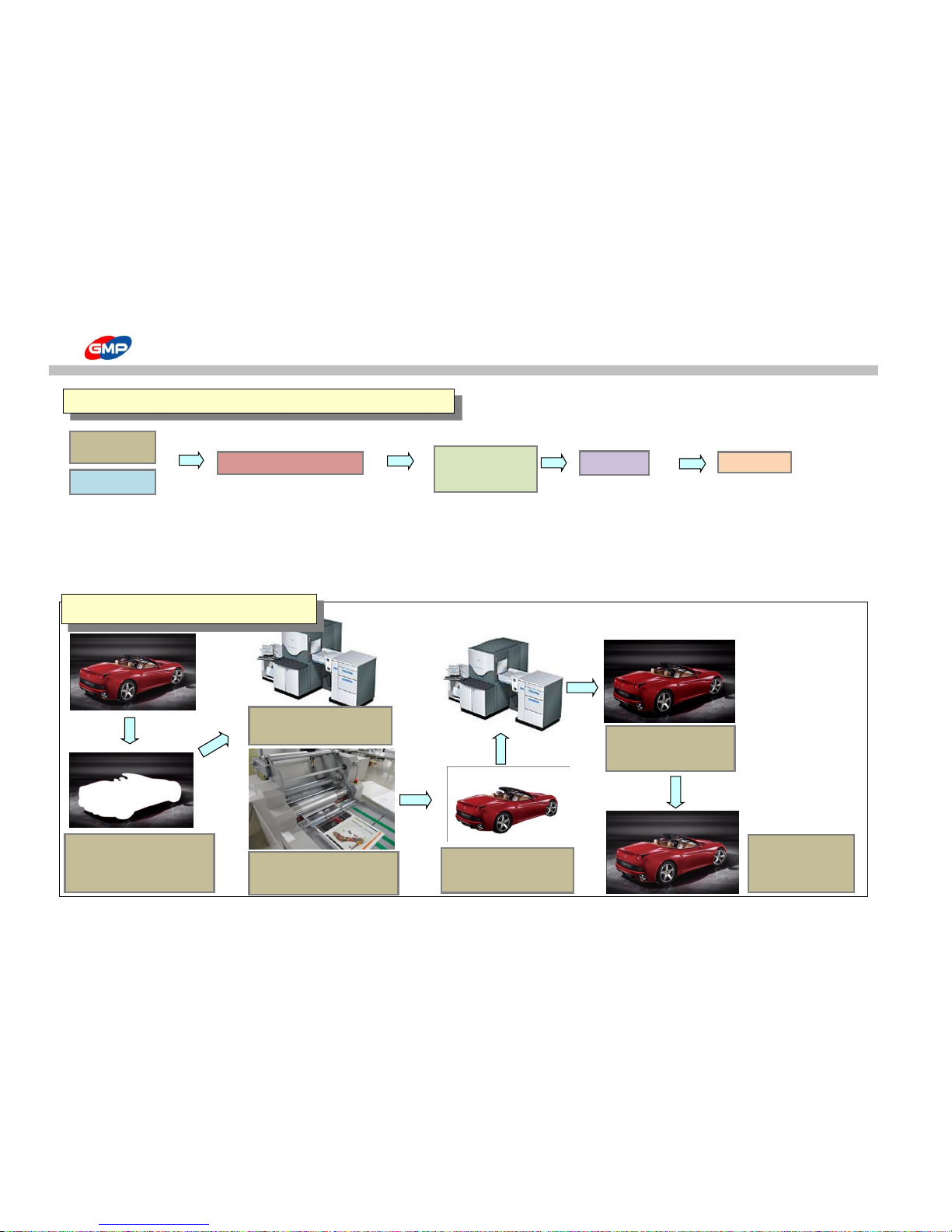
SLEEKING (GLOSS & MATT FINISH)
Refer to the Table 1.1
② Spot Gloss / Matt Sleeking
PRINTER LAMINATOR
HP INDIGO 3500
PROTOPIC III - 540
XEROX 5252
EUROLAM III - IDH 540
PIONEER - IDH5500PLUS
POD Prints
(DIGITAL PRINT)
LAMINATING
POD Prints
(DIGITAL PRINT)
SLEEKING
FINISH
OFFSET Prints
3. Spot Gloss / Matt SLEEKING SOLUTION with Lamination
1.Cut the Car Image(Picture
1.2) with Image Editing
Program
2. Print out the Background
Image only.
3. Laminate in GMP
Laminator with GMP
Sleeking Foil.
4. Print the Spot Image
on the Laminated Surface.
5. Sleeking on the
Printed Surface in
process of (Table 1.2)
6. Only the Spot
Image has Sleeking
Effect.
(Table1.3) Spot Gloss / Matt Sleeking
59/66
Page 60
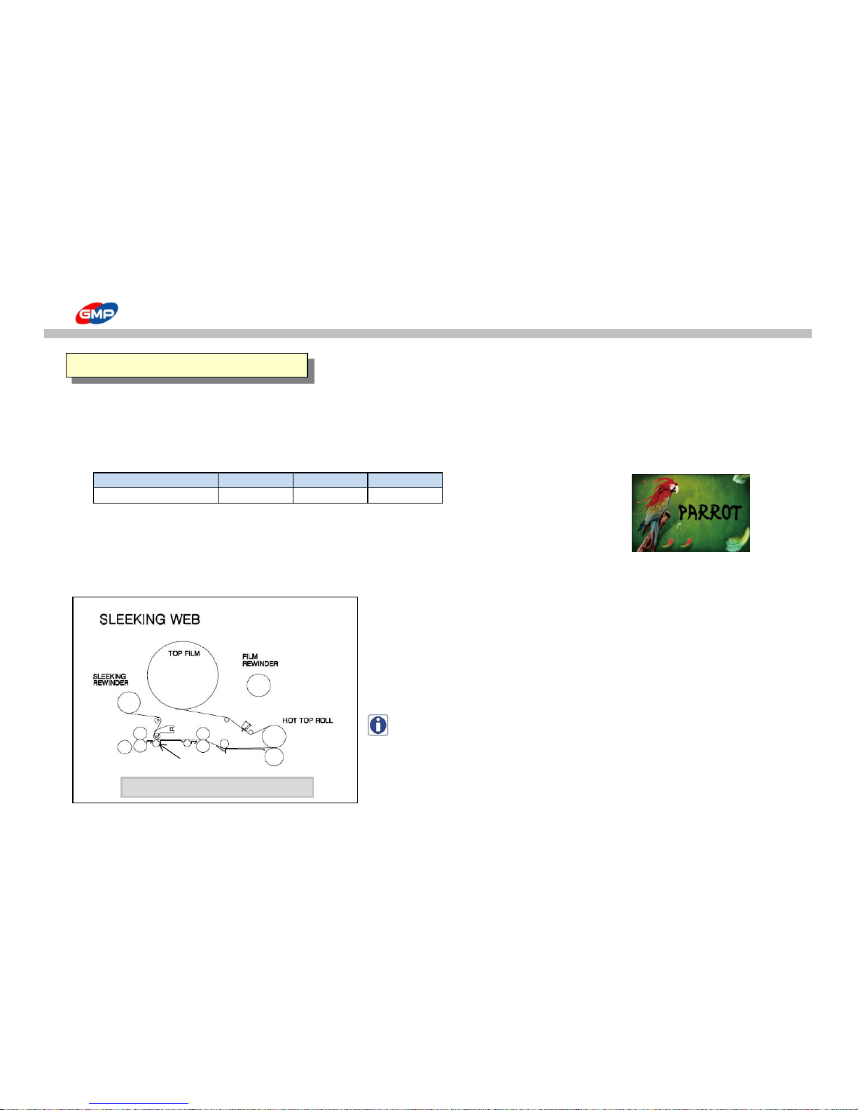
SLEEKING(HOLOGRAM FINISH)
GMP Hologram Sleeking Foil makes added-value products for Toner based Digital Prints.
Conditions for HOLOGRAM SLEEKING FOIL HOLOGRAM SLEEKING FOILS
Model
Speed Set Temp.(℃) Pressure (MPa)
① SPARKLE-HOLOGRAM
PROTOPIC III Series
3 105 0.5
② HIPER PLAID-HOLOGRAM
③ CRYSTAL-HOLOGRAM
(Table 2.1) ④ MILKY WAY-HOLOGRAM
⑤ STAR-HOLOGRAM
⑥ SPECTRUM-HOLOGRAM
⑦ MOSAIC-HOLOGRAM (Picture 2.1)
How to load the Foils
(Picture 2.2)
NOTE : This is for sleeking operation to display gloss/matt, hologram,
gold/silver foil in various effect.
The method of installation of Sleeking Idle Bar is as How to use
the Main Devices.
1.HOLOGRAM SLEEKING
PROTOPIC AUTO- 540 HS
SLEEKING IDLE BAR
60/66
Page 61
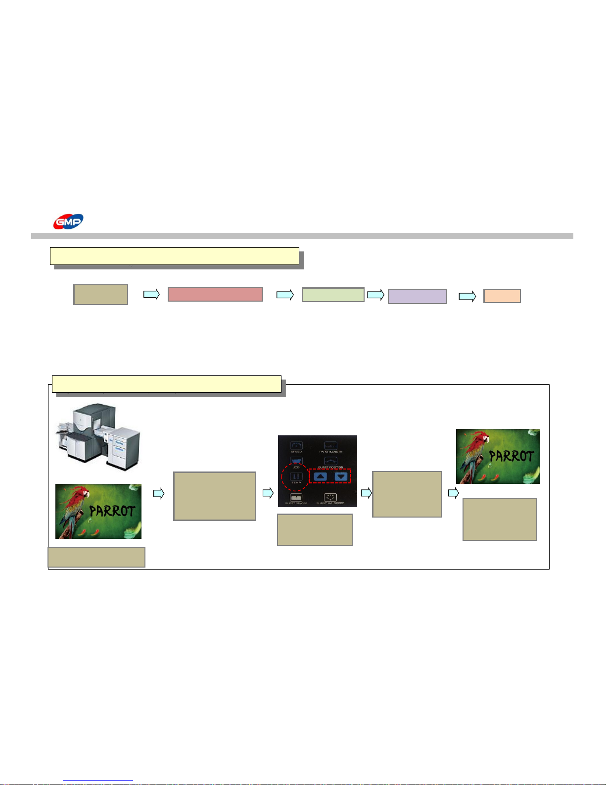
SLEEKING(HOLOGRAM FINISH)
① Whole Page Hologram Sleeking
PRINTER FILM
HP INDIGO 3500 HOLOGRAM SLEEKING FOIL
Refer to the Picture 2.1 Temp. / Speed Setting
XEROX 5252 LAMINATOR
Refer to the Table 2.1
PROTOPIC III - 540
EUROLAM III - IDH 540
PIONEER - IDH5500PLUS
POD Prints
(DIGITAL PRINT)
FILM & LAMINATOR
Foil Loading
SLEEKING
FINISH
2. Whole Page HOLOGRAM SLEEKING SOLUTION
1. Print out the POD prints.
3.Setting with
- Roller Temp:105℃
- Speed:3
4. Put substrates
on the Feeding
Table and press
"RUN".
5.Hologram
Sleeking Effect on
the Whole Page.
(Table.2.2) Whole Page Hologram Sleeking - with Prints
2. Sleeking on the
Printed Surface in
process of (Table 1.2)
61/66
Page 62
SLEEKING(HOLOGRAM FINISH)
② Spot Hologram Sleeking
Temp. / Speed Setting
PRINTER
Refer to the Table 2.1
HP INDIGO 3500
XEROX 5252
POD Prints
(DIGITAL PRINT)
POD Prints
SLEEKING
FINISH
OFFSET Prints
(Table.2.3) Spot Hologram Sleeking
2. Spot HOLOGRAM SLEEKING SOLUTION
1.Cut the Carrot Image(Picture
2.1) with Image Editing Program
3. Print the Background
Image.
6. Only the Spot Image has
Hologram Sleeking Effect.
2. Sleeking on the Printed
Surface in process of (Table 2.2)
62/66
Page 63
SLEEKING(HOLOGRAM FINISH)
③ Spot Hologram Sleeking
PRINTER LAMINATOR
Refer to the Table 2.1
HP INDIGO 3500
PROTOPIC III - 540
XEROX 5252
EUROLAM III - IDH 540
PIONEER - IDH5500PLUS
POD Prints
(DIGITAL PRINT)
LAMINATING
POD Prints
(DIGITAL PRINT)
SLEEKING
FINISH
OFFSET Prints
3.Spot HOLOGRAM SLEEKING SOLUTION - with Lamination
(Table.2.4) Spot Hologram Sleeking - with Lamination
1.Cut the Carrot
Image(Picture 2.1) with
Image Editing Program
2. Print out the
Background Image only.
3. Laminate in GMP
Laminator with GMP
Sleeking Foil.
4. Print the Spot
Image on the
Laminated Surface.
5. Sleeking on the Printed Surface
in process of (Table 2.2) d
6. Only the Spot Image
has Sleeking Effect.
63/66
Page 64
METALLIC SLEEKING
GMP METALLIC SLEEKING FOIL makes different effect on the printed area for highlight.
Conditions for METALLIC SLEEKING FOIL METALLIC SLEEKING FOIL
① GOLD
Model
Speed Set Temp.(℃) Pressure (MPa)
② SILVER
PROTOPIC III Series
3 110 0.5
(Table 3.1)
How to load the Foils (Picture 3.1)
(Picture 3.2)
NOTE : This is for sleeking operation to display gloss/matt, hologram,
gold/silver foil in various effect.
The method of installation of Sleeking Idle Bar is as How to use
the Main Devices.
1.SPOT METALLIC SLEEKING
PROTOPIC AUTO- 540 HS
SLEEKING IDLE BAR
64/66
Page 65
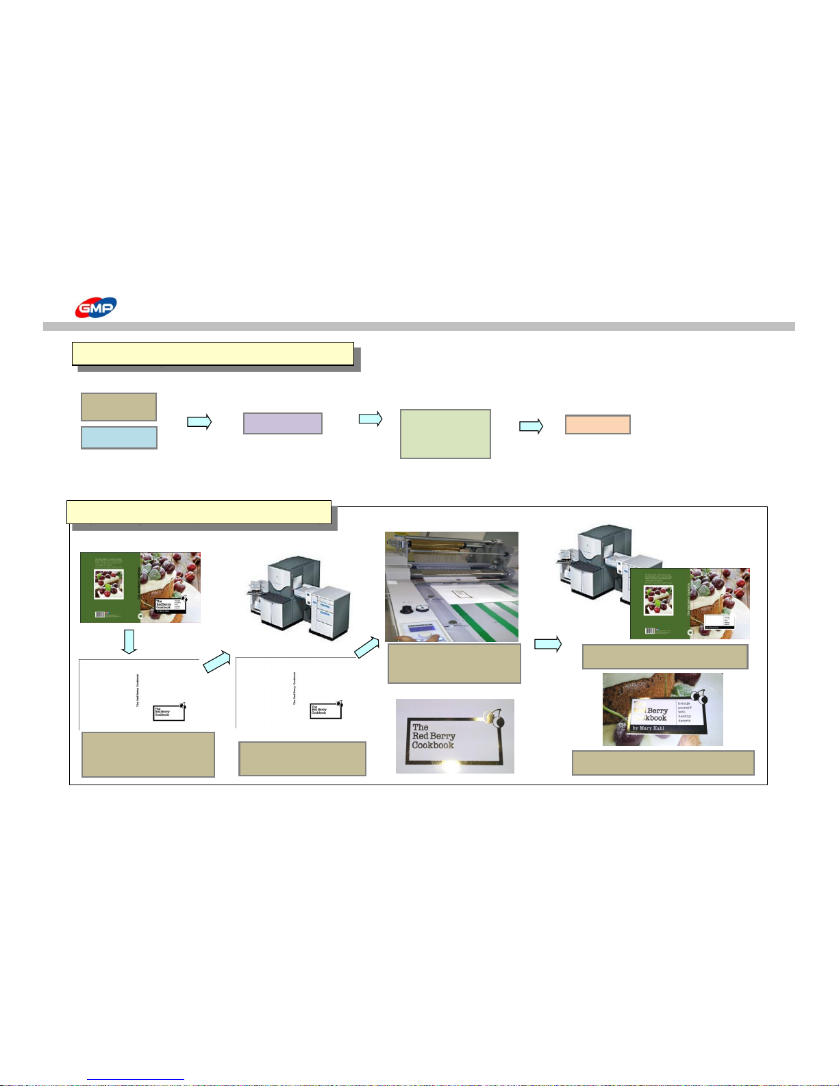
METALLIC SLEEKING
① Spot Gold/Silver Metallic Sleeking
PRINTER
Temp. / Speed Setting
HP INDIGO 3500
Refer to the Table 3.1
XEROX 5252
2. Spot METALLIC SLEEKING
POD Prints
(DIGITAL PRINT)
POD Prints
(DIGITAL PRINT)
SLEEKING
FINISH
OFFSET Prints
(Table.3.3) Spot Gold/Silver Metallic Sleeking
5.Only Spot Image has the Sleeking Effect.
1.Cut the Spot
Image(Picture 3.1) with
Image Editing Program
2. Print out the Spot Image
only.
3. Laminate in GMP
Laminator with GMP Sleeking
Foil.
4. Print the Background Image.
65/66
Page 66
FILM SPECIFICATION
MEATALLIC FOIL (GOLD,SILVER,BLUE,GREEN,RED,VIOLET,PINK)
SINGLE COLOR FOIL
3000M
MULTI COLOR FOIL
3000M
HOLOGRAM FOIL
3000M
SLEEKING FOIL
GLOSS
77CORE * 1000M,2000M
MATT 77CORE * 1000M,2000M
DUAL 77CORE * 1000M,2000M
HOLOGRAM SLEEKING FOIL - SPECTRUM,MILKYWAY,CRYSTAL,STAR,MOSAIC,SPARKLE,HYPER PLAID
HOLOGRAM SLEEKING FOIL-PET12
77CORE * 1000M
HOLOGRAM SLEEKING FOIL-PET25
77CORE * 1000M
HOLOGRAM SLEEKING FOIL-PET50
77CORE * 1000M
HOLOGRAM FOIL-UV20
77CORE * 1000M
HOLOGRAM FOIL-UV30
77CORE * 1000M
SLEEKING FILM
66/66
 Loading...