

Page 1
Page 1
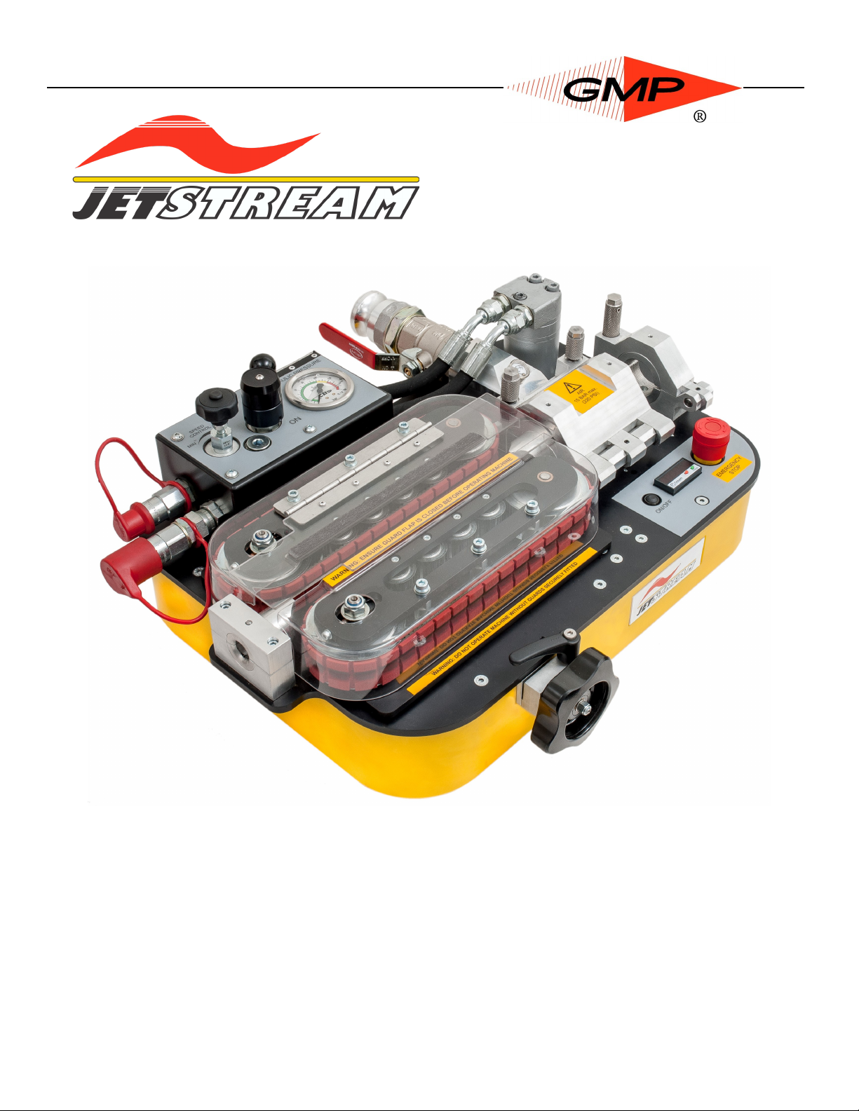
General Machine Products (KT), LLC
Operation and Maintenance
Model 89950
All rights reserved. No part of this publication may be copied, reproduced or transmitted in any form whatsoever without the written permission of General Machine Products (KT), LLC
General Machine Products (KT), LLC • 3111 Old Lincoln Hwy • Trevose, PA 19053 • USA
TEL: +1-215-357-5500 • FAX: +1-215-357-6216 • WEB: www.gmptools.com
CABLE BLOWING MACHINE
Manual P/N 33829 Ver 5b
050319 AKK
Page 2
Page 2
General Machine Products (KT), LLC
Rev.no Date Details Author
01 Feb 28 2014 Original issue C. Swallow
02 April 21 2014 Reformat for US A. Konschak
03 August 25 2015 Added Relief Valve Settings A. Konschak
04 September 16 2015
Cleaned up content
Added metric cable options
A. Konschak
04a October 05 2016
Updated photo to show current air connection
Updated toolkit
A. Konschak
04b January 23 2017 Toolkit number correction A. Konschak
04c April 20 2017 Updated specifications on P8 A. Konschak
05 April 25 2017
Relief valve settings updated
Location of pressure switch
adjustment updated
Procedure to set the pressure
relief valve added
A. Konschak
05a July 17 2017 Change company name A. Konschak
05b May 03 2019
Page 33—Configured cable collets and guide
inserts as a single number kit
A. Konschak
REVISION HISTORY:
Page 3

Page 3
General Machine Products (KT), LLC
CONTENTS
1.0 Safety Instructions
2.0 Critical Points
3.0 General Description
4.0 Specification
5.0 Operating procedures
6.0 Maintenance
7.0 Procedure for changing inserts in the duct clamp
8.0 Procedure for changing inserts in the air box
9.0 Procedure for changing inserts in the infeed guides
10.0 Procedure for replacing the air box housing seal
11.0 Procedure for changing the cable drive belts
12.0 Procedure for tensioning the drive belts
13.0 Procedure for checking and replacing the motor drive belt
14.0 Procedure to set the Pressure Switch
15.0 Procedure to set the Pressure Relief Valve
16.0 Monthly Service – check list
17.0 Service History Record
18.0 Duct integrity and Lubrication
19.0 Troubleshooting
20.0 Battery Replacement
21.0 Toolkit
22.0 Spares
APPENDICES
Appendix 1 Cable and duct insert selection chart.
Appendix 2 Counter/Rate meter Programming Instructions
Page 4

Page 4
General Machine Products (KT), LLC
1.0 SAFETY INSTRUCTIONS
THIS EQUIPMENT SHOULD BE USED ONLY BY PERSONNEL WHO HAVE BEEN GIVEN THE AP-
PROPRIATE TRAINING, AND WHO ARE COMPETENT TO USE IT.
THESE INSTRUCTIONS ARE TO BE MADE AVAILABLE TO OPERATORS OF THIS EQUIPMENT AT
ALL TIMES, FAILURE TO OBSERVE THESE SAFETY INSTRUCTIONS COULD RESULT IN SERIOUS
PERSONAL INJURY AND/OR PROPERTY DAMAGE.
WORK AREA AND GENERAL SAFETY
1. Read and understand the operation and maintenance manual supplied with this equipment. Keep it in
a convenient place for future reference.
2. Keep children and untrained personnel away from this equipment while in operation.
3. Keep all guards and safety devices in place. Do not operate this equipment with guards removed or
damaged.
4. Keep hands, feet and loose clothing away from moving parts, especially at cable entry points.
5. Always stop the machine and isolate compressed air, electrical and hydraulic services to carry out lu-
brication and servicing.
6. Check machine before starting for worn or damaged parts. Check for signs of loose nuts and bolts
etc.
7. If machine is left unattended, ensure that unauthorized use is prevented.
8. Never leave the machine unattended while in use.
9. Consider the use of safety barriers, especially when used in public places; observe all statutory re-
quirements for working environments.
10. Beware of pinch points involved with rotating components,
11. Beware of hot surfaces, machine uses compressed air and hydraulic services.
12. When operating machine always wear appropriate safety clothing, ear defenders, eye protection, hard
hat, safety shoes and leather gloves, machine operates with compressed air at up to 220 psi (15 Bar)
and hydraulic oil at up to 1015 psi (70 Bar).
13. The main machine assembly is in excess of 25 kg (55 lb). When lifting care must be taken, ensure
sufficient man power/lifting gear is available, to prevent personal injury and damage to the machine.
14. Prior to installation ensure the duct route is connected properly.
15. Beware of exposed electrical contacts. Do not touch, or allow metal objects to come into contact.
16. Waste hydraulic oils are to be disposed of via an environmentally acceptable method – e.g. passed on
for re-cycling.
17. Machine may cause additional fire hazard if involved in an existing fire due to compressed air and hy-
draulic oils.
18. No personnel are to be in manholes or ducts when the Cable Blowing Machine is being operated.
19. The machine must be operated on firm ground.
20. Stay clear of cables or lines under tension.
21. Stay clear of pressurised hydraulic lines, air lines and duct.
22. Only use the machine for its intended purpose, do not use the roller drive without the air chamber to
push or to retrieve cable, blow air in the far end to help cable recovery.
23. Do not place cable drum too close to the Cable Blowing Machine.
24. Do not tamper with pressure relief valves or pressure reducing valves.
25. The compressed air supply must not be allowed to enter the air chamber or duct before the belts have
been closed on to the cable. Do not turn the air on until a reasonable length of cable 300' (50m) has
been installed into the duct.
FAILURE TO DO SO MAY RESULT IN PERSONAL INJURY, AS THE CABLE COULD BE EJECTED FROM THE CABLE BLOWING MACHINE WITH HIGH FORCE AND VELOCITY.
26. Ensure the cable drum rotates freely on its stand; the cable should leave from the top of the drum.
27. The cable should enter the machine in a clean and dry condition. In damp, dusty atmospheres, the
cable should be cleaned continuously as it enters the machine.
28. Do not open the air chamber until all the air has been exhausted and the air pressure gauge reads ze-
ro.
29. To prevent damage to the hydraulic hoses and the emergency stop cable never leave them on the
ground when not in use.
Page 5

Page 5
General Machine Products (KT), LLC
GENERAL HYDRAULIC SAFETY INSTRUCTIONS
The GMP Jetstream Cable Blowing Machine has a high pressure hydraulic drive and control system.
Please observe the following precautions when operating the Jetstream Cable Blowing Machine:-
Always connect the power pack hoses to the Jetstream prior to starting the power pack engine. Failure to
do this may cause severe overheating of the power pack.
Ensure the ‘on/off’ control valve on the Jetstream is in the ‘off’ position prior to starting the hydraulic power
pack to prevent unwanted operation of the machine.
Always ensure the armoured cable to the hydraulic power pack is connected, this provides an essential
emergency cut off facility.
Escaping fluids under pressure can penetrate the skin and cause serious personal injury. Observe the following precautions to avoid hydraulic hazards: -
Ensure all hydraulic connections are securely tightened before operating the machine.
Check for leaks with a piece of cardboard. Do not use your hands!
Do not exceed working pressure of hydraulic hoses.
Visually inspect hoses regularly and replace if damaged.
GENERAL PNEUMATIC SAFETY INSTRUCTIONS
The GMP Jetstream Cable Blowing Machine is a pneumatic device, using pressurised air to project cable
at high velocities. Please observe the following precautions when operating the Cable Blowing Machine:-
Compressed air can cause flying debris. This could cause personal injury. Always wear personal protective equipment.
Ensure no personnel are in the manhole at the far end of the cable run. Severe personal injury may result.
Never open the air chamber when pressurised.
Only AUTHORIZED, fully trained personnel should operate the air compressor.
GENERAL ELECTRICAL SAFETY INSTRUCTIONS
The machine has electrical monitoring and safety circuits. Observe the following precautions to avoid elec-
trical hazards:
Do not operate in water. Do not expose the machine to rain.
Always ensure the armoured cable to the hydraulic power pack is connected, this provides an essential
emergency cut off facility.
Page 6

Page 6
General Machine Products (KT), LLC
2.0 CRITICAL POINTS THAT DRAMATICALLY AFFECT THE
OPERATION OF THE CABLE BLOWING MACHINE
• PRESSURE ON THE CABLE (POSITION OF THE ADJUSTMENT WHEEL) SHOULD BE SET AS
PER THE INSTRUCTIONS
• BELTS TO BE CLOSED AT ALL TIMES WHEN CABLE IS INSTALLED INTO MACHINE.
• CORD SEALS IN AIR CHAMBER IN GOOD CONDITION AND CORRECTLY FITTED TO PROVIDE
GOOD SEALING.
• CORRECT CABLE SEAL FITTED.
• DUCT/INNER-DUCT FULLY CONNECTED AND PRESSURE TESTED.
• DUCT AND CONNECTING FITTINGS ARE SUITABLE FOR OPERATING AT 220 psi (15 BAR) AIR
PRESSURE.
• DUCT CLAMP SECURELY TIGHTENED.
• COMPRESSOR CAPACITY SUITABLE FOR DIAMETER OF INNER-DUCT BEING USED (SEE
SECTION 4) @ UP TO 220 psi (15 BAR) (HIGHER PRESSURE GIVES BETTER PERFORMANCE).
• CABLE DRUM MUST BE LOCATED DIRECTLY BEHIND AND IN LINE WITH THE BLOWING
MACHINE.
• AIR CHAMBER, DRIVE BELTS AND PULLEYS, CABLE GUIDES, MUST BE CLEAN AND FREE
FROM DEBRIS, SLUDGE, DIRT, WATER AND LUBRICANT.
• THE CABLE MUST BE HAND GUIDED INTO THE BLOWING MACHINE THROUGH A DRY CLEAN
CLOTH BY THE OPERATOR WEARING WORK GLOVES.
• ENSURE THE COMPRESSED AIR SUPPLY IS NOT APPLIED TO THE CABLE UNTIL
APPROXIMATELY 300' (100 METERS) OF CABLE HAVE BEEN INSTALLED OR THE
HYDRAULIC PRESSURE BEGINS TO RISE.
• THE HYDRAULIC PRESSURE SHOULD BE BETWEEN 290-435 PSI (20-30 BAR) AT THE
START OF A BLOWING INSTALLATION. IF GREATER DO NOT PROCEED. CHECK
CABLE ADJUSTMENT WHEEL SETTING, INNER-DUCT, CABLE, CABLE SEALS, CABLE
COLLET SIZES. RECTIFY BEFORE RE-COMMENCING THE INSTALLATION.
• ALWAYS FIT THE HYDRAULIC HOSE DUST CAPS WHEN THE HOSE IS NOT IN USE,
CLEAN AND CHECK THE QUICK RELEASE COUPLINGS BEFORE USE.
DISCLAIMER
General Machine Products takes care in the design of its products to help ensure that the cable is
protected during installation. Due to the variety and different methods of cable manufacture the
responsibility of checking the cable compatibility with the equipment lies with the operator.
Therefore, GMP cannot accept liability for any damage to the cable.
Page 7
Page 7
General Machine Products (KT), LLC
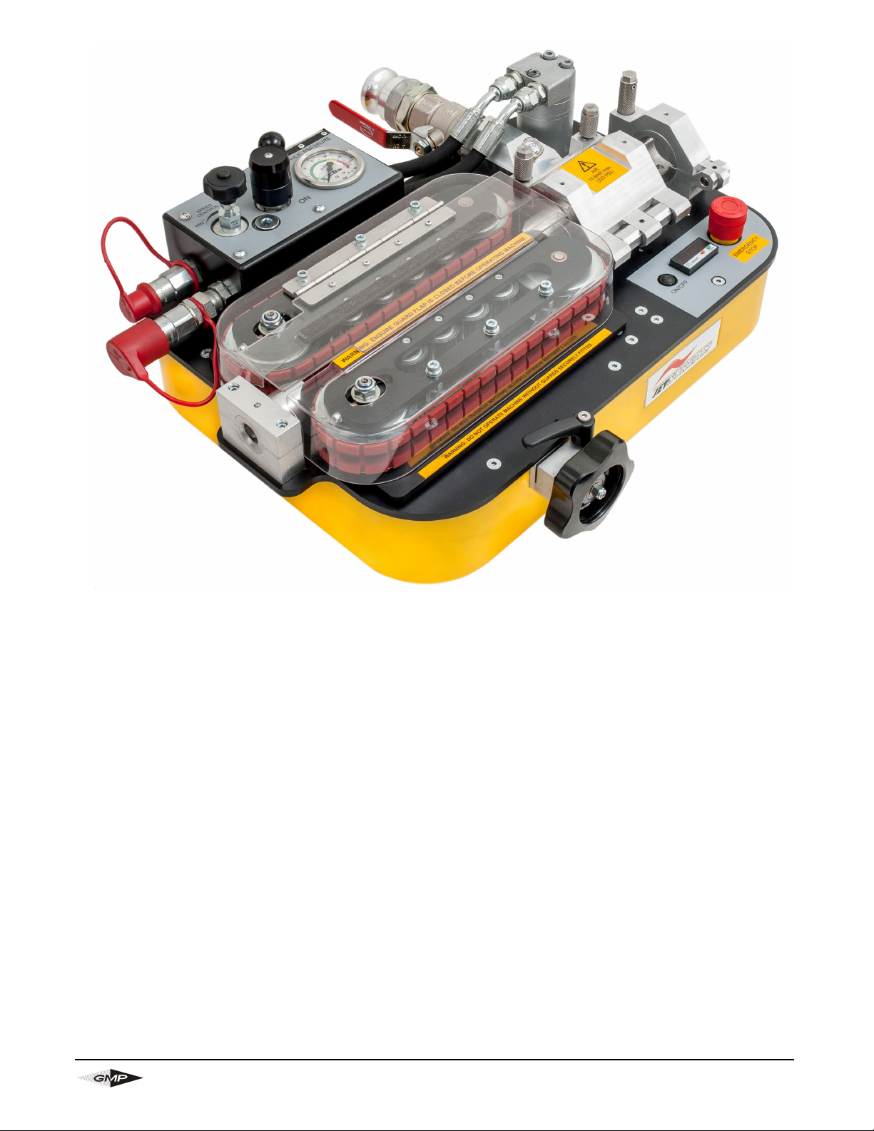
3.0 GENERAL DESCRIPTION
The GMP Jetstream machine is designed to provide an effective and safe method of fiber optic cable
installation. The system installs fiber optic cable of 4-20mm outside diameter at up to 280 ft/min (85m/min)
into pre-installed inner-ducts, employing the viscous drag compressed air principle.
The machine feeds compressed air into the inner-duct via the air box and uses a hydraulic motor and
reduction gearing to drive a pair of compliant belts (both belts are driven). This system is protected by a
pre-set pressure relief valve and pre-set pressure sensor. The electronic monitoring system provides read
out of speed and distance and automatic protection against duct obstruction.
The belts are covered with a compliant coating to help prevent damage to the cable. The belts offer a large
surface area in contact with the cable ensuring high grip with reduced compressive loading.
During installation, the torque applied to the cable by the belts adjusts automatically up to a pre-set
maximum value (after which the machine will shut down) to help prevent damage to the cable. A full range
of accessories is available to allow the machine to handle a wide range of cables and ducts.
The machine may be placed on the ground or on a support to bring the cable to a suitable height. A
separate reinforced transit case is provided; this will help protect the machine from damage during transit
and can be used as a support for the machine when being used to install cable.
The unit is CE approved.
Page 8
Page 8
General Machine Products (KT), LLC
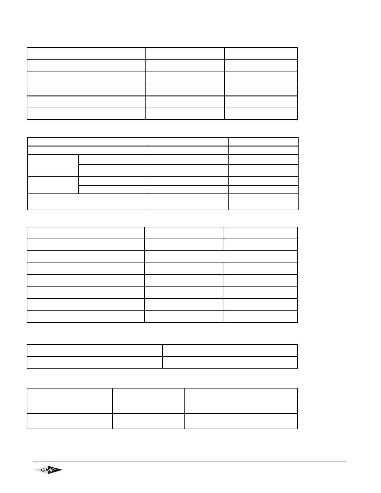
Weight 68 lbs. approx. 31kg approx.
Weight including case 132 lbs. approx. 60kg approx.
Dimensions (height x
length x width)
9 1/4"x 24 1/2" x 19"
233mm x 620mm x 484mm
DIMENSION AND WEIGHTS
Minimum air hose bore:
1 ¼"
32mm
Maximum air pressure: 210 psi 15 Bar
For Ducts with an Inner Diameter of: Minimum Flow Acceptable
up to 25mm 150CFM 4m³/min
26 up to 30mm 185CFM 5m³/min
31 up to 35mm 250CFM 7m³/min
36 up to 40mm 375CFM 10m³/min
41 up to 44mm 450CFM 12m³/min
PNEUMATIC SYSTEM
Maximum operating pressure: 1015 psi 70 Bar
Recommended flow: 4 gal/min (US) 15 l/min
Pressure
switch setting:
12-20mm OD Cable 1015 psi 70 Bar
4 -12mm OD Cable 725 psi 50 Bar
12-20mm OD Cable 1160 psi 80 Bar
Relief Valve
setting
4-12mm OD Cable 870 psi 60 Bar
Initial starting pressure:
(if greater the set-up needs checking)
290-435 psi 20-30 Bar
HYDRAULIC DRIVE SYSTEM
4.0 SPECIFICATION
Power requirement: 18 Vdc (2 x 9v cells)
Fuse rating: 315 mA
ELECTRONIC MONITORING SYSTEM
Cable size:
0.158" to 0.787"
ø4 to ø20mm
Duct size: (OD Controlled)
3/4 - 1 1/2" SDR
Duct size: (OD Metric)
ø10 to ø50mm
Cable speed: 0-280 ft/min 0-85m/min.
Maximum pushing force: 132 lbs. 60kg
Ambient Temperature Range
32-104 °F 0-40 °C
OPERATING CAPACITIES
Page 9
Page 9
General Machine Products (KT), LLC
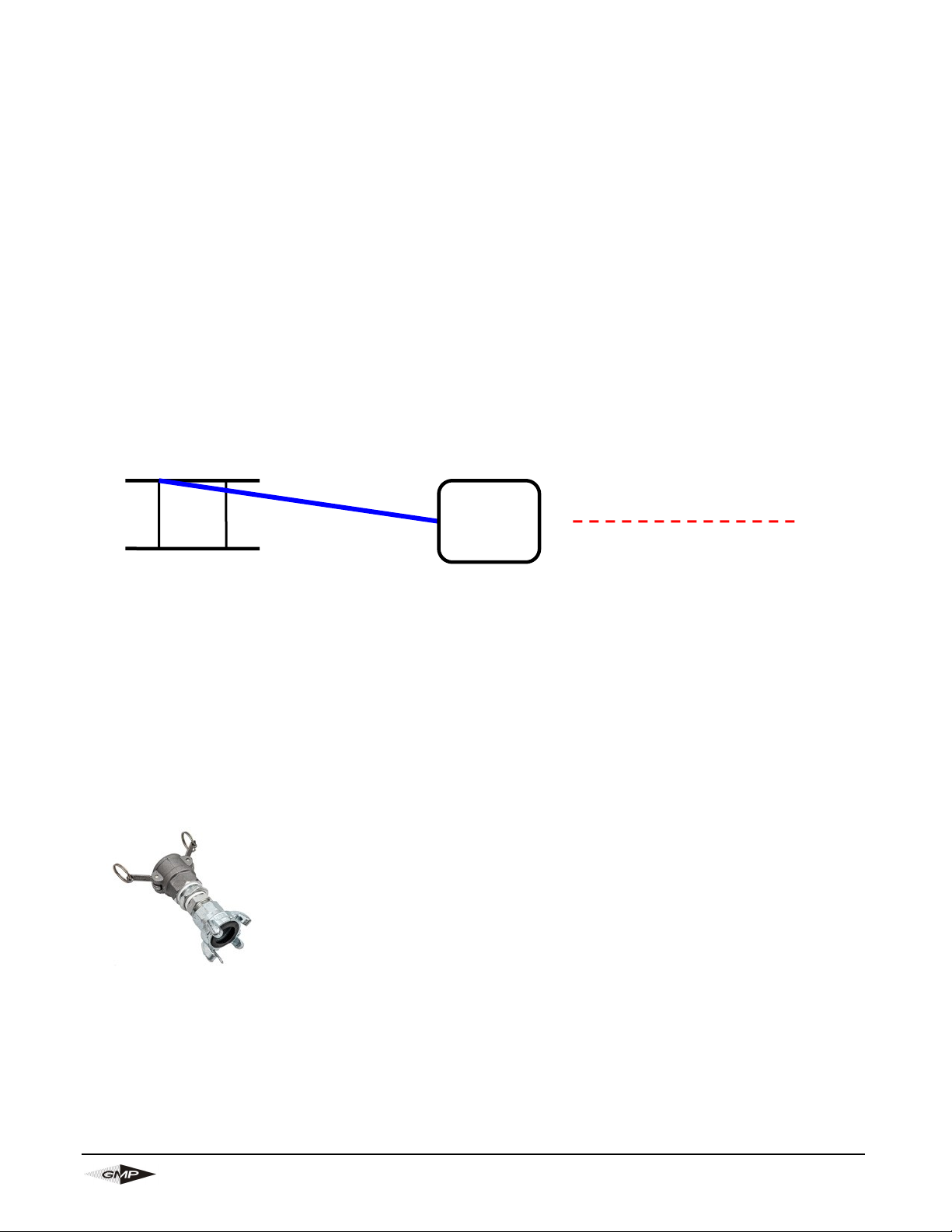
Jetstream machine
Duct route
Cable drum
5.0 OPERATING PROCEDURE
IT IS IMPERATIVE THAT ALL PERSONS USING, OPERATING OR MAINTAINING THIS
CABLE BLOWING MACHINE:
• HAVE RECEIVED COMPREHENSIVE TRAINING IN THE USE OF THIS MACHINE.
• ARE COMPETENT TO USE IT,
• AUTHORIZED TO USE IT AND
• HAVE READ AND UNDERSTOOD THIS MANUAL
GENERAL MACHINE PRODUCTS CANNOT BE HELD RESPONSIBLE FOR MISUSE OF THIS
EQUIPMENT.
Set up for installing cable with the machine mounted above ground:
Position the machine in line with the route of the duct.
Position the cable drum behind the machine and in line with the machine. See sketch below (this shows a
plan view of the recommended set up).
Ensure the machine is secure (either on its own stand or a separate suitable stand).
Ensure the machine is fitted with the appropriate guides and collets to suit the cable being installed and
ducts into which the cable is to be installed. (See Appendix 1 for details of interchangeable parts and
sections 7, 8 & 9 for procedures on how to fit these parts).
To set the machine up to install cable it will be necessary to:
1. Select and set the appropriate pressure switch setting for the cable being installed.
2. Fit the duct into which the cable is to be installed into the air box and duct clamp.
3. Fit the cable through the machine.
4. Connect the air supply to the machine1.
5. Connect the hydraulic power input to the machine.
1
use the supplied 4
claw to round adapter
if needed
Page 10
Page 10
General Machine Products (KT), LLC
Pressure Switch Setting
Caution
Refer to the section 4 ‘SPECIFICATION’ for the correct pressure settings for the pressure switch and to
section 14 ‘PROCEDURE TO SET THE PRESSURE SWITCH’ for the setting procedures.
NOTE: - The cable blowing machine is supplied as standard with the pressure switch set at 1015
psi (70 Bar), these settings are suitable for cables in the range 12-20mm O.D.
For cables 4 - 12mm O.D. these settings need to be changed, refer to the section 4
‘SPECIFICATION’ for the correct pressure settings for the pressure switch and to section 14
‘PROCEDURE TO SET THE PRESSURE SWITCH’ for the pressure setting procedures.
Fit the duct into which the cable is to be installed into the air box and duct
clamp.
It is recommended that a length of duct similar in size to the duct into which the cable is to be installed be
fitted in the duct clamp. This length of duct may then be connected to the installed duct (the length of duct
underground into which the cable is to be installed) using a suitable connector.
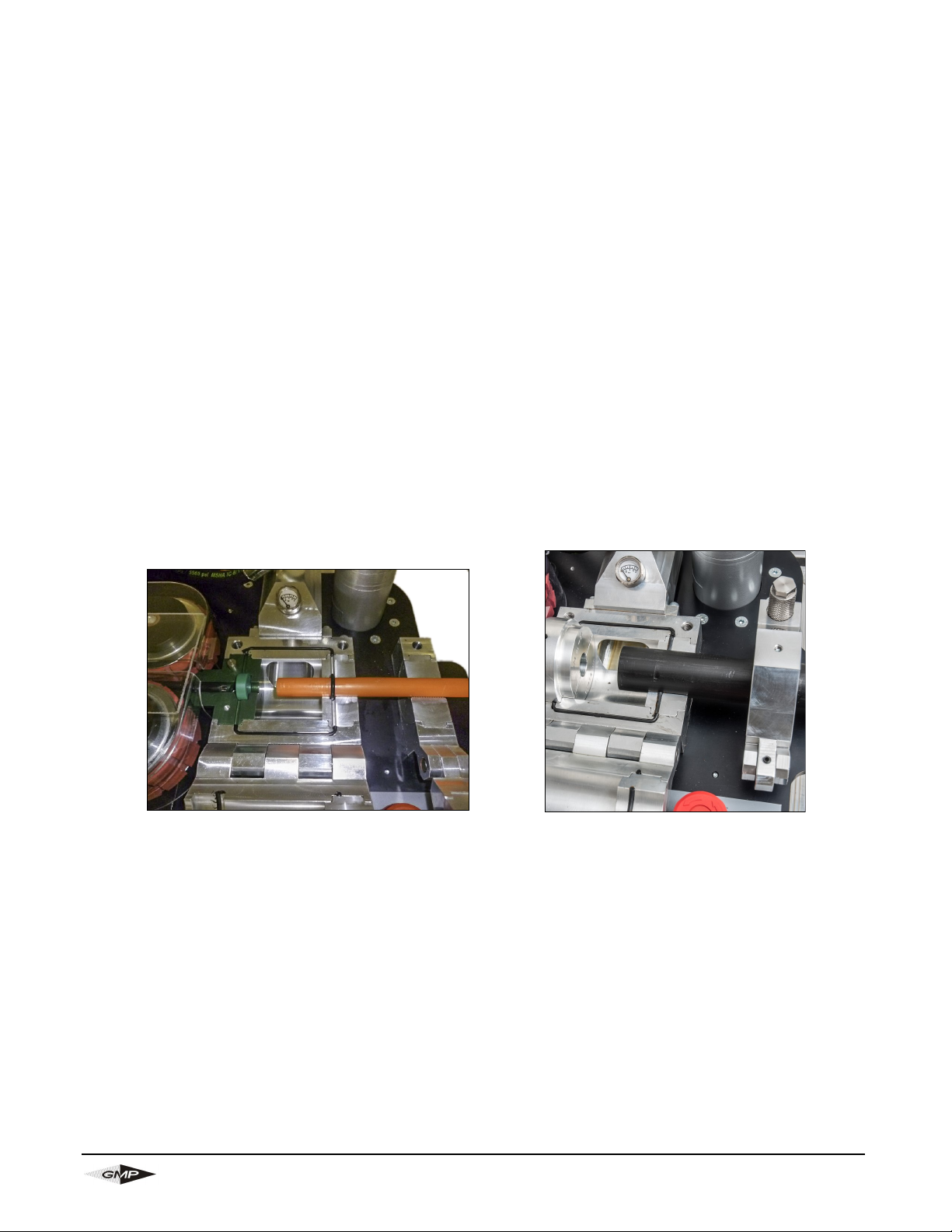
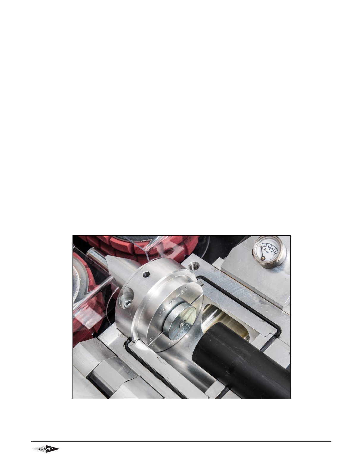
For duct sizes Ø12-22mm slide a suitable size O ring over the end of the duct.
Fit the duct into the end of the air box housing so that it protrudes half way into the housing.
For duct sizes Ø12-22mm position the O ring so that it sits against the seal face, as shown in below photo.
For duct sizes over Ø22mm, the seal is permanently located within the seal collet.
Once the duct has been positioned, the duct clamp may be closed and the locking screw tightened; the
duct is now secure.
ENSURE THAT THE INNER-DUCT IS FULLY PREPARED FOR USE, I.E.
a. FULLY CONNECTED
b. PRESSURE TESTED
c. CABLE EXIT RETAINING DEVICE FITTED
d. LUBRICATED
FOR FURTHER DETAILS ON INNER-DUCT LUBRICATION REFER TO SECTION 14.
For duct sizes over Ø22mm For duct sizes Ø12 - 22mm
Page 11
Page 11
General Machine Products (KT), LLC
Fit the cable through the machine.
It is possible to insert the cable in the machine in two different ways.
Method 1:
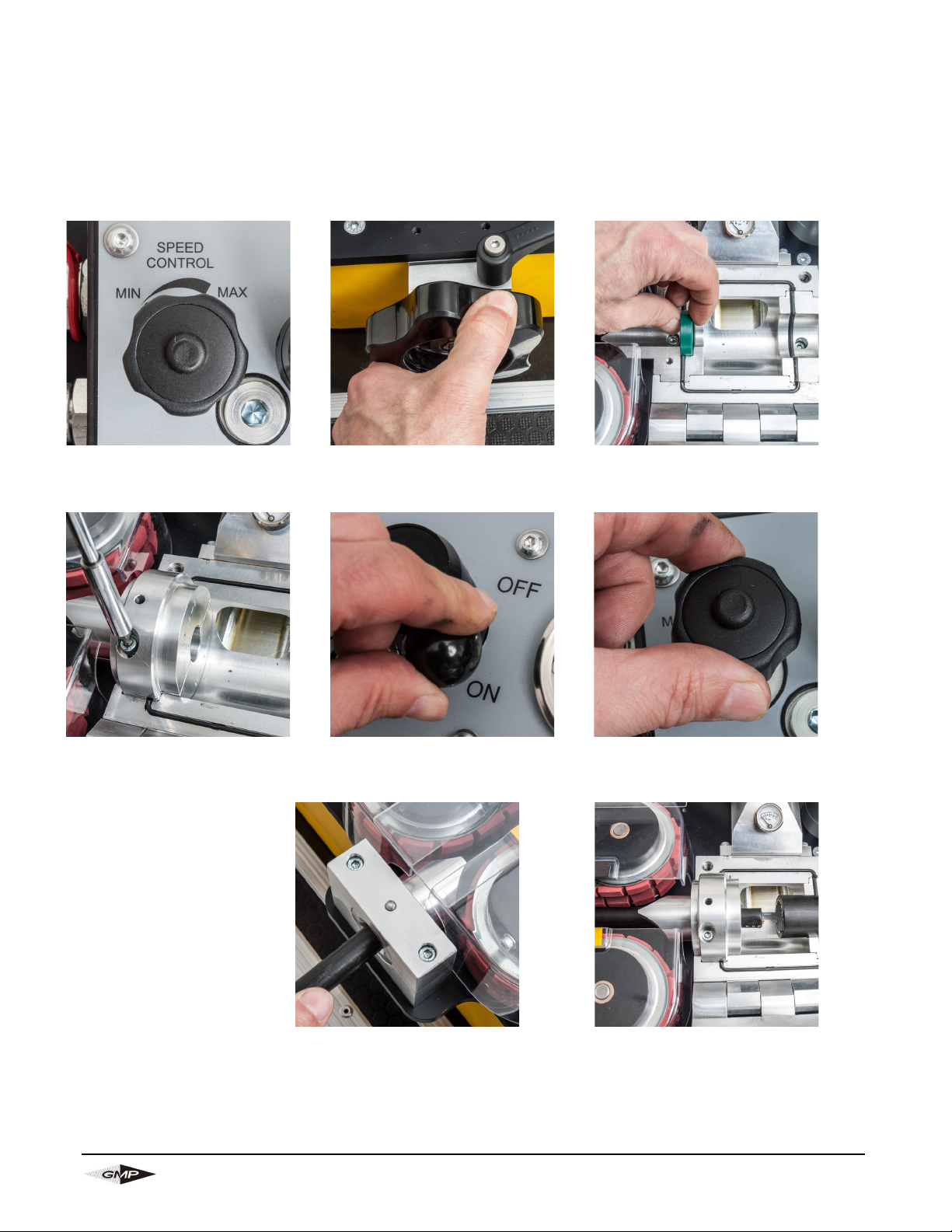
This method is only suitable if the machine has been previously set up with the correct cable guide and cable collets to suit the cable being installed, see sections 8 & 9 for the procedure for changing the guides.
Connect the two hydraulic hoses and the emergency stop cable to the power pack or hydraulic power
source. Ensure the plug to socket & socket to plug connections are correctly made.
Turn the speed control knob
all the way to minimum.
Turn the adjustment wheel fully
counter-clockwise to fully open
the drive belts
Select the appropriate split cable
seal (see appendix 1) and position
it in the groove in the cable collet.
Turn to hydraulic control valve
to the ‘ON’ position.
Slowly turn the speed control
knob clockwise until the belts
are just moving.
Replace top half of the cable
collet
Take the cable to be installed
and pass it through the cable
guide insert so that the end is
between the belts.
Close the belts (using the adjustment wheel) gently until the
cable is gripped (there is no
need to apply the full installation pressure to the cable at
this stage)
The cable should now feed slowly
through the belts, cable seal, air
box and into the duct.
Turn to hydraulic control valve to the ‘OFF’ position. Close and tighten the thumb nuts securing the airbox.
Page 12
Page 12
General Machine Products (KT), LLC
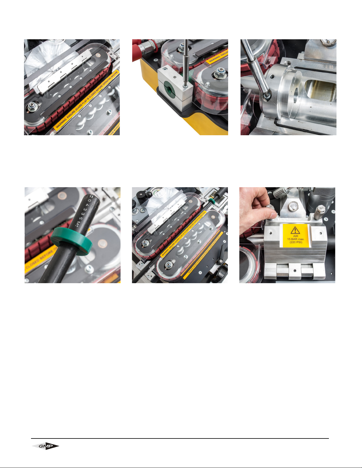
Method 2:
Open the belts fully using the adjustment wheel and lift the magnetically held guard flap.
Remove the top half of the cable
guide insert. Ensure the correct
cable guide inserts are fitted for
the cable (see appendix 1 and
section 9).
Open the airbox and remove the
top half of the cable seal collet.
Ensure the correct collets are
fitted (see appendix 1 and section 8).
Select the appropriate split cable
seal (see appendix 1) and position it around the cable.
Take the cable and simultaneously place it into the duct and
into the air box. Thread it between the belts. Ensure the cable seal seats in the appropriate
groove in the cable seal collet.
Replace the top halves of the
belt infeed guide and cable
seal collet. Close the airbox
and tighten the thumbnuts.
Page 13
Page 13
General Machine Products (KT), LLC
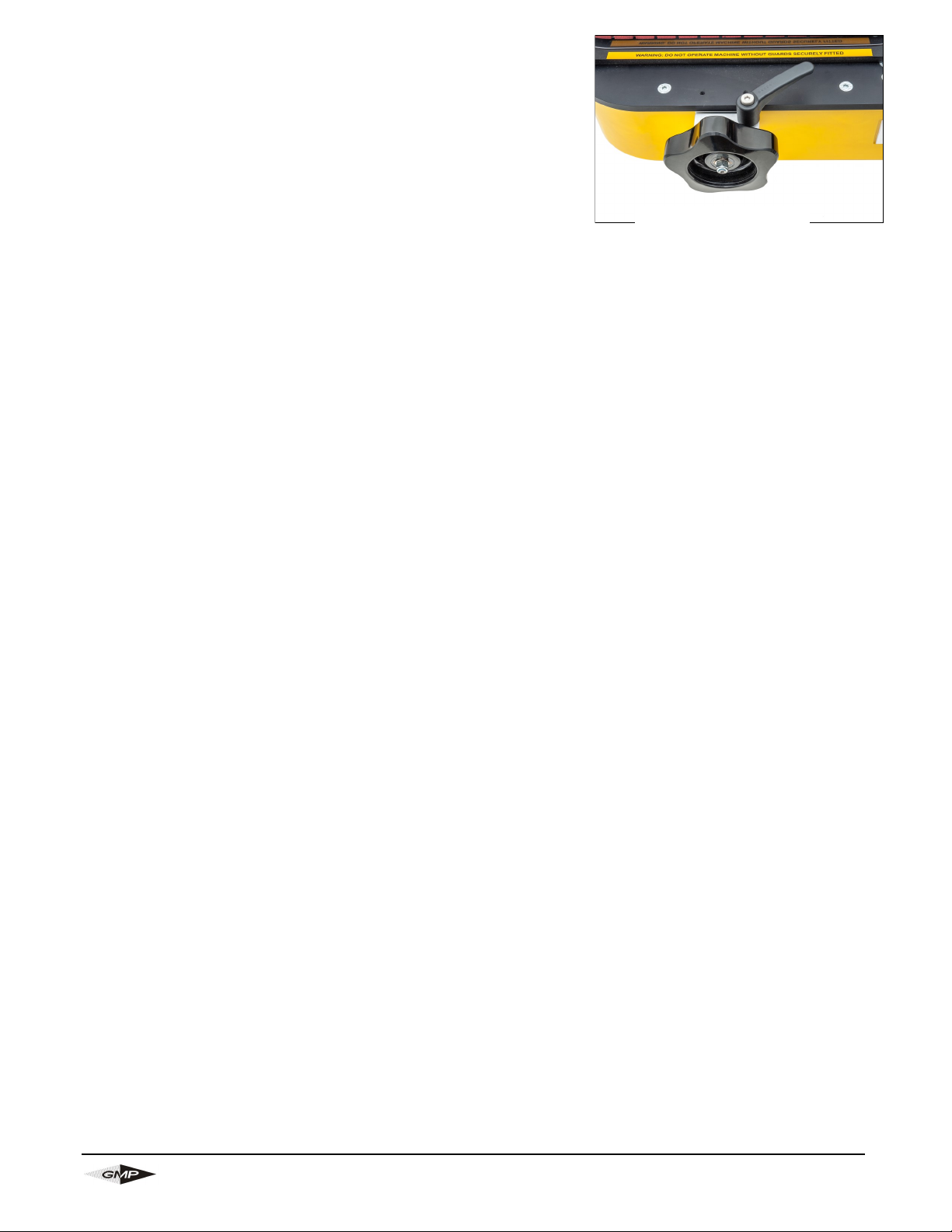
Setting the clamp force:
Close the drive roller assembly onto the cable as follows:
Loosen the locking handle by moving it in a counter-clockwise
direction. The handle can be indexed to assist in this movement.
The adjustment wheel can now be rotated to open or close the
belts. Turn the wheel clockwise to close the belts or counterclockwise to open them.
When preparing the machine to insert the cable, the belts will be
fully open (adjustment wheel wound fully counter-clockwise). Once the cable
has been positioned in the machine the belts must be closed on the cable in order to drive the cable. The
closed belts will also stop the cable being dragged back out of the machine by any tension in the cable.
Turn the adjustment wheel clockwise until the belts close onto the cable. The amount of pressure applied
to the cable can be adjusted by turning the adjustment wheel either clockwise or counter-clockwise. Once
the desired pressure has been obtained the locking handle should be tightened by turning it in a clockwise
motion. The handle can be indexed to assist in this movement.
As more experience is gained using the machine, the amount of compression required will become clear.
Adjustment Wheel
Locking Handle
Page 14

Page 14
General Machine Products (KT), LLC
Set up for installing cable with the machine mounted below ground:
The set up is similar to the set up for installing cable above ground. Typically this type of installation is
used for “series blowing” i.e. when a length of cable is already installed, and the limit of installation
distance is reached. In such cases it is customary to couple a “series machine” located down a manhole
some distance from the point of main installation. This machine operates in conjunction with the machine
located at the main point of installation. The GMP Jetstream machine is capable of this type of operation,
it may be coupled with a second machine to increase the distance a single cable can be installed without
splices. The only difference between this set up, and the set up for installing cable with the machine
above ground, is that there will be no drum stand carrying the cable drum. The cable will be exiting from
one side of the manhole and blown into the duct at the other side of the manhole. The machine should be
aligned with both the incoming cable and the outgoing duct path, both side to side and up and down.
NOTE: THE MACHINE MUST NOT BE SUBMERGED IN WATER.
If the hole is full of water it must be pumped out before placing the machine on the bottom of the hole.
Connect the hydraulic supply to the machine.
Note: - Please refer to Section 4.0 Specification for details on recommended flow and pressure
requirements.
Ensure that both the hydraulic control lever is in the ‘OFF’ position and that the speed control knob is in the
fully minimum position (fully rotated counter-clockwise). The emergency stop also needs to be set in the
upper position, twist counter-clockwise to ensure this is the case.
Connect the two hydraulic hoses and the emergency stop cable to the power pack (or hydraulic power
source). Ensure the plug to socket & socket to plug connections are correctly made.
NOTE:
NEVER RUN THE JETSTREAM WITHOUT THE EMERGENCY STOP CABLE BEING CONNECTED.
ONLY AUTHORIZED, FULLY TRAINED OPERATORS SHOULD BE ALLOWED TO OPERATE THE
HYDRAULIC POWER PACK (OR HYDRAULIC POWER SOURCE).
The machine is now ready to start the cable installation.
Page 15
Page 15
General Machine Products (KT), LLC
Installing cable.
The machine is fitted with a range of controls to help the operator to install cable in the minimum time with
the least risk of causing damage to the cable or duct.
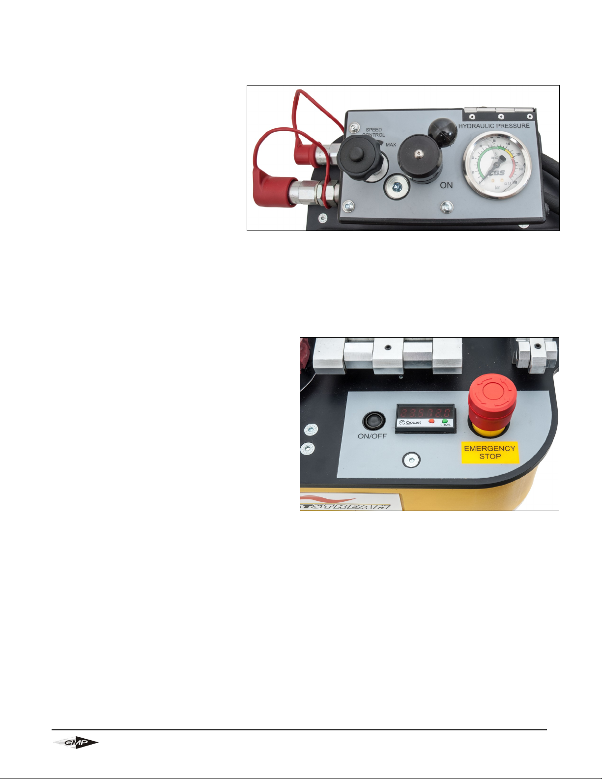
These controls are identified and their function is described below.
Speed control knob:
This valve controls the motor speed, turn
this clockwise to increase the speed of
the belts (and the cable). Turn counter
counter-clockwise to reduce the speed.
This knob can also be used to maintain
correct hydraulic pressure (driving force).
Should the pressure start to rise towards
the cut-off level the operator can reduce
the speed of the machine, this will also
reduce the hydraulic pressure.
On/Off hydraulic control lever:
This lever controls the flow of the hydraulic oil. Moving the lever to the ‘OFF’ position bypasses the oil and
stops the motor; moving the lever to the ‘ON’ position allows flow to the motor.
Emergency stop:
In the event that an emergency situation occurs and
the machine needs to be stopped and prevented
from restarting, this button will ground the spark plug
on the engine powering the hydraulic power pack.
The power pack can only be restarted once the
emergency stop has been reset, by twisting the but-
ton counter-clockwise.
Speed/Distance indicator:
This device will measure and display the distance
travelled by the cable and also the speed at which
the cable is travelling. To toggle between speed and
distance press the right-hand ‘Green’ button twice.
Pressing the right hand ‘Green’ button once shows
what is being displayed, either speed or distance.
Tacho represents speed, Count represents distance. While displaying the distance only it is possible to
reset by pressing the left hand ‘Red’ button.
Should it be necessary to replace the speed distance measuring device please contact General Machine
Products.
Page 16

Page 16
General Machine Products (KT), LLC
To install cable:
With the Jetstream setup as previously described, first ensure that the hydraulic power pack is running.
Press the ‘on/off’ button for the counter system; the screen should now power up. As described above
adjust the display to show the desired output.
Turn the hydraulic control lever to the ‘ON’ position. Turn the speed control knob clockwise towards ‘max’
until the belts begin to move. The cable will now feed through the machine and into the duct; the speed of
the install can be adjusted as required using the speed control knob.
Once a reasonable distance of cable has been installed, typically 300-600 feet (100-200m) or the hydraulic
pressure begins to increase, turn on the air feed via the handle on the ball valve. This will assist the
machine to feed the cable; verify via the pressure gauge that a reasonable pressure is being held within
the air box.
The duct route, through which the cable is to be fed, should be configured in such a way that the cable can
feed all the way along the duct and out the other end.
If there is an unexpected obstruction in the duct route the belts will see this as an increase in torque
demand and increase the drive system pressure. Assuming the pressure switch has been set at an
appropriate level, the hydraulic power pack will cut out and the belts will stop turning before they push the
cable so hard as to cause it to buckle. If (due to lack of previous knowledge of the cable characteristics)
the pressure switch has been set at a figure which is too small to push the cable the setting may be
increased. Bear in mind that this will increase the risk of the cable being damaged by buckling.
It will be necessary to be able to determine when the cable has emerged at the other end of the duct route.
A typical way of achieving this aim is to have a colleague positioned at the end of the duct run; in contact
with the main installer using a radio transmitter/receiver of some description. In this way the main installer
may be advised when the cable has completed the run, the operator can then stop the machine by turning
the hydraulic control lever to the ‘OFF’ position.
The speed control knob should then be rotated fully counter-clockwise into the minimum position.
Finally, turn the handle on the ball valve for the air feed into the ‘closed’ position. Please allow several
minutes for the air pressure in the duct to dissipate. Do not open the air box until the air pressure
gauge reads zero.
Page 17
Page 17
General Machine Products (KT), LLC
6.0 Maintenance
The JetStream Cable Blowing Machine has been designed to give reliable, trouble free service over long
periods. The machine requires no sophisticated maintenance procedures, simple common sense checks
and precautions are all that are needed.
The main source of breakdown and/or malfunction of a machine being used outdoors is contamination by
the elements, this contamination may be introduced into the machine in a number of different ways.
There may be mud, dust or other contaminants carried into the machine on the cable or duct (there may be
surface coatings of lubricants or other release type agents on the outer surfaces of the cable and duct, this
could build up on the belts and make them slip).
Contamination can also come from a muddy surface, or be splashed by vehicles when it is being used by
the roadside.
Please Note: Due to their intended use, cord seals, cable seals, duct clamps, drive belts and cable drive
belts are considered consumable items and are therefore not covered by the limited warranty.
It is convenient to consider each function of the machine in turn.
As a general rule, every time an interchangeable part is removed and replaced by a part of a different
size, shape etc. the part being removed should be thoroughly cleaned before being returned to its box.
Similarly the cavity from which it was removed can also be cleaned prior to the assembly of the
replacement part.
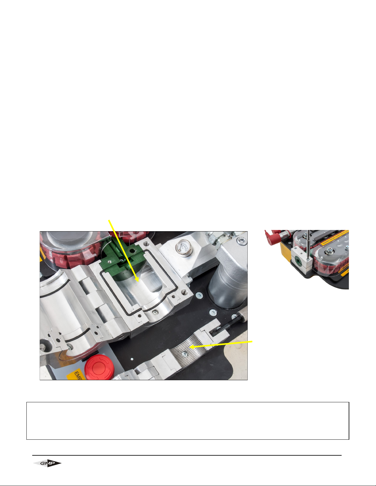
Air box parts: keep clean, build up of moisture and
dust will prevent the faces from mating, prevent the
housing seal from sealing etc. Use any traditional
workshop cleaning agent.
Cable infeed guide: keep
clean, build up of moisture
and dust may put drag on
the cable. Use any traditional
workshop cleaning agent.
Duct clamps: keep clean,
build up of moisture and dust,
particularly in the grooves,
will reduce the clamping
effect. Use traditional
workshop cleaning agent.
Page 18

Page 18
General Machine Products (KT), LLC
AIR CHAMBER
The air chamber should be inspected after each operation for seal damage or wear. Seal cord should be re-
placed if damaged and secured in position with the adhesive provided.
The cable seals should be checked for damage or wear and replaced with new ones if required. ALWAYS ap-
ply a smear of silicone grease to the seal bore and lip when installing the seal on to a cable.
ALWAYS clean out any dirt/debris in the air chamber
GENERAL
The machine should be stored in the supplied transit case when not in use. The machine should be
wiped clean after each time used.
ALWAYS ensure that there are sufficient cable seals, cord seal and cord adhesive available in the toolbox
to cover the next installation.
ALWAYS ensure that the service battery and spare battery are have sufficient charge before the cable-
blowing machine is to be used.
SERVICE CONNECTIONS
CHECK the condition of the hydraulic hoses each time used and replace if worn or damaged.
CHECK the condition of the emergency stop cable each time used and replace if worn or damaged.
CHECK the condition of the compressed air hose each time and replace if worn or damaged.
The machine should be returned to GMP (or an approved service agent) after every 1000 hours use (or at
intervals of 12 months) for a major service.
Page 19
Page 19
General Machine Products (KT), LLC
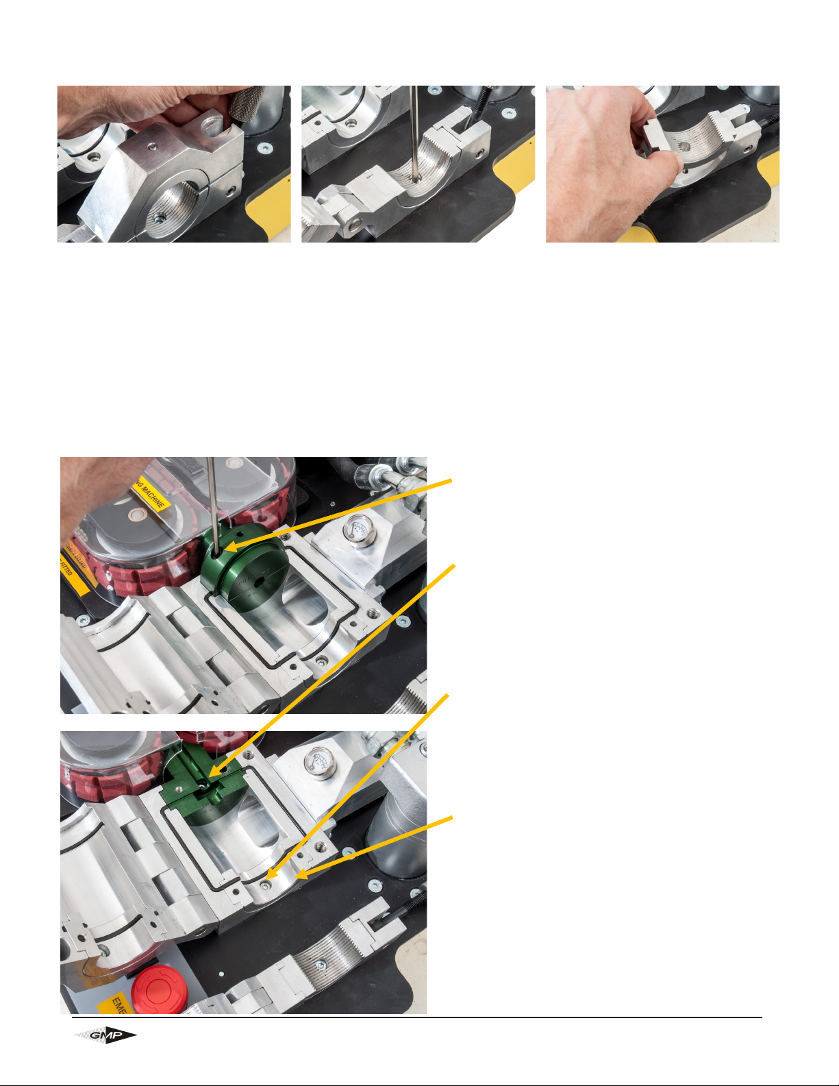
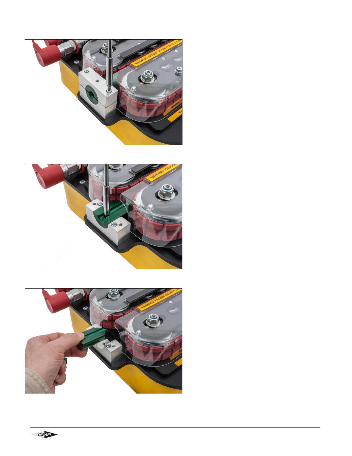
7.0 Procedure for changing duct clamps
8.0 Procedure for changing cable collets and duct seals in
the air box
Undo the locking screw and
rotate open the duct clamp
housing
Loosen and remove the screw
(1 per insert). Do not lose this
screw; it will be needed for the
replacement clamp.
Remove the duct clamp
Repeat the process for the duct clamp in the other housing half.
To fit the new duct clamp, reverse the disassembly procedure.
For cable collets loosen the screw in the upper
insert. Remove the upper insert from the lower
insert.
Now loosen and remove the screw in the lower
cable seal insert. (Do not lose this screw, it will
be needed for the replacement insert). Remove the lower cable collet.
For duct seals loosen and remove the screw.
(Do not lose this screw, it will be needed for the
replacement insert)
Remove the duct seal
Repeat the process for the duct seal in the other
box half
To fit the new inserts, reverse the disassembly procedure.
Page 20
Page 20
General Machine Products (KT), LLC
9.0 Procedure for changing cable guide inserts in infeed
Loosen and remove the screws securing the upper guide housing
Loosen and remove the screw securing the cable guide insert into the housing
Remove and replace the cable guide insert.
Page 21
Page 21
General Machine Products (KT), LLC
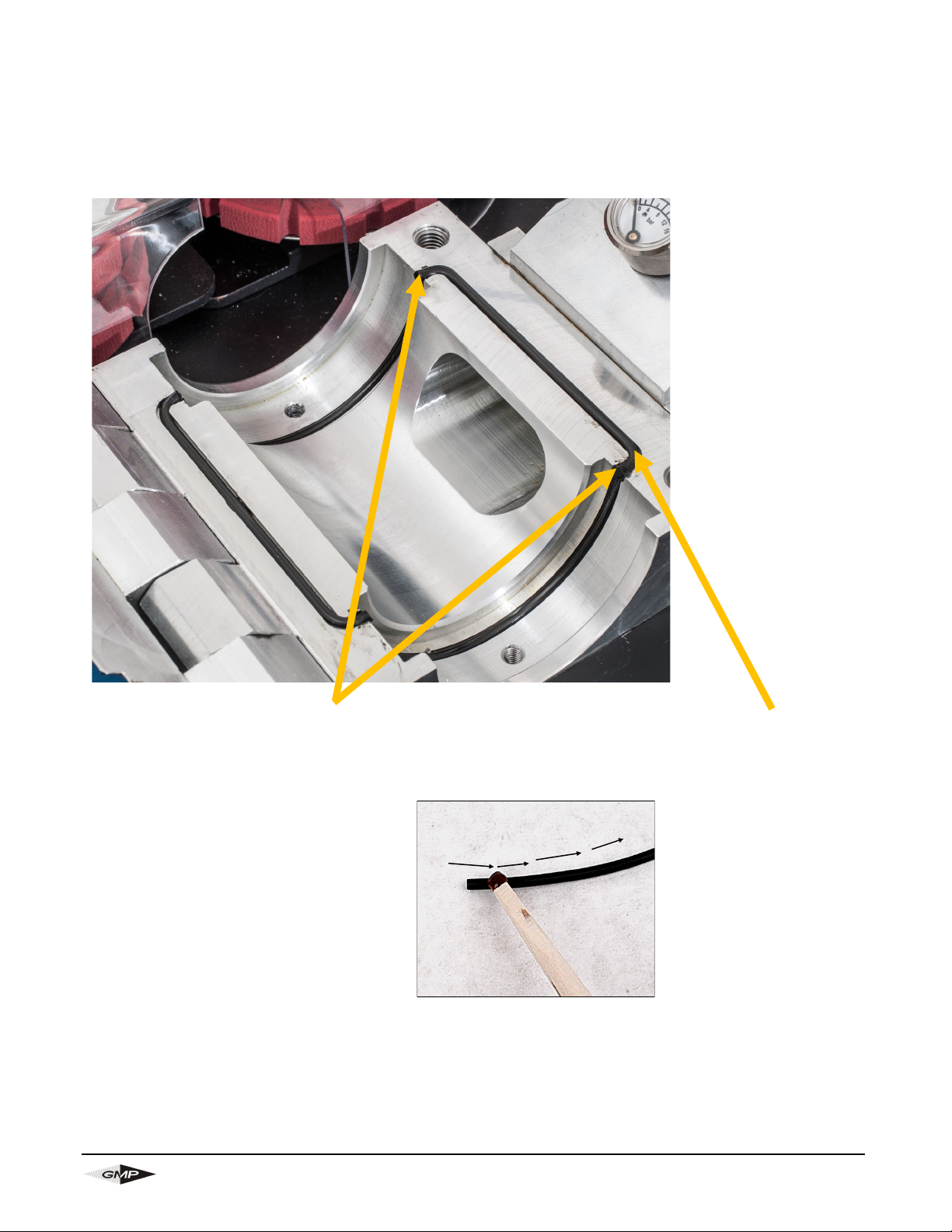
10.0 Procedure for replacing the air box housing seal
Take a length of ø2.5mm sealing
material, line it up at the end of the
upper seal groove, and cut it off a
little longer than is necessary
Trim the seal with the end of the
groove each end. Take care not to
damage the seating diameter for the
cable seal and the duct seal. Take
care to make the cut accurately in line
with the end of the groove, the cable
seal and duct seal need to make an
effective seal against the ends of the
housing seal.
Place the pre-cut length
in the groove, with some
of the excess length
overhanging each end of
the groove
Repeat the procedure for the lower seal groove and the collet seal grooves in the air box lower and lid as
indicated.
Apply a thin coat of 3M Rubber
and Gasket Adhesive to the top
of the cut sealing material
Spread adhesive along one
side of cord.
Page 22
Page 22
General Machine Products (KT), LLC
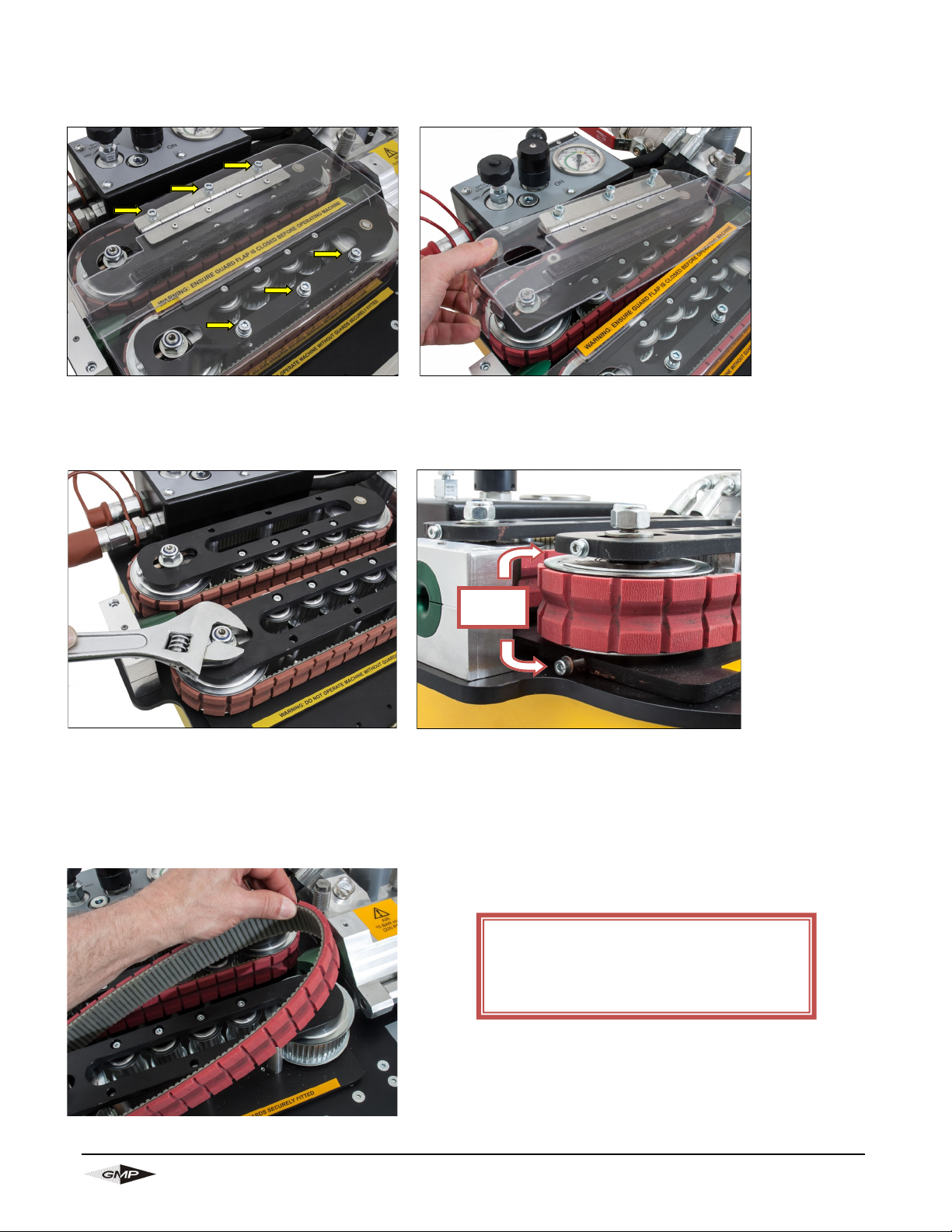
11.0 Procedure for changing the cable drive belts
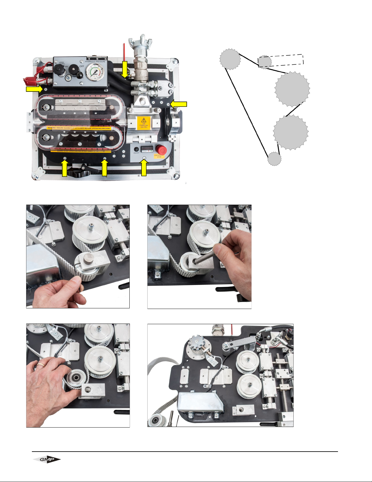
Loosen the tension nut on the large idler pulley. Loosen the tension screws in both the upper and
lower drive plate. This should then provide enough slack at the drive pulley side to remove the belt.
Remove the 6 screws retaining the belt guards and remove the guards.
Tension
Screws
Always remove the belt from the drive pulley
side first. Replace the drive belt by reversing
the disassembly procedure.
NOTE: NEVER POWER THE MACHINE
UP OR RUN WITH THE GUARDS
REMOVED. DOING SO MAY RESULT
IN INJURY TO THE OPERATOR.
Page 23
Page 23
General Machine Products (KT), LLC
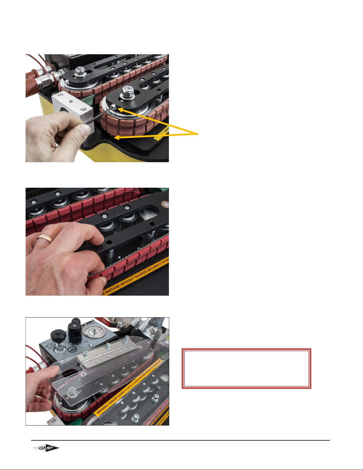
12.0 Procedure for tensioning the drive belts
Place the new belt in position as in section 11.0.
Tighten the tension screws evenly in the upper and
lower drive plates with the tension nut slackened off
slightly. This will begin to tighten the belt. Once the
appropriate tension is reached, tighten the tension
nut.
Check the belt tension, this should be approximately
1/4" of slack, if necessary loosen the tension nut
and re-adjust the tension screws until the correct
tension is achieved, check that the tension nut is
tight upon completion.
(Note: The belt tension should be checked
periodically)
Replace the drive belt guards and the 6 retaining
screws.
NOTE: NEVER POWER THE MACHINE
UP OR RUN WITH THE GUARDS
REMOVED. DOING SO MAY RESULT
IN INJURY TO THE OPERATOR.
Tension screws
Page 24
Page 24
General Machine Products (KT), LLC
13.0 Procedure for checking and replacing the motor drive
belt
Loosen (6) screws indicated to permit access.
Page 25
Page 25
General Machine Products (KT), LLC
14.0 Procedure to set the Pressure Switch
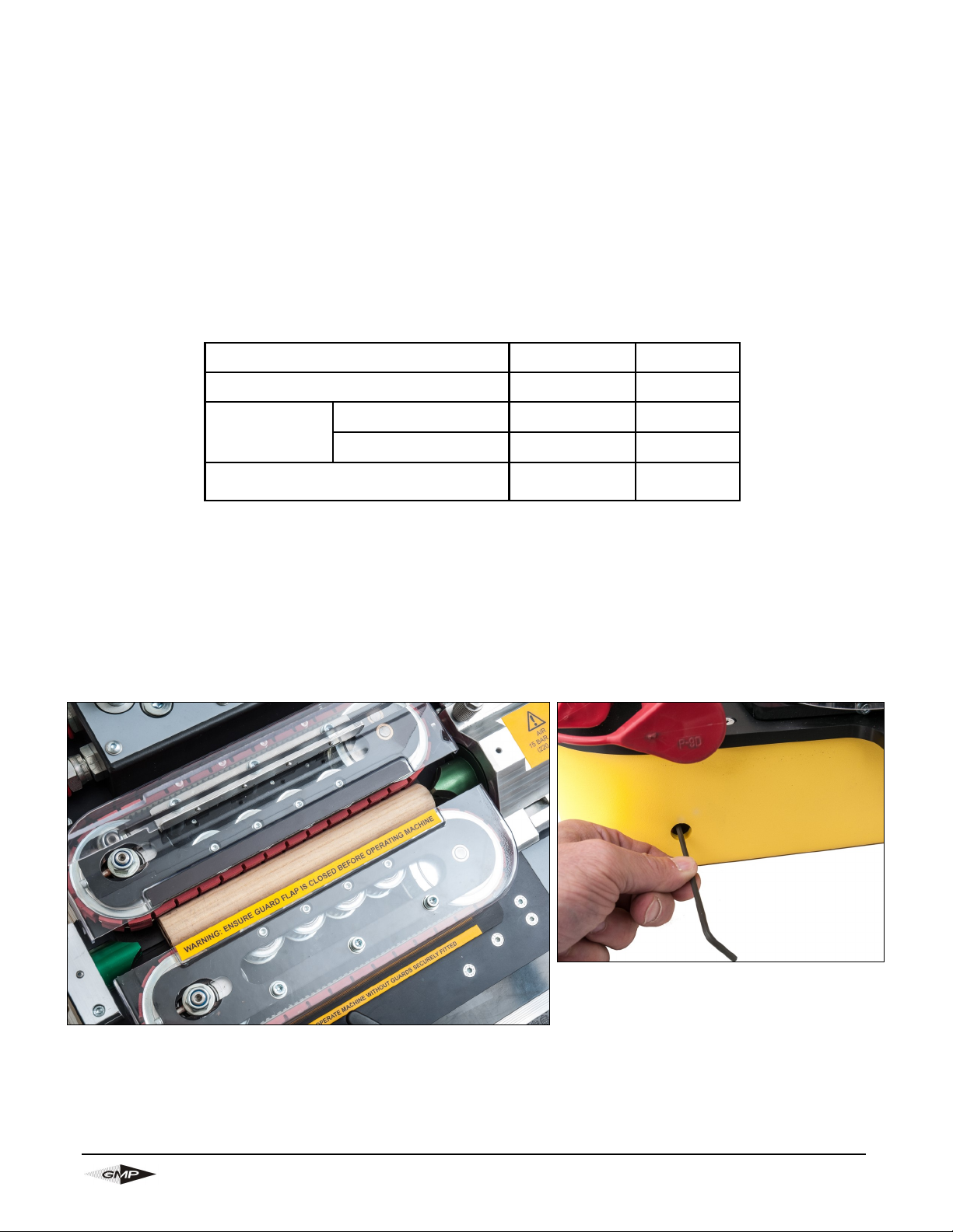
• Clamp a piece of 1 to 1 1/4" O.D. dowel x 10" long between the drive belts so it butts up to the air chamber
mounted collets (in effect placing the motors in stall mode).
• Connect the electric lead to the power pack and blowing machine.
• Ensure the speed control knob is set to minimum (turned fully counter-clockwise).
• Press the on/off button (to turn the electric’s on).
• Turn the pressure switch adjusting screw fully in using the 1/8” long series hex key through the hole in
the side of the base.
• Start the power pack.
• Turn the hydraulic on/off valve to ‘on’ position.
• Turn the speed control knob towards ‘max’ (clockwise) until the pressure gauge reads the required
pressure switch setting.
• Turn the pressure switch adjusting screw slowly out until the power pack stops.
• Turn the speed control knob to minimum (turned fully counter-clockwise).
• After 5 seconds has elapsed restart the power pack and turn the speed control knob slowly towards ‘max’,
observe at what pressure the power pack stops, repeat the procedure and fine adjust the pressure switch
adjusting screw until the correct setting is achieved..
Pressure switch adjustment
access hole found on
side of unit
Maximum operating pressure: 1015 psi 70 Bar
Recommended flow: 4 gal/min (US) 15 l/min
Pressure
switch setting:
12-20mm OD Cable 1015 psi 70 Bar
4-12mm OD Cable 725 psi 50 Bar
Initial starting pressure:
(if greater the set-up needs checking)
290-435 psi 20-30 Bar
Page 26
Page 26
General Machine Products (KT), LLC
• Clamp a piece of 1 to 1 1/4" O.D. dowel x 10" long between the drive belts and through the air box so it
butts up to the duct clamp collets. The duct clamp collets must be smaller than the dowel/round bar (in
effect placing the motors in stall mode). (see page 25)
• Ensure that the electronics are turned off or the electric lead to the power pack is unpluged
• Ensure the speed control knob is set to minimum (turned fully counter-clockwise).
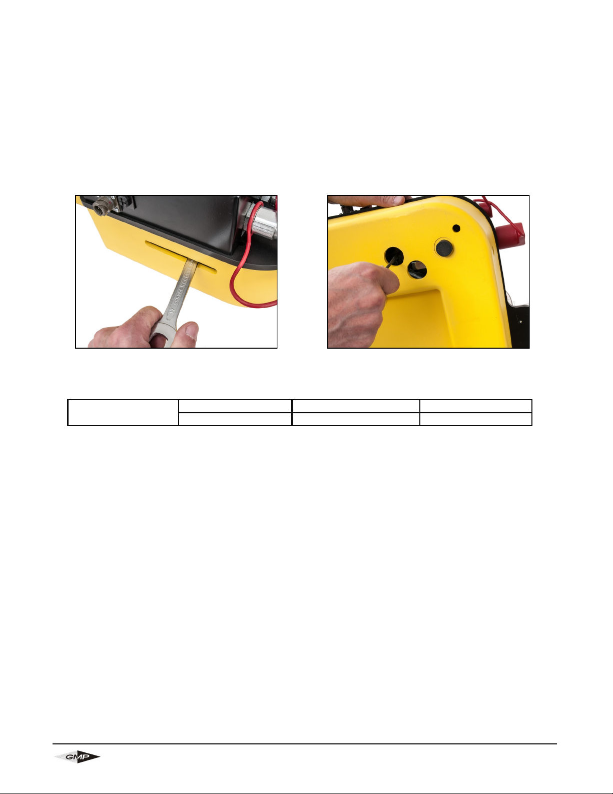
• Loosen the lock nut on pressure relief valve by using a 1/2" open ended wrench in the slot at back of
the base. (see below)
15.0 Procedure to set the Pressure Relief Valve
• Using a 5/32" long series hex key adjust the pressure as required. Turn screw counterclockwise to re-
duce the pressure and clockwise to increase the pressure.
• Tighten pressure relief valve lock nut via the slot in the back of the machine.
• Check pressure setting after tightening the lock nut and repeat if not correct.
Loosen lock nut on pressure relief valve
Using a 5/32" long series hex key adjust the pressure
Pressure Relief
Valve setting
12-20mm OD Cable 1160 psi 80 Bar
4-12mm OD Cable 870 psi 60 Bar
Page 27

Page 27
General Machine Products (KT), LLC
16.0 Monthly service – check list
This section is included in the manual for your convenience, there follows a list of suggested checks, it is
recommended that these checks be carried out on a regular basis, depending on use. Monthly checks are
convenient; a few minutes can be set aside on the same day of each month to complete these simple
checks. The next section of this manual is an empty table, the dates when these checks and all other
service and repair jobs are completed can be entered into the spaces provided in this table. This will give
the user a record of what service has been carried out and when.
1. Check the tool box, ensure all tools and interchangeable parts are present, clean and ready for use.
2. Remove the clear belt guards, clean the outside of the machine and replace.
3. Ensure the slide mechanism operates smoothly, lubricate if necessary with a dry film lubricant.
4. Clean the exposed threads on the swing bolts on the air box and duct clamp assembly together.
Add a smear of grease/oil to prevent build up of surface corrosion and to ensure smooth operation of
the thumb nuts.
5. Check the cable drive belt tension.
Page 28
Page 28
General Machine Products (KT), LLC
Service no Date
Carried out
by
Record of service/repair
17.0 SERVICE HISTORY RECORD
Page 29
Page 29
General Machine Products (KT), LLC
18.0 Duct Integrity and Duct Lubrication
This is entirely the responsibility of the operator.
To be sure that the duct into which the cable is to be inserted is installed appropriately, it is recommended
that its integrity and lubrication be checked.
Check that the duct is:
1. Not blocked
2. Not squashed
3. Continuous (i.e. it has not been fractured somewhere along its route and the fractured ends separated)
4. Also check that any joints are pressure tight
5. Finally check that the duct is appropriately lubricated.
The easiest and most straightforward way to complete these checks is to set the machine up for a normal
cable insertion but fit a seal plug in place of the cable. The duct can then be pressurised without running
the belt drive.
CAUTION: ANY OBJECT INADVERTENTLY LEFT IN THE DUCT DURING THE DUCT LAYING
MAY BE EXPELLED FROM THE END OF THE DUCT WITH HIGH FORCE AND VELOCITY. IT
IS IMPERATIVE THAT NO PERSONNEL BE IN THE VICINITY OF THE END OF THE DUCT
AND THAT A SUITABLE DEVICE IS FITTED TO THE END OF THE DUCT TO ARREST ANY
EXPELLED OBJECT.
The checks listed at 1-4 (inclusive) above may all be carried out at the same time using one check. The
procedure is outlined below. Set up the air box and duct clamp with plug inserted as shown below and
close duct clamp. Tighten the thumbnut. Close the airbox lid and tighten the (2) thumbnuts.
Page 30
Page 30
General Machine Products (KT), LLC
The air box and duct clamp are now set up to blow air through the duct. Connect the air as for normal
blowing. Make sure there are personnel at the other end of the duct run, and that they are aware that the
air is to be turned on. Make sure that a suitable device is fitted (a catcher is available from General
Machine Products; speak to our sales department for details) to help avoid injury should any object be
expelled from the far end of the duct.
The far end of the duct run should be monitored; air should be leaving the duct under reasonable pressure.
The minimum pressure required will vary with the length of duct in the run, the friction characteristics of the
duct and the cable and the lubrication being used. Bear in mind that if the duct run is of considerable
distance, it may take a few minutes for the air to reach the far end of the duct.
If after waiting a suitable time there is no air leaving the far end of the duct, this would indicate that there is
a blockage or similar obstruction in the duct run, or, that the duct is fractured. In either case the fault must
be corrected before any attempt is made to blow cable down the duct.
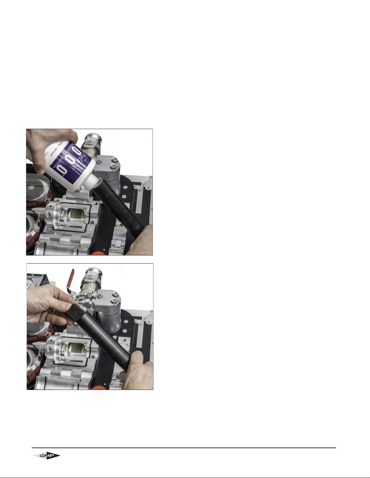
Once the duct integrity has been confirmed by the method outlined above, the duct may be lubricated.
Open the air box and duct clamp assembly, withdraw the duct
and raise it so that the lubricant will pour into it easily and not
overflow from the top. Pour lubricant of recommended quality
and quantity down the duct.
Insert a suitable foam plug into the duct and put the duct back
into the air box and duct clamp. Tighten the thumbnuts of the
duct clamp and (2) thumbnuts of the airbox. The air box and
duct clamp assembly are now set up to blow the foam plug
through the duct, the foam plug will help to deposit an even
coating of lubricant to the inside walls of the duct. Connect the
air as for normal blowing. Make sure there are personnel at
the other end of the duct run, and that they are aware that the
air is to be turned on. Make sure that a suitable device is fitted
(a catcher is available from General Machine Products; speak
to our sales department for details) to help avoid injury should
any object be expelled from the far end of the duct. When the
foam plug has been expelled from the far end of the duct run,
cable can be installed into the duct.
Note: when the air is turned off, after checking the duct
integrity and sending the foam plug down the duct to spread
the lubricant. It may take some time for the pressure in the duct to dissipate, time must be allowed for the
pressure to fall back to low levels before the airbox can be opened.
Page 31

Page 31
General Machine Products (KT), LLC
19.0 Trouble Shooting Guide
AT THE POINT OF STARTING A CABLE INSTALLATION THE HYDRAULIC PRESSURE WILL BE
BETWEEN 290-435 PSI (20-30 BAR). IF HIGHER VALUES ARE REACHED DO NOT CONTINUE, SEE
SECTION ‘RUNS AT HIGHER THAN EXPECTED PRESSURE’ TO RECTIFY PROBLEM BEFORE
COMMENCING CABLE INSTALLATION.
WILL NOT ACHIEVE MAX PRESSURE
• ON/OFF control valve not open fully
• Faulty power pack (check performance output) See Jetstream Pressure Test on page 25
• Cable clamping force not correctly set (Allowing belt slip)
• Worn belts due to cable slip
• Excessive lubrication blowback (on to belts causing belt slip)
RUNS AT HIGHER THEN EXPECTED PRESSURE
• Excessive clamping force on cable.
• Seized bearings
• Over tightening of belt tensioning screws
• Cable drum not rotating freely on shaft
• Poor duct and installation causing high cable frictions
• Insufficient out-put from compressor (See recommendations for duct diameter on page 8)
• Incorrect seal/collet fitted
• Dirt/debris in belt drive
PROVISIONAL BELT ROTATION TEST:- With Hydraulic power pack running and without cable, revolve the
Drive Belts and monitor the minimum hydraulic pressure required. This should be around 220-360 psi (15-
25) Bar as a benchmark.
CABLE BLOWING MACHINE STOPS SUDDENLY DURING CABLE INSTALLATION
• Maximum Hydraulic pressure achieved
• Obstacle in duct installation
• Power Pack out of fuel
• Emergency button pressed
• Damaged lead between Power Pack and blowing machine
ENGINE DOES NOT STOP AT MAX PRESSURE
• Emergency lead not connected
• Electrical display not switched on
• Batteries low on power
• Fuse blown in control panel
• Incorrect pressure switch setting
EXCESSIVE AIR LEAKAGE FROM AIR CHAMBER
• Damaged cord seal
• Cable seals worn, incorrect size, wrong way round
• Incorrect cable collets
COUNTER NOT READING OR GIVING INCORRECT READINGS
• Batteries low on power
• Counter program has been changed – clear program and re-program as described on page 39
Page 32
Page 32
General Machine Products (KT), LLC
20.0 Battery Replacement
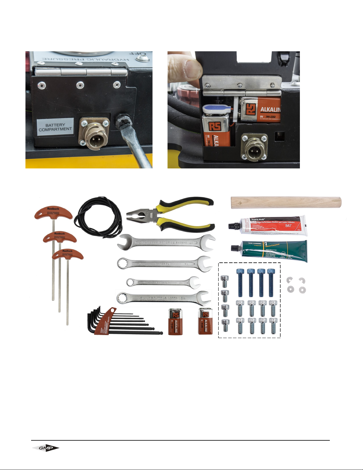
The batteries are located in the battery compartment at the rear of the hydraulic control panel
21.0 Toolkit Contents
22.0 Spares
Cable Drive Belt: 33772 (2 req)
Motor Drive Belt: 33770
Install 9 volt lithium batteries for longest service life
33958
89588
32411
30069
89150
89148
34075
33816
34757
89146
33812
33813
33814
32617
34444
36292
Page 33
Page 33
General Machine Products (KT), LLC
Let our "Cable Blowing Experts" tailor your configuration. Call 1-800-345-6009 for any questions.
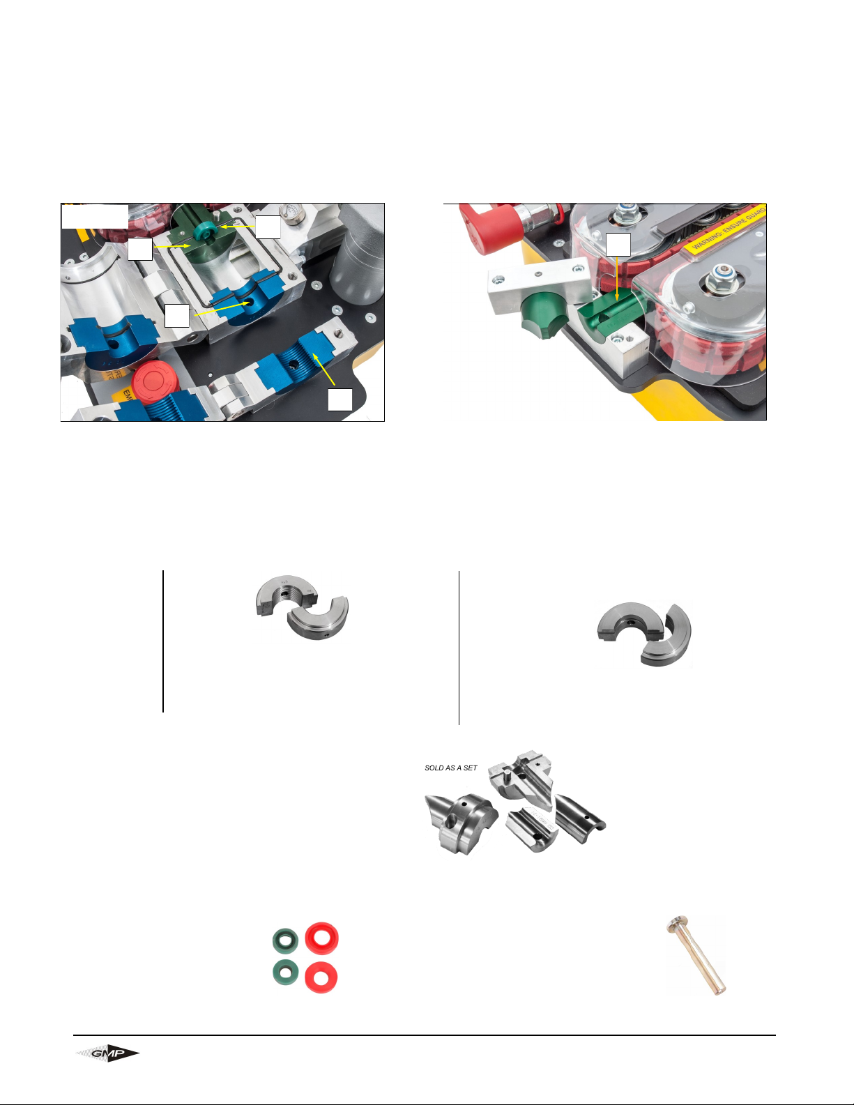
Locator Description Qty needed
(A) Duct Clamp 1 (2 halves) In order to configure your JetStream to work
with your specific cable requirements you
must select items below that match your
duct and cable size. Additional duct clamp
and duct seal sizes are available upon
request.
(B) Duct Seal 1 (2 halves)
(C) Cable Collet 1 (2 halves)
(D) Cable Guide Insert 1 (2 halves)
(E) Cable Seals 1 (pkg of 10)
(F) Cable Seal Plug 1 unit
How to configure your JetStream
Exit Side
B
C
E
A
How to specify the collets and seals to match your cable and duct size.
Note: Cables 6-20mm utilize the standard belts (P/N 33772). Cables 4-16mm require optional belts (P/N 89214).
1. Select one (1) Duct Clamp (locator A) that represents the size of the duct that you're using.
2. Select one (1) Duct Seal (locator B) that represents the size of the duct that you're using.
3. Select the Cable Collet (locator C) that matches the cable’s size.
4. Select the cable guide insert (Locator D) that matches the cable’s size.
5. Select the Cable Seals (locator E) that matches your cable’s size.
6. Select one (1) Cable Seal Plug (locator F) that matches your cable size.
(Loc A) DUCT CLAMPS (O.D. Controlled)
Metric Imperial
P/N Size (SDR) P/N Size
89960
3/4"
89964 12mm
89961 1" 89959 12.7mm
89962 1.25" 89965 16mm
89963 1.50" 89966 18mm
89958 22mm
89967 25mm
89968 32mm
89969 40mm
89970 50mm
D
APPENDIX 1
(Loc F) CABLE SEAL PLUGS (6-28mm)
89125 6-7.5mm (.23 - .29")
89126 7.5-9mm (.29 - .35")
89127 9-10.5mm (.35 - .41")
89128 10.5-12mm (.41 - .47")
89129 12-14mm (.47 - .55")
89130 14-16mm (.55 - .63")
89131 16-18mm (.63 - .71")
89132 18-20mm (.71 - .79")
(Loc E) CABLE SEALS (6-28mm)
89085 6-7.5mm (.23 - .29") 10/PK
89086 7.5-9mm (.29 - .35") 10/PK
89087 9-10.5mm (.35 - .41") 10/PK
89088 10.5-12mm (.41 - .47") 10/PK
89093 12-14mm (.47 - .55") 10/PK
89094 14-16mm (.55 - .63") 10/PK
89095 16-18mm (.63 - .71") 10/PK
89096 18-20mm (.71 - .79") 10/PK
ID COLOR CODES
GREEN 1 LINE
GREEN 2 LINES
PURPLE 1 LINE
PURPLE 2 LINES
SILVER 1 LINE
SILVER 2 LINES
GOLD 1 LINE
GOLD 2 LINES
(Loc B) DUCT SEALS (O.D. Controlled)
Metric Imperial
P/N Size (SDR) P/N Size Replacement O Ring Seal (5 pack)
89972
3/4” *
89976 12mm 89552
89973
1" *
89983 12.7mm 89552
89974
1.25" *
89977 16mm 89554
89975
1.50" *
89978 18mm 89558
89971 22mm 89561
89979
25mm *
89980
32mm *
89981
40mm *
89982
50mm *
*
O Ring Seals Not Required
SOLD AS A SET
(Loc C & D) CABLE COLLETS ASSEMBLIES
89890 4-6 MM (.16 - 23")
89891 6-9 MM (.23 - .35")
89892 9-12 MM (.35 - .47")
89893 12-16 MM (.47 - .63")
89894 16-20 MM (.63 - .79")
Page 34

Page 34
General Machine Products (KT), LLC
APPENDIX 2
Crouzet Counter Programming
Programming Parameters
• Press and hold both ◄ and ► buttons.
After 5 seconds ‘ProG’ will be displayed. Releasing the buttons will display ‘no’
• Press ►
‘Yes’ is displayed
• Hold ◄ and press ►
‘InPol’ is displayed
• Press ► until ‘nPn’ is displayed
• Hold ◄ and press ►
‘Filter’ is displayed
• Press ► until ‘oFF’ is displayed
• Hold ◄ and press ►
‘InPut’ is displayed
• Press ► until ‘Cnt.dir’ is displayed
• Hold ◄ and press ►
‘FAc.Cnt’ is displayed
• Press ◄
• Enter value 00.0200 for meters, 00.0656 for feet
Use ◄ to move to next digit
Use ► to increment digit (this instruction applies to all following number inputs)
• Hold ◄ and press ►
‘diV.Cnt’ is displayed
• Press ◄
• Enter value 01.0000
• Hold ◄ and press ►
‘dP.Cnt’ is displayed
• Press ► until ‘0’ is displayed
• Hold ◄ and press ►
‘rES.Cnt’ is displayed
• Press ► until ‘MAnrE’ is displayed
• Hold ◄ and press ►
‘FAc.tAc’ is displayed
• Press ◄
• Enter value 00.0200 for meters, 00.0656 for feet
• Hold ◄ and press ►
‘diV.tAc’ is displayed
• Press ◄
• Enter value 01.0000
• Hold ◄ and press ►
‘dP.tAc’ is displayed
• Press ► until ‘0’ is displayed
• Hold ◄ and press ►
‘disPm’ is displayed
• Press ► until ‘Min-1’ is displayed
• Hold ◄ and press ►
‘Wait0’ is displayed
Page 35

Page 35
General Machine Products (KT), LLC
•Press ◄
•Enter value 01.0
•Hold ◄ and press ►
‘EndPro’ is displayed
•Press ► until ‘YES’ is displayed
•Hold ◄ and press ►
Programming completed
OR
•Press ► until ‘no’ is displayed
•Hold ◄ and press ►
Programming mode restarted
APPENDIX 2 (con’t)
Page 36

Page 36
General Machine Products (KT), LLC
General Machine Products (KT), LLC • 3111 Old Lincoln Hwy • Trevose, PA 19053 • USA
TEL: +1-215-357-5500 • FAX: +1-215-357-6216 • Web: www.gmptools.com
 Loading...