

Page 1
USER'S GUIDE
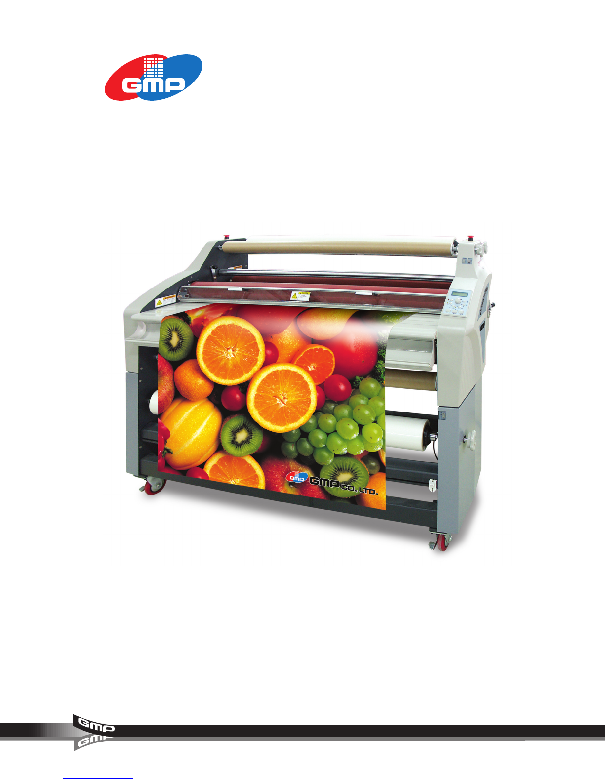
EXCELMASTER-1600
Before operating the unit, please read this manual thoroughly and retain it for future reference.
Page 2

TABLE OF CONTENT
Cover 1
Table of Content 2
Important Safety Instructions 3
Specifications 4
Pre-Installation 5
Installation 6
Control Guide 7
Power ON/ OFF 7
Control Panel Display 7
Control Panel 7
Rewinder Selection Switch 8
Upper Rewinder Direction Switch 9
Lower Rewinder Direction Switch 9
Rear Control Switch 9
Foot SW Enable 9
Features Guide
E-Stop 10
Safety Shield Interlock Latch 10
Safety Shield 10
Feed Table 10
Heat Rollers 10
Pull Rollers 10
Roller Handle 11
Idler Bar 11
Chill Idler 11
Cooling Fans 11
Film Shaft 11
Lower Shaft Lock 11
Rewind Shaft 12
Rewind Tube 12
Unwind/ Rewind Tension 12
Core Adaptors 12
Rewind Adaptors 12
Rear Table 12
Rear Slitter 12
Film Web 12
Nip Point 12
Foot Switch 12
Print Unwind Basket 12
Options 12
Separator Bar 12
Rewind Kit 12
Film Loading and Threading 13
Load a Roll of Film 13
Loading Top Thermal Film 14
Loading Top PSA Film 14
Loading Top Mount Adhesive 15
Loading Bottom Thermal Film 15
Loading Bottom PSA Film 16
Loading Bottom Mount Adhesive 16
Threading Card Procedure 17
Start Laminating 18
Tacking New Film To Existing Film 19
To Unweb The Laminator 20
Clearing A Film Jam 20
Applications 21
Pre-Coating Boards 21
Using Rear Rollers 21
Mounting Pre-Coated Boards 21
Single Sided Lamination 22
Creating a Decal 22
Mounting a Decal 22
PSA Encapsulation 23
Thermal Encapsulation 23
Micronex 23
The Art Of Lamination 24
Basic Rules 24
Film Tension 24
Heat 25
Output 25
Maintenance 26
Troubleshooting Guide 27
2
Page 3
IMPORTANT SAFETY INSTRUCTIONS
g
y
q
q
q
g
q
y
g
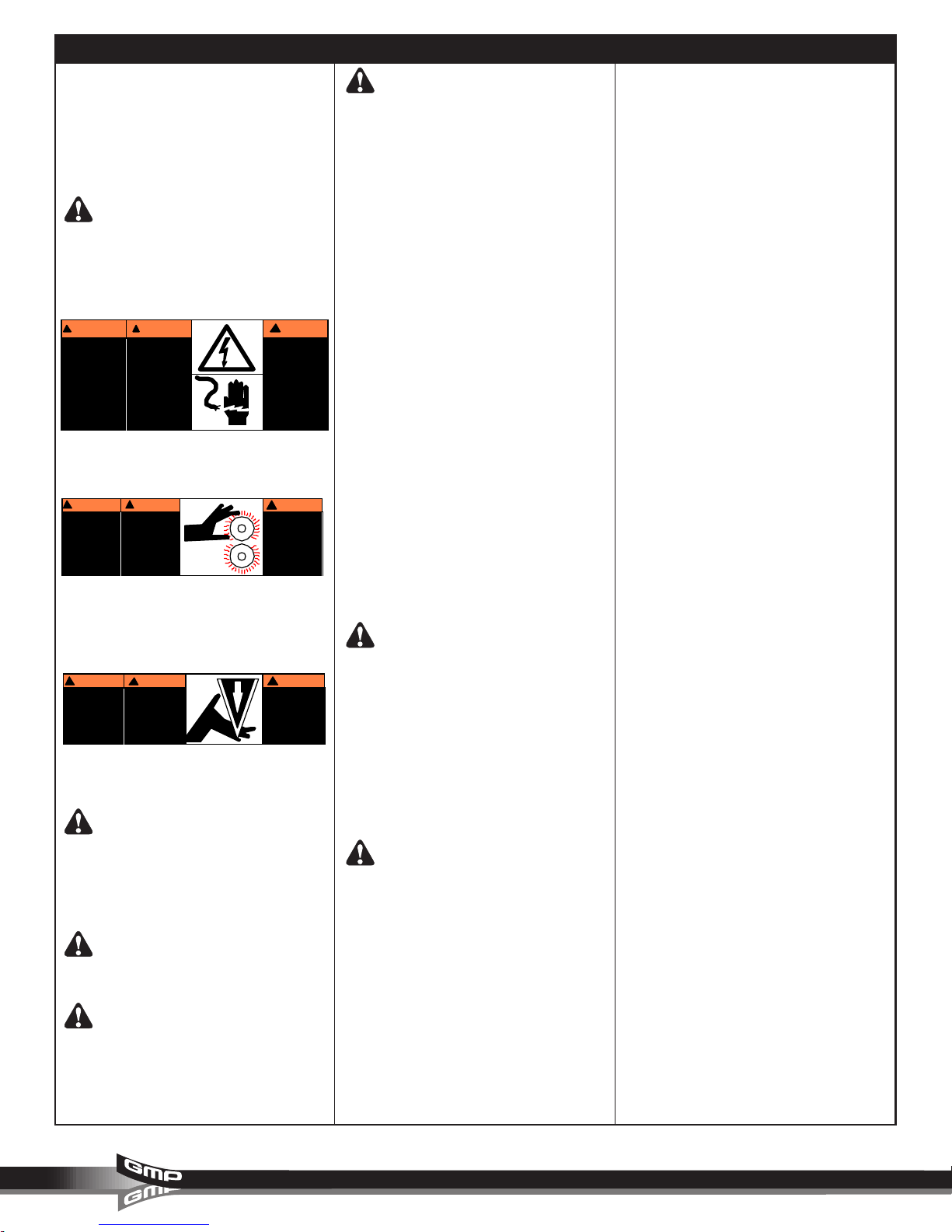
YOUR SAFETY AS WELL AS THE SAFETY OF
OTHERS IS IMPORTANT T O GBC. IN THIS
INSTRUCTION MANUAL AND ON THE
PRODUCT , YOU WILL FIND IMPORT ANT
SAFETY MESSAGES REGARDING THE
PRODUCT . READ THESE MESSAGES
CAREFULL Y . READ ALL OF THE INSTRUCTIONS AND SAVE THESE INSTRUCTIONS FOR
LATER USE.
THE SAFETY ALERT SYMBOL PRE-
CEDES EACH SAFETY MESSAGE IN
THIS INSTRUCTION MANUAL. THE SYMBOL
INDICATES A POTENTIAL PERSONAL
SAFETY HAZARD TO YOU OR OTHERS, AS
WELL AS PRODUCT OR PROPERTY DAMAGE.
THE FOLLOWING WARNINGS ARE FOUND
UPON THIS PRODUCT .
!
ADVERTENCIA
o de choque
Ries
eléctrico
No abra:
Adent r o no ha
piezas r epar ables
por el us uar io.
Mantenimiento
solament e por
personal
calificado
ATTE N TI ON
!
Ris
ue de
secousse
ue.
électri
Ne pas ouvrir.
Pas de pièces
réparables par
l'utilisateur.
Entretien
seulement par
personnel
ualifié.
THIS SAFETY MESSAGE MEANS THAT YOU
COULD BE SERIOUSL Y HURT OR KILLED IF
YOU OPEN THE PRODUCT AND EXPOSE
YOURSELF TO HAZARDOUS VOLT AGE.
!
ADVERTENCIA
RODILLOS
CALIENTES.
PUNT O DE
PINCHAMIENTO.
Mantener manos
ropa a d is t anc i a.
!
ATTENTION
ROULEAUX
CHAUDS.
POINT DE
PINCEMENT.
Tenir mains et
vêtements à l'écart.
THIS SAFETY MESSAGE MEANS THAT YOU
COULD BE BURNED AND YOUR FINGERS AND
HANDS COULD BE TRAPPED AND CRUSHED
IN THE HOT ROLLERS. CLOTHING, JEWELRY
AND LONG HAIR COULD BE CAUGHT IN THE
ROLLERS AND PULL YOU INTO THEM.
!
ADVERTENCIA
NAVAJA FILOSA.
Mant ener m a nos y
dedos a dist anc ia.
!
ATTENTION
LAME COUPANT E.
Tenir mains et
doigts à l'écart.
THIS SAFETY MESSAGE MEANS THAT YOU
COULD CUT YOURSELF IF YOU ARE NOT
CAREFUL.
WARNING: THE SAFETY ALERT
SYMBOL PRECEDES EACH SAFETY
MESSAGE IN THIS INSTRUCTION MANUAL.
THE SYMBOL INDICATES A POTENTIAL
PERSONAL SAFETY HAZARD TO YOU OR
OTHERS, AS WELL AS PRODUCT OR
PROPERTY DAMAGE.
WARNING: DO NOT A TTEMPT TO
SERVICE OR REPAIR THE LAMINATOR.
WARNING: DO NOT CONNECT THE
LAMINATOR TO AN ELECTRICAL
SUPPLY OR A TTEMPT T O OPERA TE THE
LAMINAT OR UNTIL YOU HAVE COMPLETELY
READ THESE INSTRUCTIONS. MAINTAIN
THESE INSTRUCTIONS IN A CONVENIENT
LOCATION FOR FUTURE REFERENCE.
!
WARNING
Elect ric al s hock
hazard.
Do not open.
No user
serviceable
part s in side.
to
Refer servicin
ualified s er v ice
personnel.
!
CAUTION
HOT ROLLS.
PINCH POINT.
Keep hands an d
clot hin
away.
!
CAUTION
SHARP BLADE.
Keep hands and
clot hing aw ay .
INJURY , THE FOLLOWING SAFETY
PRECAUTIONS MUST BE OBSERVED IN THE
INSTALLA TION AND USE OF THE LAMINA T OR.
General
Keep hands, long hair, loose clothing, and articles such
as necklaces or ties away from the front of the heat
and pull rollers to avoid entanglement and entrapment.
The heat rollers can reach temperatures over 300° F.
Avoid contact with the heat rollers during operation or
shortly after power has been removed from the
laminator.
Keep hands and fingers away from the path of the
sharp film cutter blade located at the film exit.
Do not use the laminator for other than its intended
purpose.
Avoid moving the laminator on uneven floor surfaces.
Never tilt the laminator.
Do not defeat or remove electrical and mechanical
safety equipment such as interlocks, shields and
guards.
Do not insert objects unsuitable for lamination or
expose the equipment to liquids.
Electrical
The laminator should be connected only to a source of
power as indicated in these instructions and on the
serial plate located on the rear of the laminator.
Contact an electrician should the attachment plug
provided with the laminator not match the receptacles
at your location.
CAUTION: The receptacle must be
located near the equipment and
easily accessible.
Do not operate the laminator with a damaged power
supply cord or attachment plug, upon occurrence of a
malfunction, or after the laminator has been damaged.
Contact GMP’s Technical Service Department or your
dealer/distributor for assistance.
Service
Perform only the routine maintenance procedures
referred to in these instructions.
WARNING: Do not attempt to service
or repair the laminator.
Disconnect the plug from the receptacle and contact
GMP's Technical Department or your dealer/distributor
when one or more of the following has occurred.
- The power supply cord or attachment plug is
damaged.
- Liquid has been spilled into the laminator.
- The laminator is malfunctioning after being
mishandled.
- The laminator does not operate as described in
these instructions.
WARRANTY
GMP warrants to the original purchaser for a
period of ninety (90) days after installation that
this laminator is free from defects in workmanship and material under normal use and service.
GMP's obligation under this warranty is limited to
replacement or repair, at GMP's option, of any
part found defective by GMP without charge for
material or labor.
This warranty is in lieu of all other warranties
expressed or implied. WARRANTIES OF
MERCHANTABILITY OR FITNESS FOR A
PARTICULAR PURPOSE ARE EXPRESSL Y
EXCLUDED. Any representations or promises
inconsistent with, or in addition to, this warranty
are unauthorized and shall not be binding upon
GMP. In no event shall GMP be liable for any
special, incidental or consequential damages,
whether or not foreseeable.
This warranty shall be void if the product has
been misused; mishandled; damaged by
negligence, by accident, during shipment, or
due to exposure to extreme conditions;
repaired, altered, moved, or installed by anyone
other than GMP or its authorized agents; or if
incompatible film was used. GMP's obligation
under this warranty does not include routine
maintenance, cleaning, adjustment, normal
cosmetic or mechanical wear, nor freight
charges.
Without limiting the generality of the previous
paragraph, GMP's obligation under this
warranty does not include:
• damage to the pressure rollers or pull rollers
caused by knives, razors, or other sharp
tool; by any object falling into the working
area of the laminator; or by cleaning the
rollers with solutions or materials that harm
their surfaces;
• damage to Lucite panels or manometer glass
caused by mechanical action or by cleaning
with solutions or materials that harm those
surfaces; nor
• damage to the outer finish caused by
mechanical action or by cleaning with
solutions or materials that harm the outer
finish.
For proper cleaning procedures, see the
“
CARING FOR YOUR LAMINATOR
For European Union Residents Only: This
guarantee does not affect the legal rights which
consumers have under applicable national
legislation governing the sale of consumer
goods.
” chapter.
3
Page 4
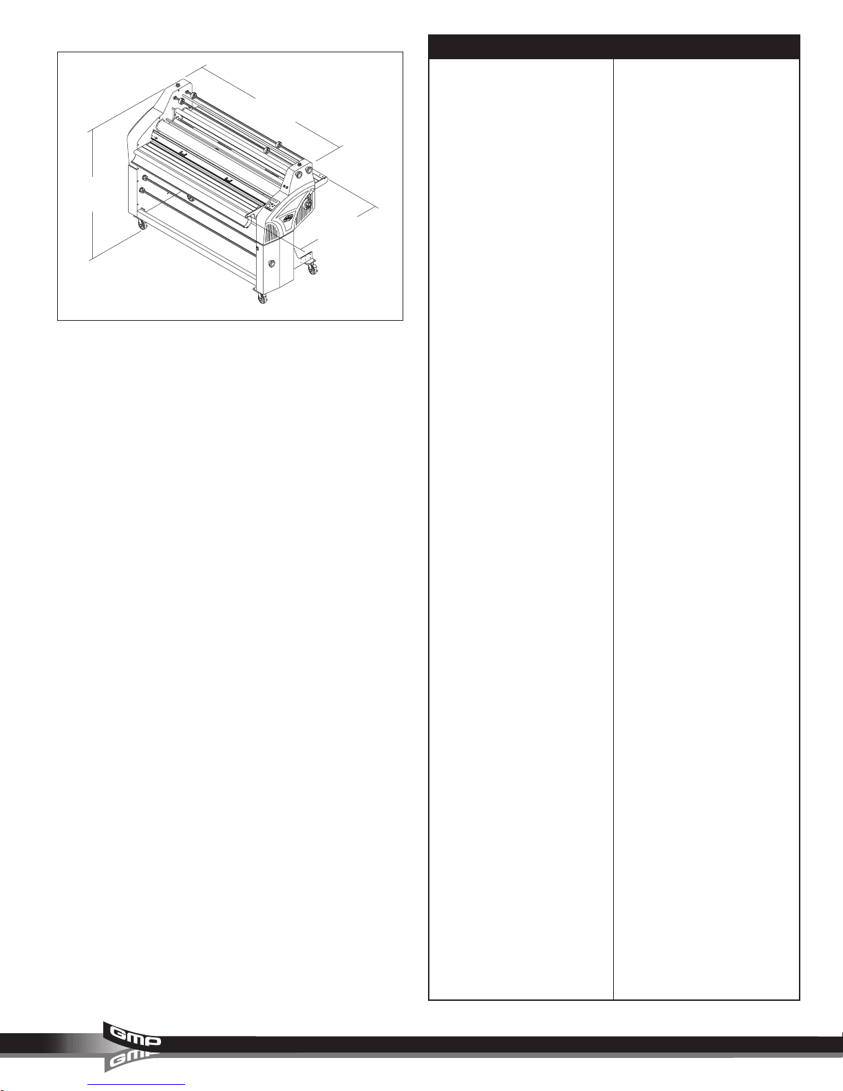
131 cm
211 cm
102 cm
EXCELMASTER-1600
SPECIFICATIONS - EXCELMASTER-1600
Operating Speed:
Up to 5
m/min
Temperature range:
O
C - 150 OC
0
Max. Mounting Thickness:
1.3 cm
Max. Film Width:
EXCELMASTER : 165 cm
Dimensions (W x D x H):
Unit alone: (Figure 2)
211 cm x 102 cm x 131 cm
Shipping:
216 cm x 109 cm x 159 cm
Fig. 1
Weight:
Unit alone:
Shipping:
Electrical Requirements:
Refer to the serial plate located on
the rear of the laminator for the
specific electrical rating applicable
to the unit.
Voltage:
Current:
Power:
Phase:
1030 lb. (467 kg.)
1250 lb. (567 kg.)
400V/50~60 Hz
8.3A
4000 W
Single
4
Page 5
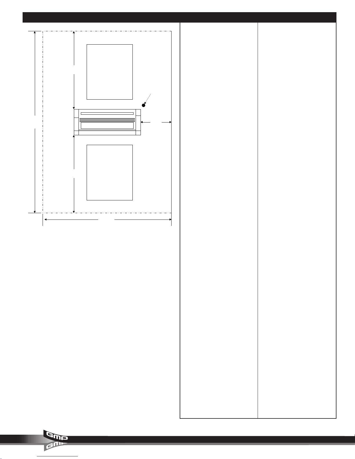
508 cm
220 cm
220 cm
101.6 x 152 cm
Work table on wheels
Back
Front
101.6 x 152 cm
Work table on wheels
Electrical cord
drop
91 cm
PRE-INSTALLATION
Before a Laminator
can be installed, ensure the
following requirements are met;
1. Are door ways and hallways
wide enough for the laminator to
be moved to the installation site?
2. Is there ample room for the
laminator?
– A work area must be
established that allows for
operation in both the front and
rear of the laminator and
provides space for efficient
material flow. (Figure 3)
3. Is the environment appropriate
for the laminator?
– The laminator requires a clean,
dust and vapor free environment
to operate properly.
– Avoid locating the laminator
near sources of heat or cold.
Avoid locating the laminator in
the direct path of forced, heated
or cooled air.
Fig. 2
330 cm
CAUTION: Air flow can cause
uneven heating/ cooling of the
rollers and result in poor
output quality.
4. Have you contacted a certified
electrician to wire the receptacle
and ensure that adequate
power is being supplied, having
the appropriate capacity, over
current protection and safety
lockouts available?
EXCELMASTER requires:
°© 400V at 50/60hz with 15 amp
service. Use a Nema 6-20R.
5
Page 6
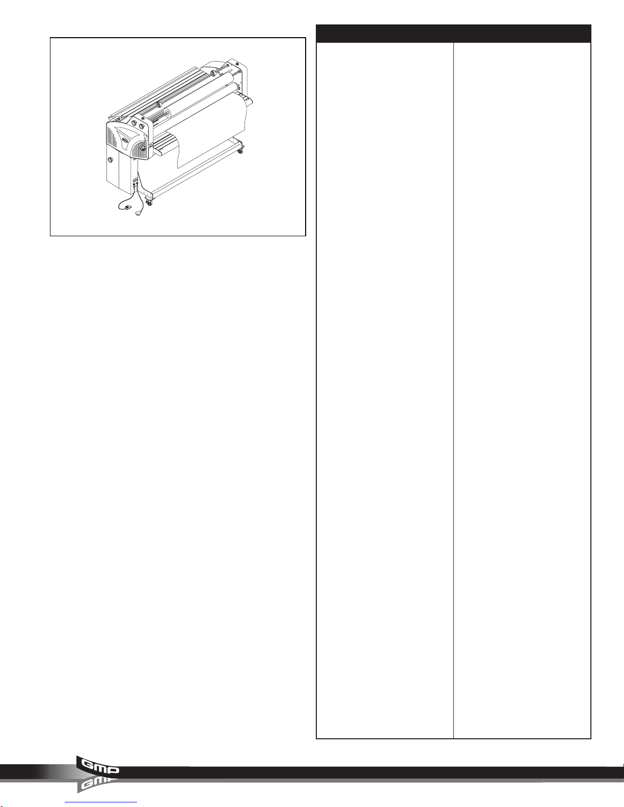
Fig. 3
INSTALLATION
1. Shipping damage should be
brought to the immediate
attention of the delivering
carrier.
2. With assistance, carefully roll
the laminator into position over
flat and even surfaces.
3. The laminator should be
positioned to allow exiting film to
flow freely to the floor or a work
table (Figure 4). Accumulation of
laminate immediately behind the
laminator as it exits the equipment may cause the film to wrap
around the pull rollers, resulting
in a “jammed” condition.
4. Avoid locating the laminator near
sources of heat or cold. Avoid
locating the laminator in the
direct path of forced, heated or
cooled air.
5. Once the laminator has been
properly positioned, lock the
castors in place. Locking the
castors prevent the machine
from rolling during set up,
operation or servicing.
6. Connect the attachment plug
provided with the laminator to a
suitably grounded outlet. Avoid
connecting other equipment
to the same branch circuit to
which the laminator is
connected, as this may
result in nuisance tripping
of circuit breakers or
blowing fuses.
6
Page 7
TOP
BOT0℃
Release
WAIT
Fig. 4
SPEED0℃
JOB
01
03
CONTROL GUIDE
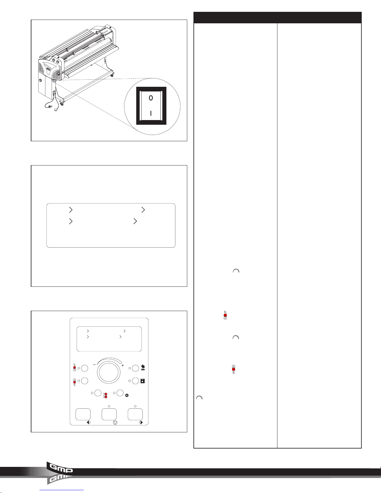
Located at the back left of the
machine applies power to the
laminator. The control panel display
will illuminate when position
marked “l” is pushed. The off
position, marked “O”, removes
power from the laminator.
B. CONTROL PANEL DISPLAY:
(Figure 4) Illuminates when the
laminator is plugged in and POWER
ON/ OFF is in the on, (I), position.
Displays settings for top heater,
bottom heater, speed, Job, mode
and ready/wait/ positioning
indicator.
ROLLER POSITION INDICATOR:
Displays the current main roller
position. In figure 7, the roller is
shown in the “Release” position.
Refer to Roller Handle for more
information.
READY/ WAIT INDICATOR:
“READY” appears when actual
temperature is equal to (+/- 5) set
temperature. “WAIT“ appears
when actual temperature is lower
than the set temperature. “WAIT”
appears when actual temperature
is higher than the set temperature.
POSITIONING INDICATOR:
“Positioning...” appears in place
of the ready/ wait indicator any
time the main rollers are traveling in
an upward or downward motion.
C. CONTROL PANEL: (Figure 6)
MASTER DIAL :
or decreases (-) the numeric value
for the selected setting when
Increases (+)
Fig. 5
display actual temperature of top
and bottom main rollers.
Top Temp. :
When pressed,
permits increasing or decreasing of
TOP
BOT 0℃
Release
WAIT
SPEED0℃
JOB
03
01
the top temperature by turning the
MASTER DIAL
indicated on the control panel
display. Range is 0
and is
O
C
- 150OC).
Top Temp.
Bottom Temp.
Press/Release Coolin g
Speed
Job
Bottom Temp. :
pressed, permits increasing or
decreasing of the bottom temperature by turning the
and is indicated on the control
When
MASTER DIAL
panel display. Range is 32oF 0OC - 150OC.
Rev. Stop Run
Fig. 6
7
Page 8
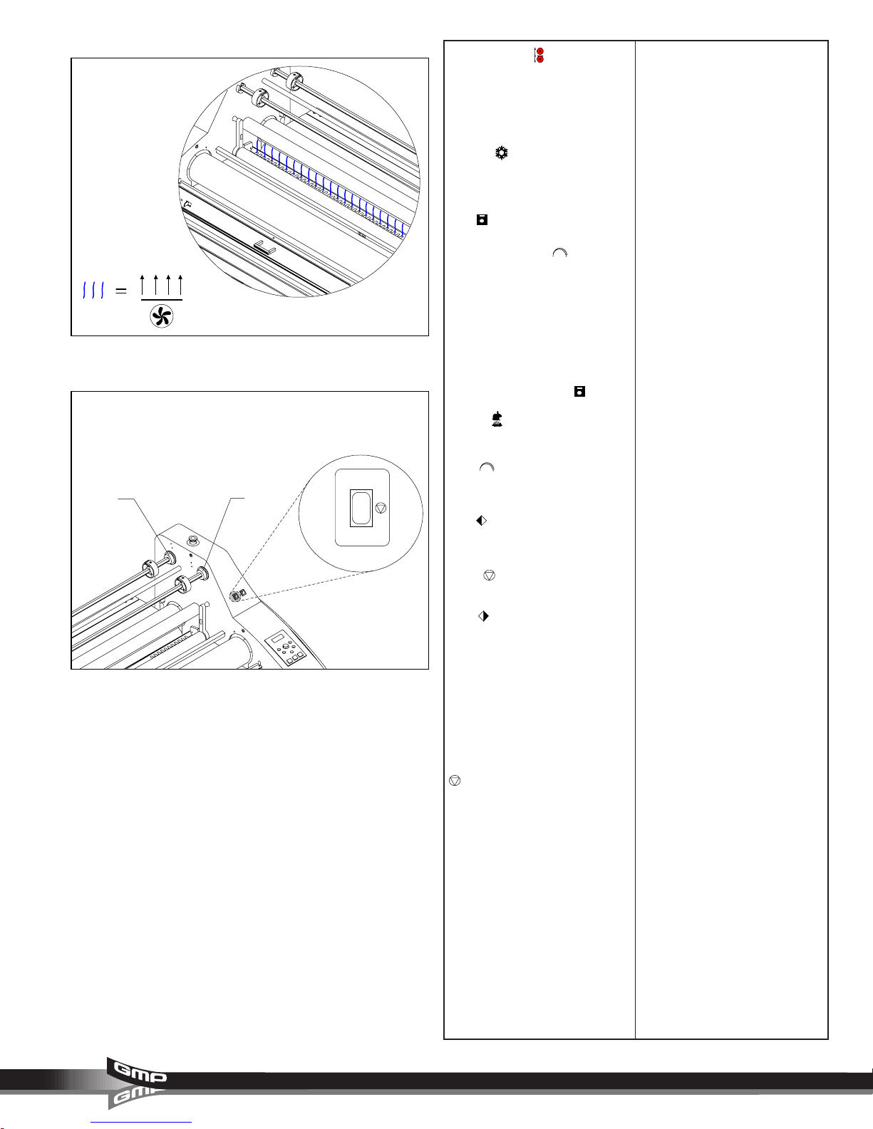
Fig. 7
Press/ Release :
pressed, raises the upper main
roller over riding the pull roller
handle setting. When pressed
again, reverts to current pull roller
handle setting.
Cooling :
pressed, turns on the cooling fans.
When pressed again, turns off the
cooling fans.
JOB :
scrolling of job numbers by turning
the
indicated on the control panel
display. Range is 1 - 10. Job 10 is
reserved for running Accushield
material.
To store parameters for a particular
job number, select the desired job
number location, enter the upper
and lower temperatures and
speed, then press
When pressed, permits
MASTER DIAL
When
(Figure 7) When
and is
JOB
.
Fig. 8
SPEED :
permits increasing or decreasing of
speed by turning the
REWINDER
III
I
II
(D)
DIAL
control panel display. Range is 1 -
10.
REV :
reverses roller movement to clear
film jams and wrap-ups.
STOP :
the rollers.
RUN :
rollers for normal operation.
D. REWINDER SELECTION
SWITCH: (Figure 8) This switch
enables the operator to control the
function of the upper rewind/
unwind shafts.
I : In this position, turns the power
on to the upper front rewind/
unwind shaft.
:
In this position, neither the
upper front or upper rear rewind/
unwind shaft is selected for motor
power.
II : In this position, turns the power
on to the upper rear rewind/
unwind shaft.
When pressed,
MASTER
and is indicated on the
When pressed and held,
Stops the movement of
When pressed, activates
8
Page 9
FWD.
REV.
"REVERSE"
TOP
BOT0℃
Release
Foot SW Enable
FWD.
SPEED0℃
JOB
REV.
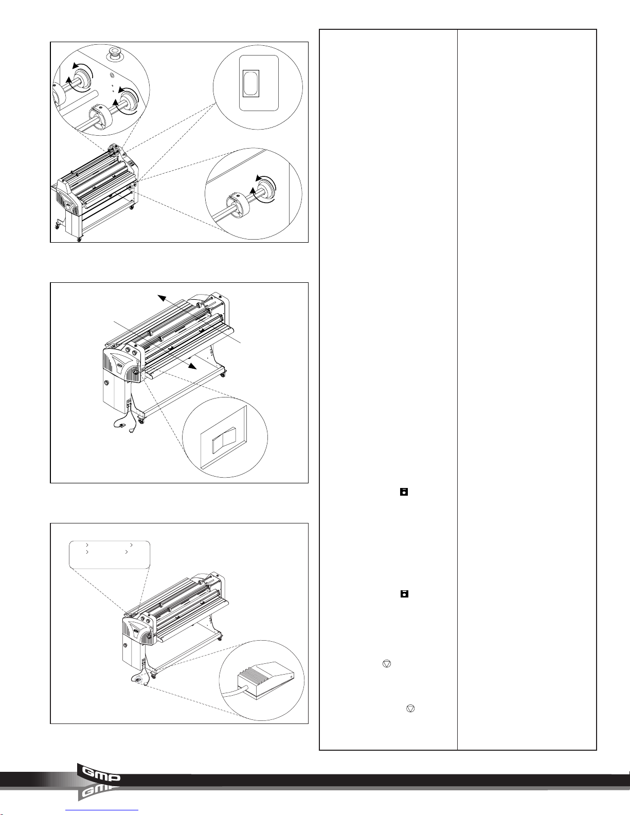
E. UPPER REWINDER DIRECTION
SWITCH: (Figure 9) This switch
REWINDER
FWD.
STOP
REV.
(E) (F)
enables the operator to control the
direction of the upper rewind/
unwind shafts.
“FWD.” : In this position, the motor
runs in a forward direction.
“STOP” : Stops the rewinder motor
for the rewind/ unwind shaft
selected.
“REV.” : In this position, the motor
runs in a reverse direction.
REV.
F . LOWER REWINDER DIRECTION
SWITCH: (Figure 9) This switch
enables the operator to control the
FWD.
direction of the Lower rewind/
unwind shaft.
“FWD.” : In this position, the motor
runs in a forward direction.
Fig. 9
“STOP” : Stops the rewinder motor
for the rewind/ unwind shaft
selected.
“REV.” : In this position, the motor
runs in a reverse direction.
G. REAR CONTROL SWITCH:
(Figure 10) This switch enables the
operator to run jobs from the rear
"RUN"
operating position of the laminator
when rear controls are enabled.
“REVERSE” : In this position, the
rollers turn from the front operating
position towards the rear operating
position.
“STOP” : Stops the movement of
N
U
R
P
O
T
S
E
S
R
E
V
E
R
the rollers.
“RUN” : In this position, the rollers
turn from the rear operating position
(G)
towards the front operating position.
ENABLE REAR CONTROL SWITCH:
To enable the rear control switch,
Fig. 10
press and hold
hear a beep, approximately 3
JOB
until you
seconds. REAR CONTROL
replaces READY/ WAIT on the
control panel display.
03
01
Replace the rear slitter with the
safety shield properly installed and
latched.
DISABLE REAR CONTROL SWITCH:
Press and hold
JOB
again to
disable the rear control switch.
H. FOOT SW ENABLE: (Figure 11)
In this mode permits operation using
the footswitch.
To enable the foot switch, press
and hold
STOP
until you hear a
beep, approximately 3 seconds.
FOOT SW ENABLE flashes where
READY/ WAIT is indicated.
Press and hold
STOP
again to
disable the foot switch.
Fig. 11
9
Page 10
(E)
(1)
(1)
(C)
(A)
(2)
(2)
Fig. 12
Fig. 13
(1)
(B)
(2)
(F)
FEATURES GUIDE
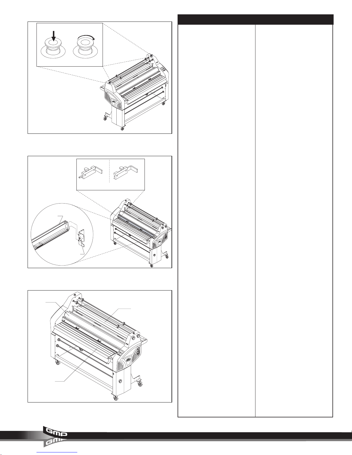
A. E-STOP: (Figure 12) Two E-
STOP buttons exist on the
laminator. One on each side of the
upper cabinet.
To engage (1), press either push
button, roller movement is stopped.
To disengage (2), turn the push
button clockwise once the
emergency condition has been
resolved.
B. SAFETY SHIELD INTERLOCK
LATCH: (Figure 13) Used to lock
the safety shield into position and
activate an interlock switch. The
interlock latch is located on the left
side of the safety shield. When
pushed to the full left (1), the
safety shield is locked. When
pushed to the full right (2), the
safety shield is unlocked.
C. SAFETY SHIELD: (Figure 13)
Prevents entanglement, entrapment
and inadvertent contact with the
heat rollers. The laminator will
operate only when the Safety
Shield is located in the fully
locked position.
To remove the safety shield, unlock
the safety shield interlock latch and
lift the safety shield (1) up and
away from the safety shield
mounting pins (2).
D. FEED TABLE: (Figure 14) The
Feed Table is used to position items
for lamination. The laminator will
operate only when the Feed
Table and Feed Table Latch are
properly installed.
E. HEAT ROLLERS: (Figure 14)
Silicone rubber coated steel tubes
heat the laminating film and
compress the heated film to the
items being laminated. Heat is
provided by an internal heating
element. The heat rollers are motor
driven for ease of loading new film.
F. PULL ROLLERS: (Figure 14) The
pull rollers, located at the back of
the laminator, are motor driven.
They simultaneously pull the film
and improve the quality of the
laminated item.
(D)
Fig. 14
10
Page 11
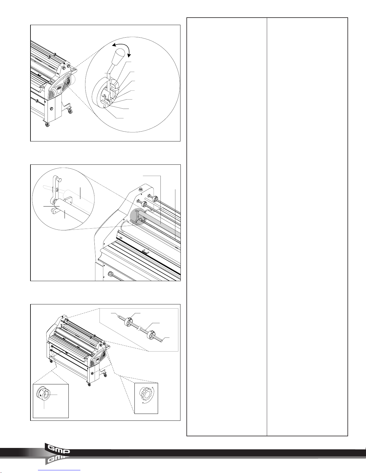
G. ROLLER HANDLE: (Figure 15)
The roller handle manually sets the
position of the pull rollers while
simultaneously electronically setting
the main rollers.
Available settings are;
Release
(G)
15mm Mounting
10mm Mounting
5mm Mounting
3mm Mounting
Low-Prs Laminating
Mid-Prs Laminating
High-Prs Laminating
– Release
– 15mm Mounting
– 10mm Mounting
– 5mm Mounting
– 3mm Mounting
– Low-Prs Laminating
– Mid-Prs Laminating
– High-Prs Laminating
(Prs = pressure)
H. IDLER BAR: (Figure 16) The idler
Fig. 15
bars, located near each heat roller,
are used to direct the film to the
heat roller nip.
I. CHILL IDLER: (Figure 16) Assist
(H)
(2)
in the cooling process of the web
material as it exits the heat rollers.
(J)
To engage the chill idler, grip the
chill idler handles located on each
side of the chill idler and lower to
(I)
the web position (1). To disengage
the chill idler, move the chill idler to
it’s rest position (2).
(1)
J. COOLING FANS: (Figure 16)
Assist in the cooling process by
pushing unheated air onto the web
material as it exits the heated
rollers. This feature can be
controlled from the control panel.
K. FILM SHAFT: (Figure 17) The
film shaft holds the film supply on
the machine.
To remove the film shaft, lift up on
Fig. 16
the round end (1) of the unwind/
rewind shaft then pull the hex end
(2) of the shaft out and away from
the laminator.
(1)
(L)
(K)
L. CORE ADAPTORS: (Figure 17)
Hold and lock the rolls of film on the
shafts to prevent side to side
shifting.
(2)
M. LOWER SHAFT LOCK: (Figure
17) Secures the left side of the
lower shafts. To remove a shaft,
turn the outer dial (1) opening so it
aligns with the inner u-channel (2)
opening and lift up and out.
N. UNWIND/ REWIND TENSION:
(Figure 17) Used to apply resistance to the film shaft.
To increase film shaft tension, turn
the film shaft tension knob
clockwise. Counter clockwise will
decrease film shaft tension.
(1)
(2)
(M)
-
+
(N)
Fig. 17
11
Page 12
(1)
(R)
Fig. 18
(1)
Fig. 19
(Q)
(S)
(2)
(O)
(P)
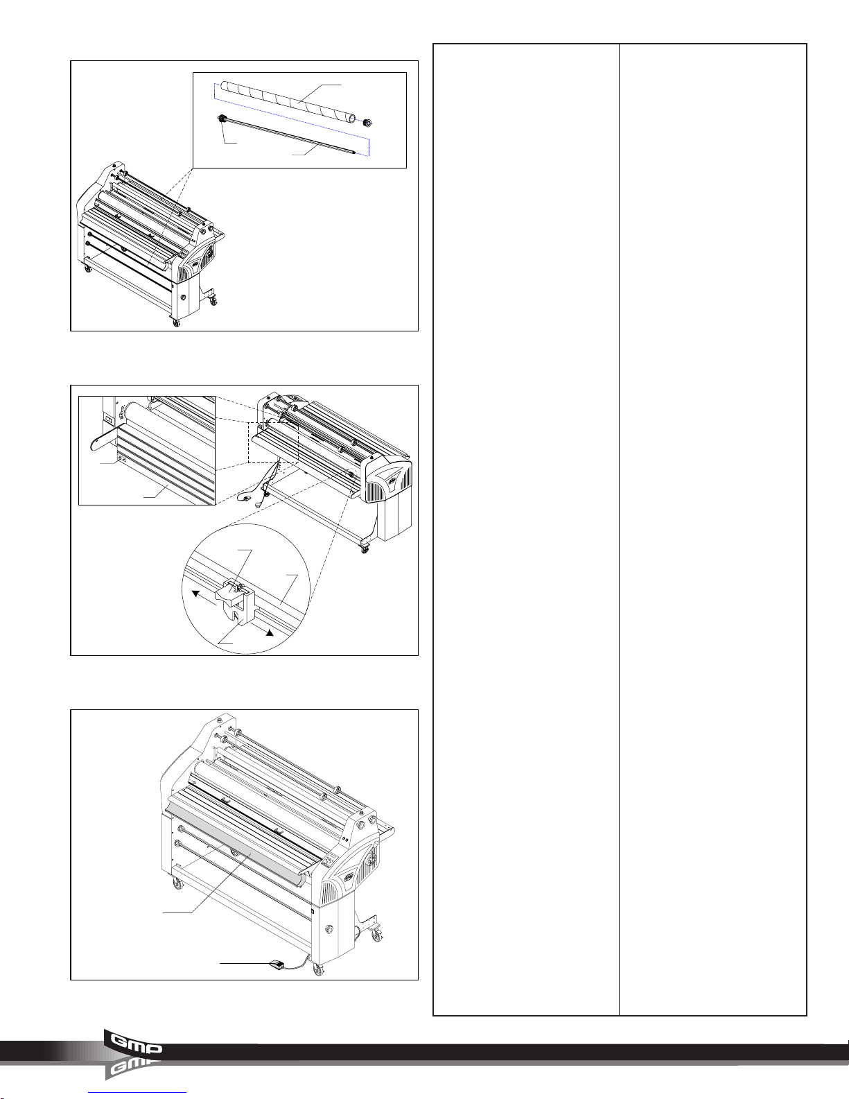
O. REWIND SHAFT: (Figure 18) The
rewind shaft holds the rewind tube
on the machine.
P. REWIND TUBE: (Figure 18) The
two rewind tubes located at the
front of the machine are used to
rewind release liners. The one
located at the rear of the machine
is used to rewind the finished
product.
Q. REWIND ADAPTORS: (Figure
18) Hold and lock the rewind tube
on the rewind shafts to prevent
side to side shifting.
R. REAR TABLE: (Figure 19)
Provides a working surface when
operating the machine from the
rear. This table may also be
lowered when webbing for roll to
roll applications.
To lower, slide the left and right
side rear table latches (1) to the
unlatched position and lower the
rear table.
S. REAR SLITTER: (Figure 19)
Used to cut the film web where it
exits the rear of the laminator.
To make a cut, push down on the
blade engage lever and slide to the
apposite side.
T. FILM WEB: Laminating film
loaded into the machine.
U. NIP POINT: The point at which
the top and bottom rollers come into
contact. The Nip Point of the heat
rollers is the place at which the
items for lamination are introduced
into the laminator.
V. FOOTSWITCH: (Figure 20) Used
to assist in webbing of the machine
and initial feeding of material.
W. PRINT UNWIND BASKET:
(Figure 20) Holds a rolled image.
Prevents the image from touching
the floor.
X. SEPARATOR BAR OPTION:
(Figure 18) Required if running
Micronext® material.
To install, replace the rear slitter
with the separator bar.
Y. REWIND KIT OPTION: Enables
roll to roll webbing of material. This
kit must be installed by a qualified
GMP service representative.
(W)
(V)
Fig. 20
12
Page 13
13
(1)
Polyester surface
Polyester surface
Fig. 21
Fig. 22
Adhesive
surface
Adhesive
surface
Poly-in
Poly-out
OPERATING INSTRUCTIONS
FILM LOADING & THREADING
The top and bottom rolls of
laminating film must be of the same
width and be present simultaneously. A small amount of
adhesive will “squeeze out” during
lamination. Hardened adhesive
deposits can damage the heat
rollers. To avoid any damage,
select “Low-Prs Laminating” on the
roller handle, rotate the rollers at
slowest speed with heat on. Refer
to the section entitled
FOR THE LAMINATOR
for instructions regarding
removal of the accumulated
adhesive.
Adhesive will deposit on the rollers
if:
- Only one roll is used.
- Different widths of rolls are
loaded together.
- Either roll is loaded adhesive
side against a heat roller.
- One or both rolls of film are
allowed to run completely off its
core.
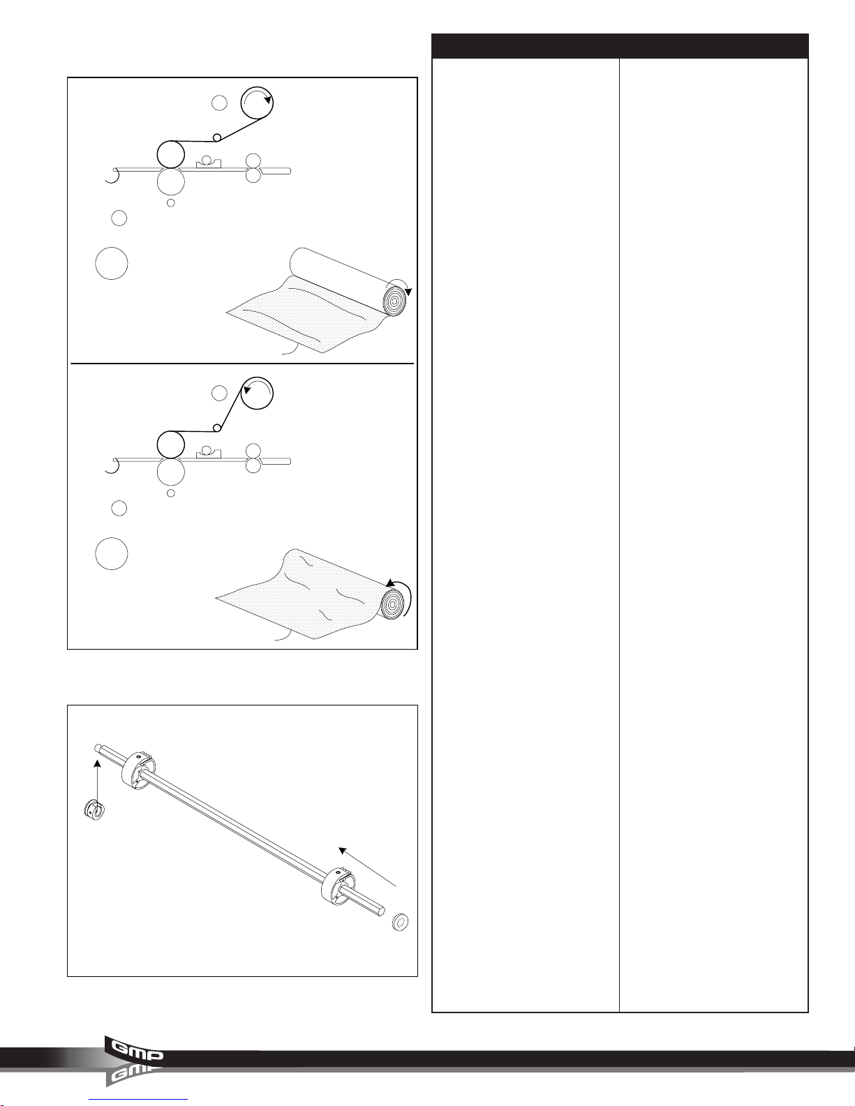
The adhesive side of the film is on
the inner side of the web (Figure
21). The shiny side of clear film
must contact the heat rollers. The
dull side of the film contains the
adhesive. Use extreme caution
when loading delustered (matte)
film as both sides appear dull.
Always change the top and bottom
supply rolls at the same time. Near
the end of each roll of GMP
laminating film is a label stating
“Warning-End of Roll”. The appearance of this label on either the top or
bottom roll requires that new rolls of
film be installed as soon as the item
presently being laminated completely
exits the rear of the laminator. Do not
introduce any additional items into the
laminator when the warning label is
visible.
To load a roll of film; (Figure 22)
1. Lift up on the round end, left
side (1), of the unwind/ rewind
shaft.
2. Pull the hex end, right side (2), of
the shaft out and away from the
laminator.
(2)
3. Slide the roll of film onto the film
shaft ensuring adhesive side is
out.
4. Replace the shaft with the hex
end in first then the round end.
5. Center the roll of film.
CARING
Page 14
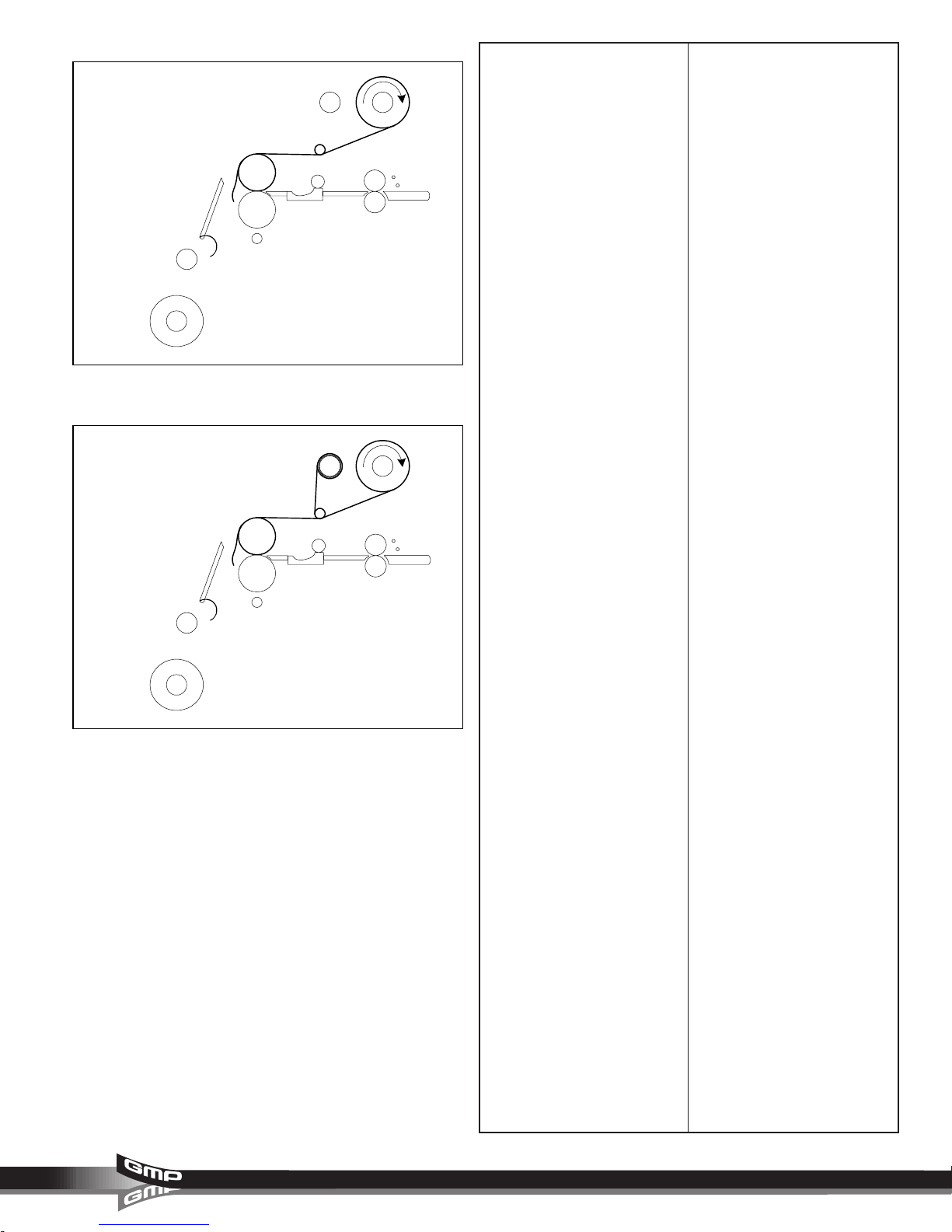
Fig. 23
Fig. 24
LOADING TOP THERMAL FILM
This procedure describes how to
load the upper roll of film onto the
laminator. Figure 23 uses poly-in
film and the upper rear unwind/
rewind position for illustration
purpose.
1. Turn the Power ON/OFF to on
(I). Set top heat temperature for
the film type you are using.
2. Ensure no brake tension is
applied to the film shaft.
3. Remove the safety shield and
pivot the feed table down.
4. Pull the top roll of film down
under the idler bar and allow to
drape over the top heat roller
(Figure 23).
5. Reference one of the loading
bottom material procedures.
LOADING TOP PSA FILM
This procedure describes how to
load the upper roll of film onto the
laminator. Figure 24 uses PSA film
and the upper rear unwind/ rewind
position for illustration purpose.
1. Turn the Power ON/OFF to on
(I). If the laminator is already
hot, turn POWER ON/OFF to the
off (O) position and allow the
unit to cool. Once cool, turn the
laminator back on.
2. Ensure no brake tension is
applied to the film shaft.
3. Remove the safety shield and
pivot the feed table down.
4. Set the roll of film in the rear
unwind/ rewind position and the
rewind tube in the front unwind/
rewind position.
5. Pull the top roll of film down
under the idler bar and up the
upper front rewind tube.
6. Place one piece of masking tape
in the center of the film and
secure to the rewind tube.
7. Make two full wraps around the
rewind tube, then carefully
score the laminate without
cutting the release liner.
8. Pull the laminate down allowing it
to drape over the upper main
roller.
9. Reference one of the loading
bottom material procedures.
14
Page 15
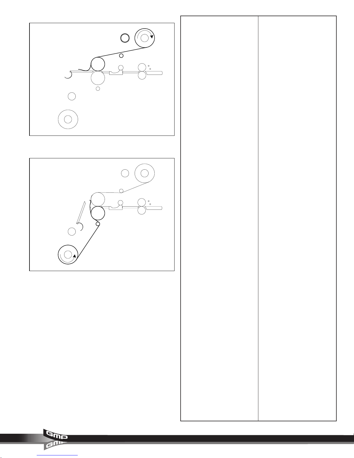
Fig. 25
Fig. 26
LOADING TOP MOUNT ADHESIVE
This procedure describes how to
load a roll of mount adhesive using
the upper position for pre-coating
(Figure 25).
1. Turn the Power ON/OFF to on
(I). If the laminator is already
hot, turn POWER ON/OFF to the
off (O) position and allow the
unit to cool. Once cool, turn the
laminator back on.
2. Ensure no brake tension is
applied to the film shaft.
3. Remove the safety shield.
4. Set the roll of mount adhesive in
the upper rear unwind/ rewind
position.
5. Pull the mount adhesive over the
upper idler and upper main roller
allowing the material to rest on
the top of the feed table.
6. Reference
PROCEDURE
LOADING BOTTOM THERMAL
FILM
This procedure describes how to
load a roll of thermal film using the
lower unwind position for encapsulation (Figure 26).
1. At this point you should have an
upper roll of thermal film loaded
onto the laminator.
2. Ensure no brake tension is
applied to the film shaft.
3. Guide the bottom film around the
lower idler.
3. Adhere the film to the loaded
upper roll of thermal film by
pulling the film up towards the
existing draped thermal film over
the main rollers.
NOTE: You may follow this
procedure to load a roll of Kraft
Paper for single side lamination.
4. Reference
PROCEDURE
THREADING CARD
next.
THREADING CARD
next.
15
Page 16
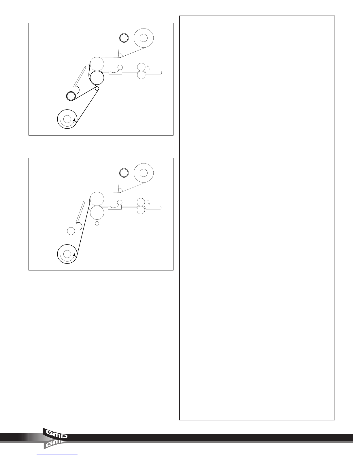
Fig. 27
LOADING BOTTOM PSA FILM
This procedure describes how to
load a roll of mount adhesive using
the lower unwind position for
decaling (Figure 27).
1. At this point you should have an
upper roll of PSA film loaded
onto the laminator.
2. Ensure no brake tension is
applied to the film shaft.
3. Pull the lower roll of film around
the lower idler bar and towards
the lower rewind.
4. Place one piece of masking tape
in the center of the film and
secure to the rewind tube.
5. Make two full wraps around the
rewind tube, then carefully
score the laminate without
cutting the release liner.
6. Adhere the lower PSA film to the
loaded upper roll of film by
pulling the film straight up
towards the main rollers.
7. Reference
PROCEDURE
THREADING CARD
next.
Fig. 28
LOADING BOTTOM MOUNT
ADHESIVE
This procedure describes how to
load a roll of mount adhesive using
the lower unwind position for
decaling (Figure 28).
1. At this point you should have an
upper roll of film loaded onto the
laminator.
2. Ensure no brake tension is
applied to the film shaft.
3. Adhere the mount adhesive to
the loaded upper roll of film by
pulling the mount adhesive
straight up towards the main
rollers. Do not web around the
lower idler.
4. Reference
PROCEDURE
THREADING CARD
next.
16
Page 17
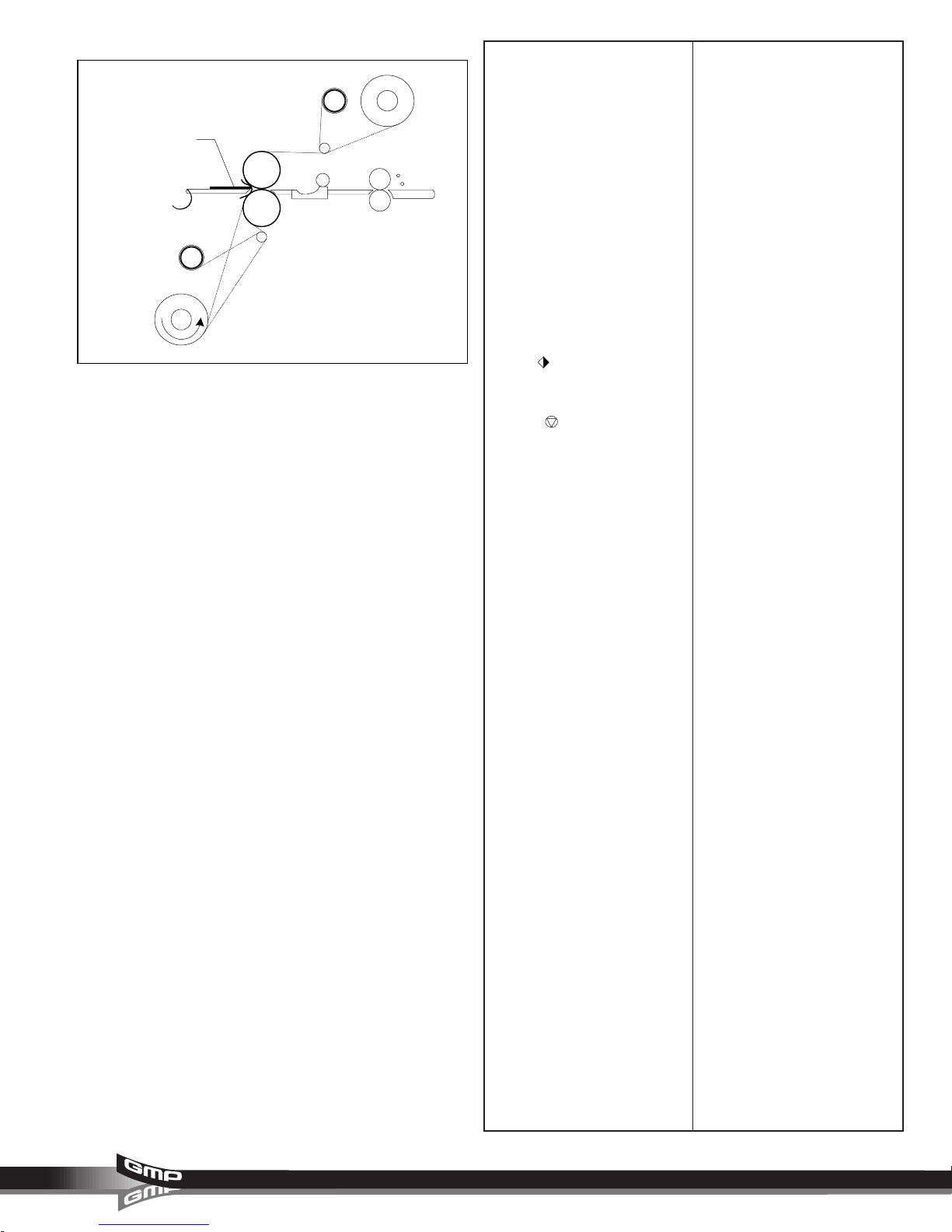
Threading card
Fig. 29
THREADING CARD PROCEDURE
This procedure describes how to
feed two loaded films through the
main rollers (Figure 29).
1. At this point you should have an
upper roll of film and lower roller
roll of film loaded onto the
laminator with the appropriate
material for your application.
2. The table and safety shield must
be properly installed.
3. Push the threading card into the
main roller nip. The threading
card becomes sandwiched
between the upper and lower
loaded films.
4. Set the roller handle to a
laminating position, press the
RUN
5. Once the threading card has
exited the laminator, press the
STOP
6. Use the rear slitter to cut the
threading card from the web.
7. If you are not running the
laminator, set the roller handle to
the “RELEASE” position.
8. Now refer to the section entitled
START LAMINATING
button.
button.
.
17
Page 18
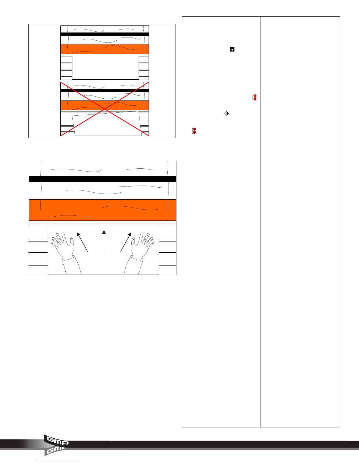
Fig. 30
START LAMINATING
1. The safety shield and feed table
must be in the normal operating
position.
2. Select a job mode (
ensure the proper speed and
temperatures are set. Refer to
the section entitled
) and
SPEED/
TEMPERATURE GUIDE.
3. Set the roller handle to one of
the laminating positions.
4. Press the PRESS/ RELEASE ( )
button. The main rollers gap.
5. Press the RUN ( ) button.
6. Press the PRESS/ RELEASE
( ) button. The main rollers
close.
7. Adjust unwind and rewind
tensions as necessary.
8. Align the leading edge of the
item square to the heat roller nip
(Figure 30).
9. With both hands and an outward
force push the image slower
than the speed of the rollers into
the nip of the heat rollers (Figure
31).
CAUTION: Avoid forcing the
image into the main roller nip
as this action will cause the
corners of the leading edge to
buckle and create a wave.
18
Fig. 31
Page 19
Cut here
Cut here
METHOD FOR TACKING NEW
FILM TO EXISTING FILM
The following describes a method
for loading film whereby the
existing film present on the heat
rollers may be used in place of the
threading card to draw the new
film through the laminator. The
adhesive of the existing film must
be tacky or liquefied. Leading
edges of the new film will be
overlapped onto the tacky adhesive
of the old film. The existing film and
the new film will be pulled through
the laminator together.
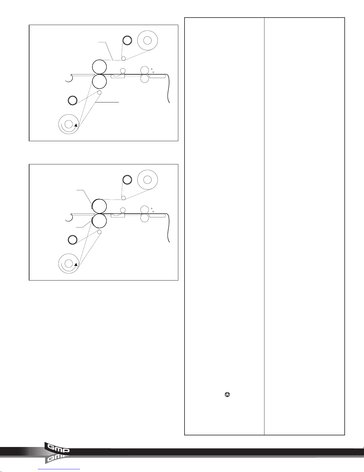
1. Cut remaining top and bottom film
webs between the idler bar and
heat rollers (Figure 32).
New film
New film
Fig. 32
Fig. 33
CAUTION: DO NOT CUT THE HEA T
ROLLERS WHEN CUTTING THE
FILM WEB.
2. Remove the safety shield and tilt
the feed table down.
3. Do not allow the adhesive side
of the film to contact the heat or
pull rollers. Liquefied or tacky
adhesive deposited on heat
rollers will require the rollers to
be cleaned per the section
entitled
CARING FOR THE
LAMINATOR
4. Replace both the top and bottom
rolls of film with new rolls.
Ensure the adhesive side is
facing out.
5. Pull the film around the idler
bars, with the exception of PSA
mounting adhesives without a
release liner.
6. Tack the new film to the existing
film on the heat rollers. For PSA
film, attach the release liner to
the rewind tube (Figure 33).
7. Replace the safety shield and
feed table.
8. Use the footswitch to advance
the film into the heat roller nip.
9. Observe the film being pulled
through the laminator to assure
that the remaining existing film
and the new film are advancing
concurrently. Any separation
between the films will require
stopping the motor immediately
and the situation corrected.
10. Press STOP ( ) once the
newly threaded film has
completely exited the pull rollers.
.
19
Page 20
Pull web
Cut web
Fig. 34
Fig. 35
Cut web
Cut web
TO UNWEB THE LAMINAT OR
Unweb the laminator if you are
changing film widths, cleaning the
rollers or have finished using the
machine for the day.
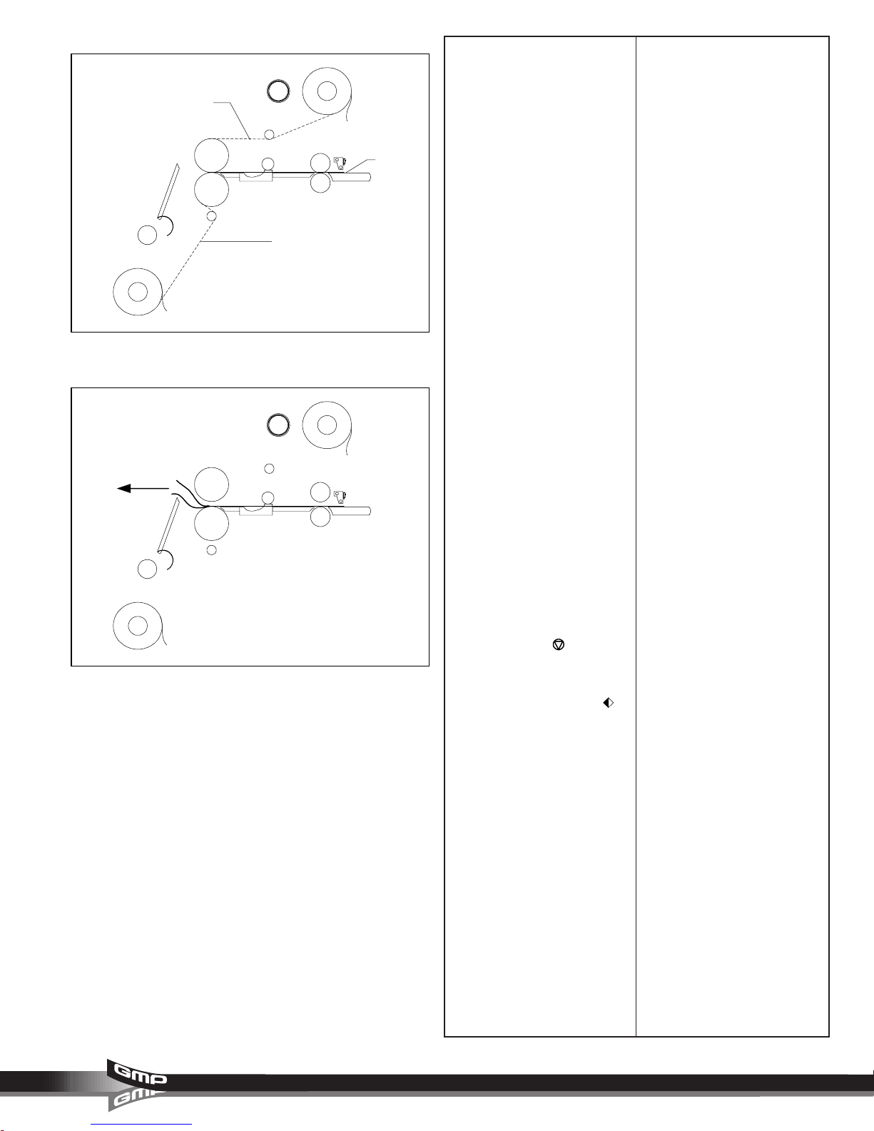
1. Using the rear slitter, cut the
output from the web (Figure 34).
2. Set the roller handle to the
“Release” position.
3. Remove the safety shield and tilt
the feed table.
4. Cut remaining top and bottom film
webs between supply rolls and
heat rollers (Figure 34). Be
careful not to cut any of the
rollers!
5. Carefully grab hold of the web
(top and bottom film), from the
front operating position and pull
towards you (Figure 35).
6. Do not allow the adhesive side
of the film to contact the heat or
pull rollers.
CLEARING A FILM JAM (Wrapup)
Film jams (wrap-ups) may occur if
the film is loaded backwards or if
the area at which film exits the
equipment is blocked. The film,
when jammed, wraps around the
heat rollers during webbing if a
threading card is not used or pull
rollers during operation.
To clear a jam:
1. Immediately stop the laminator by
pressing STOP ( ).
2. Remove the safety shield and tilt
the feed table.
3. Press and hold REVERSE ( )
until the jam has cleared the heat
rollers or pull rollers
4. Set the roller handle to the
“Release” position.
5. Manually assist the material
through the main rollers and/ or
pull rollers.
6. Once the jam has been cleared,
set the roller handle to one of
the laminating positions.
7. You can now resume laminating.
20
Page 21
Trailer board
Board
Fig. 36
Fig. 37
Mount
adhesive
Leader board
APPLICATIONS
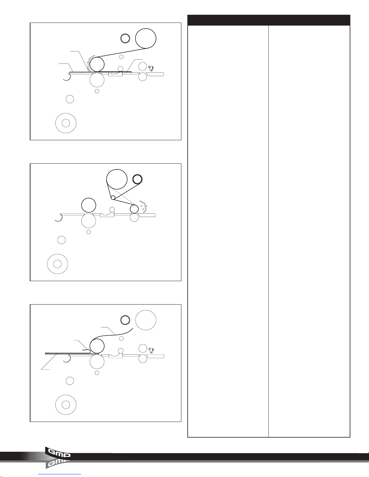
TIPS FOR PRE-COATING BOARDS
(Figure 36)
1. Load the laminator as illustrated
in Figure 36.
2. Ensure the chill idler is in the rest
position.
3. Set the roller pressure handle to
the correct thickness.
4. The width of the roll should not
exceed the width of the board
by more than 1/2 in. (1.3 cm).
5. Use a leader board to start the
run and a trailer board to finish
the run.
6. Using the pull rollers will allow
you to leave gaps between
boards.
7. If not using the pull rollers, have
the boards nearby to butt end to
end during feeding.
TIPS FOR USING THE REAR
ROLLERS (Figure 37)
1. If the front rollers are heated,
you may perform certain
applications from the rear
operating position of the
laminator.
2. Ensure the chill idler is in the rest
position if using boards.
3. Ensure the safety shield is
located in the rear position.
4. Ensure the REAR CONTROLS
have been enabled.
5. You may perform mounting
applications, pre-coating
applications and single side
applications from the rear of the
machine.
Image
Release liner
Pre-coated board
Fig. 38
21
TIPS FOR MOUNTING PRECOATED BOARDS (Figure 38)
1. Load the laminator as illustrated
in Figure 38.
2. Ensure the chill idler is in the rest
position.
3. Ensure the chill idler is removed,
the rear slitter is to one side and
the inline slitters are not
obstructing the path of the
boards.
4. Heat, 125 OF (52 OC), may assist
the process and increase output
quality.
5. Do not stop once you have
started the mounting process
through the machine.
Page 22
Image
Image
Roll
of Kraft
Paper
Roll
of Mount
Adhesive
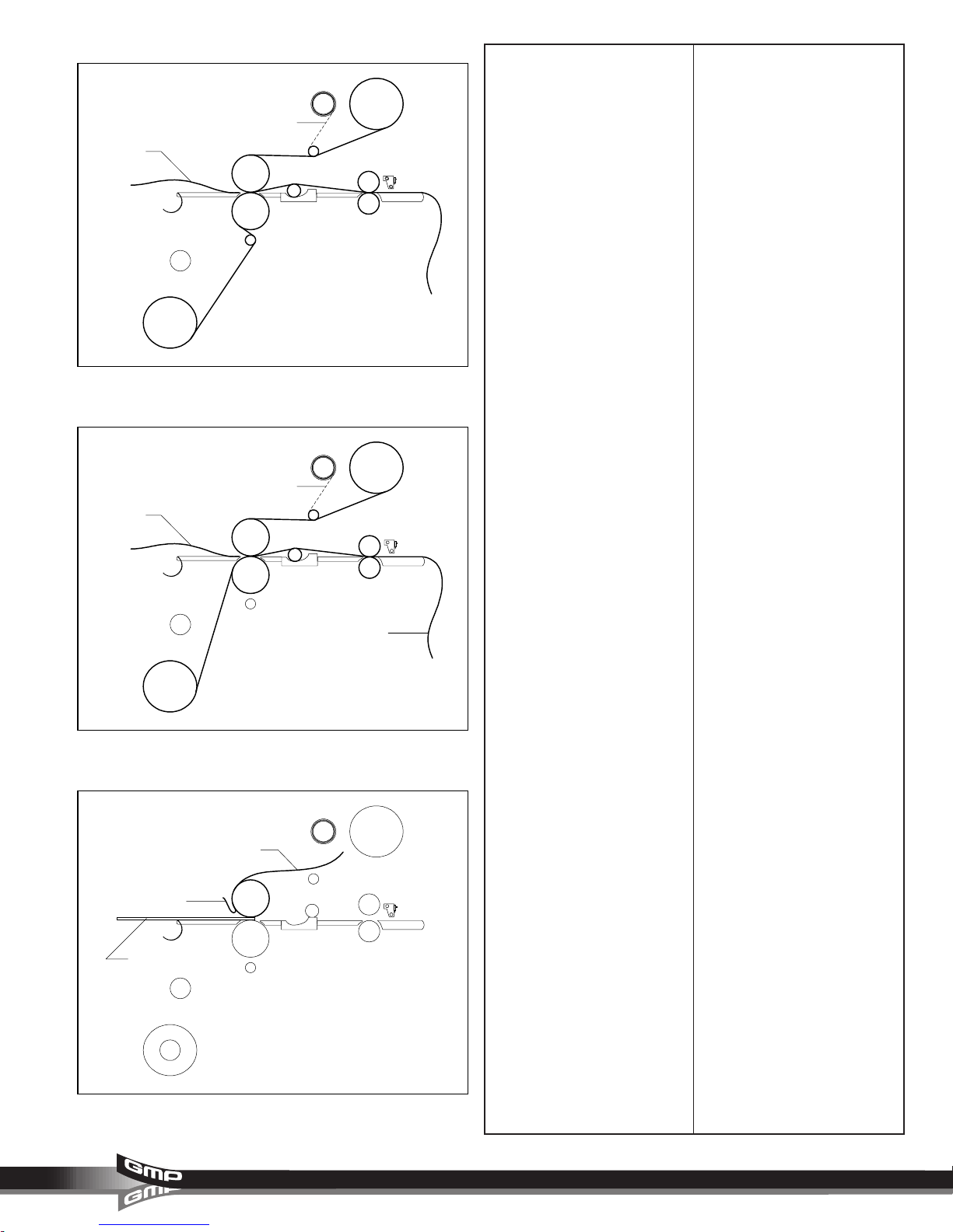
If using PSA Film
Fig. 39
If using PSA Film
of film
of film
Decal
Roll
Roll
TIPS FOR SINGLE SIDED LAMINATION (Figure 39)
1. Load the laminator as illustrated
in Figure 39.
2. Use kraft paper for one-sided
lamination whenever the items to
be laminated are narrower than
the film you are using.
3. If not using kraft paper, use a
scrap piece to finish the run or
you will have adhesive on your
rollers.
4. Running the web over the chill
idler may improve the flatness of
the output.
O
5. A little heat, 125
F (52 OC), may
help eliminate silvering effects
associated with PSA films.
TIPS FOR CREATING A DECAL
(Figure 40)
1. Load the laminator as illustrated
in Figure 40.
2. The over laminate may be PSA
or thermal type.
3. If using thermal type, pay
attention to the Poly-in/ Poly-out
rule.
4. Run a test material prior to
running the actual image to
ensure flat output.
5. Use minimal brake tension to
achieve quality output.
6. Do not web the PSA mount
adhesive around the lower
web idler.
22
Release liner
Board
Fig. 40
Image
Fig. 41
TIPS FOR MOUNTING A DECAL
(Figure 41)
1. Load the laminator as illustrated
in Figure 41.
2. The image should not exceed
the width of the board by more
than 1 in. (2.54 cm) per side.
3. Tack about 1 in. (2.54 cm) of the
leading edge of the decal to the
leading edge of the board.
4. When tacking the leading edge,
start in the center and work to
the sides.
5. Use a board that exceeds the
size of the decal if inexperienced in the mounting application.
Page 23
Image
Image
Roll
of PSA
Film
Poly-in
Fig. 42
Fig. 43
Roll
of PSA
Film
Poly-in
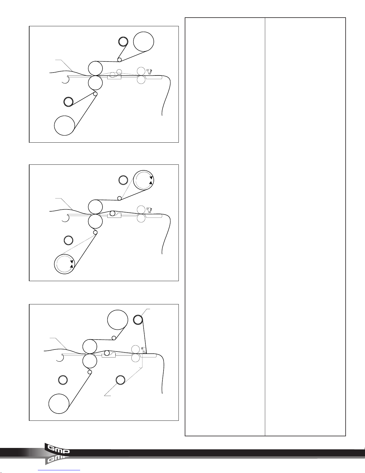
TIPS FOR PSA ENCAPSULATION
(Figure 42)
1. Load the laminator as illustrated
in Figure 42.
2. Always use two rolls of the
same width.
3. Use minimal brake tension to
achieve flat output.
4. The separation of the laminate
and the release liner should be
maintained close to the heat
rollers.
O
5. A little heat, 125
F (52 OC), may
help eliminate silvering effects
associated with PSA films.
6. Use of the chill idler may or may
not help in the output quality. Try
both methods.
TIPS FOR THERMAL ENCAPSULATION (Figure 43)
1. Load the laminator as illustrated
in Figure 43 for Poly-in film.
2. Dotted line represents Poly-out
film web path.
3. Always use two rolls of film the
same width.
4. Use minimal brake tension to
achieve flat output.
5. Increase speed gradually to
maintain the activating temperature required for the laminate
you are using.
6. Length and width of image, ink
coverage and paper type may
effect the temperature and
speed recommended in the
SPEED/ TEMPERATURE GUIDE.
Micronex
Image
Roll of
Kraft Paper
Option
Rewind of Kraft Paper
(Must have roll to roll option)
Fig. 44
23
Rewind of liner
TIPS FOR MICRONEX (Figure
44)
1. Load the laminator as illustrated
in Figure 44.
2. You must have the Separator
bar option to accurately run this
material.
3. Liner rewind tension will be
greater than normal operating
standards.
4. Do not attempt to run this
material greater than a speed
setting of 4.
5. To prevent some adhesive
adhering to the rollers, you may
choose to use a roll of kraft
paper for a carrier with the roll
to roll rewind option installed.
Page 24

THE ART OF LAMINATION
BASIC RULES
Do not attempt to laminate abrasive or
metal objects such as staples, paper clips
and glitter, as they may damage the heat
or pull rollers.
Do not force items into the nip area of the
heat rollers. An item that is not easily
drawn into the laminator by the heat
rollers is probably too thick to laminate.
Wrinkles may result if an attempt is made
to reposition an item once it has been
grasped by the heat rollers.
Do not stop the laminator before an item
has completely exited the pull rollers.
Even a momentary stop will cause a mark
(heat line) on the laminated item.
Good, consistent lamination is a result of
combining proper heat, tension and dwell time.
Dwell time is controlled by the speed of the
motor and is defined as the amount of time the
material to be laminated is compressed between
the heat rollers.
As a general rule, thicker items and film need to
run at slower speeds because they extract
more heat from the rollers at a quicker rate.
Setting the speed control at slower settings
gives the laminator longer dwell time thus
allowing proper lamination of thick items.
Thinner items, such as standard copier paper
(20 lb. bond) and tissue paper, extract less heat
from the rollers and can be run at faster
speeds.
FILM TENSION
Proper film tension, known as brake tension, is
the minimum amount required to eliminate
wrinkles in the finished item. The film should be
taut. A properly adjusted roll of film should not
require excessive force to turn by hand.
Film tension should be enough to introduce a
minor amount of drag as the film unrolls.
Insufficient tension causes wrinkles, while too
much tension causes stretching (necking).
Uneven tension between the top and bottom
rolls create curl. Too much upper tension
creates upward curl while too much bottom
tension causes downward curl.
The pull roller clutch is set at the factory.
Periodic adjustments may be necessary if after
adjusting unwind and rewind brake tensions do
not improve your output quality.
24
Page 25
- A - - B -
Fig. 45
- A - - B -
Fig. 46
HEA T
The “WAIT (Too COLD)” indicator
may appear if the speed is set too
fast for the material being laminated.
Either lower the speed setting or
press STOP
“READY” indicator appears.
Operation of the laminator for more
than thirty minutes at a time may
necessitate a lower speed setting.
It is recommended that, during
periods of long runs, the items
being laminated are alternated
between thick and thin. Do not
combine thick and thin items
at the same time, as this will
result in a poor edge seal
around the thinner material. If
you are unsure that the laminator is
set at the proper speed for the item
to be laminated, run a test piece
(scrap) of the same or similar
material through the laminator. This
procedure is recommended
because rotating the heat roller
prior to lamination will more evenly
distribute the heat. Make speed
adjustments if necessary.
OUTPUT
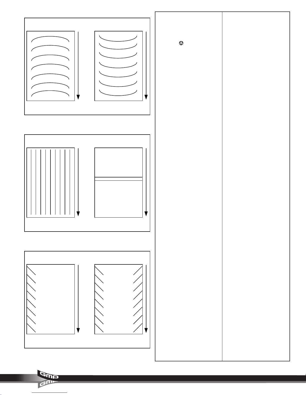
1. “D” waves in the image
(Figure 45 A).
– Check paper tension.
– Paper may be damp or not dry.
2. “D” waves in the laminate
(Figure 45 B).
– Change roller handle pressure.
3. Straight waves in output
(Figure 46 A).
– Check operational settings for
materials being used.
4. Indent waves in output after
pull rollers (Figure 46 B).
– Insufficient cooling time.
– Output was handled prior to
cooling.
– Use cooling feature if not on.
– Machine was stopped on print.
5. Angled waves in the output
(Figure 47 A & B).
– Change roller handle pressure.
– Check for even paper tension
(Figure 46 A only)
and wait until the
- A - - B -
Fig. 47
25
Page 26

MAINTENANCE
CARING FOR THE EXCELMASTER-1600
LAMINATOR
GMP offers Cleaning kits as well as Extended
Maintenance Agreements.
Contact your local GMP Service Representative
or your dealer/distributor for additional information.
The only maintenance required by the operator
is to periodically clean the heat rollers and
schedule semi annual maintenance checks.
The following procedure will help keep the heat
rollers free of adhesive that has been deposited
along the edge of the laminating film. Proper
alignment of the rolls of film reduces the amount
of “squeeze out”.
WARNING: Do not attempt to
laminate adhesives marked
“Flammable”.
• Do not laminate glitter and/ or metallic items.
Damage to the rollers may result.
WARNING: Do not apply any cleaning
fluids or solvents to the rollers.
Some solvents and fluids could ignite on
heated rollers.
• Never clean rollers with sharp or pointed
objects.
• Hardened adhesive deposits on the rollers
can cause damage to the rollers. Rotate the
rollers at the lowest speed setting on the
control panel.
CAUTION: THE FOLLOWING PROCE-
DURE IS PERFORMED WHILE THE
LAMINAT OR IS HOT . USE EXTREME CAUTION.
1. Remove the film from the laminator following
the procedure outlined in steps 1 through 6
of the section entitled
TO UNWEB THE
LAMINATOR.
2. Preheat the laminator until the “READY”
indicator appears.
3. Remove the safety shield and tilt the feed
table.
4. Rub the top and bottom heat rollers with a
3M™ Scotch-Brite™ pad . DO NOT USE
METAL SCOURING P ADS!
5. Use the footswitch to rotate the lower heat/
pull roller to an unclean portion. The upper
heat/ pull rollers are free spinning. Continue
this process until the complete surface of
both rollers are clean.
6. Refer to the beginning of the section entitled
OPERATING INSTRUCTIONS
laminator.
*NOTE: Do not use metal scouring pads to
clean the rollers.
to web your
26
Page 27
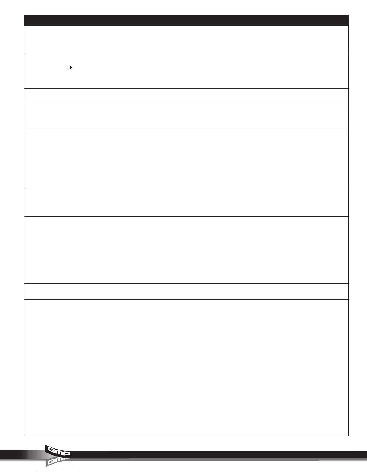
TROUBLESHOOTING GUIDE
SYMPTOM POSSIBLE CAUSE CORRECTIVE ACTION
• The control panel display does not Laminator not connected to Insert attachment plug into receptacle.
illuminate when POWER ON/OFF is electrical supply.
in the ON, marked “I”, position.
• Heat rollers do not turn when I Safety shield is not properly Remove safety shield and properly replace it.
press the RUN ( ) button. installed.
Feed table not properly installed. Tilt feed table and properly replace it.
E-STOP is engaged Pull out on the E-STOP push button.
• Heat rollers only turn if I use Laminator is in Footswitch mode. disengage the footswitch mode.
the footswitch.
• Rear controls do not operate. Rear controls are not enabled. Enable rear controls.
Safety shield is not installed in Remove the rear slitter and install the safety shield.
the rear position.
• Laminated items exhibit curling. Tension between the top and bottom Adjust tension per section
film roll is unequal.
Tension on top or bottom roll of Adjust tension per section
film is too loose.
Speed setting too slow. Slightly speed up the laminator.
Bottom film roll may be improperly Make sure bottom roll of film is around idler bar and the it is in the
loaded. normal operating position.
Chill idler not used. Move the chill idler to the web position.
• Adhesive deposited on heat rollers. Top and bottom film webs not Release heat and pull roller pressure, align the rolls of film.
aligned.
Laminate improperly loaded. Adhesive (matte) side of laminate film may be against the heat
rollers. Unweb and reload the film properly.
• Unsatisfactory adhesion of laminate. Speed setting too fast for type of Lower speed setting by pressing SLOW button to slower speed
material being laminated.
Insufficient heat. Wait for “READY” indicator to appear in the control panel display.
Laminate improperly loaded. Adhesive side of film must be facing away from the heat rollers.
Bottom roll of film not threaded behind the idle bar.
Heat rollers require cleaning. Clean heat rollers per procedure in section
FILM TENSION
FILM TENSION
.
.
Laminated item unsuitable for Item may be dirty or may have nonporous surface that is
adhesion. extremely difficult to laminate.
• Waves in my output See sub section
Nips may be out of calibration. Place a service call for calibration check.
27
OUTPUT
. Under section titled
THE ART OF LAMINATION
.
 Loading...