

Page 1

User Handbook
Gas Measurement Instruments Ltd
Page 2

Issue 8
10/05/17
Part Number: 48160
GMI welcomes comments on all our publications. Your
comments can be of great value in helping us to improve our
customer publications. Please send any comments that you
have to customerservice@gmiuk.com
Copyright © Gas Measurement Instruments Ltd 2008
Page 3

COPYRIGHT
COPYRIGHT
This User Handbook is copyright of Gas Measurement Instruments
Ltd (GMI) and the information contained within, is for use only with
SHIPSURVEYOR instruments. Reproduction, in whole or in part,
including utilisation in machines capable of reproduction or retrieval
without written permission of GMI is prohibited. Reverse engineering
is not permitted.
LIABILITY
Every care has been taken in the preparation of this document, but
GMI do not accept any responsibility for errors or omissions and their
consequences. Information in this document is subject to change
without notice. This document does not constitute a specication or
basis for a contract. Your statutory rights under law are not affected.
MODIFICATION NOTICES
GMI aim to notify customers of relevant changes in the product
operation and maintain this manual up to date. In view of the policy
of continuous product improvement there may be operational
differences between the latest product and this manual.
This Handbook is an important part of the SHIPSURVEYOR product.
Please note the following points:
• It should be kept with the instrument for the life of the product.
• Amendments should be attached.
• This Handbook should be passed on to any subsequent
owner / user of the instrument.
• Although every care is taken in the preparation of this
Handbook, it does not constitute a specification for the
instrument.
SOFTWARE
Software supplied on EPROM or similar device for use in a particular
product, may only be used in that product and may not be copied
without the written permission of GMI. Reproduction or disassembly
of such embodied programmes or algorithms is prohibited. Ownership
of such software is not transferable and GMI does not warrant that
the operation of the software will be error free or that the software
will meet the customer’s requirements.
i
Page 4

USER HANDBOOK
DISPOSAL ADVICE
When no longer in use, dispose of the instrument carefully and with
respect for the environment. GMI will dispose of the instrument
without charge if returned to the factory.
SAFETY
• The instrument must be regularly serviced and calibrated by
fully trained personnel in a safe area.
• Batteries: Alkaline or *Rechargeable batteries must be
exchanged (*and recharged) in a safe area and fitted
correctly before use.
Never use damaged batteries or expose to extreme heat.
See Chapter 5 : OPERATOR MAINTENANCE.
• Only GMI replacement parts should be used.
• If the instrument detects gas, follow your own organisation’s
procedures and operational guidelines.
• Shipsurveyor instruments are certied as
ATEX II 2 G Exd ia IIB T3 Gb (-20oC < Tamb < 50oC).
IEC Ex d ia IIB T3 (-20oC < Ta < +50oC)
• This equipment conforms to standard EN 50104.
• This equipment is also designed and manufactured to comply
with MED Directive 0038/YY (Module B&E). Further detail
of the Marine Equipment Directive, is located on the MED
declaration of conformity, supplied with the instrument.
Any right of claim relating to product liability or consequential
damage to any third party against GMI is removed if the warnings
are not observed.
WARNING: To prevent ignition of flammable or combustible
atmospheres, remove batteries before servicing.
WARNING: To prevent ignition of flammable or combustible
atmospheres, read, understand and adhere to the manufacturer’s
live maintenance procedures.
WARNING: To reduce the risk of ignition of a flammable or
explosive atmosphere, batteries must be changed only in a
location known to be non-hazardous.
ii
Page 5

COPYRIGHT
WARNING: To reduce the risk of explosion, do not mix old
batteries with used batteries or mix batteries from different
manufacturers.
WARNING: Never attempt to recharge non rechargeable cells.
CAUTION: Not for use in oxygen enriched atmospheres.
CAUTION: Replace instrument batteries only with approved
batteries, as follows:
ATEX APPROVED INSTRUMENTS:
Alkaline (LR20 ‘D’ size): Duracell Procell; Duracell
Industrial; Duracell Plus; Energizer Ultra; Energizer
Industrial.
Rechargeable (LR20 ‘D’ size): Uniross 2600mAh NiMH.
AREAS OF USE
Do not use instrument in potentially hazardous atmospheres
containing greater than 21% Oxygen. The enclosure material
is polypropylene and must not be exposed to environments
which are liable to result in mechanical or thermal degradation
or to damage caused by contact with aggressive substances.
Additional protection may be required in environments where the
instrument enclosure is liable to damage.
STORAGE, HANDLING AND TRANSIT
Rechargeable batteries contain considerable energy and care
should be taken in their handling and disposal. Batteries should be
removed if the instrument is stored for longer than 3 months. The
instrument is designed to handle harsh environments and is IP54
rated. If not subjected to misuse or malicious damage, the instrument
will provide many years of reliable service. The instrument contains
electrochemical sensors with a life of 2 years. Under conditions of
prolonged storage the sensors should be removed. The sensor
contains potentially corrosive liquid and care should be taken when
handling or disposing of the sensor, particularly when a leak is
suspected.
WARRANTY
The SHIPSURVEYOR instrument has a warranty against faulty goods
or workmanship of 2 years. Consumable and Mechanical parts are
not included in this. These are covered under GMI standard warranty
conditions. For details, please contact GMI Ltd (UK).
iii
Page 6

USER HANDBOOK
iv
Page 7

CONTENTS
COPYRIGHT ..................................................................i
LIABILITY .......................................................................i
MODIFICATION NOTICES .............................................i
SOFTWARE ...................................................................i
DISPOSAL ADVICE ...................................................... ii
SAFETY ......................................................................... ii
AREAS OF USE ........................................................... iii
STORAGE, HANDLING AND TRANSIT ....................... iii
WARRANTY ................................................................. iii
INTRODUCTION ................................................ 1-1
GENERAL INFORMATION .................................. 2-1
2.1 Instrument Models / Ranges ................................ 2-1
2.2 Details of Operating Ranges................................ 2-2
2.2.1 LEL, 0 - 100 % ............................................... 2-2
2.2.2 Volume Gas, 0 - 100 % (CGI mode only) ....... 2-3
2.2.3 Oxygen (O2), 0 - 25 % .................................... 2-3
2.2.4 Hydrogen Sulphide (H2S), 0 - 100 ppm .......... 2-4
2.2.5 Carbon Dioxide (CO2), 0 - 20 % ..................... 2-4
2.2.6 Carbon Monoxide (CO), 0 - 1000 ppm ........... 2-5
v
Page 8

USER HANDBOOK
2.3 Operating Modes ................................................. 2-6
Conned Space Monitor (CSM) Operation ............. 2-6
Combustible Gas Indicator (CGI) Operation ........... 2-6
2.4 Alarms .................................................................. 2-7
2.5 Datalogging.......................................................... 2-7
2.5.1 Location (LOC) Selector ................................. 2-8
2.6 Max / Min Values ................................................. 2-8
2.7 Construction......................................................... 2-8
2.8 Batteries............................................................... 2-8
2.9 Filters ................................................................... 2-9
2.10 Liquid Crystal Display (LCD).............................. 2-9
2.11 Before Use Checks .......................................... 2-10
OPERATION ........................................................ 3-1
3.1 Instrument Features............................................. 3-1
3.2 Operating Buttons ................................................ 3-2
3.3 Probe Handle / Quick Connect ............................ 3-3
3.4 Operating Modes - Switch ON ............................. 3-3
3.5 Language Option ................................................. 3-4
3.6 Instrument Identication ...................................... 3-5
3.7 Time / Date .......................................................... 3-6
3.8 Calibration Due Date ........................................... 3-6
3.9 Service Due Date............................................... 3-12
vi
Page 9

CONTENTS
3.10 Sensor Zeroing ................................................ 3-18
3.10.1 Instrument Will Not Zero - Zero Fault ......... 3-18
3.10.2 Instrument Will Not Zero - Gas Present ..... 3-20
3.11 Alarm Warning (CGI mode only) ...................... 3-21
3.12 Warm-up Complete .......................................... 3-22
3.13 Alarms (CSM mode only) ................................. 3-22
3.14 LEL / Vol Gas Range Selection (CGI mode only) ....
................................................................................. 3-23
3.15 Switch Pump OFF / ON (CGI mode only) ........ 3-23
3.16 Zero All Ranges (CGI mode only) .................... 3-23
3.17 Datalogging...................................................... 3-24
3.17.1 CSM Mode ................................................. 3-24
3.17.2 CGI Mode ................................................... 3-25
3.18 Max / Min Values ............................................. 3-25
3.19 Location (LOC) Selector .................................. 3-28
3.19.1 To select a location (LOC): ........................ 3-28
3.20 Acknowledge Alarms (CSM mode only)........... 3-30
3.21 Switch the instrument OFF .............................. 3-31
3.22 Button Operation Summary ............................. 3-32
ALARMS .............................................................. 4-1
4.1 Gas Alarms .......................................................... 4-1
4.1.1 FLAMMABLE (LEL) ALARMS ....................... 4-2
4.1.2 OXYGEN (O2) ALARMS ................................ 4-2
4.1.3 TOXIC ALARMS (e.g. CO) ........................... 4-3
vii
Page 10

USER HANDBOOK
4.2 Alarm Types ......................................................... 4-4
4.2.1 LATCHING / NON-LATCHING ...................... 4-4
4.2.2 MUTING / ACKNOWLEDGING ..................... 4-4
4.3 Default Alarm Settings ......................................... 4-4
4.3.1 Default Alarms Table ...................................... 4-5
4.4 Alarm Examples ................................................... 4-6
4.4.1 EXAMPLE 1 (LEL HiHi ALARM)................... 4-6
4.4.2 EXAMPLE 2 (O2 LoLo ALARM) .................... 4-7
4.4.3 EXAMPLE 3 (CO STEL ALARM) ................. 4-8
4.5 Fault Alarms ......................................................... 4-9
4.5.1 Fault Alarms - CSM Mode ............................ 4-10
4.5.2 Fault Alarms - CGI Mode ...............................4-11
4.5.3 ZERO FAULT .............................................. 4-12
4.5.4 SENSOR FAULT ......................................... 4-13
4.5.5 FLOW FAULT .............................................. 4-14
4.5.6 MEMORY FAULT (Calibration / Conguration) ...
.............................................................................. 4-15
4.5.7 MEMORY FAULT (General Instrument) ...... 4-16
4.5.8 LOW BATTERY ........................................... 4-16
4.5.9 BATTERY EXHAUSTED ............................. 4-17
OPERATOR MAINTENANCE ............................. 5-1
5.1 Batteries............................................................... 5-1
5.1.1 Replace Alkaline / Rechargeable Cells .......... 5-2
viii
Page 11

CONTENTS
5.2 Filter Replacement............................................... 5-5
5.2.1 Internal Filter .................................................. 5-5
5.2.2 Probe Handle (Accessory) - Part No. 48120 .. 5-5
CALIBRATION .................................................... 6-1
6.1 Calibration Validity ............................................... 6-2
ACCESSORIES................................................... 7-1
ADDITIONAL INFORMATION ............................ 8-1
8.1 Training ................................................................ 8-1
8.2 World Wide Web .................................................. 8-1
TYPICAL OPERATING PARAMETERS ..............A-1
Dimensions ............................................................. A-2
Weight ..................................................................... A-2
Operating Temperature ........................................... A-2
Humidity .................................................................. A-2
Construction ............................................................ A-2
Display .................................................................... A-2
Warm-Up / Stabilization Time .................................. A-2
Typical Flow Rate Information .................................A-2
Response Time (T90) ..............................................A-2
Power Source .......................................................... A-2
ix
Page 12

USER HANDBOOK
QUICK OPERATING INSTRUCTIONS ...............B-1
CHECKLIST ...............................................................B-2
SAFETY ..................................................................... B-2
AREAS OF USE ........................................................ B-3
OPERATION ..............................................................B-4
Switch ON ............................................................... B-4
Range Selection (CGI only) .................................... B-5
Switch Pump OFF / ON (CGI only) ......................... B-5
Zero All Ranges (CGI only) in Fresh Air .................. B-5
Manual Datalogging ................................................ B-5
Max / Min Values .....................................................B-5
Enter (LOC) Location List ....................................... B-6
Acknowledge Alarms (CSM only) ............................B-6
Switch OFF ............................................................. B-6
INDEX...................................................................... I
x
Page 13
1
INTRODUCTION
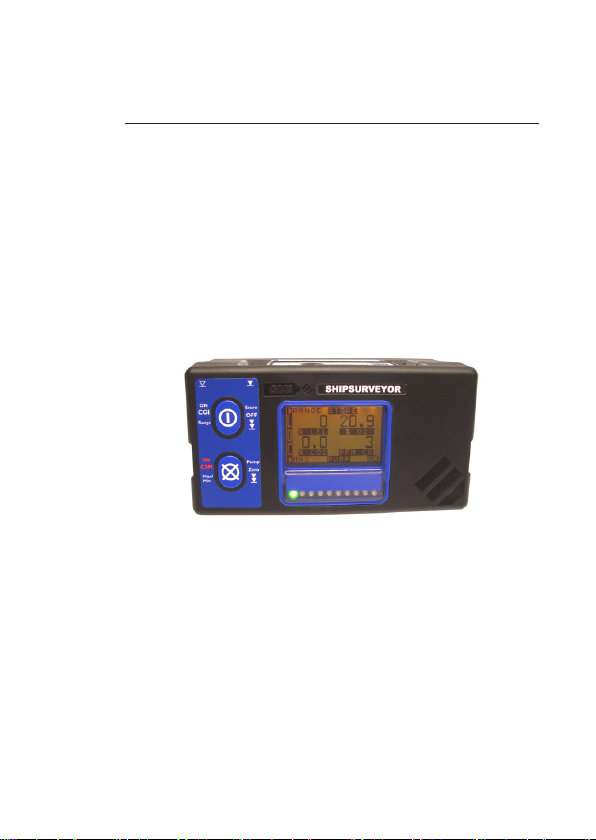
The GMI - SHIPSURVEYOR instrument is a single
instrument solution for all your safety monitoring and inerting
applications.
This extremely versatile instrument complies with international
marine regulations for Conned Space Monitoring, Inerting,
Pre-entry Testing, Tank Cleaning and many other marine
applications.
Fig. 1-1 Shipsurveyor Instrument
As a minimum, the instrument provides measurement of
Lower Explosive Level (LEL) and Volume ammable gas
for Shipping Industry surveying and leak detection. Other
gas ranges are available, as detailed in Chapter 2 of this
handbook.
The SHIPSURVEYOR has a variety of user congurable
options. This handbook details the default conguration,
with possible options detailed in italic text.
1-1
Page 14

USER HANDBOOK
The instrument is supplied in a sturdy carrying case that is
able to accommodate a selection of accessories.
For a comprehensive list of accessories that are supplied in
the carrying case and additional accessories available, refer
to Chapter 7 ‘ ACCESSORIES’.
The main features of the SHIPSURVEYOR are:
• A gas detection instrument that is simple to
operate with easy maintenance procedures.
• Two button operation allowing the user access to all
features.
• Two operating modes: Confined Space Monitor
(CSM) mode and Combustible Gas Indicator (CGI)
mode.
• LCD with backlighting which displays the current
gas readings together with operational and status
information.
• Clear battery life indication.
• Audible and Visual alarms enabled in CSM mode
only. Alarm levels are pre-set and an optional
periodic confidence signal is emitted. The
audible and visual condence signals will provide
assurance that the instrument is sensing for gas
without the need for the operator to constantly
view the display. The signals, which consist of
an audible ‘beep’ and a visual pulse of the LED
approximately every eight seconds, are active in
CSM mode.
• Manual and automatic datalogging is available in
CSM mode.
Manual datalogging is available in CGI mode.
1-2
Page 15
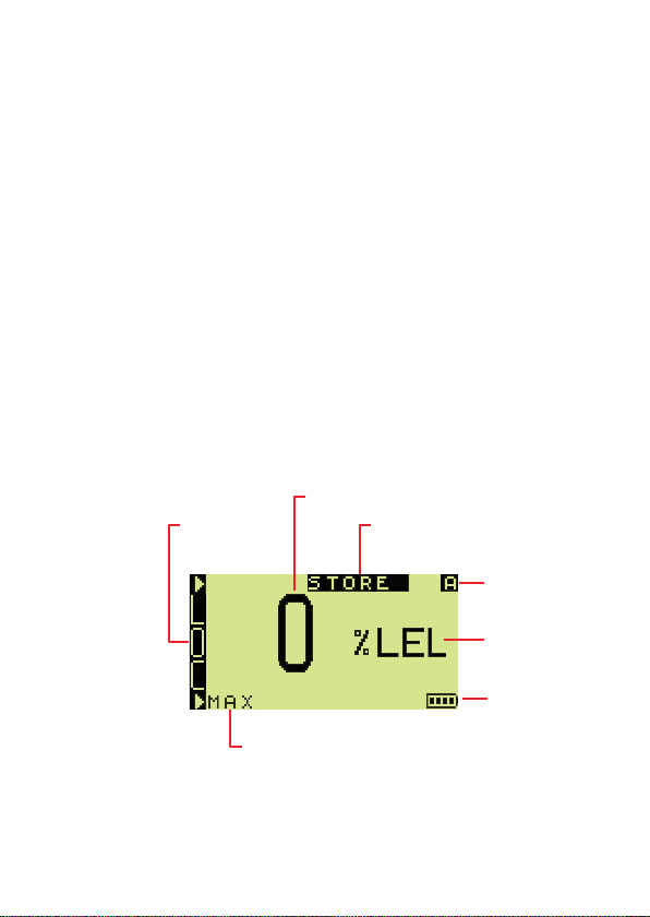
Manual
Datalogging
Live Reading
View Max Values
(or Min if option displayed)
Location
Selector
Alarms
Activated
Gas
Range
Battery
Status
INTRODUCTION
• Rugged polypropylene case, sealed to IP54 rating
and suitable for outdoor use.
• Directly interfaces with GMI Auto Calibration Unit.
During normal operation, the top and / or bottom line of the
instrument display indicates button press options.
If the option is not highlighted, a single press of the adjacent
button selects that option.
If the option is highlighted, a press and hold of the adjacent
button selects that option.
An audible ‘beep’ will be heard for a single button press,
and two ‘beeps’ will be heard for a press and hold, of either
buttons.
Fig. 1-2 illustrates a typical CSM mode LEL display for a
Shipsurveyor 1.
Note: A congurable option allows the instrument to display
this range type as LFL (Lower Flammable Limit).
Fig. 1-2 CSM Button Press Options
1-3
Page 16
USER HANDBOOK
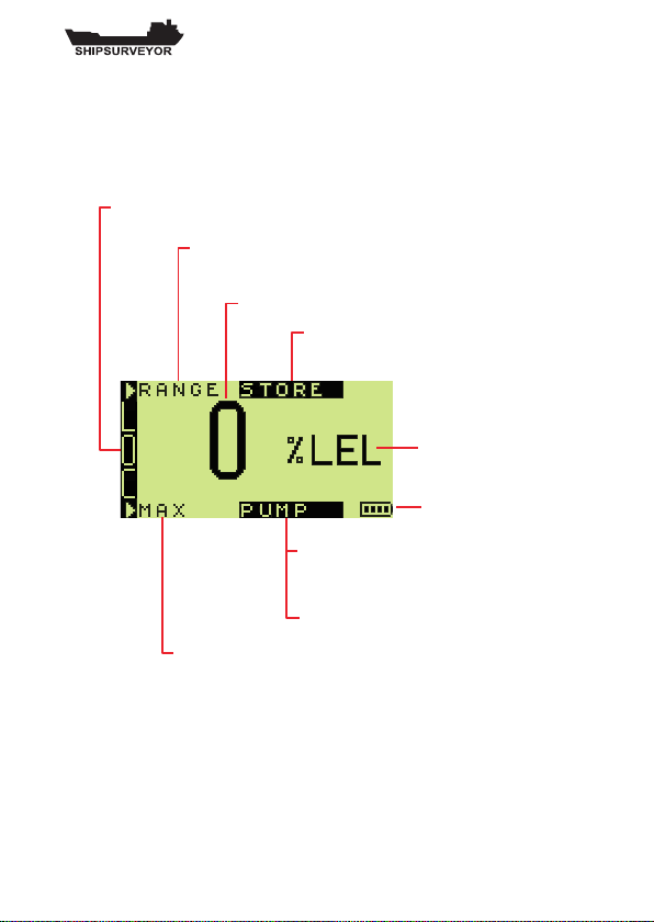
Manual
Datalogging
Toggle Pump
OFF / ON
Zero All Ranges
Live Reading
Location Selector
View Max Values
(or Min if option displayed)
Toggle Flammable Range
(LEL to VOL)
Gas
Range
or
Battery
Status
Fig. 1-3 illustrates a typical CGI mode LEL display for a
Shipsurveyor 1.
Note: A congurable option allows the instrument to display
this range type as LFL (Lower Flammable Limit).
Fig. 1-3 CGI Button Press Options
Note: Figs. 1-2 and 1-3 illustrate instrument displays
with datalogging enabled (including LOC panel
and STORE option). If instrument LOC selector is
disabled, the display does not show the LOC panel.
1-4
Page 17
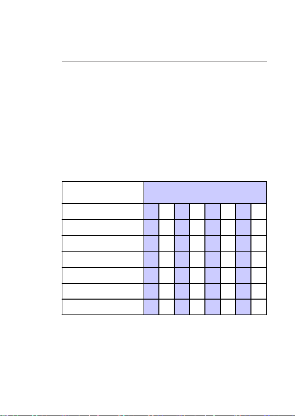
SENSORS FITTED
(* IR = infrared)
SHIPSURVEYOR MODELS
1 2 3 4 5 6 7 8
0-100% LEL (IR)
X X X X X X X
0-100% VOL GAS (IR)
X X X X X X X
0-25% Oxygen
X X X
X X X X
0-100ppm Hydrogen Sulphide
X X X
0-20% Carbon Dioxide (IR)
X X X X
0-1000ppm Carbon Monoxide
X X
2
GENERAL INFORMATION
2.1 Instrument Models / Ranges
There are eight (8) models in the SHIPSURVEYOR range of
instruments. Not all detection ranges may be included in the
version of instrument selected by your company.
The table below illustrates each model and corresponding
gas sensor ranges included:
Fig. 2-1 Gas Ranges / Instrument Model
2-1
Page 18

USER HANDBOOK
2.2 Details of Operating Ranges
The basic instrument can measure 0-100% LEL and
0-100% VOL GAS.
Other models can measure the following gas types:
• Oxygen (O2)
• Hydrogen Sulphide (H2S)
• Carbon Dioxide (CO2)
• Carbon Monoxide (CO)
2.2.1 LEL, 0 - 100 %
The LEL range indicates the explosivity of the ammable
gas in the sample. This is displayed as a percentage of the
lower explosive limit (LEL) of the gas.
% LEL is displayed clearly in the LCD. From 0 - 100% LEL,
the digital display resolves to 1% LEL.
A congurable option allows the displayed LEL value to
have a resolution of 0.1% LEL from 0 - 9.9%, and 1% LEL
from 10 - 100%.
When the reading reaches 100% LEL, EEE (over-range) is
displayed. The user can, by using the top button, change
range to % Volume Gas in CGI mode only.
An example of a 10% LEL gas detection reading is illustrated
in Fig. 2-2 (example from Shipsurveyor 1 model).
2-2
Fig. 2-2 LEL Example (CGI mode)
Page 19
GENERAL INFORMATION
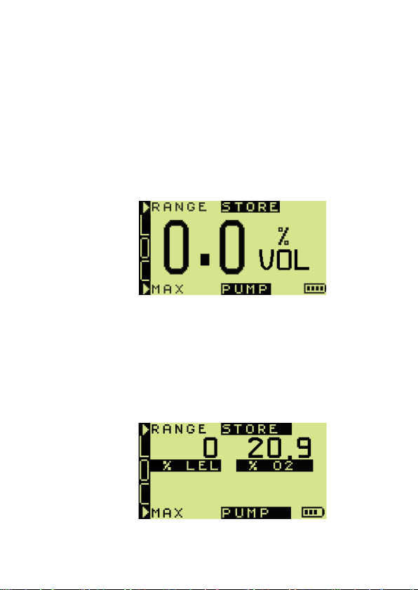
2.2.2 Volume Gas, 0 - 100 % (CGI mode only)
This range displays the total volume of a ammable gas.
% VOL is displayed clearly in the LCD. The displayed VOL
gas value has a resolution of 0.1% VOL from 0 - 9.9%, and
1% VOL from 10 - 100%.
A congurable option allows the displayed VOL gas value
to have a resolution of 1% VOL from 0 - 100%.
Fig. 2-3 illustrates a typical VOL Gas display (example from
Shipsurveyor 1 model).
Fig. 2-3 Volume Gas Example
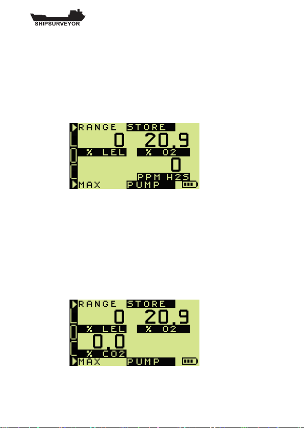
2.2.3 Oxygen (O2), 0 - 25 %
This range displays the % of oxygen in the sample.
% O2 is clearly displayed in the LCD. The displayed oxygen
value has a resolution of 0.1% O2 from 0 - 20.9%, and 1%
from 21 - 25%. Fig. 2-4 illustrates a typical display including
Oxygen (example from Shipsurveyor 2 model).
Fig. 2-4 Oxygen Example
2-3
Page 20
USER HANDBOOK
2.2.4 Hydrogen Sulphide (H2S), 0 - 100 ppm
This range displays the parts per million (ppm) of Hydrogen
Sulphide in the sample.
H2S is clearly displayed in the LCD. The displayed
hydrogen sulphide value has a resolution of 1 ppm.
Fig. 2-5 illustrates a typical display including Hydrogen
Sulphide (example from Shipsurveyor 3 model).
Fig. 2-5 Hydrogen Sulphide Example
2.2.5 Carbon Dioxide (CO2), 0 - 20 %
This range displays the percentage of Carbon Dioxide in
the sample.
CO2 is clearly displayed in the LCD. The displayed carbon
dioxide value has a resolution of 0.1% CO2 from 0 - 5%,
and 0.5% from 5 - 20%. Fig. 2-6 illustrates a typical display
including Carbon Dioxide (example from Shipsurveyor 4
model).
2-4
Fig. 2-6 Carbon Dioxide Example
Page 21
GENERAL INFORMATION
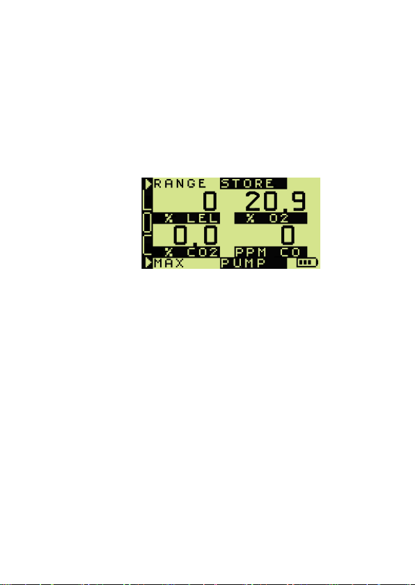
2.2.6 Carbon Monoxide (CO), 0 - 1000 ppm
This range displays the parts per million (ppm) of Carbon
Monoxide in the sample.
CO is clearly displayed in the LCD. The displayed carbon
monoxide value has a resolution of 1 ppm. Fig. 2-7 illustrates
a typical display including Carbon Monoxide (example from
Shipsurveyor 5 model).
Fig. 2-7 Carbon Monoxide Example
2-5
Page 22

USER HANDBOOK
2.3 Operating Modes
Conned Space Monitor (CSM) Operation
In this mode the instrument operates as a safety monitor
for use when entering confined spaces which may
contain hazardous gas mixtures (ammable, toxic and/or
asphyxiant). The instrument continually samples the ambient
atmosphere to which the operator is exposed and generates
alarms for low oxygen, high oxygen, high ammable gas,
high toxic gas, Short Term TWA (STEL) and Long Term
TWA (LTEL).
During normal operation in CSM mode, the instrument
emits a condence beep and illuminates a pair of red LED’s
briey every 8 seconds. This function is programmable in
the instrument setup software.
The condence signal function makes the user aware that
the instrument is sensing for gas without the need for the
operator to constantly view the display:
The condence beep and / or LED indication can be disabled.
Combustible Gas Indicator (CGI) Operation
In this mode the instrument operates as a gas indicator
drawing a sample via a probe from points where gas is
suspected to be present. Alarms are disabled in CGI mode
as the instrument is generally used for measuring gas levels
rather than monitoring for the presence of gas.
2-6
Page 23

GENERAL INFORMATION
2.4 Alarms
The SHIPSURVEYOR alarms are disabled in Combustible
Gas Indicator (CGI) mode. When operating in Conned
Space Monitor (CSM) mode, both audible and visual alarms
are active, (refer to Conned Space Monitor Operation in
Chapter 3). The audible alarm is rated at 85 dB(A). The
visual alarm consists of two (2) pairs of red LED’s ashing
alternately in the display panel.
The instrument, by default, will have alarm levels pre-set,
(refer to ‘Default Alarms’ table in Chapter 4).
It is the responsibility of the user to ensure that the alarm
levels, where set in the instrument, are appropriate for
the safe operation and legal requirements for the country
/ industry in which the unit is being used.
Latching alarms can only be cleared manually after the
detected gas level has fallen below the alarm limit.
An option allows the alarms to be non-latching. These clear
automatically when the gas levels fall below the alarm limit.
Another option allows the audible alarm to be muted.
TWA alarms, by default, are non-latching.
2.5 Datalogging
The SHIPSURVEYOR memory can store over 1000 logged
entries in date order. The memory will overwrite entries in
the event of an overow.
The instrument, by default, has automatic and manual
datalogging enabled when operating in CSM mode. Manual
datalogging allows the user to store a snapshot of the gas
readings at any time.
When the instrument is operating in CGI mode, only manual
datalogging is enabled. There is no automatic datalogging
available in this mode.
2-7
Page 24

USER HANDBOOK
Alkaline Rechargeable
Two (2) Cells
> 20 hrs > 8 hrs
2.5.1 Location (LOC) Selector
The SHIPSURVEYOR instrument features a ‘LOC’ location
selector, allowing the user to allocate datalogged readings
to a location (LOC) of a vessel. Refer to Chapter 3.18 for
more details.
2.6 Max / Min Values
The SHIPSURVEYOR instrument records the maximum /
minimum gas values for each sensor, since switch-on.
2.7 Construction
The instrument is housed in a tough, impact resistant,
moulded case made of polypropylene.
The top panel features a carbon loaded polycarbonate
LCD cover.
The battery cover is attached to the main instrument body
by means of two stainless steel hexagonal screws.
The instrument is sealed against dust and water to IP54
standard. The instrument sensors are protected from dust
and water by an integral hydrophobic lter.
2.8 Batteries
The SHIPSURVEYOR instrument can operate on either two
(2) alkaline or rechargeable cells. Typical operating times
are as follows:
Fig. 2-8 Typical Battery Operating Times
A battery symbol, as illustrated in Fig. 2-9, provides an
indication of remaining battery life. The symbol is displayed in
2-8
Page 25

GENERAL INFORMATION
100%
75%
50%
25%
the bottom RH corner of the display during normal operation.
Fig. 2-9 Remaining Battery Life
Refer to Chapters 4.5.7 and 4.5.8 for detailed battery
warnings.
To replace batteries, refer to Chapter 5, ‘OPERATOR
MAINTENANCE’.
2.9 Filters
Note: The SHIPSURVEYOR instrument has an integral
hydrophobic lter tted.
To remove / install integral hydrophobic filter, refer to
‘MAINTENANCE MANUAL’ (GMI Part No. 48166).
Where possible an external lter (accessory) should always
be used to prevent ingress of dust / water.
2.10 Liquid Crystal Display (LCD)
The dot matrix LCD (128 x 64) shows the current gas
readings in a clear, digital form. Operational and status
information is also displayed. Backlighting is controlled by an
optical sensor that illuminates automatically during warm-up,
when an alarm is active, and also in low lighting conditions.
2-9
Page 26

USER HANDBOOK
2.11 Before Use Checks
The following checks should be carried out before every
operation:
• The instrument is clean and in good condition.
• The sample line and any accessories are in
good condition and leak free. Make sure that the
instrument displays a flow fault when the
instrument inlet / sample line is blocked. If a
ow fault is not displayed, check tightness of all
ttings.
• Any accessory lters used are clean and in good
condition.
• The batteries have sufficient power left for the
intended use of the instrument.
• The instrument is still within the calibration period
and is calibrated for the gas that you are intending
to sample.
• All gas ranges are operational and zeroed
correctly.
2-10
Page 27
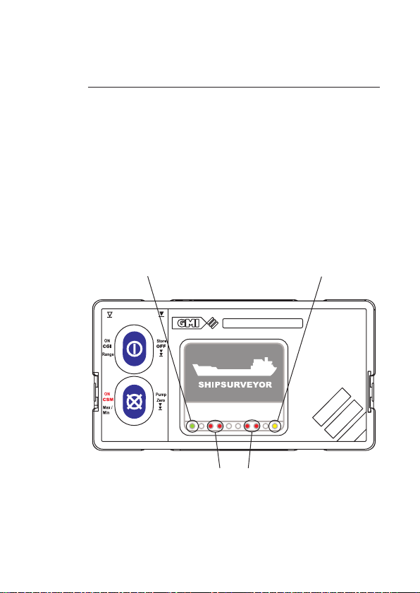
SHIPSURVEYOR
ALARM CONDITION (4 RED) LED's
and CONFIDENCE SIGNAL in CSM mode (outer 2 RED LED's)
POWER ON
(GREEN) LED
FAULT LED
(YELLOW)
3
OPERATION
3.1 Instrument Features
The SHIPSURVEYOR front panel features two operating
buttons, a Liquid Crystal Display (LCD) illuminated in low
lighting conditions, and a series of status LED’s as illustrated
in Fig. 3-1,
Fig. 3-1 Instrument Front Panel
3-1
Page 28
USER HANDBOOK
The POWER ON LED is green in colour and indicates that
the instrument is powered ON.
The ALARM LED’s are red in colour and, when ashing,
indicate that the instrument is in an alarm condition.
Refer to Chapter 4 ‘ALARMS’ for details.
The CONFIDENCE SIGNAL LED’s (CSM mode only) are
also red in colour and provide assurance that the instrument
is sensing for gas without the need for the operator to
constantly view the display.
The FAULT LED is yellow in colour and when illuminated,
indicates that a fault has been detected. Refer to Chapter
4.2 ‘Fault Alarms’, for details.
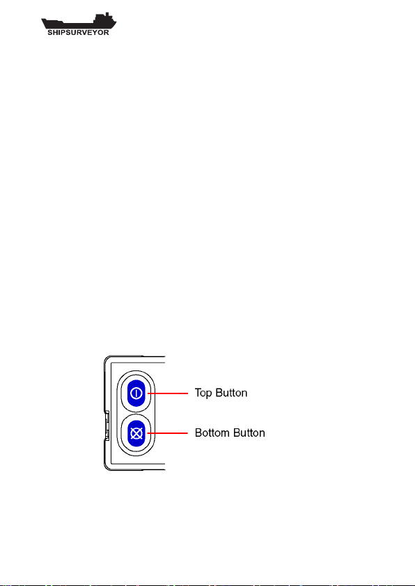
3.2 Operating Buttons
The SHIPSURVEYOR features two operating buttons, as
illustrated in Figure 3-2.
All functions are easily accessible by a single press or a
press and hold of the relevant button.
Each button press is acknowledged with a ‘beep’ sound.
Each press and hold is acknowledged by two ‘beeps’.
Fig. 3-2 Switch Panel
Refer also to paragraph 3.21 ‘Button Operation Summary’
later in this chapter.
3-2
Page 29
OPERATION
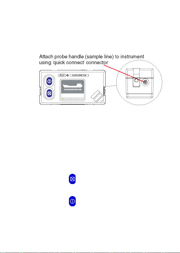
3.3 Probe Handle / Quick Connect
The SHIPSURVEYOR instrument is equipped to accept
probe types listed in Chapter 7 ‘Accessories’.
Fig. 3-3 Probe Connection
3.4 Operating Modes - Switch ON
The SHIPSURVEYOR is a dual conguration instrument.
It operates as a Conned Space Monitor (CSM) or as a
Combustible Gas Indicator (CGI) depending on the button
used to switch it on.
For Confined Space Monitor (CSM) operation, the
instrument must be switched on by pressing and holding the
Bottom Button for approximately one second in fresh air.
For Combustible Gas Indicator (CGI) operation, the
instrument must be switched on by pressing and holding
the Top Button for approximately one second in fresh air.
3-3
Page 30

USER HANDBOOK
The title screen is displayed, as illustrated in Fig. 3-4, the
pump is activated and the instrument begins its warm-up
routine that lasts approximately 60 seconds. During the
warm-up cycle, a countdown timer appears in the top right
hand corner of the display.
The display backlight illuminates and remains ON during
warm-up.
Fig. 3-4 Title Screen
3.5 Language Option
The language setup has three congurable options:
• English (Default)
• Other (single) language
• Choice of language
During the warm-up cycle, the language screen, as illustrated
in Fig. 3-5, is only displayed if ‘choice of language’ is
congured. This allows the user to select a pre-programmed
language from the menu. The previously selected language
is highlighted in the display.
3-4
Fig. 3-5 Language Selection
Page 31

OPERATION
Note: If choice of language is not congured, the warm-
up cycle will automatically continue with the
congured language.
To select the required language option
• Single press the Top Button , or single press
Bottom Button , to highlight required language.
• Press and hold OK (the Bottom Button) to
conrm selection.
3.6 Instrument Identication
During the warm-up cycle, the instrument display identies
the model, serial number, software version, datalogging,
battery status and calibration gas information as illustrated
in Fig. 3-6:
Fig. 3-6 Instrument Identication
Note: The battery symbol is indicated during the warm up cycle, then on the bottom RH corner of the
display during normal operation.
3-5
Page 32

USER HANDBOOK
3.7 Time / Date
The current time and date is displayed during the warm-up
cycle, as illustrated in Fig. 3-7.
Fig. 3-7 Time and Date
3.8 Calibration Due Date
The CAL DUE period can be set from 1 to 400 days and is
set to 365 days by default.
The CAL DUE date is automatically reset when the
instrument is successfully calibrated.
The CAL DUE feature has ve (5) congurable options:
1. CAL DUE DATE MESSAGE IS NOT DISPLAYED
(OPTION)
2. CAL DUE DATE MESSAGE IS DISPLAYED
(OPTION)
Cal Due date message is displayed, as illustrated in
Fig. 3-8.
3-6
Page 33

OPERATION
Fig. 3-8 Calibration Due Date
If the Cal Due date has expired, i.e. overdue, the
screen illustrated in Fig. 3-9 is displayed.
Fig. 3-9 Calibration Expired
After approximately ve (5) seconds, the
instrument warm-up continues.
3. CAL DUE DATE MESSAGE IS DISPLAYED WITH
USER ACKNOWLEDGE IF EXPIRED (DEFAULT)
Cal Due date message is displayed, as illustrated
in Fig. 3-10.
3-7
Page 34

USER HANDBOOK
Fig. 3-10 Calibration Due Date
If the Cal Due date has expired, i.e. overdue, the
screen illustrated in Fig. 3-11 is displayed.
Fig. 3-11 Calibration Overdue
The user must acknowledge that Cal Due date has
expired.
To accept expiry (continue):
• Press YES (Top Button) to continue
the warm-up cycle.
To acknowledge expiry:
• Press NO (Bottom Button) to abort.
The screen, illustrated in Fig. 3-12 is
displayed.
3-8
Page 35

OPERATION
Fig. 3-12 Switch OFF
• Press and hold the Top Button to
switch the instrument OFF.
4. CAL DUE DATE MESSAGE IS DISPLAYED
- USER ACKNOWLEDGE FOR EXTENDED
PERIOD IF EXPIRED (OPTION)
Cal Due date message is displayed, as illustrated in
Fig. 3-13.
Fig. 3-13 Calibration Due Date
If the Cal Due date has expired, i.e. overdue, but
within the ‘extended period’, the screen illustrated in
Fig. 3-14 is displayed.
3-9
Page 36

USER HANDBOOK
Fig. 3-14 Calibration Overdue
The user must acknowledge that Cal Due date has
expired.
Note: The extended period can be set from 1 to 31
days.
To accept extended expiry (continue):
•
Press YES (Top Button) to continue
the warm-up cycle.
Note: When the extended period option expires, the
user will be forced to switch the instrument
OFF.
To reject the extended expiry:
• Press NO (Bottom Button) .
The screen, illustrated in Fig. 3-15, is displayed.
3-10
Fig. 3.15 Calibration Expired
Page 37

OPERATION
To proceed with the shut-down sequence:
• Press and hold the Top Button to
switch the instrument OFF.
5. CAL DUE DATE MESSAGE IS DISPLAYED USER SHUT-DOWN IF EXPIRED (OPTION)
Cal Due date message is displayed as illustrated in
Fig. 3-16.
Fig. 3-16 Calibration Due Date
If Cal Due date has expired, the screen illustrated in
Fig. 3-17 is displayed.
Fig. 3.17 Calibration Expired
To proceed with the shut-down sequence:
• Press and hold the Top Button to
switch the instrument OFF.
3-11
Page 38

USER HANDBOOK
3.9 Service Due Date
The Service due date can be set by the workshop and is set
to two (2) years by default from last service date. The date
can be set over a period of 1 to 36 months in 1 month steps.
Note : The service due date, if enabled, will only
be displayed if less than 90 days from the
current date.
The SERVICE DUE feature has ve (5) congurable options:
1. NOT USED (DEFAULT)
Service Due date message is not displayed during
warm-up (Default).
2. SERVICE DUE DATE MESSAGE IS DISPLAYED
(OPTION)
Service Due date message is displayed, as illustrated
in Fig. 3-18.
3-12
Fig. 3-18 Service Due Date
Page 39

OPERATION
If the Service Due date has expired, i.e. overdue, the
screen illustrated in Fig. 3-19 is displayed.
Fig. 3-19 Service Expired
After approximately ve (5) seconds, the
instrument warm-up continues.
3. SERVICE DUE DATE MESSAGE IS DISPLAYED USER ACKNOWLEDGE IF EXPIRED (OPTION)
Service Due date message is displayed, as
illustrated in Fig. 3-20.
Fig. 3-20 Service Due Date
If the Service Due date has expired, i.e. overdue,
the screen illustrated in Fig. 3-21 is displayed.
3-13
Page 40

USER HANDBOOK
Fig. 3-21 Service Overdue
The user must acknowledge that Service Due date
has expired.
To accept expiry (continue):
• Press YES (Top Button) to continue
the warm-up cycle.
To acknowledge expiry:
• Press NO (Bottom Button) to abort.
The screen illustrated in Fig. 3-22 is
displayed.
Fig. 3-22 Switch OFF
• Press an hold the Top Button to switch the
instrument OFF.
3-14
Page 41

OPERATION
4. SERVICE DUE DATE MESSAGE IS DISPLAYED
- USER ACKNOWLEDGE FOR EXTENDED
PERIOD IF EXPIRED (OPTION)
Service Due date message is displayed, as
illustrated in Fig. 3-23.
Fig. 3-23 Service Due Date
If the Service Due date has expired, i.e. overdue, but
within the ‘extended period’, the screen illustrated in
Fig. 3-24 is displayed.
Fig. 3-24 Service Overdue
The user must acknowledge that Service Due date
has expired.
Note: The extended period can be set from 1 to 31
days.
3-15
Page 42

USER HANDBOOK
To accept extended expiry (continue):
• Press YES (Top Button) to continue
the warm-up cycle.
Note: When the extended period option expires,
the user will be forced to switch the
instrument OFF.
To reject the extended expiry:
• Press NO (Bottom Button) .
The screen, illustrated in Fig. 3-25, is displayed.
Fig. 3.25 Service Expired
To proceed with the shut-down sequence:
• Press and hold the Top Button to
switch the instrument OFF.
3-16
Page 43

OPERATION
5. SERVICE DUE DATE MESSAGE IS DISPLAYED USER SHUT-DOWN IF EXPIRED (OPTION)
Service Due date message is displayed as illustrated
in Fig. 3-26.
Fig. 3-26 Service Due Date
If Service Due date has expired, the screen illustrated
in Fig. 3-27 is displayed.
Fig. 3.27 Calibration Expired
To proceed with the shut-down sequence:
• Press and hold the Top Button to
switch the instrument OFF.
3-17
Page 44

USER HANDBOOK
3.10 Sensor Zeroing
The nal feature in the instrument warm-up cycle is sensor
zeroing.
During this check, the screen illustrated in Fig. 3-28 is
displayed.
Fig. 3-28 Sensor Check Display
When all sensors have been correctly zeroed, the instrument
is ready for use.
3.10.1 Instrument Will Not Zero - Zero Fault
If a sensor fails to zero because of a fault, the screen
illustrated in Fig. 3-29 is displayed, providing the user with the
option to continue working and use the remaining operational
sensor(s). (Details of the failed sensor will be datalogged).
3-18
Fig. 3-29 Failed Sensor Display
Page 45

OPERATION
To accept sensor fault and continue operation:
• Press and hold YES (Top Button) to
continue using operational sensor(s).
Note: A spanner symbol ashes in the faulty range
(LEL in example), as illustrated in Fig. 3-30.
alternates with
Fig. 3-30 Faulty Range Display
To reject sensor fault and proceed with the shut-down
sequence:
• Press and hold NO (Bottom Button) to
switch the instrument OFF.
3-19
Page 46

USER HANDBOOK
3.10.2 Instrument Will Not Zero - Gas Present
If a sensor fails to zero because of gas in the atmosphere,
the gas reading ashes as illustrated in Fig. 3-31.
alternates with
Fig. 3-31 Gas Present During Warm-up
To correct this fault, switch the instrument OFF then ON
again in fresh air.
3-20
Page 47

OPERATION
3.11 Alarm Warning (CGI mode only)
When the instrument has been switched ON in CGI mode
and if congured, a ‘WARNING’ ashes in the display as
illustrated in Fig. 3-32, to alert the user that alarms are
disabled in this mode.
alternates with
Fig. 3-32 Alarm Disabled Warning
To continue operation:
• Press and hold ‘YES’ (Top Button) for one
second.
To abort instrument warm-up:
• Press and hold ‘NO’ (Bottom Button) for one
second. The instrument automatically switches OFF.
3-21
Page 48

USER HANDBOOK
3.12 Warm-up Complete
The instrument will now display the current gas readings
for the selected mode. Fig. 3-33 illustrates the display for a
Shipsurveyor 1 in CGI mode.
Fig. 3-33 LEL Display
3.13 Alarms (CSM mode only)
If alarms are enabled, an ‘A’ character is displayed in the top
RH corner of the screen as illustrated in Fig. 3-34.
Fig. 3-34 Alarm Enabled Identier
Alarm levels are set as per the configuration of the
instrument.
3-22
Page 49

OPERATION
3.14 LEL / Vol Gas Range Selection (CGI mode only)
When the warm-up cycle is complete, the instrument
automatically selects the LEL range as default.
To select Vol Gas range:
• Single press ‘RANGE’ (Top Button) .
3.15 Switch Pump OFF / ON (CGI mode only)
When the warm-up cycle is complete, the instrument pump
is automatically set to ON.
To switch the pump OFF / ON:
• Press and hold ‘PUMP’ (Bottom Button) for one
second.
3.16 Zero All Ranges (CGI mode only)
To zero all ranges, e.g. If the instrument displays a gas
reading when operating in fresh air:
To zero all ranges in fresh air:
•
Press and hold the Bottom Button for
approximately ve (5) seconds The following screen
is displayed:
Fig. 3-35 Zero All Ranges
3-23
Page 50

USER HANDBOOK
• Press and hold ‘YES’ (Bottom Button) for one
second to zero all ranges and return to live
readings.
Alternatively,
• Press and hold ‘NO’ (Top Button) for one
second to return to live readings without zeroing.
3.17 Datalogging
The SHIPSURVEYOR can store over 1000 logged entries in
date order. In addition, it can store up to 300 location entries.
Location (LOC) entries allows logged data to be associated
with particular areas of the vessel.
3.17.1 CSM Mode
The instrument, by default, has automatic and manual
datalogging enabled when operating in CSM mode.
During automatic datalogging the instrument stores the
values of all gas ranges together with the current time and
date at 60 second intervals. This interval can be set between
1 second and 10 minutes.
Manual datalogging allows the user to store a snapshot
reading at any time.
To manually store a reading:
• Press and hold ‘STORE’ (Top Button) for one
second.
3-24
Page 51

OPERATION
3.17.2 CGI Mode
When the instrument is operating in CGI mode, only manual
datalogging is available:
To manually store a reading:
• Press and hold ‘STORE’ (Top Button) for one
second.
3.18 Max / Min Values
The SHIPSURVEYOR instrument records the maximum
and minimum gas values for each sensor, since switch-on.
Note: Only the Oxygen (O2) sensor will display a minimum
value. All other sensors will indicate zero.
To view max values:
• Start from the normal operating display, illustrated in
Fig. 3.36.
Fig. 3-36 Normal Operating Display
3-25
Page 52

USER HANDBOOK
• Press ‘MAX’ (Bottom Button) to display
each recorded maximum gas reading since switchon. ‘MAX’ alternates with the range name as
illustrated in Fig. 3-37.
alternates with
Fig. 3-37 Max Displayed Values
Note: The display will automatically return to live
readings if no buttons are pressed within ten (10)
seconds. The stored values are retained in the
instrument memory unless they have been reset
by a press and hold of ‘CLEAR’ (Top Button) .
To view min values:
Note: ‘MIN’ button press option is only displayed in
instruments with an Oxygen (O2) sensor tted.
3-26
Page 53

OPERATION
• Press ‘MIN’ (Bottom Button) to display the
recorded minimum oxygen reading. ‘MIN’ alternates
with the range name as illustrated in Fig. 3-38.
alternates with
Fig. 3-38 Min Displayed Values
Note: The display will automatically return to live readings if
no buttons are pressed within ten (10) seconds. The
stored value is retained in the instrument memory
unless it has been reset by a press and hold of
‘CLEAR’ (Top Button) .
To return to live readings:
• Press and hold ‘LIVE’ (Bottom Button) for one
second to return to live readings.
3-27
Page 54
USER HANDBOOK
3.19 Location (LOC) Selector
The SHIPSURVEYOR instrument features a ‘LOC’ location
selector allowing the user to allocate datalogged readings
to a location (LOC) of a vessel.
For example, if ‘HOLD1’ is selected, all subsequent
datalogging (manual and automatic) will be referenced to
‘HOLD1’.
300 Location (LOC) names are available and can be
customised to meet individual user requirements.
Location (LOC) names can only be customised and
stored in the instrument using the Shipsurveyor Data
Downloading Software (GMI Part No. 48150).
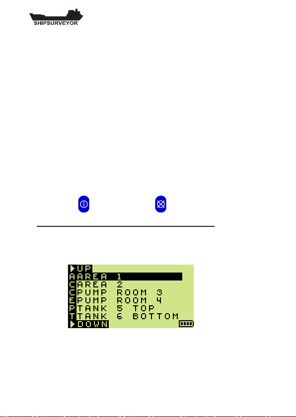
3.19.1 To select a location (LOC):
The location list can be accessed by simultaneously pressing
the Top Button and Bottom Button for two (2) seconds.
1. Location data already stored in the instrument:
If location data has previously been stored in the
instrument, it will now be displayed as illustrated in
Fig. 3-39.
3-28
Fig. 3-39 ‘LOC’ Display
Page 55

OPERATION
To select next entry in ‘LOC’ list :
• Press Bottom Button .
To quickly scroll down:
• Press and hold Bottom Button .
To select previous entry in ‘LOC’ list:
• Press Top Button .
To quickly scroll up:
• Press and hold Top Button .
If a location is highlighted and the user exits the location
(LOC) list, then that location will be associated with all
subsequent datalogging.
To exit ‘LOC’ list:
• Press and hold Top Button and Bottom Button
simultaneously for three seconds.
The instrument will return to displaying the gas
readings.
2. No Location data stored in the instrument:
If no location data has been stored in the instrument, the
display will be as illustrated in Fig. 3-40.
The instrument will still datalog, but no location data will be
associated with the stored readings.
3-29
Page 56

USER HANDBOOK
Fig. 3-40 ‘LOC’ Display
3.20 Acknowledge Alarms (CSM mode only)
The SHIPSURVEYOR default alarm function means that
instantaneous alarms will be latching and both the audible
and visual functions will operate. (Where an alarm level
is exceeded, the instrument LED’s ash and the sounder
pulses rapidly). Latching alarms must be cleared manually.
To clear a latching alarm:
• Press and hold the Bottom Button , for one
second, after the detected gas level has fallen below
the alarm limit. Refer to Chapter 4.4.1.
The option for the alarms is non-latching. These clear
automatically when the gas levels fall below the alarm limit.
The audible alarm can be muted.
To mute a non-latching alarm:
• Press and hold the Bottom Button for one
second. Refer to Chapter 4.4.3.
Note: An alarm remains muted until a new alarm
event occurs.
3-30
Page 57

OPERATION
3.21 Switch the instrument OFF
Before switching OFF from the normal operating mode, make
sure that the instrument is in fresh air in order to purge any
remaining gas from the instrument.
To initiate the shutdown sequence:
• Press and hold the Top Button .
The OFF sequence countdown begins and the user
must keep the buttons depressed for a further three
(3) seconds to switch the instrument OFF.
The countdown sequence is illustrated in Fig. 3-41.
Fig. 3-41 Countdown Sequence to OFF
Note 1: The OFF sequence can be aborted by
releasing the Top Button, providing access
to the previous operating display.
Note 2: The countdown sequence will commence at
‘9’ if an alarm is active when the shutdown
sequence is initiated.
3-31
Page 58

USER HANDBOOK
3.22 Button Operation Summary
3-32
Page 59

SHIPSURVEYOR
ALARM CONDITION (4 RED) LED's
and CONFIDENCE SIGNAL in CSM mode (outer 2 RED LED's)
POWER ON
(GREEN) LED
FAULT LED
(YELLOW)
4
ALARMS
4.1 Gas Alarms
The SHIPSURVEYOR alarms, by default, are enabled
when operating in Conned Space Monitor (CSM) mode
as indicated by an ‘A’ symbol in the top right corner of the
display. Both audible and visual alarms are active. The
audible alarm is rated up to 85 dB(A). The visual alarm
consists of two (2) pairs of red LED’s in the display panel as
illustrated in Fig. 4-1. When ashing, the red LED’s indicate
that the instrument is in alarm condition.
Fig. 4-1 Instrument Display Panel
4-1
Page 60

USER HANDBOOK
Alarm levels are set at the time of instrument manufacture.
It is important that the user ensures that the levels are in
accordance with their company’s alarm levels and with health
and safety legislation. The alarm levels are user congurable.
All gas ranges can have alarm limits that trigger the alarm if
the measured gas reading exceeds the set level. If a preset
alarm level is exceeded, the audible alarm sounds, the LED’s
ash, and the gas range name alternates with the alarm type.
Note: Alarms are disabled in Combustible Gas Indicator
(CGI) mode.
4.1.1 FLAMMABLE (LEL) ALARMS
Note: A congurable option allows the instrument to display
this range type as LFL (Lower Flammable Limit).
Two (2) instantaneous alarm levels (Hi and HiHi) are
congurable, each with different alarm indications, refer
to Fig. 4-1. Both are rising alarms, i.e. if the detected gas
concentration rises above the specic alarm level, the alarm
is triggered. All alarms are user congurable to meet the
needs of different companies.
4.1.2 OXYGEN (O2) ALARMS
Three (3) instantaneous alarm levels (HiHi, Lo and LoLo) are
congurable, each with different alarm indications, refer to
Fig. 4-1. These consist of one rising, and two falling alarms
(necessary to trigger alarms in oxygen decient scenarios).
All alarms are user congurable to meet the needs of different
companies.
4-2
Page 61

ALARMS
4.1.3 TOXIC ALARMS (e.g. CO)
Two (2) instantaneous alarm levels (Hi and HiHi) are
congurable, each with different alarm indications, refer
to Fig. 4-1. Both are rising alarms, i.e. if the detected gas
concentration rises above the specic alarm level, the alarm
is triggered. All alarms are user congurable to meet the
needs of different companies.
Additionally, two (2) Time Weighted Average (TWA) alarm
levels (STEL and LTEL) are configurable with alarm
indications, refer to Fig. 4-1.
Two (2) TWA alarms are congurable for each toxic range
within the instrument.
Note: A Time Weighted Average (TWA) value is the mean
average gas level over a specic period. The Short
Term Exposure Limit (STEL) is 15 minutes and the
Long Term Exposure Limit (LTEL) is 8 hours. The time
weighted averages are averaged over a full 24 hour
period whether the instrument is ON or OFF. Such
averaging essentially makes the instrument single
user applicable.
The option is available to restart the averaging after
each instrument switch-off, thus allowing for multiple
user application.
4-3
Page 62

USER HANDBOOK
4.2 Alarm Types
4.2.1 LATCHING / NON-LATCHING
Each alarm can be latching or non-latching.
Latching alarms can only be cleared by the user when the
gas level returns to within the alarm limits. A latching alarm
cannot be muted.
Non-latching alarms clear automatically when the gas level
returns to within the alarm limits. A non-latching alarm can
be muted.
4.2.2 MUTING / ACKNOWLEDGING
Muting of an alarm is achieved by a press and hold of the
Bottom Button. Muting means that the audible alarm is
cancelled. The audible alarm is reactivated if a new alarm
occurs.
Acknowledging is only applicable to latching alarms and
allows audible / visual alarms to be cancelled after the gas
readings have returned to safe concentrations.
4.3 Default Alarm Settings
Fig. 4-2, shows the GMI default selections. Latching or nonlatching options exist in all allowable alarms.
If an alarm is disabled (Dis), it will not function.
4-4
Page 63

4.3.1 Default Alarms Table
Alarm
Type
Level Latch D isplay Audible Vis ual
(RED LED's)
LE L Hi - Dis Hi 1 beep
per second
4 - slo w
flas hing
LEL Hi Hi 20% Y Hi Hi C ontinuo us
warble
Alternate pairs
flas hing
O
2
HiHi 23% Y Hi Hi C ontinuo us
warble
Alternate pairs
flas hing
O
2
Lo - Dis Lo 1 beep
per second
4 - slo w
flas hing
O
2
LoLo 19.5% Y LoLo C ontinuo us
warble
Alternate pairs
flas hing
H2S Hi - Dis Hi 1 beep
per second
4 - slo w
flas hing
H2S HiHi 15ppm Y HiHi Cont inuous
warble
Alternate pairs
flas hing
H2S STEL 10ppm N STEL 1 beep
per second
4 - slo w
flas hing
H2S LTEL 5ppm N LTEL 1 beep
per second
4 - slo w
flas hing
CO Hi - Dis Hi 1 beep
per second
4 - slo w
flas hing
CO Hi Hi 300ppm Y Hi Hi C ontinuo us
warble
Alternate pairs
flas hing
CO STEL 200ppm N STEL 1 beep
per second
4 - slo w
flas hing
CO LTE L 35ppm N LTEL 1 beep
per second
4 - slo w
flas hing
CO2 Hi - Dis Hi 1 beep
per second
4 - slo w
flas hing
CO2 HiHi 2.5% Y Hi Hi C ontinuo us
warble
Alternate pairs
flas hing
CO2 STEL 1.5% N STEL 1 beep
per second
4 - slo w
flas hing
CO2 LTEL 0.5% N LTE L 1 beep
per second
4 - slo w
flas hing
ALARMS
Fig. 4-2 Alarm Indication
4-5
Page 64

USER HANDBOOK
4.4 Alarm Examples
The following examples, in CSM mode, illustrate
the instrument’s display in various alarm conditions.
Examples are based on Default Alarm settings as
detailed in Fig. 4-2.
4.4.1 EXAMPLE 1 (LEL HiHi ALARM)
Fig. 4-3, illustrates a Shipsurveyor 1 instrument following a
‘HiHi’ alarm condition. The audible alarm emits a continuous
warble and the red LED’s ash in alternate pairs.
alternates with
Fig. 4-3 LEL HiHi Alarm
The alarm is latching, and therefore, can only be
acknowledged (cleared) by the user when the gas level
returns below the 20% LEL alarm limit.
4-6
Page 65

ALARMS
To clear the latching alarm:
• Press and hold ‘ACK’ (Bottom Button) for one
second.
4.4.2 EXAMPLE 2 (O2 LoLo ALARM)
This example, Fig. 4-4, illustrates a Shipsurveyor 2
instrument following a ‘LoLo’ alarm condition. The audible
alarm emits a continuous warble and the red LED’s ash in
alternate pairs.
alternates with
Fig. 4-4 O2 LoLo Alarm
The alarm is latching, and therefore, can only be cleared
by the user when the oxygen level rises above the 19.5%
O2 alarm limit.
4-7
Page 66

USER HANDBOOK
To clear the latching alarm:
• Press and hold ‘ACK’ (Bottom Button) for one
second.
4.4.3 EXAMPLE 3 (CO STEL ALARM)
This example, Fig. 4-5, illustrates a Shipsurveyor 5
instrument following an ‘STEL’ alarm condition. The audible
alarm beeps every second and all four (4) red LED’s ash
slowly.
alternates with
Fig. 4-5 CO STEL Alarm
The alarm is non-latching and therefore can be muted by the
user, and is reset automatically when the STEL level returns
below the 200ppm CO alarm limit.
4-8
Page 67

ALARMS
SHIPSURVEYOR
4 RED LED's - USED TO INDICATE FAULTS
POWER ON
(GREEN) LED
FAULT LED
(YELLOW)
To mute the non-latching alarm:
• Press and hold ‘MUTE’ (Bottom Button) for one
second.
4.5 Fault Alarms
The SHIPSURVEYOR instrument features a series of fault
alarms to alert the user that the instrument is not functioning
correctly. The audible and visual indications used are both
fault / type and mode (CSM or CGI) dependent.
Visual alarms are indicated by a series of LED’s, as illustrated
in Fig. 4-6. The power ON LED will remain illuminated during
all fault alarm indications.
Fig. 4-6 Instrument LED Panel
4-9
Page 68

USER HANDBOOK
Alarm Type
(CSM Mode)
Mute Display Audible V isual
(LED )
LOW
BATTE RY
No LO<>BAT
Co ntinuo us
To ne
Yellow &
4 Red
BATTE RY
EXHAUSTED
No BAT<>B AT
Co ntinuo us
To ne
Yellow &
4 Red
ZERO
FAULT
Ye s
Fla shi ng
Spanner
Co ntinuo us
To ne
Yellow &
4 Red
SENSOR
FAULT
No
Follo wing
Ranges Failed
Co ntinuo us
To ne
Yellow &
4 Red
FLOW
FAULT
No 'F LOW FA ULT'
Co ntinuo us
To ne
Yellow &
4 Red
IR SUPPLY
FAULT
No ' P '
Co ntinuo us
To ne
Yellow &
4 Red
COMMS.
FAULT
No ' I '
Co ntinuo us
To ne
Yellow &
4 Red
MEMORY
FAULT
No ' C '
Co ntinuo us
To ne
Yellow
4.5.1 Fault Alarms - CSM Mode
The following table, Fig. 4-7, illustrates the fault alarms in
CSM mode. Muting options exist in selected alarms.
4-10
Fig. 4-7 Fault Alarms in CSM Mode
Page 69

ALARMS
Alarm Type
(CGI Mo de)
Mute Display Audible Vis ual
(LED )
LOW
BATTE RY
No LO<>BAT No Yellow
BATTE RY
EXHAUSTED
No BAT<>B AT No Yellow
ZERO
FAULT
N/A
Fla shi ng
Spanner
No Yellow
SENSOR
FAULT
N/A
Follo wing
Ranges Failed
No Yellow
FLOW
FAULT
N/A 'F LOW FAULT' No Yellow
IR SUPPLY
FAULT
No ' P '
Co ntinuo us
To ne
Yellow &
4 Red
COMMS.
FAULT
No ' I '
Co ntinuo us
To ne
Yellow &
4 Red
MEMORY
FAULT
No ' C '
Co ntinuo us
To ne
Yellow
4.5.2 Fault Alarms - CGI Mode
The following table, Fig. 4-8, illustrates the fault alarms in
CGI mode. Muting options exist in selected alarms.
Fig. 4-8 CGI Mode Fault Alarms
4-11
Page 70

USER HANDBOOK
4.5.3 ZERO FAULT
If a zero fault occurs in CSM mode, the instrument’s audible
alarm will activate. The visual alarm (yellow and four red
LED’s) will also activate.
If a zero fault occurs in CGI mode, only the visual alarm
(yellow LED) will activate.
In both modes, a spanner symbol ashes in the display
adjacent to the corresponding gas type (H2S), as illustrated
in Shipsurveyor 3 example, Fig. 4-9.
alternates with
Fig. 4-9 Zero Fault
To correct the zero fault, switch the instrument OFF then ON
again in fresh air. If this does not correct the fault, return the
instrument for service.
4-12
Page 71

ALARMS
4.5.4 SENSOR FAULT
If a sensor fault occurs in CSM mode, the instrument’s
audible alarm will activate. The visual alarm (yellow and four
red LED’s) will also activate.
If a sensor fault occurs in CGI mode, only the visual alarm
(yellow LED) will activate.
In both modes, a warning display is followed by a display
showing a spanner symbol adjacent to the faulty range, as
illustrated in Shipsurveyor 3 example, Fig. 4-10.
Fig. 4-10 H2S Sensor Fault
The instrument should be returned for service.
4-13
Page 72

USER HANDBOOK
4.5.5 FLOW FAULT
A ow fault will occur if the ow path is restricted.
If a ow fault occurs in CSM mode, the instrument’s audible
alarm will activate. The visual alarm (yellow and four red
LED’s) will also activate.
If a ow fault occurs in CGI mode, only the visual alarm
(yellow LED) will activate and the instrument’s pump will
stop running.
In both modes, the FLOW FAULT display will alternate
between the two screens, illustrated in Fig. 4-11.
alternates with
Fig. 4-11 Flow Fault
4-14
Page 73

ALARMS
Follow the instructions as displayed, i.e.
- Check the ow path
- Remove the blockage
- Acknowledge the alarm
To acknowledge ow fault alarm:
• Press and hold ‘ACK’ (Bottom Button) for one
second.
4.5.6 MEMORY FAULT (Calibration /
Conguration)
During warm-up, if the ‘Calibration Required’ screen
is displayed as illustrated in Fig. 4-12, the instrument
has detected a calibration / conguration memory fault
and is unable to continue without re-calibration and / or
conguration set-up.
Fig. 4-12 Calibration / Conguration Memory Fault
The instrument must be returned for service.
4-15
Page 74

USER HANDBOOK
4.5.7 MEMORY FAULT (General Instrument)
At any time during operation, if a ‘C’ character is ashing
in the top RH corner of the display as illustrated in
Fig. 4-13, the instrument has detected a memory fault and
is unable to continue. The fault activates the audible alarm
and the (yellow) fault LED is illuminated.
Fig. 4-13 General Instrument Memory Fault
The instrument must be returned for service.
4.5.8 LOW BATTERY
During operation, ‘LO’ alternating with ‘BAT’ is displayed, as
illustrated in Fig. 4-14, when typically 30 minutes operating
time remains at normal temperature and depending on
battery type.
4-16
Fig. 4-14 LO-BAT
Page 75

ALARMS
In CSM mode, the instrument audible alarm will activate. The
visual alarm (yellow and four red LED’s) will also activate.
In CGI mode, only the visual alarm (yellow LED) will activate.
4.5.9 BATTERY EXHAUSTED
When ‘BAT’ ashes in the display, as shown in Fig. 4-15, the
instrument batteries are almost exhausted.
Fig. 4-15 BAT-BAT
In CSM mode, the instrument audible alarm will activate. The
visual alarm (yellow and four red LED’s) will also activate.
In CGI mode, only the visual alarm (yellow LED) will activate.
In both modes, the instrument automatically switches OFF.
The instrument batteries must be replaced.
(Refer to Chapter 5, ‘Operator Maintenance’).
4-17
Page 76

USER HANDBOOK
4-18
Page 77

5
OPERATOR MAINTENANCE
5.1 Batteries
The SHIPSURVEYOR contains two alkaline or rechargeable
batteries that provides the power required to operate the
instrument.
The alkaline batteries should be replaced, or the rechargeable
batteries recharged in the following situations:
• The‘LO-BAT’agisashinginthedisplay.
Indicates that the remaining operating time of the
instrument is low.
• The‘BAT’agisashinginthedisplay.
Indicates exhausted batteries and automatic switch-
off.
The procedure to remove / discard alkaline cells or to remove
rechargeable cells for charging is detailed in paragraph
5.1.1.Re-ttingofthecellsisalsoincludedinthisparagraph.
The rechargeable cells should be charged using a
commercialtypecharger.
5-1
Page 78

USER HANDBOOK
5.1.1 Replace Alkaline / Rechargeable Cells
WARNING 1: To prevent ignition of flammable or
combustible atmospheres, remove
batteries before servicing.
WARNING 2: To prevent ignition of flammable
or combustible atmospheres, read,
understand and adhere to the
manufacturer’s live maintenance
procedures.
WARNING 3: To reduce the risk of ignition of a
flammable or explosive atmosphere,
batteries must be changed only in a
location known to be non-hazardous
(safe area).
WARNING 4: To reduce the risk of explosion,
do not mix old batteries with new
batteries or mix batteries from different
manufacturers.
WARNING 5: Never attempt to recharge non
rechargeable cells.
5-2
Page 79
OPERATOR MAINTENANCE
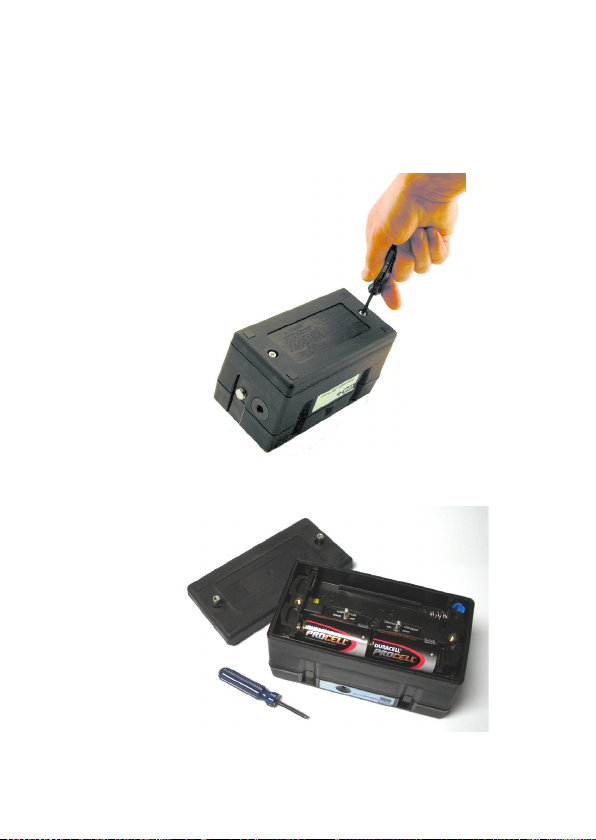
The following procedure shouldonlybecarriedoutin a
safe area:
1) Using the Hex Driver, loosen the two instrument base
screwsthenremovethebatterycover.
2) Removebatterycover.
5-3
Page 80

USER HANDBOOK
3) Remove the alkaline / rechargeable batteries.
4) Charge rechargeable batteries using a commercial
type charger.Charging duration is dependent on
chargertypeandconditionofrechargeablebatteries.
5) Check battery compartmentfordamagetospring
contacts or corrosion on springs.
6) Insert new alkaline / fully charged rechargeable
batteries, observing correct polarity indicationin
batterycompartmentbase.
7) Replacebatterycoverandfastenbothbasescrews.
8) Check that the instrument switches on and works to
specication.
5-4
Page 81

5.2 Filter Replacement
HYDROPHOBIC FILTER
PROBE HANDLE ASSEMBLY
COTTON PARTICULATE FILTER
5.2.1 Internal Filter
The SHIPSURVEYORinstrumenthasanintegralhydrophobic
ltertted.Toreplacethislter,refertoMaintenanceManual
(GMIPartNo.48166).
5.2.2 Probe Handle (Accessory) - Part No. 48120
Hydrophobicandcottonparticulateltersintheprobehandle
minimise the danger of water and dust ingress.
Toreplacethelter(s),proceedasfollows:
OPERATOR MAINTENANCE
1) Unscrewtheprobehandleassembly.
2) Removethecottonparticulatelteranddiscard.
3) Removethehydrophobiclter.
4) Clean the probe handle to make sure that it is free
from dirt and water.
5) Fitanewcottonparticulatelter.
6) Fit the hydrophobic lter. The yellowlabelonthe
filter fits againsttheyellowlabelon the probe
handle.
5-5
Page 82

USER HANDBOOK
7) Reassembletheprobehandleassembly.
5-6
Page 83

6
CALIBRATION
The instrument has been calibrated for a particular ammable
gas mixture. Where any doubt exists, the instrument should
be returned to GMI or an authorised distributor for calibration.
Three methods of calibration are possible:
• Field Calibration.
• Manual or Automatic Calibration using exiCal Plus
software CD-ROM (GMI Part No. 99553). CD-ROM
includes user instructions.
• The GMI Instrument Management System (IMS)
provides all the facilities of Automatic Calibration
with the added feature of instrument database
management.
Note: The calibration systems above (hardware and
software) are manufactured by GMI. For more details
contact GMI or an authorised distributor.
6-1
Page 84

USER HANDBOOK
6.1 Calibration Validity
Calibration validity is the responsibility of the user. Under
normal operating conditions a 12 month period can be
expected. This is no guarantee however, as the precise
application of the product is unknown to GMI. Individual
codes of practice may dictate shorter periods.
Regular checking establishes a pattern of reliability and
enables the calibration check period to be modied in line
with operational experience. The higher the risk, the more
frequently calibration should be checked.
6-2
Page 85

7
ACCESSORIES
Instrument complete with (c/w) Hard Case & Accessories:
48021 Shipsurveyor 1 (LEL ; Vol Gas)
48022 Shipsurveyor 2 (LEL ; Vol Gas ; O2)
48023 Shipsurveyor 3 (LEL ; Vol Gas ; O2 ; H2S)
48024 Shipsurveyor 4 (LEL ; Vol Gas ; O2 ; CO2)
48025 Shipsurveyor 5 (LEL ; Vol Gas ; O2 ; CO2 ; CO)
48026 Shipsurveyor 6 (LEL ; Vol Gas ; O2 ; H2S ; CO)
48027 Shipsurveyor 7 (O2 ; CO2)
48028 Shipsurveyor 8 (LEL ; Vol Gas ; O2 ; H2S ; CO2)
7-1
Page 86

USER HANDBOOK
Note: All Shipsurveyor instruments are supplied in a hard
Carry Case c/w: Neck / Shoulder Harness; 4mm Hex
Driver; Probe Handle c/w 1m (39ins.) Conductive Tubing;
15cm (6ins.) Open End Probe; Box (10) Cotton Filters x 2;
User Handbook; Quick Operating Instructions; Calibration
Certicate; Conguration Report; Datalogging & exiCal Plus
(Calibration) Software & IrDA Adaptor.
Accessories available for SHIPSURVEYOR:
Part Number Description
48100 Hard Carry Case
48101 Leather Field Case
12370 Neck / Shoulder Harness
12371 Waist Harness
48120 Probe Handle c/w 1m (39in.) Conductive
Tubing
12358 Hydrophobic Filter
10077 Cotton Filters (Box of 10)
12688 Sample Line Adaptor
12712 Clear Sample Line - per metre
48102 Ball Float
48142 Sample Line Adaptor c/w Waist
Harness, Quick Connect, and
Conductive Tubing x 10m (32ft.)
48145 Sample Line Adaptor c/w Waist
Harness, Quick Connect, and
Conductive Tubing x 25m (80ft.)
48147 Sample Line Adaptor c/w Waist
Harness, Quick Connect, and
Conductive Tubing x 35m (114ft.)
13427 35cm (14in.) Open End Probe
13413 35cm (14in.) S/Steel Open End Probe
12287 50cm (20in.) S/Steel Open End Probe
7-2
Page 87

ACCESSORIES
48110 Rechargeable Option Kit
(Charger, Universal Power Supply,
2 Rechargeable Batteries)
47280 Rechargeable Batteries x 2
48150 Data Downloading Package
99553 exiCal Plus Calibration Software
CD-ROM
48151 exiCal Plus Calibration Package
48160 Shipsurveyor User Handbook
48164 Shipsurveyor Conguration &. Field
Calibration User Handbook
48166 Shipsurveyor Maintenance
Manual
Note: For other sampling probes and accessories, contact
GMI Ltd.
7-3
Page 88

USER HANDBOOK
7-4
Page 89

8
ADDITIONAL INFORMATION
8.1 Training
Training courses are available on all GMI products. Contact
GMI Marketing Department for further details:
Tel: +44 (0) 141 812 3211
Fax: +44 (0) 141 812 7820
e-mail: sales@gmiuk.com
8.2 World Wide Web
Visit GMI web site at www.gmiuk.com
8-1
Page 90

USER HANDBOOK
8-2
Page 91

A
TYPICAL OPERATING
PARAMETERS
Typical operating parameters for the SHIPSURVEYOR
instrument are as follows:
Gas Range Resolution Accuracy
Range
LEL 0 to 9.9% 0.1% *
10 to 100% 1%
VOL 0 to 9.9% 0.1%
10 to 100% 1%
O2 0 to 20.9% 0.1%
21 to 25% 1%
H2S 0 to 100ppm 1ppm
CO2 0 to 5% 0.1%
5 to 20% 0.5%
CO 0 to 1000ppm 1ppm
* Congurable option, see page 2-2.
Notes:
All the values above are at normal temperature and pressure.
Humidity is between 0% and 100% RH (non-condensing).
Pressure changes at the inlet and exhaust should be minimised as they
may cause transient changes in reading.
+
2% / + 5% of reading
+
1% / + 5% of reading
+
0.1% / + 5% of reading
+
5% of reading
+
1ppm / + 5% of reading
+
0.1% / + 5% of reading
+
5% of reading
+
5ppm / + 5% of reading
A-1
Page 92

USER HANDBOOK
Dimensions
180mm (7.1in.) x 95mm (3.7in.) x 100mm (3.9in.)
Weight
1.35kg (3.0lb.) with two alkaline batteries
Operating Temperature
-20 oC to 50 oC (-4 oF to 122 oF)
Humidity
0 – 100% RH, non-condensing.
Construction
Moulded polypropylene case protected to IP54
Display
Dot Matrix LCD (128 x 64)
Warm-Up / Stabilization Time
~ 60 seconds
Typical Flow Rate Information
Nominal pump ow rate is 0.5 to 0.7 litres per minute.
Typical ow fail rate is 0.1 to 0.2 litres per minute.
Response Time (T90)
Typical O
response time (0.0 to 18.8% O
2
) > 15 seconds.
2
Power Source
Two ‘D’ size alkaline cells typically providing in excess of 20
hours runtime at 20oC (68oF).
or
Two ‘D’ size rechargeable cells typically providing in excess
of 8 hours runtime at 20oC (68oF).
A-2
Page 93

B
QUICK OPERATING INSTRUCTIONS
The following multi-language instructions provide the user
with a quick guide to the operation of the . . .
SHIPSURVEYOR instrument.
Each language and page reference is as follows:
• English - pages B-2 to B-6
B-1
Page 94

USER HANDBOOK
CHECKLIST
1. Check the instrument has no obvious faults.
2. Read and understand handbook before use.
3. Switch ON
4. Check battery levels.
5. Check “ZERO” in fresh air.
6. Check that the sample line and any accessories are in good
condition and leak free. Make sure that the instrument displays
a ow fault when the instrument inlet / sample line is blocked.
If fault is not displayed, check tightness of all ttings.
SAFETY
• The instrument must be regularly serviced and calibrated by fully
trained personnel in a safe area.
• Batteries: Alkaline or *Rechargeable batteries must be exchanged
(*and recharged) in a safe area and tted correctly before use.
Never use damaged batteries or expose to extreme heat.
See Chapter 5: OPERATOR MAINTENANCE.
• Only GMI replacement parts should be used.
• If the instrument detects gas, follow your own organisation’s
procedures and operational guidelines.
• The combustion chamber is a ameproof assembly and must not
be opened in the presence of a ammable atmosphere.
• Shipsurveyor instruments are certied as:
ATEX II 2 G Exd ia IIB T3 Gb (-20oC < Tamb < 50oC).
IEC Ex d ia IIB T3 (-20oC < Ta < +50oC)
• This equipment conforms to standard EN 50104.
• This equipment is also designed and manufactured to comply with
MED Directive 0038/YY (Module B&E). Further detail of the
Marine Equipment Directive, is located on the MED declaration of
conformity, supplied with the instrument.
Any right of claim relating to product liability or consequential damage to
any third party against GMI is removed if the warnings are not observed.
B-2
Page 95

QUICK OPERATING INSTRUCTIONS
WARNING: To prevent ignition of ammable or combustible atmospheres,
remove batteries before servicing.
WARNING: To prevent ignition of ammable or combustible atmospheres,
read, understand and adhere to the manufacturer’s live maintenance
procedures.
WARNING: To reduce the risk of ignition of a ammable or explosive
atmosphere, batteries must be changed only in a location known to be
non-hazardous.
WARNING: To reduce the risk of explosion, do not mix old batteries with
used batteries or mix batteries from different manufacturers.
WARNING: Never attempt to recharge non rechargeable cells.
CAUTION: Not for use in oxygen enriched atmospheres.
CAUTION: Replace batteries only with approved batteries, as follows:
ATEX Approved Instruments:
Alkaline (LR20 ‘D’ size): Duracell Procell; Duracell Industrial;
Duracell Plus; Energizer Ultra; Energizer Industrial.
Rechargeable (LR20 ‘D’ size): Uniross 2600mAh NiMH.
AREAS OF USE
Exposure to certain chemicals can result in a loss of sensitivity of the
ammable sensor (not applicable to infrared ammable sensor). Where such
environments are known or suspected it is recommended that more frequent
response checks are carried out. The chemical compounds that can cause
loss of sensitivity include Silicones, Lead, Halogens and Sulphur. Do not use
instrument in potentially hazardous atmospheres containing greater than
21% Oxygen. The enclosure material is carbon loaded polypropylene and
must not be exposed to environments which are liable to result in mechanical
or thermal degradation or to damage caused by contact with aggressive
substances. Additional protection may be required in environments where
the instrument enclosure is liable to damage.
English
B-3
Page 96

USER HANDBOOK
OPERATION
Switch ON
Press and hold either, Bottom Button
(CSM mode), or Top Button (CGI mode),
for one second, to switch the instrument and
pump ON in fresh air.
The instrument now begins its 60 second warm-up cycle, during which, a
countdown timer appears in the top right hand corner of the display.
The display backlight illuminates and remains ON until the warm-up cycle
is complete and then automatically switches OFF.
During the warm-up cycle, if congured, the instrument displays language
option then model, serial number, software version, datalogging, battery
status and calgas information as shown below.
The battery capacity level is displayed for approximately ve seconds
during the warm-up cycle, then on
the bottom RH corner of the display
during normal operation.
Next, the current time and date
is displayed. This is followed by
the Calibration Due Date then the
Service Due Date (if congured).
Each feature has ve congurable options:
1. Cal Due / Service Due message is not displayed.
2. Cal Due / Service Due date and overdue date messages are displayed.
3. Cal Due / Service Due message is displayed with user acknowledge
if expired.
4. Cal Due / Service Due message is displayed with user acknowledge for
extended period, if expired.
5. Cal Due / Service Due message is displayed with user shut-down, if
expired.
The next feature in the instrument warm-up cycle is sensor zeroing.
Finally, in CGI mode only and if congured, a ‘WARNING’ display alerts
the user that alarms are disabled in this mode and provides the option of
continuing operation or automatically switching the instrument off .
B-4
Page 97

QUICK OPERATING INSTRUCTIONS
On completion of the warm-up cycle,
the instrument will automatically
select, as default, the LEL range and
display the current gas detection
reading, as shown opposite.
Range Selection (CGI only)
To change range LEL-VOL GAS-LEL, single press the ‘RANGE’ Top Btn .
Switch Pump OFF / ON (CGI only)
Press and hold ‘PUMP’ Bottom Button to switch the pump OFF / ON.
Zero All Ranges (CGI only) in Fresh Air
Press and hold Bottom Button for approximately ve (5) seconds.
Then, press and hold ‘YES’ (Top Button) for one second to zero all ranges
and return to live readings.
Manual Datalogging
To store a snapshot reading, press and hold ‘STORE’ (Top Button) .
Max / Min Values
To display max. value since switch-on, press ‘MAX’ (Bottom Button) .
To display min. value since switch-on, press ‘MIN’ (Bottom Button) .
Note: ‘MIN’ Only applicable to instruments with Oxygen (O2) sensor tted.
English
To erase Max / Min values, press and hold ‘CLEAR’ (Top Button) .
To return to live readings, press and hold ‘LIVE’ (Bottom Button) .
B-5
Page 98

USER HANDBOOK
Enter (LOC) Location List
Press and hold Top Button and Bottom Button simultaneously.
To select next entry in LOC list, press ‘DOWN’ (Bottom Button) .
To scroll through next entries in LOC list, press and hold ‘DOWN’
(Bottom Button)
To select previous entry in LOC list, press ‘UP’ (Top Button) .
To scroll through previous entries in LOC list, press and hold ‘UP’
(Top Button) .
To select location and exit LOC list, press and hold Top Button
and Bottom Button simultaneously. Note that ‘LOC’ names must
be pre-loaded.
.
Acknowledge Alarms (CSM only)
To clear a latching alarm, press and hold ‘ACK’ (Bottom Button) after
the detected gas level has fallen below the alarm limit.
To mute a non-latching alarm, press and hold ‘MUTE’ (Bottom Button) .
Switch OFF
Press and hold the Top Button . Keep button depressed while OFF
sequence countdown completes.
B-6
Page 99

INDEX
A
ACCESSORIES 7-1
Acknowledge Alarms
(CSM mode only) 3-30
Acknowledging 4-4
ADDITIONAL INFORMATION
8-1
Alarms 2-7
ALARMS 4-1
Alarms, Acknowledge 3-30
Alarms (CSM mode only) 3-22
Alarms, Default 4-5
Alarm Settings 4-4
Alarms, Fault 4-9
Alarms in CGI Mode 4-11
Alarms in CSM Mode 4-10
Alarm Warning (CGI mode only)
3-21
alkaline A-2
AREAS OF USE iii
B
Batteries 2-8
BATTERY EXHAUSTED 4-17
BATTERY, LOW 4-16
Battery Replacement
4-4, 4-6, 5-1
Before Use Checks 2-10
Button Operation Summary 3-32
Buttons, Operating 3-2
C
CAL DUE 3-6
CALIBRATION 6-1
Calibration Due Date 3-6, 3-12
Calibration Validity 6-2
Carbon Dioxide (CO2),
0 to 20% 2-4
Carbon Monoxide (CO),
0 to 1000ppm 2-5
CGI 3-3
CGI Mode 3-25, 4-11
Combustible Gas Indicator
(CGI) Operation 2-6
Conned Space Monitor
(CSM) Operation 2-6
Conrmation, Sensor 3-18
Construction 2-8, A-2
COPYRIGHT i
CO STEL ALARM 4-8
CSM 3-3
CSM Mode 4-10
D
Datalogging 2-7, 3-24
Date 3-6
Default Alarms 4-5
Default Alarms Table 4-5
Details of Operating Ranges
2-2
Display A-2
DISPOSAL ADVICE ii
DUE, CAL 3-6
DUE, SERVICE 3-12
I
Page 100

USER HANDBOOK
E
English B-1
EXHAUSTED, BATTERY 4-17
F
FAIL, FLOW 4-14
Fault Alarms 4-9
FAULT, MEMORY 4-15, 4-16
FAULT, SENSOR 4-12, 4-13
Fault, Zero 3-18
features 1-2
Features, Instrument 3-1
Filter, Internal 5-5
Filters 2-9
Filter(s) Replacement 5-5
FLAMMABLE (LEL) ALARMS
4-2
FLOW FAIL 4-14
Flow Rate Information A-2
G
GENERAL INFORMATION 2-1
H
Handle, Probe 3-3, 5-5
HANDLING iii
Humidity A-2
Hydrogen Sulphide (H2S),
0 to 100ppm 2-4
I
Identication, Instrument 3-5
IMS 6-1
INFORMATION, ADDITIONAL
8-1
INFORMATION, GENERAL
2-1
INSTRUCTIONS, OPERATING
B-1
Instrument Features 3-1
Instrument Identication 3-5
Instrument Models / Ranges
2-1
Instrument Will Not Zero -
Gas Present 3-20
Instrument Will Not Zero -
Zero Fault 3-18
Internal Filter 5-5
INTRODUCTION 1-1
L
Language Option 3-4
Latching 4-4
LCD A-2
LEL 2-2
LEL HiHi ALARM 4-6
LIABILITY i
Liquid Crystal Display (LCD)
2-9
Location (LOC) Selector 3-28
LOW BATTERY 4-16
M
MAINTENANCE, OPERATOR
5-1
Max / Min Values 2-8, 3-25
II
 Loading...