

Page 1

Personal Surveyor 200
Gas Measurement Instruments Ltd
User Handbook
Page 2

Issue 8
12/10/2016
Part Number: 64171
GMI welcomes comments on all our publications. Your
comments can be of great value in helping us to improve
our customer publications. Please send any comments
that you have to customerservice@gmiuk.com
Copyright © Gas Measurement Instruments Ltd 2012
Page 3

COPYRIGHT
COPYRIGHT
This User Handbook is copyright of Gas Measurement Instruments Ltd (GMI) and
the information contained within is for use only with the GMI Personal Surveyor 200
(PS200) series instruments. Reproduction, in whole or in part, including utilisation
in machines capable of reproduction or retrieval without written permission of GMI
is prohibited. Reverse engineering is not permitted.
LIABILITY
Every care has been taken in the preparation of this Handbook, but GMI do
not accept any responsibility for errors or omissions and their consequences.
Information in this Handbook is subject to change without notice. This Handbook
does not constitute a specication or basis for a contract. Your statutory rights
under law are not affected.
MODIFICATION NOTICES
GMI aim to notify customers of relevant changes in the product operation and
maintain this Handbook up to date. In view of the policy of continuous product
improvement there may be operational differences between the latest product
and this Handbook.
This Handbook is an important part of the PS200 product.
Please note the following points:
• It should be kept with the instrument for the life of the product
• This Handbook should be passed on to any subsequent owner / user of
the instrument
• Although every care is taken in the preparation of this Handbook, it does
not constitute a specication for the instrument.
SOFTWARE
Software supplied on micro-controller or similar device for use in a particular
product, may only be used in that product and may not be copied without the written
permission of GMI. Reproduction or disassembly of such embodied programmes
or algorithms is prohibited. Ownership of such software is not transferable and
GMI does not warrant that the operation of the software will be error free or that
the software will meet the customer’s requirements.
DISPOSAL ADVICE
When no longer in use, dispose of the instrument carefully and with respect for
the environment. Refer to WEEE directive statement, such as:
In compliance with the WEEE directive, GMI will dispose of the instrument without
charge if the instrument is returned to GMI.
i
Page 4

USER HANDBOOK
SAFETY
• The instrument must be regularly serviced and calibrated by fully trained
personnel in a safe area thus user adjustment is not required.
• Replacement or charging of the equipment is only permitted in a non hazardous area.
• Only GMI replacement parts should be used.
• Instrument must be re-charged in a safe area before use. Refer to
Chapter 6 : ‘RECHARGE BATTERY’.
• If the instrument detects gas, follow your own organisation’s procedures
and operational guidelines.
• Gas can be dangerous and care should always be taken in its use.
• This equipment is designed and manufactured to protect against other
hazards as dened in ATEX Directive 94/9/EC.
Any right of claim relating to product liability or consequential damage to any third
party against GMI is removed if the above warnings are not observed.
ADDITIONAL SAFETY DETAILS - CSA ONLY
CAUTION: Before each days Usage, test on a known concentration of methane,
equivalent to 25 - 50% of full scale concentration. Accuracy must be within
0 to +20% of actual. Accuracy may be corrected by calibration. (Refer to
Chapter 7 : ‘CALIBRATION’).
ATTENTION: Avant chaque utilisation journalière, testez la réaction de l’appareil
en utilisant une concentration connue en méthane, correspondant à 25-50%
de la lecture à fond d’échelle. La précision doit se situer entre 0 et +20% de la
valeur réelle. La précision peut se corriger en étalonnant l’appareil (voir Chapitre
7 : CALIBRATION).
CAUTION: Any rapid up-scale readings followed by a declining or erratic reading
may indicate a gas concentration beyond the upper scale limit, which may be
hazardous.
ATTENTION: Toute lecture dépassant rapidement le maximum de l’échelle et
suivie par une diminution ou une lecture erronée, indique une concentration de
gaz supérieure à la valeur maximale de cette échelle. Cette lecture n’est pas
signicative.
CAUTION: Substitution of components may impair intrinsic safety.
ATTENTION: le remplacement d’un composant peut porter atteinte à la sécurité
intrinsèque du produit.
CAUTION: Do not charge in a hazardous area. Um = 6V.
ATTENTION: Ne pas charger en zone dangereuse. Um = 6V.
NOTE: CSA have only assessed the LEL combustible gas detection portion of
this instrument for performance.
ii
Page 5

COPYRIGHT
NOTE : CSA a seulement évalué la partie LIE pour la mesure des performances
en détection de gaz inammables.
NOTE: The instrument contains internal checking of sensor sensitivity, which during
calibration will prevent the sensor being calibrated if it has been contaminated
or reached its end of life. In addition to this the Instrument Management System
(IMS) can be used to track the condition of sensors from stored calibration results.
AREAS OF USE
Exposure to certain chemicals can result in a loss of sensitivity of the ammable
sensor. Where such environments are known or suspected it is recommended that
more frequent response checks are carried out. (Refer to Chapter 3: ‘MANUAL
BUMP TEST’). Chemical compounds that can cause loss of sensitivity include
Silicones, Lead, Halogens and Sulphur.
Do not use instrument in potentially hazardous atmospheres containing greater
than 21% Oxygen.
SPECIAL CONDITIONS OF USE
No precautions against electrostatic discharge are necessary for portable
equipment that has an enclosure made of plastic, metal or a combination of the
two, except where a signicant static generating mechanism has been identied.
Activities such as placing the item in a pocket or on a belt, operating a keypad
or cleaning with a damp cloth, do not present a signicant electrostatic risk.
However, where a static-generating mechanism is identied, such as repeated
brushing against clothing, then suitable precautions shall be taken, e.g. the use
of anti-static footwear.
STORAGE, HANDLING AND TRANSIT
The instrument is designed to handle harsh environments. The instrument is
sealed to IP67 and, if not subjected to misuse or malicious damage, will provide
many years of reliable service.
The instrument can contain electrochemical sensors. Under conditions of prolonged
storage these sensors should be removed. The sensor contains potentially
corrosive liquid and care should be taken when handling or disposing of the sensor,
particularly when a leak is suspected.
WARRANTY
The GMI PS200 instrument has a standard warranty of 2 years against faulty
consumable, mechanical and electronic parts, e.g. pump, sensors, lters, battery,
exi-PCB etc.
For further details, please contact GMI.
Please note however, that the warranty does not include damage caused by
misuse, e.g. mechanical impact or water ingress and provided that any service or
calibration work has been carried out by the manufacturer or authorised agent.
iii
Page 6

USER HANDBOOK
iv
Page 7

CONTENTS
COPYRIGHT i
LIABILITY i
MODIFICATION NOTICES i
SOFTWARE i
DISPOSAL ADVICE i
SAFETY ii
AREAS OF USE iii
SPECIAL CONDITIONS OF USE iii
STORAGE, HANDLING AND TRANSIT iii
WARRANTY iii
INTRODUCTION 1-1
1.1 GENERAL DESCRIPTION 1-1
1.2 FEATURES 1-4
1.3 DATA LOGGING 1-5
1.3.1 Archiving Stored Readings 1-6
1.4 FILTERS 1-6
1.5 CONSTRUCTION 1-6
1.6 IDENTIFICATION LABEL 1-6
v
Page 8

USER HANDBOOK
1.7 CERTIFICATION 1-7
1.7.1 Certication Marks 1-8
1.7.2 Performance 1-8
OPERATION 2-1
2.1 OPERATING PROCEDURE 2-1
2.2 SWITCH THE INSTRUMENT ON 2-2
2.2.1 Instrument Identication 2-3
2.2.2 Battery Status 2-3
2.2.3 User Name / Number Only (Option) 2-4
2.2.4 Date and Time 2-4
2.2.5 Bump Due Date (Option) 2-5
2.2.6 Calibration Due Date 2-6
2.2.7 Service Due Date (Option) 2-7
2.2.8 Select Calibration Gas (Option) 2-8
2.2.9 Sensor Conrmation Check 2-9
2.2.10 Memory Fault 2-11
2.2.11 Normal Operating Display 2-11
2.3 SWITCH THE DISPLAY BACKLIGHT ON / OFF 2-12
2.4 MANUAL DATALOG 2-12
2.5 VIEW MAXIMUM AND MINIMUM RECORDED
VALUES SINCE SWITCH ON 2-12
2.6 ALARMS RESET OR ACKNOWLEDGE 2-15
2.6.1 Condence Signal 2-15
2.7 REMOTE SAMPLING (with pump option) 2-16
2.7.1 Pump Operation: 2-16
vi
Page 9

CONTENTS
2.8 SELF TEST 2-17
2.9 SWITCH THE INSTRUMENT OFF 2-18
MANUAL BUMP TEST OPTIONS 3-1
3.1 BACKGROUND 3-1
3.2 MANUAL BUMP OPTIONS 3-2
3.3 INITIATING A MANUAL BUMP TEST 3-2
3.3.1 Regulator Valve Selection
(Pumped Instrument Only) 3-3
3.4 APPLYING TEST GAS 3-4
3.5 QUICK / FULL BUMP TEST 3-4
3.5.1 Quick Bump Test 3-4
3.5.2 Full Bump Test 3-4
3.6 ALARM CONFIRMATION 3-5
3.7 BUMP TEST RESULT 3-5
ALARMS 4-1
4.1 GAS ALARMS 4-1
4.1.1 Flammable LEL Alarm Limit 4-3
4.1.2 Over-Range Flammable Gas Alarm Function 4-3
4.1.3 Oxygen (O2) Alarm Limits 4-3
4.1.4 Toxic Alarm Limits 4-3
4.2 ACKNOWLEDGE GAS ALARMS 4-5
4.3 MUTE ALARMS 4-5
4.4 HIGH FLAMMABLE GAS OVER-RANGE ALARM 4-5
vii
Page 10

USER HANDBOOK
4.5 FAULT ALARMS 4-7
4.5.1 Low Battery 4-7
4.5.2 Zero Fault 4-8
4.5.3 Sensor Fault 4-9
4.5.4 Flow Fault (Pumped Instruments Only) 4-11
4.5.5 Calibration Required 4-12
4.5.6 Calibration Expired 4-13
OPERATOR MAINTENANCE 5-1
5.1 CLEANING 5-1
5.2 REPLACE INSTRUMENT FILTERS 5-1
5.2.1 Replace Sensor Hydrophobic Filter 5-2
5.2.2 Replace Sample Inlet (Dust) Filter 5-3
5.2.3 In-line Hydrophobic Filter (Accessory) 5-4
RECHARGE BATTERY 6-1
6.1 RECHARGE INSTRUMENT BATTERY 6-1
6.1.1 Recharge Instrument using the Charging /
Comms Clip 6-2
6.1.2 Recharge Instrument using the 5-way Charger
6-4
6.1.3 Recharge Instrument using the 12V / 24V
In-Vehicle Charging Adaptor 6-5
6.1.4 Recharge Instrument using the In-Vehicle
Charging Cradle 6-7
viii
Page 11

CONTENTS
CALIBRATION 7-1
7.1 GENERAL DESCRIPTION 7-1
7.2 CALIBRATION VALIDITY 7-2
ACCESSORIES 8-1
ADDITIONAL INFORMATION 9-1
9.1 TRAINING 9-1
9.2 WEBSITE 9-1
TYPICAL OPERATING PARAMETERS A-1
PHYSICAL PROPERTIES A-1
ENVIRONMENT A-1
TYPICAL FLOW RATE INFORMATION A-2
WARM-UP / STABILIZATION TIME A-2
ALARMS A-2
DISPLAY A-2
POWER SOURCE A-2
CONSTRUCTION A-2
IP RATING A-2
RESPONSE TIMES (T90) A-2
ix
Page 12

USER HANDBOOK
LEL SENSOR TYPES B-1
INDEX i
x
Page 13

1
INTRODUCTION
1.1 GENERAL DESCRIPTION
The GMI PS200 series combines quality, ruggedness and
advanced technology in a user friendly, portable gas detector.
It is compact, lightweight, water resistant, extremely robust
and is suitably certied to recognised International Standards.
The PS200 is designed for conned space monitoring, for
example, in sewers, underground piping, or within tanks and
other personal monitoring applications. With audible, visual
and vibrating alarms, it provides early warning of dangerous
gas levels.
The instrument is available as either a pumped or diffusion
model and is powered by an internal Li-ion (lithium ion)
rechargeable battery with an operating time of up to 80 hours
for non-pumped operation (20 hours for pumped operation).
Operating time is sensor dependent. Maximum recharge
time is 4 hours.
Operated via two push buttons, this instrument provides the
user with a simple to use, yet state-of-the-art, gas detector.
(Fig. 1-1).
The PS200 series features high visibility LED’s, a display that
changes colour from green to red when an alarm is present,
a sounder with a 90dB minimum output and a vibrating
alarm. Users can be condent that, should gas levels exceed
congured threshold limits or a sensor / ow / battery fault
exists, a clear and unmistakeable indication is evident.
1-1
Page 14

USER HANDBOOK
Fig. 1-1 PS200 Series Instrument
The PS200 Series has the ability to detect up to four (4) of the
following gases simultaneously:
• 0 to 100% LEL Hydrocarbons
• 0 to 25% Oxygen (O2)
• 0 to 1000ppm Carbon Monoxide (CO)
• 0 to 100ppm Hydrogen Sulphide (H2S)
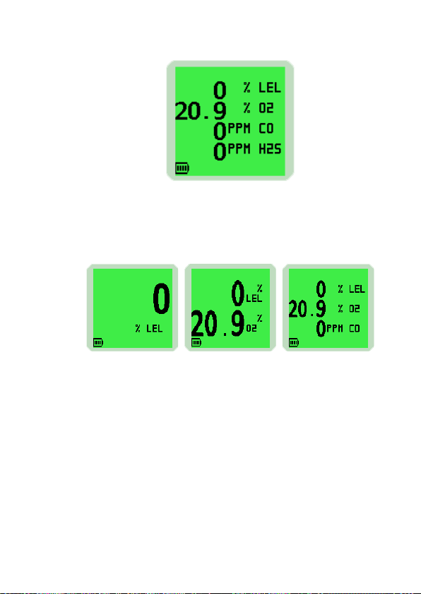
The instrument display identies the gas(es) the instrument
is monitoring. An example of a four gas instrument display is
illustrated in Fig. 1-2.
1-2
Page 15
INTRODUCTION
Fig. 1-2 Display Example (4-Gas)
Note: If congured with less sensors, the character size is
adjusted accordingly to maximise the display, as illustrated
in Fig. 1-3.
1-Gas 2-Gas 3-Gas
Fig. 1-3 Display Examples
The display, illustrated in Fig’s 1-2 and 1-3, details the current
gas readings and operational / status information. Alternatively,
the instrument can be set up to display a simple ‘OK’ message,
as illustrated in Fig. 1-4.
1-3
Page 16

USER HANDBOOK
Fig. 1-4 ‘OK’ Display Example (4-Gas)
Note: This Handbook describes the operation of a standard
4-gas instrument. On other models, operation is similar to the
example shown. Operational differences are highlighted if and
where they exist. Congurable options are available that allow
the instrument to be set up to suit your particular requirements.
These options are detailed in italic text, where applicable.
1.2 FEATURES
The main features of the PS200 series instrument are:
• Compact, lightweight and extremely robust.
• Simultaneous detection and display of up to four (4)
gases.
• Simple 2 button operation.
• Clear audible, visual (hi-viz) ashing LED’s and vibrating
alarms.
• Audible and visual condence signal (fully congurable)
every 15 seconds, confirming to the user that the
instrument is correctly energised and operating normally.
1-4
Page 17

INTRODUCTION
• Alphanumeric display with screen backlighting.
Backlighting is coloured green during normal operation
and red during alarm condition.
• Internal electric pump (optional) with a nominal ow rate
of 0.5 to 0.7 litres per minute.
• Both manual and fully automatic data logging.
• Powered by an internal Li-Ion (Lithium Ion) rechargeable
battery, this will provide an operating time of up to:
14 hours (non-pumped) or 8 hours (pumped)
or
80 hours (non-pumped) or 20 hours (pumped)
When tted with the SGX VQ548MP sensor.
• Recharge time is up to 4 hours.
• Robust alligator clip to allow tting to belt, pocket, etc.
• Communications interface to allow downloading of
stored data.
• Fully certied to international standards.
• Comprehensive range of accessories available.
‘TYPICAL OPERATING PARAMETERS’ are detailed in
Appendix ‘A’ of this Handbook.
1.3 DATA LOGGING
Data logging is a standard feature of all PS200 series
instruments and allows gas measurements, event logs, bump
tests and calibration details to be automatically stored and
later downloaded to a Personal Computer (PC) via a USB
connection.
The instrument can store in excess of 24 hours of readings at
a recording interval of 1 minute, 180 On / Off event logs and
alarms, 180 bump test logs and 8 calibrations.
1-5
Page 18

USER HANDBOOK
1.3.1 Archiving Stored Readings
Stored readings can be downloaded from the PS200 series
instrument to a PC, using the standard charging / comms cable
and additional software. Contact the GMI Sales Department
for further details.
1.4 FILTERS
The instrument is protected from water and dust ingress by
hydrophobic and dust (sample inlet) lters.
These lters should be checked regularly and replaced if
necessary (refer to ‘FILTER REPLACEMENT’ section in
Chapter 5 ‘OPERATOR MAINTENANCE’).
1.5 CONSTRUCTION
The PS200 series is housed in a tough, impact resistant
moulded case. Sealed to IP67, it can withstand physical impact
testing to EN 60079 section 1-5.
1.6 IDENTIFICATION LABEL
The label on the rear of the instrument includes serial number
and relevant certication details.
1-6
Page 19
INTRODUCTION
1.7 CERTIFICATION
The PS200 series instrument is certified as follows:
Note: Check instrument labels for actual certication.
ATEX II 2G Ex ia d IIC T4 Gb (Ta = -20oC to +50oC)
IECEx Ex ia d IIC T4 Gb (Ta = -20oC to +50oC)
or
ATEX II 1G Ex ia IIC T4 Ga (Ta = -20oC to +50oC)
IECEx Ex ia IIC T4 Ga (Ta = -20oC to +50oC)
(when tted with the SGX VQ548MP sensor)
Combustible Instruments:
Class I, Div.1 Groups A, B, C and D T4
Class I, Zone 1 AEx ia d IIC T4 Gb Ex ia d IIC T4 Gb
or
Class I, Div.1 Groups C and D T4
Class I, Zone 0 AEx ia IIB T4 Ga Ex ia IIB T4 Ga
(when tted with the SGX VQ548MP sensor)
Non-combustible Instruments:
Class I, Div.1 Groups A, B, C and D T4
Class I, Zone 0 AEx ia IIC T4 Ga Ex ia IIC T4 Ga
MED (Marine Equipment Directive) - A.1 / 3.30
0038/YY (Module B&E)
0518 European Mark of Conformity
1-7
Page 20

USER HANDBOOK
OCP 0017
Segurança
ATENÇÃO: NÃO RECARREGAR
EM AREA CLASSIFICADA
DNV 16.0082 X Um=6V
14-AV4BO-0010
Ex ia d IIC T4 Gb (Ta = -20oC to +50oC)
IECEx SIR11.0019
TP TC 012/2011
TP TC 020/2011
1.7.1 Certication Marks
Refer to the following for details:
www.europe.eu.atex
www.iecex.com
1.7.2 Performance
This apparatus conforms to standard EN 50104.
Complies with:
EN 60079-29-1 (Flammable)
IEC 60079-29-1 (Flammable)
EN 50104:2010 (Oxygen)
ANSI / ISA S12.13.01 - 2000 (Combustible)
C22.2 No.152 - M1984 (Combustible)
1-8
Page 21

OPERATION
2.1 OPERATING PROCEDURE
2
CAUTION: The GMI PS200 instrument can be supplied with
Check the following before use:
• The PS200 instrument is clean and in good condition.
• The hydrophobic and inlet lters are clean and in good
• The sample line (pumped instruments) and any other
• Switch instrument ON in fresh air and check that the
• Verify there are no faults.
• Attach optional accessories, as required.
• All gas ranges are operational and the instrument is
a ammable gas sensor. This sensor is designed
for use in concentrations of gas not exceeding
the Lower Explosive Limit (LEL). Exposing the
sensor to high concentrations of ammable gas
above the LEL can cause damage to the sensor
and inhibit its proper operation. The GMI PS200
has an inbuilt safety alarm feature to prevent
this. Refer to ALARMS section of this handbook
for details.
condition.
accessories used are in good condition and leak-free.
battery is fully charged.
zeroed.
2-1
Page 22

USER HANDBOOK
• The instrument is within the calibration period you have
decided is necessary for your application.
• If oxygen sensor is tted, check oxygen readings to
ensure correct operation. The oxygen sensor responds
to the user breathing on the instrument front face (sensor
area) by displaying a decreased value, i.e. below 20.9%.
Switch the instrument OFF, in fresh air, after use.
Additional:
• Perform regular leak check on pumped instruments, by
placing thumb over sample inlet nozzle and making sure
that instrument displays ‘FLOW FAULT’.
• Perform regular bump tests using either the Auto Bump
/ Calibration Station or by performing manual bump tests.
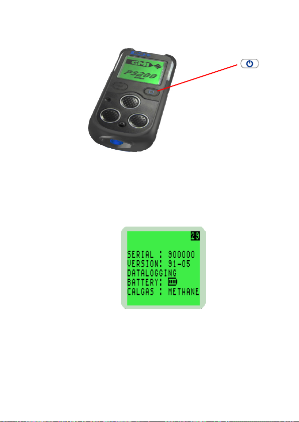
2.2 SWITCH THE INSTRUMENT ON
Press and hold the Right Hand (RH) button for one
second to switch the instrument ON. Refer to Fig. 2-1.
The instrument begins its warm-up routine, which lasts
approximately 30 seconds. During the warm-up, a countdown
timer appears in the top (RH) corner of the display.
Note: The display backlight illuminates green and remains
ON during warm-up. When warm-up is complete, the screen
light automatically switches off.
2-2
Page 23
OPERATION
RIGHT HAND (RH)
BUTTON
Fig. 2-1 PS200 Switch ON
2.2.1 Instrument Identication
During warm-up, the instrument display identies the serial
number, software version and battery status information as
illustrated in Fig. 2-2:
Fig. 2-2 PS200 Series Identication Display
2.2.2 Battery Status
Provides the user with the battery charge level, as shown in
previous display. This will be indicated by a battery symbol
with a bar graph showing FULL, 75%, 50% and 25%, which
is shown continually during normal operation.
2-3
Page 24
USER HANDBOOK
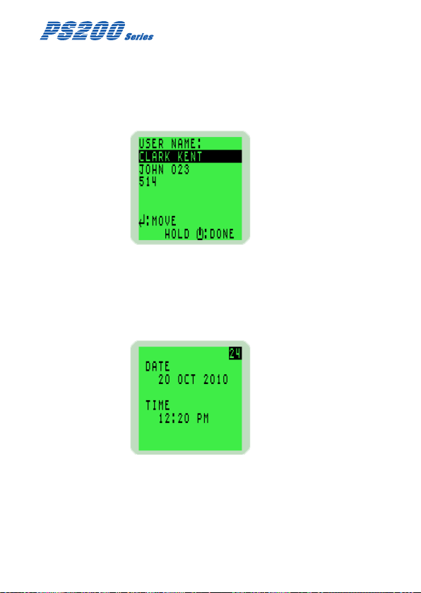
2.2.3 User Name / Number Only (Option)
This congurable option, disabled by default, allows the user
to select a name or identication code, as illustrated in Fig.
2-3. This name or code will be included with all Bump,
Calibration and Event logs.
Fig. 2-3 User Name
2.2.4 Date and Time
The date and time from the instrument’s built-in clock is
displayed on the screen during warm-up, as illustrated in
Fig. 2-4.
2-4
Fig. 2-4 Date and Time
Page 25
OPERATION
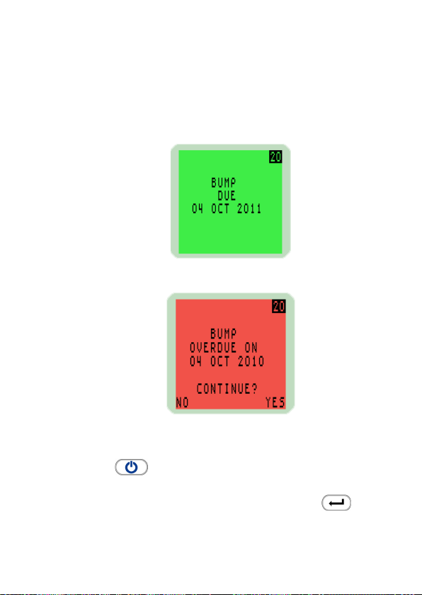
2.2.5 Bump Due Date (Option)
This congurable option is disabled by default but can be
congured to either, indicate briey that bump test is due, as
illustrated in Fig. 2-5, indicate that bump test is overdue then
pause awaiting user acceptance, as illustrated in Fig. 2-6, or
force the user to switch instrument OFF when overdue.
Fig. 2-5 Bump Due Date
Fig. 2-6 Bump Overdue
To continue instrument operation, press the Right Hand (RH)
button once to acknowledge bump test is overdue.
To abort the warm-up routine and automatically switch the
instrument OFF, press the Left Hand (LH) button once.
2-5
Page 26
USER HANDBOOK
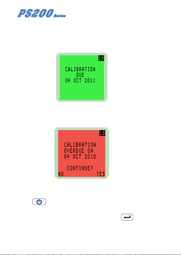
2.2.6 Calibration Due Date
The calibration due date appears on the display, as illustrated
in Fig. 2-7.
A congurable option is available not to display this screen.
Fig. 2-7 Calibration Due Date
If the Calibration Due Date has expired, the following warning
is displayed:
Fig. 2-8 Calibration Overdue
To continue instrument operation, press the Right Hand (RH)
button once to acknowledge calibration is overdue.
To abort the warm-up routine and automatically switch the
instrument OFF, press the Left Hand (LH) button once.
2-6
Page 27

OPERATION
Alternatively, a congurable option is available to force the
user to switch the instrument OFF.
2.2.7 Service Due Date (Option)
This congurable option, disabled by default, allows the user
to select from a number of options listed, when the service
date expires on the instrument.
In all instances, if enabled, message is only displayed if within
90 days of service due date.
• To indicate the service due date briey during instrument
warm-up routine.
• To indicate that service is overdue then pause awaiting
user acceptance, or rejection, to continue.
• To force the user to switch the instrument OFF when
service is overdue.
The service due date appears on the display, as illustrated
in Fig. 2-9.
Fig. 2-9 Service Due Date
2-7
Page 28
USER HANDBOOK
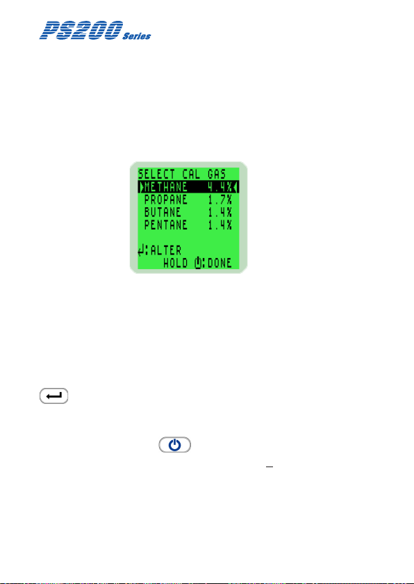
2.2.8 Select Calibration Gas (Option)
This congurable option is available to allow the user to
measure a different ammable gas from that which was
originally used to calibrate the instrument.
This action allows the instrument software to compensate and
display more accurate readings.
The default is to select calibration gas at ‘Setup’.
Fig. 2-10 Cal Gas Selection
When this option is displayed, as shown in Fig. 2-10, the gas
that was originally used to calibrate the instrument is identied
between two arrowheads.
Note: The instrument calibration certicate also identies the
original calibration gas type.
To select a different gas type, press the Left Hand (LH) button
to step through the available options from Methane,
Propane, Butane and Pentane.
When the required option is highlighted, press and hold the
Right Hand (RH) button to select.
Note: Accuracy for the re-selected gas type is + 20%.
2-8
Page 29

OPERATION
2.2.9 Sensor Conrmation Check
The symbol appears adjacent to each sensor type to
conrm that the sensor has been zeroed correctly.
Fig. 2-11 Sensor Check Displays
If a sensor fails to zero correctly, the display will be red, the
audible / visual alarms activate and a symbol is displayed
adjacent to the faulty gas type, as illustrated in Fig. 2-12:
Fig. 2-12 Failed Sensor
To acknowledge this fault, press the Right Hand (RH) button
once. This will clear the audible / visual alarm and
display a ashing spanner symbol alternating with the faulty
sensor zero reading.
2-9
Page 30

USER HANDBOOK
A faulty LEL sensor zero reading is shown in Fig. 2-13:
Fig. 2-13 Acknowledge Alarm
A congurable option is available to force the user to switch the
instrument off if a zero fault is detected, as shown in Fig. 2-14:
Fig. 2-14 Switch OFF
Note: If a sensor fault is detected during normal operation of
the instrument, the backlight illuminates red, an audible / visual
alarm is activated immediately and a spanner symbol is shown
adjacent to the faulty sensor type in the display.
2-10
Page 31

OPERATION
2.2.10 Memory Fault
During warm-up, if the ‘MEMORY FAULT’ screen is displayed,
as illustrated in Fig. 2-15, the instrument has detected a
memory fault and is unable to continue.
Fig. 2-15 Memory Fault
Please contact GMI, as the instrument must be returned for
service.
2.2.11 Normal Operating Display
When warm-up is completed successfully, the backlight
switches off and the normal operating screen is displayed,
as illustrated in Fig. 2-16. The display varies depending on
he number of sensors tted:
1-Gas 2-Gas
2-11
Page 32

USER HANDBOOK
3-Gas 4-Gas
Fig. 2-16 Normal Operating Display
2.3 SWITCH THE DISPLAY BACKLIGHT ON / OFF
The display screen backlight can be manually switched ON
when working in poor lighting conditions.
Press the Right Hand (RH) button once to switch the
screen backlight ON. It remains ON for 20 seconds and then
automatically switches OFF.
2.4 MANUAL DATALOG
A manual datalog can be stored at any time during operation
and is achieved simply via a single press of the Left Hand
(LH) button .
2.5 VIEW MAXIMUM AND MINIMUM RECORDED VALUES SINCE SWITCH ON
The instrument records the maximum and minimum gas values
for each sensor, since switch-on.
To view max / min values, proceed as follows:
1. Start from the normal operating display, as shown in Fig.
2-17. Press the Right Hand (RH) button once to
switch the instrument backlight ON.
2-12
Page 33

OPERATION
Fig. 2-17 Normal Operating Display
Press the Right Hand (RH) button again, while
the screen light is ON, to view the maximum gas values
stored in the instrument.
The example in Fig. 2-18 illustrates the maximum (MAX)
gas values stored in a 4-gas instrument.
Fig. 2-18 Maximum Gas Values
2. Press the Right Hand (RH) button again to
view the minimum gas values stored in the instrument.
Note: This screen is only displayed when an Oxygen
sensor is tted in the instrument.
2-13
Page 34

USER HANDBOOK
The example in Fig. 2-19 illustrates the minimum (MIN)
gas values stored in a 4-gas instrument.
Fig. 2-19 Minimum Gas Values
3. These readings can be reset by pressing and holding
the Right Hand (RH) button for 2 seconds when
either MAX / MIN screen is displayed.
The instrument will return to the normal operating screen.
Fig. 2-20 Normal Operation
2-14
Page 35

OPERATION
2.6 ALARMS RESET OR ACKNOWLEDGE
When the instrument detects an alarm set point has been
reached, the audible, visual and vibrating alarm will be
activated to alert the user.
The alarms are individually programmable to be either
Latching, (i.e. alarm will stay on until the user resets by a
press and hold of the Right Hand (RH) button when
the gas reading has returned within the preset alarm limits),
or Non-Latching (i.e. the audible and visual alarm will reset
automatically when the reading returns within the preset alarm
limits). Refer to Alarms Table, Chapter 4, for individual alarms.
Note: Default alarms are set in accordance with current
international standards.
The audible alarm on each pre-set alarm can be muted for a
period of 60 seconds by a press and hold of the Right Hand
(RH) button . After this period, should the gas value
remain outwith the pre-set alarm limit, the non-latching audible
alarm will become active again. If latching, the audible alarm
will become active again regardless of gas value.
2.6.1 Condence Signal
During normal operation, the instrument sounds a condence
beep and illuminates the green LED’s briey every 15 seconds.
This function makes the user aware that the instrument is
operating correctly:
Note: The condence beep and / or LED’s can be disabled.
2-15
Page 36

USER HANDBOOK
2.7 REMOTE SAMPLING (with pump option)
Remote sensing is possible with the internal electric pump
option, or by using a hand aspirator. Connect the sample
line to the sample connector at the bottom of the instrument.
On pumped models, the pump is OFF after start-up.
Warning (Hand Aspirator): The PS200 Series is designed
to be used with a built-in pump for remote sampling. A
hand aspirator can be used for indicative sampling, but it
must be noted that when using a hand aspirator, a reading
error in the region of + 20% is possible. In addition,
whereas the pump can sample quickly and accurately with
up to 30 metres of sample line, the hand aspirator must
only be used with up to 10 metres of sample line and the
sample time is extended. The sample line must be intact
and the proper ow established.
2.7.1 Pump Operation:
Press and hold the Right Hand (RH) button to start or
stop the pump.
When the pump is running, a pump symbol , illustrated in
Fig. 2.21, rotates in the display.
Note 1: It is only possible to switch the pump ON / OFF
when instrument alarms are inactive.
Note 2: Pump cannot be switched OFF if instrument is
congured with setting ‘PUMP ALWAYS ON’.
2-16
Page 37

OPERATION
Fig. 2-21 Pump Symbol Displayed
2.8 SELF TEST
The PS200 series instrument has the ability to perform a
self test. The test can be performed any time during normal
operation of the instrument.
In this mode, the instrument tests the buzzer, LED’s,
vibration function and displays both the ammable gas type
used for calibration and the current username.
To perform a self test, press and hold the Left Hand (LH)
button .
2-17
Page 38

USER HANDBOOK
2.9 SWITCH THE INSTRUMENT OFF
Press and hold both the Left Hand (LH) button and the
Right Hand (RH) button to switch the instrument OFF.
The instrument display starts a countdown from three (3) to
OFF. Both buttons must be pressed together until the display
goes blank.
Fig. 2-22 Switch OFF
While both buttons are pressed, the audible alarm sounds
every second to alert user that the instrument is switching OFF.
2-18
Page 39

3
MANUAL BUMP TEST OPTIONS
3.1 BACKGROUND
A bump test veries sensor response and alarm operation
by exposing the instrument to a known concentration of gas.
The PS200 series of instruments can be bump tested either
manually or automatically (using the Auto Bump / Calibration
Station).
This chapter describes the manual bump test options that
validate either the alarm operation (quick bump), or both alarm
operation and sensor response (full bump). By default, both
of these options are disabled.
To facilitate manual bump testing, a test kit (Part No. 64051)
is available and contains the necessary test gas, regulator
and Tygon® tubing to ensure a proper bump test is performed.
CAUTION: When performing a bump test, the
test gas concentration should be high
enough to trigger the instrument’s
alarms. Should any instrument fail a
bump test, then a full calibration must
be performed.
A Quick bump test only checks the
operation of the audible and visual
alarms and does not validate sensor
accuracy or response time.
3-1
Page 40

USER HANDBOOK
3.2 MANUAL BUMP OPTIONS
The PS200 series provides two bump test options, QUICK
and FULL.
The QUICK bump test validates that the alarm threshold has
been exceeded for each range.
The FULL bump test checks the response of all ranges against
set limits.
By default, both of these options are disabled.
3.3 INITIATING A MANUAL BUMP TEST
To initiate a manual bump test, switch the instrument ON with
a long press of the LH button.
During warm-up, the user will be prompted to conrm a bump
test is required, as indicated in Fig. 3-1. Press the RH button
to continue.
Fig. 3-1 Conrm Bump Test
When warm-up is complete, the user is prompted to apply test
gas, as shown in Fig. 3-2.
3-2
Page 41

MANUAL BUMP TEST OPTIONS
Fig. 3-2 Apply Gas Screen (4-gas model)
3.3.1 Regulator Valve Selection (Pumped Instrument Only)
Note: This option will only be displayed on a pumped PS200
instrument, which has the pump option enabled.
During warm-up, following bump test conrmation, as shown
in Fig. 3-1, the user is prompted to select if the pump is to be
used during a manual bump test, as illustrated in Fig. 3-3.
Fig. 3-3 Regulator Valve Choice
To select NO, and use a direct ow regulator valve to apply
gas, press the LH button .
To select YES, and use a demand or balanced ow regulator
valve to apply gas, press the RH button .
3-3
Page 42

USER HANDBOOK
3.4 APPLYING TEST GAS
Apply the test gas to the instrument (via the direct ow
regulator set to 0.5 l/min), as shown in Fig. 3-4.
Fig. 3-4 Bump Test Kit
Note: When using a demand or balanced ow regulator valve,
the PS200 pump will draw test gas at a ow rate ~ 0.5 l/min.
3.5 QUICK / FULL BUMP TEST
This stage of the bump test is dependent on whether QUICK
or FULL bump is congured.
3.5.1 Quick Bump Test
As the alarm threshold for each range is exceeded, the audible
/ visual / vibration alarms will activate and a symbol will
appear, otherwise a symbol will be displayed.
3.5.2 Full Bump Test
After a short period of time, the gas readings are checked
against congurable limits. The audible / visual / vibration
alarms will activate and a symbol will appear if the
readings are within these limits, otherwise a symbol will
be displayed.
3-4
Page 43

MANUAL BUMP TEST OPTIONS
3.6 ALARM CONFIRMATION
The user is then prompted to conrm if the audible and visual
alarms were activated, as shown in Fig. 3-5.
Fig. 3-5 Conrm Alarms (4-gas model)
Note: The audible, visual and vibrating alarms activate for
2 seconds only (default setting) when activated during the
bump test.
3.7 BUMP TEST RESULT
After selecting ‘YES’ the user is informed of the bump test
pass as shown in Fig. 3-6.
Fig. 3-6 Bump Test Pass
The bump test gas should now be removed.
3-5
Page 44

USER HANDBOOK
The bump test result including date and time will be
automatically datalogged.
When the gas readings fall below their alarm set-points, or after
60 seconds, the bump test is complete, and the instrument will
automatically return to normal operation.
Should any gas range fail the bump test, the alarm conrmation
display will be red and a symbol will be displayed as shown
in Fig. 3-7.
Fig. 3-7 Bump Test Fail - Alarm Conrmation
After selecting ‘YES’ or ‘NO’ the user is informed of the bump
test fail and instructed to switch the instrument off, as shown
in Fig. 3-8.
Fig. 3-8 Bump Test Fail - Switch Off PS200
If an instrument fails a bump test, then a full re-calibration is
necessary.
3-6
Page 45

ALARMS
4
CAUTION: HIGH OFF-SCALE READINGS MAY INDICATE
4.1 GAS ALARMS
Gas alarms are enabled when the instrument is switched on
and warm-up is complete.
All gas ranges have alarm limits that trigger the alarm if the
measured gas value exceeds the set level. If a preset alarm
level is exceeded, the instrument vibrates, the display backlight
illuminates red, the audible alarm sounds, the LED’s ash red
and the gas range in alarm ashes on the display.
The alarms are individually programmable to be either
‘Latching’ or ‘Non-Latching’.
A ‘Latching’ alarm will stay on until reset by the user with a
press and hold of the Right Hand (RH) button when
the gas readings are safe.
A ‘Non-Latching’ alarm will reset automatically when the gas
readings are safe.
The following table illustrates the factory default alarm
indications:
AN EXPLOSIVE CONCENTRATION.
4-1
Page 46

USER HANDBOOK
ALARM TYPE LATCHING MUTE AUDIBLE VIBRATING VISUAL
LEL (HI) Disabled Disabled Siren N / A Slow
LEL (HIHI) Ye s Disabled Siren Ye s Flashing
(HIHI) Yes Disabled Siren Ye s Flashing
O
2
(LO) Disabled Disabled Siren N / A Slow
O
2
(LOLO) Ye s Disabled Siren N / A Flashing
O
2
Toxic 1 (HI) Disabled Disabled Siren N / A Slow
Toxic 2 (HIHI) Ye s Disabled Siren Ye s Flashing
Toxic 3 (STEL) Yes Disabled Siren Yes Flashing
Toxic 4
(LTEL / TWA)
Low Battery Fault N / A N / A Regular
Zero Fault N / A N / A Regular
Sensor Fault N / A N / A Regular
Flow Fault
(Pumped Instr. Only)
Calibration Required N / A N / A Regular
Calibration Expired N / A N / A Regular
Over Range (LEL) Ye s N / A Siren Ye s Flashing
Yes Disabled Siren Ye s Flashing
Beep
Beep
Beep
N / A N / A Regular
Beep
Beep
Beep
(RED LED)
Flashing
Flashing
Flashing
N / A Slow
N / A Slow
N / A Slow
N / A Flashing
N / A Slow
N / A Slow
Flashing
Flashing
Flashing
Flashing
Flashing
N/A = Not Applicable
PS200 Series (Default) Alarm Indications
4-2
Page 47

ALARMS
4.1.1 Flammable LEL Alarm Limit
Two alarm levels, ‘HI’ and ‘HIHI’, are available, each with
different pitch and tone. All alarms are user congurable to
meet the specic needs of different companies.
4.1.2 Over-Range Flammable Gas Alarm Function
The ammable sensor is designed for use in the LEL range
only. Exposure to high concentrations of ammable gas,
such as lighter fuel, can damage the ammable sensor. If the
ammable gas readings exceed 100% LEL, a safety alarm
will be activated. The instrument should then be switched OFF
and returned to fresh air.
4.1.3 Oxygen (O2) Alarm Limits
Three alarm levels, ‘HIHI’, ‘LO’ and ‘LOLO’ are available, each
with different pitch and tone. All alarms are user congurable
to meet the specic needs of the end user.
4.1.4 Toxic Alarm Limits
When operating normally, the instrument calculates the Short
Term Exposure Limit (STEL) and Long Term Exposure Limit
(LTEL), known as Time Weighted Average (TWA) readings, for
each toxic gas range alarm. TWA alarms are programmable
for each toxic range tted to the instrument. Additionally, two
alarm levels ‘HI’ and ‘HIHI’ are available.
Note: A Time Weighted Average (TWA) value is the mean
average gas level over a specic period. The STEL is 15
minutes and the LTEL is 8 hours. Typically, TWA alarms make
the instrument single user applicable. An option is available
to restart the averaging after each instrument switch-off, thus
allowing for multiple user application.
4-3
Page 48

USER HANDBOOK
Note: The toxic gas alarm levels – instantaneous, STEL
and LTEL are set at the time of instrument manufacture.
It is important that the user ensures that the levels are in
accordance with their company’s alarm levels and with health
and safety legislation. The alarm levels may be changed, if
required, via the instrument set up menu.
In the following examples, Fig. 4-1 illustrates a 4-gas
instrument signalling a ‘LOLO’ Oxygen alarm and Fig. 4.2
shows a 4-gas instrument signalling a ‘HIHI’ LEL alarm. If more
than one gas alarm level is exceeded, the gas value will ash
for each gas type in alarm.
Fig. 4-1 ‘LOLO’ Alarm
4-4
Fig. 4-2 ‘HIHI’ Alarm
Page 49

ALARMS
4.2 ACKNOWLEDGE GAS ALARMS
Once in a safe area, or the gas reading has returned within the
preset limits, press and hold the Right Hand (RH) button
to mute the alarm sounder and extinguish the gas LED’s.
4.3 MUTE ALARMS
If congured, a muted alarm will be silenced for 60 seconds.
Mute ‘disabled’ cannot silence the alarm until gas falls below
the alarm level.
If alarm conguration allows muting of audible alarm, the
following applies:
Non-latching: Once alarm has been muted, the audible
alarm is cancelled for a period of 60 seconds, and if gas
concentration during that time falls below alarm set point, the
visual alarm clears automatically.
Latching: If audible alarm has been muted and if gas
concentration during that time falls below alarm set point,
visual alarm requires to be acknowledged to clear.
4.4 HIGH FLAMMABLE GAS OVER-RANGE ALARM
Caution: Exposing the LEL sensor to concentrations of
ammable gas above 100% LEL can damage
the sensor.
In order to protect the user from danger in the event of the
ammable gas (LEL) sensor being over exposed to a high
concentration of ammable gas, the instrument has an over-
range alarm.
4-5
Page 50

USER HANDBOOK
If the LEL sensor is exposed to a gas reading above 100%
LEL, the instrument vibrates, the displayed value changes
to 4 rising arrows, the backlight illuminates red, the tone of
the audible alarm changes, and the visual alarm LED’s ash
quickly. The ashing message ‘DANGER OVER RANGE’ is
displayed, as shown in Fig 4-3:
Fig. 4-3 Over Range Alarm
Switch OFF by a press and hold of both buttons together.
A timer, counting down from 10 seconds to zero, is displayed
together with the message ‘GET OUT’ alternating with ‘HIGH
GAS’, as shown in Fig. 4-4:
. . . alternating until zero is reached
Fig. 4-4 ‘Get Out’ / ‘High Gas’ Timer
The instrument must be returned to a gas free area or sample
clean air. The instrument must now be switched OFF.
4-6
Page 51

ALARMS
Note: To avoid accidental switch-off in this dangerous state,
the off cycle is increased to 10 seconds.
4.5 FAULT ALARMS
Refer to Alarms Table, in paragraph 4.1 of this handbook, to
identify the audible / visual indication for any of the following
faults.
4.5.1 Low Battery
The ‘LOW BATTERY’ warning ashes when approximately
30 minutes operating time remains.
The display will be red, the audible alarm sounds once every
two seconds and the red LED’s ash.
Fig. 4-5 Low Battery Warning
The instrument battery must be re-charged.
Note: Gas alarms continue to operate after the ‘LOW
BATTERY’ warning appears.
4-7
Page 52

USER HANDBOOK
The ‘BAT FAULT’ warning ashes when approximately
3 minutes operating time remains, as illustrated in Fig. 4-6.
The display will be red, the audible alarm sounds continuously
and the red LED’s remain on. After 3 minutes, the instrument
automatically switches off.
Fig. 4-6 Exhausted Battery Warning
4.5.2 Zero Fault
A “ZERO FAULT” warning and a ashing spanner symbol
appears after warm-up if the instrument is switched on in the
presence of gas or the instrument has been unable to zero
all sensors correctly.
The screen backlighting illuminates red, the audible alarm
sounds once every 2 seconds and the red LED’s ash.
It is strongly recommended the instrument is returned
to a gas free area. Switch the instrument OFF and then
switch ON again in fresh air. If the fault persists, return the
instrument to a GMI approved Service / Repair facility.
The instrument can however still be used to detect and alarm
on the other sensor(s) tted. Press the Right Hand (RH)
button , as per the screen prompt, to continue.
4-8
Page 53

ALARMS
The faulty sensor will cause the instrument to display a
ashing spanner symbol to warn the user that this sensor is
not working correctly, as shown in Fig. 4-7:
Fig. 4-7 Zero Fault
4.5.3 Sensor Fault
Note: The PS200 instrument features continual toxic sensor
integrity detection. This may generate a sensor fault
indicated by a red illuminated backlight, audible
beeping and ashing red LED’s. Unlike zero fault,
it would only occur immediately after switch-on and
occasionally during operation. If this fault occurs, allow
instrument to run in fresh air for up to 20 minutes. If
fault does not clear, return instrument to an approved
Service / Repair facility.
There are three types of sensor fault as illustrated in the
following displays:
1. If a “SENSOR FAULT” warning and a spanner symbol
appears adjacent to a gas type, as illustrated in Fig. 4-8,
then the sensor requires replacement or an electrical
fault exists. Return instrument to an approved service
/ Repair facility.
4-9
Page 54

USER HANDBOOK
Fig. 4-8 Sensor Fault
2. If a “ZERO FAULT” warning and a ashing spanner
symbol appear, alternating with a zero LEL reading as
illustrated in Fig. 4-9, apply test gas for two minutes to
allow the display to return to zero then switch instrument
OFF and ON again. If fault remains, return instrument to
a GMI approved Service / Repair facility.
Fig. 4-9 Check Fault
3. If a “ZERO FAULT” warning and a ashing spanner symbol
appear, alternating with an LEL gas value as shown in
Fig. 4-10, leave instrument on for 30 to 60 minutes then
switch instrument OFF and ON again. If fault remains,
return instrument to a GMI approved Service / Repair
facility.
4-10
Page 55

ALARMS
Fig. 4-10 Check Fault
4.5.4 Flow Fault (Pumped Instruments Only)
If a ow fail or sample fault exists, a ‘FLOW FAULT’ warning
is displayed, as illustrated in Fig. 4-11. The display will be red
and both the audible alarm and red LED’s will be activated.
Check sample line, lter or probe for blockage, if applicable.
Clear the blockage then restart the pump by a press and hold
of the Right Hand (RH) button .
Fig. 4-11 Flow Fault
4-11
Page 56

USER HANDBOOK
4.5.5 Calibration Required
If the instrument requires calibration then during warm-up,
a ‘CALIBRATION OVERDUE’ warning is displayed. The
instrument will operate using its previous calibration settings,
however, as the sensors response may have diminished, the
instrument should be recalibrated and tested.
Fig. 4-12 Calibration Overdue
Press the Right Hand (RH) button once to acknowledge
that calibration due date is overdue, cancel the audible / visual
alarm, and continue to the next display. A ‘CAL EXPIRED’
warning, red backlighting and red LED’s will ash every 30
seconds.
Press the Left Hand (LH) button once to abort the
warm-up routine and automatically switch OFF the instrument.
4-12
Page 57

ALARMS
Alternatively, during warm-up, a configurable option is
available to force the user to switch OFF the instrument.
The following ‘CALIBRATION REQUIRED’ warning is
displayed and the instrument is unable to continue without
recalibration.
Fig. 4-13 Calibration Required
4.5.6 Calibration Expired
During normal operation of the instrument where the
calibration date has expired, a ‘CAL EXPIRED’ warning will
ash in the display every 30 seconds.
Fig. 4-14 Calibration Expired
4-13
Page 58

USER HANDBOOK
4-14
Page 59

5
OPERATOR MAINTENANCE
5.1 CLEANING
CAUTION: Do not use polishes containing silicon or
solvent to clean the instrument as these may damage
the ammable gas sensor (if tted). Do not use abrasive
materials or strong volatile chemical solutions as these
could damage the impact resistant casing.
The outer, impact resistant, casing of the PS200 Series
instrument may be cleaned using a non-abrasive moist cloth.
Rub the cloth over the outer casing to remove any dirt and
grime.
In extreme cases, a mild soap solution may be used with a
non-abrasive cloth to remove any stubborn marks.
5.2 REPLACE INSTRUMENT FILTERS
The instrument has 2 lters protecting the instrument from
contamination. A hydrophobic lter is located behind the
lter cover on the front face of the instrument. The sample
inlet (dust) lter is located in the sample inlet connector at
the bottom of the instrument. The lters should be inspected
periodically for contamination or damage.
To inspect / replace the lters, proceed as follows:
5-1
Page 60

USER HANDBOOK
LOCATING PEGS (2)
LOCATING SLOTS (2)
CAPTIVE SCREW LOCATING LUGS
HYDROPHOBIC
FILTER
(Part No. 64254)
FILTER COVER
ASSEMBLY
(Part No. 64240)
5.2.1 Replace Sensor Hydrophobic Filter
1. Using a No.1 Pozidrive® screwdriver, unscrew the captive
screw and remove the lter cover by sliding it away from
the display screen to disengage the locating lugs from
the corresponding slots in the lter recess.
2. Carefully lift then remove the hydrophobic lter from the
Fig. 5-1 Replace Sensor Filter
instrument lter recess.
Note the locating pegs in the instrument lter recess and
mating pin-holes in the hydrophobic lter. Ensure correct
orientation of lter during assembly.
5-2
Page 61

OPERATOR MAINTENANCE
SAMPLE
INLET FILTER
(Part No. 64084)
INLET NOZZLE ASSEMBLY
QUICK CONNECT
POZI PAN SCREW (2)
3. Fit a new Hydrophobic Filter (Part No. 64254).
4. Carefully place the hydrophobic lter in position over the
instrument sensors, locating lter pin holes over locating
pegs in instrument lter recess.
5. Place the lter cover over the lter recess then carefully
slide it towards the display screen until the lugs are
located in the mating slots in the instrument lter recess.
Press the cover down on to the lter then, using a No.1
Pozidrive® screwdriver, tighten the captive screw until
secure.
Note: Care must be taken not to overtighten the cover screw.
5.2.2 Replace Sample Inlet (Dust) Filter
Fig. 5-2 Replace Inlet Filter
5-3
Page 62

USER HANDBOOK
1. Using a No.1 Pozidrive® screwdriver, unscrew then
remove the 2 Pozi Pan screws then remove the inlet
nozzle complete with inlet lter located in the inner recess
of the nozzle.
2. Push the sample inlet lter disc out of inner recess by
inserting a matchstick, or similar, into the inlet nozzle
outer recess..
3. Fit a new Sample Inlet Filter (Part No. 66084).
4. Press the new sample inlet lter disc into the inlet nozzle
shallow recess, with rough disc surface towards inner
surface of recess (sample side).
5. Fit the inlet nozzle. The inlet nozzle is moulded to t in
one direction only. Make sure that orientation is correct to
locate easily into the instrument front cover inlet.
6. Fit then tighten the 2 Pozi Pan screws using a No.1
Pozidrive® screwdriver.
Note: Care must be taken not to overtighten the screws.
5.2.3 In-line Hydrophobic Filter (Accessory)
The in-line hydrophobic lter assembly consists of the lter and
a luer tting on one side of the lter and a push-t connection
on the other, and is available as an accessory (Part No.
66485). The lter assembly is used to protect the instrument
from the ingress of water when sampling in moist conditions.
The lter is located between two lengths of sample line
tubing (Part No. 64118) and attached to the instrument via a
Sample Line Connector (Part No. 66045) as illustrated in
Fig. 5.3.
5-4
Page 63

OPERATOR MAINTENANCE
Fig. 5.3 In-line Hydrophobic Filter
To replace the lter, proceed as follows:
1. Unscrew the luer tting from one side of the lter in a
counter clockwise direction, detach the tubing from the
other side then remove the hydrophobic lter.
Note: If re-tting the same lter, make sure that lter
direction of ow orientation is maintained. This can be
easily identied by position of yellow label on lter, i.e.
facing instrument.
2. Fit a new In-line Hydrophobic Filter (Part No. 66484).
Note that the lter should be tted with the yellow label
facing the instrument.
3. Attach the luer tting, with sample line attached, to
the mating side of the lter then tighten in a clockwise
direction to secure. Do not overtighten the tting.
4. Attach the sample line to the other side of the lter making
sure that it is securely tted.
5-5
Page 64

USER HANDBOOK
5-6
Page 65

6
RECHARGE BATTERY
6.1 RECHARGE INSTRUMENT BATTERY
Use only GMI chargers to recharge PS200 series instruments.
WARNING: Charging is only permitted in a non-
CAUTION: Switch the instrument off when charging
The battery should be recharged in the following situations:
• The ‘LOW BATTERY’ ag appears on the display.
• The instrument will not switch On.
When the ‘LOW BATTERY’ icon appears on the display,
there is approximately 30 minutes operation left at normal
temperatures. The instrument will then switch Off
automatically.
There are four options available to the user to charge
the PS200 instrument battery, as follows:
1. Using the Charging Comms Clip (Part No. 64260)
together with the Mains Adaptor and cable (Part No.
64247) supplied with the instrument.
hazardous area.
the internal battery.
6-1
Page 66

USER HANDBOOK
2. Charging up to five (5) instruments in the 5-Way
Charger (Part No. 64138) supplied complete with
universal PSU (Part No. 64299).
3. Using the 12V / 24V - USB Vehicle Charging Adaptor
(Part No. 64248).
4. Using the In-Vehicle Charging Cradle (part no. 64491)
supplied complete with USB Vehicle Charging Adaptor.
In all four options:
Once the instrument is connected to the charger, charging will
commence automatically.
During charging, the battery symbol and ‘CHARGING’
indication ashes in the display. Maximum recharge duration
is 4 hours allowing minimum instrument run times.
On completion of charging, the ‘full’ battery symbol is
displayed together with ‘CHARGED’ indication.
The instrument will not be damaged if left connected to the
charger.
6.1.1 Recharge Instrument using the Charging /
Comms Clip
The charging / comms clip (Part No. 64260), together with the
cable (supplied with Mains Adaptor), enables the instrument
battery to be charged by connecting the instrument to any of
the following power sources:
- 5V USB Mains Adaptor (Part No. 64247)
- USB port of a Personal Computer (PC) or Laptop
- 12V / 24V - USB Vehicle Adaptor (Part No. 64248)
The clip is easily connected to the instrument charging contact
pads and features a mini-USB socket to enable connection of
mini-USB charging / comms cable with a standard type USB
connector at the other end.
6-2
Page 67

RECHARGE BATTERY
CONTACT
PADS (4)
LOCATING SLOT
LOCATING TONGUE
CHARGING / COMMS CLIP
(Part No. 64260)
MINI USB SOCKET
MINI USB
TO USB CABLE
To connect charging / comms clip to the instrument, push the
clip in direction of arrows as illustrated, engaging tongue on
clip in instrument locating slot until rmly seated.
Fit standard type USB connector to power source, as selected
from the list.
On completion of charging, disconnect standard type USB
connector from power source then mini-USB from clip. Grip
charging / comms clip and rmly pull away from instrument
until tongue on clip disengages with location slot in instrument.
Fig. 6-1 Charging Cable Connection
6-3
Page 68

USER HANDBOOK
6.1.2 Recharge Instrument using the 5-way Charger
The 5-way charger (Part No. 64138) allows the user to charge
up to ve PS200 instruments simultaneously.
Fig. 6-2 5-Way Charger
The 5-way charger accommodates up to ve PS200 series
instrument(s) with or without protective rubber boot tted, as
illustrated in Fig. 6-2.
The charger is connected to mains supply using a universal
power supply unit (PSU) supplied with the charger.
The charger can be freestanding, wall or workbench mounted
by securing with suitable xings (not supplied).
Before the instrument is located in any of the ve charging
bays, it is recommended that the instrument is switched OFF,
the ‘alligator clip’ is in the closed position and the ‘belt hook’
is upright.
Install the instrument in one of the vacant charging bays
making sure that the locating tongue engages in corresponding
slot in the base of the instrument and ensuring that the
instrument is rmly seated in charging unit.
Charging is fully automated.
Instrument(s) can remain installed in the charger after charging
is complete.
6-4
Page 69

RECHARGE BATTERY
IN-VEHICLE (USB)
CHARGING ADAPTOR
(Part No. 64248)
USB to MINI-USB
CABLE
(incl. in Part No. 64247 Mains Adaptor)
6.1.3 Recharge Instrument using the 12V / 24V In-Vehicle Charging Adaptor
The 12V to 24V DC USB In-Vehicle Charging Adaptor (Part
No. 64248), as illustrated in Fig. 6-3, is designed to provide
the GMI PS200 series instrument with corrected power for
battery charging. The power transformer is a switch mode dc
transformer operating from a 12 to 24 volt dc supply.
Fig. 6-3 In-Vehicle Charging Adaptor
The Charging / Comms clip (Part No. 64260), supplied with
the instrument, is connected to the base of the instrument as
illustrated in Fig. 6-4. The mini-USB plug from the charging
cable (supplied with Part No. 64247 Mains Adaptor) is then
connected to the clip. The standard USB plug can now be
connected directly into the USB socket on the USB Charging
Adaptor. With all connections in place, insert the adaptor into
the vehicle accessory socket. A red LED on the front of the
USB Charging Adaptor indicates ‘power ON’.
6-5
Page 70

USER HANDBOOK
MINI-USB to USB
CABLE
(incl. in Part No. 64247 Mains Adaptor)
CHARGING COMMS CLIP
(Part No. 64260)
Fig. 6-4 Connect Cable to Charging / Comms Clip
Note:
1. The charging adaptor is designed to fit a standard
accessory socket that may vary in size in certain vehicle
types. Always ensure that you use a proper tting socket.
2. Some vehicle types and models do not provide power to
the accessory socket when the vehicle ignition is switched
off. Charging will only take place when the accessory
socket is powered. A red LED on the charging adaptor
indicates that power is ON.
3. Care should be taken not to leave the instrument on
charge for excessive periods when the vehicle ignition
is switched off as this will reduce the battery power of
the vehicle.
6-6
Page 71

RECHARGE BATTERY
USB cable
6.1.4 Recharge Instrument using the In-Vehicle Charging Cradle
The charging cradle (Part No. 64491) enables the instrument
battery to be charged by connecting the USB cable to a vehicle
power source. Either, via an inbuilt USB socket or via the
vehicle charging adaptor (supplied), as illustrated in Fig. 6-5.
Vehicle Accessory
Socket
Vehicle Charging
Adaptor
USB Socket
Charging Cradle
Fig. 6-5 Charging Cradle USB Cable Connection
The charging cradle is mounted to a vehicle by securing with
suitable xings (not supplied).
To charge the instrument:
1. Ensure the instrument is switched off.
2. Fully open the instrument alligator clip.
3. Move the PS200 down over the charging contacts and
onto the location blade, as illustrated in Fig. 6-6.
6-7
Page 72

USER HANDBOOK
Alligator Clip
Open
Charging
Contacts
Location
Blade
Fig. 6-6 Connect PS200 to the Charging Cradle
4. Close the alligator clip, clamping onto the assembly
frame, to hold the instrument in position.
5. The PS200 will now indicate charging.
6. When charging is complete, unfasten the alligator clip
and lift the PS200 upwards to remove from the charging
cradle.
6-8
Page 73

7
CALIBRATION
7.1 GENERAL DESCRIPTION
The instrument has been calibrated for particular gases.
Where any doubt exists the product should be returned to
GMI or an authorised distributor for calibration.
WARNING: The instrument must be calibrated and
congured by authorised personnel only.
Three methods of calibration are possible:
• Field Calibration.
• Manual Calibration using flexiCal Plus software
CD-ROM (Part No. 99553). CD-ROM includes user
instructions.
• Automatic Calibration. The GMI Automatic Bump /
Calibration Station (Part No. 64052 / 64052Q), shown in
Fig. 7.1, provides controlled delivery of gases permitting
users to bump test and calibrate the instrument in
a controlled manner whilst maintaining a record of
calibration results on a PC.
Note: The detailed calibration methods, consisting of
both hardware and software, are manufactured by GMI.
For further details contact GMI or an authorised distributor.
7-1
Page 74

USER HANDBOOK
Fig. 7-1 PS200 Auto / Bump Calibration Station
7.2 CALIBRATION VALIDITY
Calibration validity remains the responsibility of the user.
Under normal operating conditions a 12 month period can
be expected. This is no guarantee, however, as the precise
application of the product is unknown to GMI. Individual codes
of practice will dictate shorter periods.
Regular calibration establishes a pattern of reliability and
enables the calibration check period to be modied in line with
operational experience. As a guide, the higher the risk, the
more frequently calibration should be checked.
7-2
Page 75

ACCESSORIES
Accessories supplied with the instrument
Part Number Description
64260 Charging / Comms Clip (mini-USB)
64247 Mains Adaptor
(c/w USB / mini-USB cable)
64190 User CD-ROM (incl. Handbook)
64172 Quick Operating Instructions
64136 3.0 metres (9ft.9in.) PVC Sample
Line Tubing & Connector - Pumped
Instruments Only.
Additional accessories available for the instrument
Part Number Description
64100 Plastic Carrying Case
(Instrument + Accessories)
64102 CalGas Carrying Case
(Capacity - 2 Cylinders)
64303 Rubber Boot (Instrument)
66485 In-Line Hydrophobic Filter Assy.
66484 Hydrophobic Filter (for 66085)
66084 Sample Inlet Filter
66123 Hand Aspirator
8
8-1
Page 76

USER HANDBOOK
Part Number Description
66478 Hand Aspirator
c/w 3.0 metres (9ft.9in.) tubing
64118 PVC Sample Line Tubing - per metre
66112 Sample Line Extender
66545 Ball Float
Charging Accessories
Part Number Description
64138 5-Way Charger
(c/w Universal PSU 64299)
64491 In-Vehicle Charging Cradle
(c/w 64248)
64248 In-Vehicle Charging Adaptor
(12v / 24V - USB)
Manual Bump / Field Calibration Kit
Part Number Description
64051 Manual Bump Kit
(c/w Combi Test Gas 99146,
Direct Flow Regulator, tubing &
sample line connector)
Automatic Bump / Calibration Accessory
Part Number Description
64052 Automatic Bump / Calibration Station
(6mmttings&incl.PSU/USB/
Software)
64052Q Automatic Bump / Calibration Station
(
1
/4 in.ttings&incl.PSU/USB/
Software)
99118 On Demand Flow Regulator
8-2
Page 77

ACCESSORIES
Gas Kits for Auto Bump / Calibration Station
(Cylinder / Regulator / Tubing)
Part Number Description
99146 Combi Test Gas Cylinder
(2.5% CH4, 500ppm CO, 50ppm
H2S, 18% O2, balance N
).
2
64060 TestGasKit(6mmttings)
(Combi Test Gas Cyl. 99146,
On Demand Flow Regulator
c/w 6 mm tubing).
64060Q Test Gas Kit (
1
/4 in.ttings)
(Combi Test Gas Cyl. 99146,
On Demand Flow Regulator
c/w
1
/4 in. tubing).
Documentation
Part Number Description
64171 User Handbook (PDF)
64191 Quick Operating Instructions (PDF)
Software
Part Number Description
64197 Data Downloading (CD-ROM)
- includes user instructions
64184 Auto Bump / Cal Station
(USB Flash Drive)
- includes user instructions
8-3
Page 78

USER HANDBOOK
8-4
Page 79

9
ADDITIONAL INFORMATION
9.1 TRAINING
Training courses are available on all GMI products.
Contact GMI Marketing Department for further details:
Tel: +44 (0) 141 812 3211
Fax: +44 (0) 141 812 7820
e-mail: sales@gmiuk.com
9.2 WEBSITE
Visit GMI web site at www.gmiuk.com
9-1
Page 80

USER HANDBOOK
9-2
Page 81

TYPICAL OPERATING PARAMETERS
Typical operating parameters are as follows:
Gas Range Resolution
Range
LEL 0 to 100% 1%
Oxygen 0 to 25% 0.1%
Carbon 0 to 1000 ppm 1 ppm
Monoxide
Hydrogen 0 to 100 ppm 1 ppm
Sulphide
PHYSICAL PROPERTIES
Weight:
Without Pump: 215 g (7.6oz.)
With Pump: 230 g (8oz.)
Dimensions (H x W x D):
121 mm (4.8in.) x 59 mm (2.3in.) x 32 mm (1.3in.).
ENVIRONMENT
Operating Temperature Limits:
-20oC (-4oF) to + 50oC (+122oF)
Storage temperature Limits:
-40oC (-40oF) to + 65oC (+149oF)
Humidity: 0 to 95% R.H. non-condensing
A
A-1
Page 82

USER HANDBOOK
TYPICAL FLOW RATE INFORMATION
Pumped Instruments: Nominal pump ow rate is 0.5 to 0.7
Typical ow fail rate is 0.1 to 0.2
WARM-UP / STABILIZATION TIME
< 40 seconds
ALARMS
Highly visible ashing LED, piercing >90dB audible
DISPLAY
Green / Red LCD backlit display
POWER SOURCE
Lithium Ion rechargeable battery:
Runtime up to 14 hours (8 hours pumped)
Charging time up to 4 hours
When using the SGX VQ548MP sensor:
Runtime up to 80 hours (20 hours pumped)
CONSTRUCTION
High impact rubberized polycarbonate case
IP RATING
IP67
RESPONSE TIMES (T90)
LEL = 10 secs. (IEC 60079-29-1)
O2 = 12 secs. (BSEN 50104)
CO = < 20 secs.
H2S = < 20 secs.
litres per min. Max. 30 metres (97ft.)
sample line
litres per min.
A-2
Page 83

B
LEL SENSOR TYPES
There are three LEL sensor types available for the PS200 instrument.
The following table shows the benefits of each sensor and the
combustible gases the sensors will detect:
LEL
Sensor
Standard
Filtered
Part No 66725
Enhanced
Filtered
Part No 64825
Low
Power
Part No 66750
Benet Gases Detected Certication
Detects
most
combustible
gases
Enhanced
H2S and
Silicone
poisoning
resistance
Improved
battery life
C1 - C8 Hydrocarbons
Includes but not
limited to: Methane,
Ethane, Propane,
Butane, Pentane,
Hexane, Heptane,
Octane & Hydrogen
C1 - C6 Hydrocarbons
Includes but not
limited to: Methane,
Ethane, Propane,
Butane, Pentane,
Hexane & Hydrogen
C1 - C5 Hydrocarbons
Includes but not
limited to: Methane,
Ethane, Propane,
Butane, Pentane
Gas Groups
IIC
A,B,C & D
IIC
A,B,C & D
IIB
C & D
Warning: PS200 instruments tted with the low power LEL sensor
cannot be retrotted with standard or enhanced lter LEL
sensors and vice versa.
Division / Zone
Class I, Div 1,2
Zones 1,2
Class I, Div 1,2
Zones 1,2
Class I, Div 1,2
Zones 0,1,2
B-1
Page 84

USER HANDBOOK
B-2
Page 85

INDEX
Symbols
5-way Charger 6-4
A
ACCESSORIES 8-1
ACKNOWLEDGE 2-15
ACKNOWLEDGE GAS
ALARMS 4-5
ADDITIONAL
INFORMATION 9-1
ALARM CONFIRMATION
3-5
ALARMS 4-1, A-2
ALARMS, FAULT 4-7
ALARMS, GAS 4-1, 4-5
ALARMS, MUTE 4-5
ALARMS RESET OR
ACKNOWLEDGE 2-15
APPLYING TEST GAS 3-4
AREAS OF USE iii
Automatic Calibration 7-1
B
BACKLIGHT, DISPLAY
2-12
BATTERY, INSTRUMENT
6-1
Battery, Low 4-7
BATTERY, RECHARGE
6-1
Battery Status 2-3
Bump Due Date 2-5
BUMP OPTIONS 3-2
BUMP TEST OPTIONS
3-1
BUMP TEST RESULT 3-5
C
CALIBRATION 7-1
Calibration, Automatic 7-1
Calibration Due Date 2-6
Calibration Expired 4-13
Calibration, Field 7-1
Calibration Gas 2-8
Calibration, Manual 7-1
Calibration Required 4-12
CALIBRATION VALIDITY
7-2
CERTIFICATION 1-7
i
Page 86

USER HANDBOOK
Certication Marks 1-8
Charger, 5-way 6-4
CLEANING 5-1
CONFIDENCE BEEP 2-15
Condence Signal 2-15
Connect PS200 to the
Charging Cradle 6-8
CONSTRUCTION 1-6, A-2
COPYRIGHT i
CSA ii
D
DATA LOGGING 1-5
Date 2-4
DESCRIPTION, GENERAL
1-1
DISPLAY A-2
DISPLAY BACKLIGHT ON /
OFF 2-12
Display, Operating 2-11
DISPOSAL ADVICE i
E
EN 60079 1-6
ENVIRONMENT A-1
F
FAULT ALARMS 4-7
Fault, Flow 4-11
Fault, Memory 2-11
Fault, Sensor 4-9
Fault, Zero 4-8
FEATURES 1-4
Field Calibration 7-1
Filter, Hydrophobic 5-2
FILTERS 1-6
FILTERS, INSTRUMENT
5-1
Flammable LEL Alarm Limit
4-3
Flow Fault 4-11
FLOW RATE
INFORMATION A-2
Full Bump Test 3-4
G
GAS ALARMS 4-1, 4-5
Gas, Calibration 2-8
GAS OVER-RANGE
ALARM 4-5
GAS, TEST 3-4
GENERAL DESCRIPTION
1-1
ii
Page 87

INDEX
H
HANDLING iii
HIGH FLAMMABLE GAS
OVER-RANGE ALARM 4-5
Hydrophobic Filter 5-2
I
Identication, Instrument
2-3
IDENTIFICATION LABEL
1-6
INFORMATION,
ADDITIONAL 9-1
INITIATING A MANUAL
BUMP TEST 3-2
Inlet (Dust) Filter 5-3
In-line Hydrophobic Filter
(Accessory) 5-4
INSTRUMENT BATTERY
6-1
INSTRUMENT FILTERS
5-1
Instrument Identication
2-3
INSTRUMENT OFF 2-18
INSTRUMENT ON 2-2
INTRODUCTION 1-1
In-Vehicle Charging
Adaptor 6-5
In-Vehicle Charging Cradle
6-7
IP67 1-6
IP RATING A-2
L
LEL Alarm Limit 4-3
LEL SENSOR TYPES B-1
LIABILITY i
LOGGING, DATA 1-5
Low Battery 4-7
LOW BATTERY 6-1
LTEL 4-3
M
MAINTENANCE,
OPERATOR 5-1
MANUAL BUMP OPTIONS
3-2
MANUAL BUMP TEST 3-2
MANUAL BUMP TEST
OPTIONS 3-1
Manual Calibration 7-1
MANUAL DATALOG 2-12
Marks, Certication 1-8
iii
Page 88

USER HANDBOOK
MAXIMUM 2-12
Memory Fault 2-11
MINIMUM 2-12
MODIFICATION NOTICES i
MUTE ALARMS 4-5
N
Normal Operating Display
2-11
O
OFF, INSTRUMENT 2-18
ON, INSTRUMENT 2-2
Operating Display 2-11
OPERATING
PARAMETERS A-1
OPERATING
PROCEDURE 2-1
OPERATION 2-1
OPERATOR
MAINTENANCE 5-1
Option, Pump 2-16
OPTIONS, BUMP 3-2
OVER-RANGE ALARM 4-5
Over-Range Flammable
Gas Alarm Function 4-3
Oxygen (O2) Alarm Limits
4-3
P
PARAMETERS,
OPERATING A-1
Performance 1-8
PHYSICAL PROPERTIES
A-1
POWER SOURCE A-2
PROCEDURE,
OPERATING 2-1
PROPERTIES, PHYSICAL
A-1
Pump Option 2-16
Q
Quick Bump Test 3-4
QUICK / FULL BUMP TEST
3-4
R
RATE, FLOW A-2
RATING, IP A-2
RECHARGE BATTERY
6-1
RECHARGE
INSTRUMENT BATTERY
6-1
Recharge Instrument using
the 5-way Charger 6-4
iv
Page 89

INDEX
Recharge Instrument using
the 12V / 24V In-Vehicle
Charging Adaptor 6-5
Recharge Instrument using
the Charging / Comms Clip
6-2
Recharge Instrument using
the In-Vehicle Charging
Cradle 6-7
Regulator Valve Selection
3-3
REMOTE SAMPLING 2-16
REPLACE INSTRUMENT
FILTERS 5-1
Replace Sample Inlet
(Dust) Filter 5-3
Replace Sensor
Hydrophobic Filter 5-2
Required, Calibration 4-12
RESET, ALARMS 2-15
Resolution A-1
RESPONSE TIMES A-2
RESULT, TEST 3-5
S
SAFETY ii
SAFETY, ADDITIONAL
DETAILS - CSA ONLY ii
Sample Inlet (Dust) Filter
5-3
SAMPLING, REMOTE
2-16
Select Calibration Gas 2-8
SELF TEST 2-17
Sensor Conrmation Check
2-9
Sensor Fault 4-9
Sensor Hydrophobic Filter
5-2
Service Due Date 2-7
Signal, Condence 2-15
SOFTWARE i
SOURCE, POWER A-2
SPECIAL CONDITIONS OF
USE iii
STABILISATION TIME A-2
STEL 4-3
STORAGE iii
T
TEST, BUMP 3-1
TEST GAS 3-4
TEST RESULT 3-5
TEST, SELF 2-17
v
Page 90

Time 2-4
TIMES, RESPONSE A-2
TIME, STABILISATION A-2
Toxic Alarm Limits 4-3
TRAINING 9-1
TRANSIT iii
TWA 4-3
TYPICAL FLOW RATE
INFORMATION A-2
TYPICAL OPERATING
PARAMETERS A-1, B-1
U
User Name / Number Only
2-4
V
Vehicle Charging Adaptor
6-5
W
warm-up 2-3
WARM-UP /
STABILISATION TIME A-2
WARRANTY iii
WEBSITE 9-1
Z
Zero Fault 4-8
USER HANDBOOK
vi
Page 91

Page 92

Head Ofce
Inchinnan Business Park
Renfrew
Scotland
PA4 9RG
Tel: +44 (0)141 812 3211
Fax: +44 (0)141 812 7820
sales@gmiuk.com
www.gmiuk.com
Service & Calibration Centre
25 Cochran Close
Crownhill
Milton Keynes
England
MK8 0AJ
Tel: +44 (0)1908 568 867
Fax: +44 (0)1908 261 056
service@gmiuk.com
Service Centre - USA
25003 Pitkin Road D800
Spring
TX 77386
USA
Tel: +1 (713) 559 9230
service@detcon.com
 Loading...