

Page 1
PC-3000-200 ASSEMBLY INSTRUCTIONS
TOOLS REQUIRED FOR ASSEMBLY
Electric Hand Drill, Phillips Head Bit, 3/8" Magnetic
Hex Driver Bit.
BEFORE ASSEMBLING THE WORKBENCH
Read through the assembly instructions to familiarize
yourself with the order in which the parts are
assembled.
We suggest that you clear & vacuum the area where
the bench is to be assembled.
It is important that the bench is assembled in the same
sequence as instructed.
HARDWARE
All assembly hardware is provided. Full size photos
accompany each step where hardware is needed.
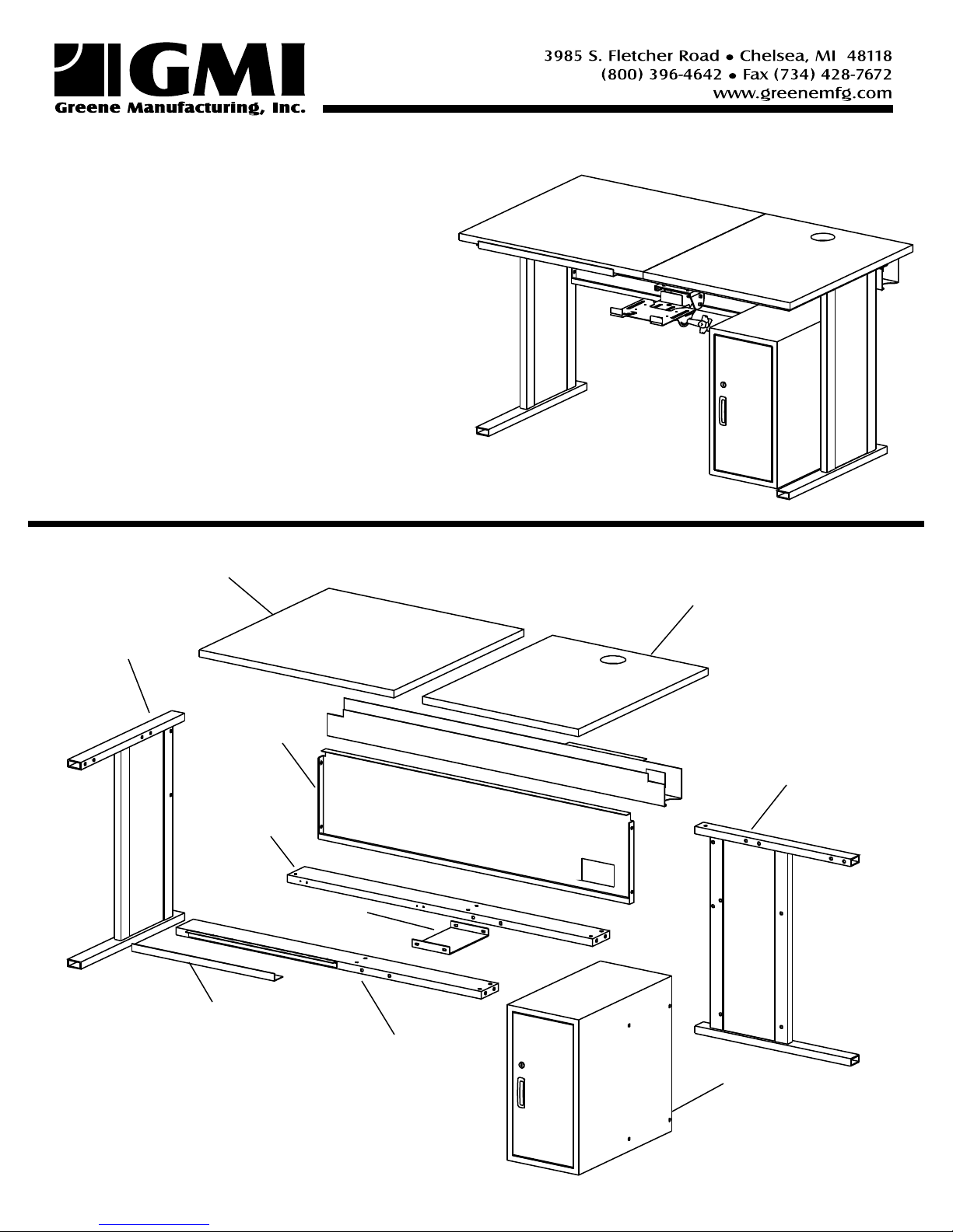
Drafting Top
Left Leg
Reference Top
Modesty Panel
Right Leg
Rear Brace
Keyboard Bracket
Pencil Edge
Front Brace
(with hinge)
CPU Cabinet
Page 2
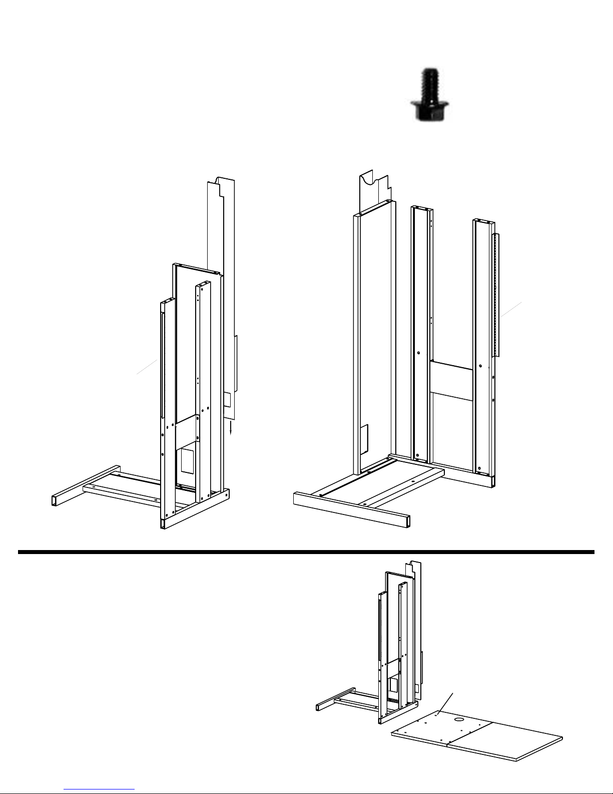
Lay RIGHT leg on the floor (see part identification on p.1).
Attach the front brace, rear brace & modesty panel to the leg.
Braces must be oriented as shown below. Use two 1/4-20 x
1/2" Flange Head Bolts for the modesty panel & two 1/4-20 x 1/2"
Flange Head Bolts for each brace.
Secure the Keyboard Mounting Bracket between the front &
STEP 1
rear brace. Use 1/4-20 x 1/2" Flange Head Bolts.
Slide the wire tray onto the top lip of the modesty panel.
Hinge
Hinge
VIEW 2
(From Top)
Set one reference & one drafting top beside the
partially assembled base as shown to the right.
Wood nut inserts facing up. Grommet hole toward
the back of the station.
STEP 2
VIEW 1
(From Bottom)
Wood Nut Insert
Side Up
Page 3

Turn the base onto the tops.
Attach the LEFT leg to the braces &
modesty panel. Use 1/4-20 x 1/2"
flange head bolts
STEP 3
Line up the front brace holes
with the holes in the reference
top. Secure with four 1/4-20 x
1/2" flange head bolts through
the braces into the top.
Verify that the drafting & reference tops are aligned.
Secure the drafting top to the front brace hinge. Use
#8 x 5/8 Black Screws.
Attach the ratchet lifts to the rear brace. Notice the orientation below. Use #8 x 5/8" black screws (2 per ratchet lift).
Attach the other end of the ratchet lifts to the drafting top using #8 x 5/8" black screws (2 per).
Remove your keyboard tray from its box. Line up the holes on the base of the tray to the holes on the keyboard mounting
bracket. Attach using four #8 x 5/8" Black screws.
STEP 4
Attach the pencil edge to the front of the drafting top (bent lip toward floor) & 1" space between the
bent lip & the edge of the drafting top. Use #8 x 5/8" Black screws
Orientation of ratchet
plate when attached to
rear brace
Hinge
Side Profile of Pencil Edge on top
Page 4

Tip the station back onto its fight side. Fasten the CPU cabinet (or
CPU rack) to the right leg using four 1/4-20 x 1/2" flange head bolts.
Turn table back into the upright position. Secure the monitor arm
to the back right-hand corner of the station.
Place grommet into large hole on reference top.
STEP 5STEP 6
If you have purchased board covers and/or straight edges, attach
them at this time. Use double sided tape to adhere the pre-cut board
covers to the drafting top. Tape should run the full length along the
top of the drafting area & ONLY along the top 1/3 of the left & right
sides
Attach straight edges according to manufacturer's instructions.
Turn the station upright. Place the filler shelf
into the bottom of the cabinet.
 Loading...