

GME Electrophone TX610 User Instructions
TX610
HANDHELD UHF TRANSCEIVER
User Instructions

2
3
Warning: Safety Information
The TX610 is a radio transmitting device.
- When transmitting, keep the antenna more
than 25mm from any part of the head or body.
- Do not transmit near electrical blasting
equipment or in explosive atmospheres.
- Do not allow children to operate a radio
transmitter unsupervised.

3
Controls. . . . . . . . . . . . . . . . . . . . . . . . . . . . . . . . . . . . . .
LCD Indicators . . . . . . . . . . . . . . . . . . . . . . . . . . . . . . . .
Powering the Transceiver . . . . . . . . . . . . . . . . . . . . . . .
General Operation . . . . . . . . . . . . . . . . . . . . . . . . . . . . .
Controls . . . . . . . . . . . . . . . . . . . . . . . . . . . . . .
Power ON/OFF Button . . . . . . . . . . . . . . . . . .
Adjusting the Volume . . . . . . . . . . . . . . . . . . .
Monitor/Backlight Button . . . . . . . . . . . . . . . .
Push To Talk (PTT) Button . . . . . . . . . . . . . . . .
Up Channel/Volume Button . . . . . . . . . . . . . . .
Down Channel/Volume Button . . . . . . . . . . . .
Mode Button . . . . . . . . . . . . . . . . . . . . . . . . . .
SIM/DUP Button . . . . . . . . . . . . . . . . . . . . . . .
Speaker/Microphone Jack . . . . . . . . . . . . . . .
Scan/Lock Button . . . . . . . . . . . . . . . . . . . . . . .
Keylock Mode . . . . . . . . . . . . . . . . . . . . . . . . .
Operating Modes . . . . . . . . . . . . . . . . . . . . . . . . . . . . . .
Mode Button . . . . . . . . . . . . . . . . . . . . . . . . . .
Channel Selection . . . . . . . . . . . . . . . . . . . . . .
CTCSS Code Selection . . . . . . . . . . . . . . . . . .
VOX Settings . . . . . . . . . . . . . . . . . . . . . . . . . .
Dual Watch Mode . . . . . . . . . . . . . . . . . . . . . .
Roger Beep Tone . . . . . . . . . . . . . . . . . . . . . . .
Button Beep Tone . . . . . . . . . . . . . . . . . . . . . .
Call Alarm Selection . . . . . . . . . . . . . . . . . . . .
Technical Specications . . . . . . . . . . . . . . . . . . . . . . . .
Channel Frequency Chart . . . . . . . . . . . . . . . . . . . . . . .
CTCSS Tone Selection Chart . . . . . . . . . . . . . . . . . . . .
Warranty . . . . . . . . . . . . . . . . . . . . . . . . . . . . . . . . . . . . .
TABLE OF CONTENTS
4
5
7
9
9
9
9
9
10
11
11
11
11
12
12
12
14
14
14
15
17
17
19
19
20
21
22
23
24
4
5
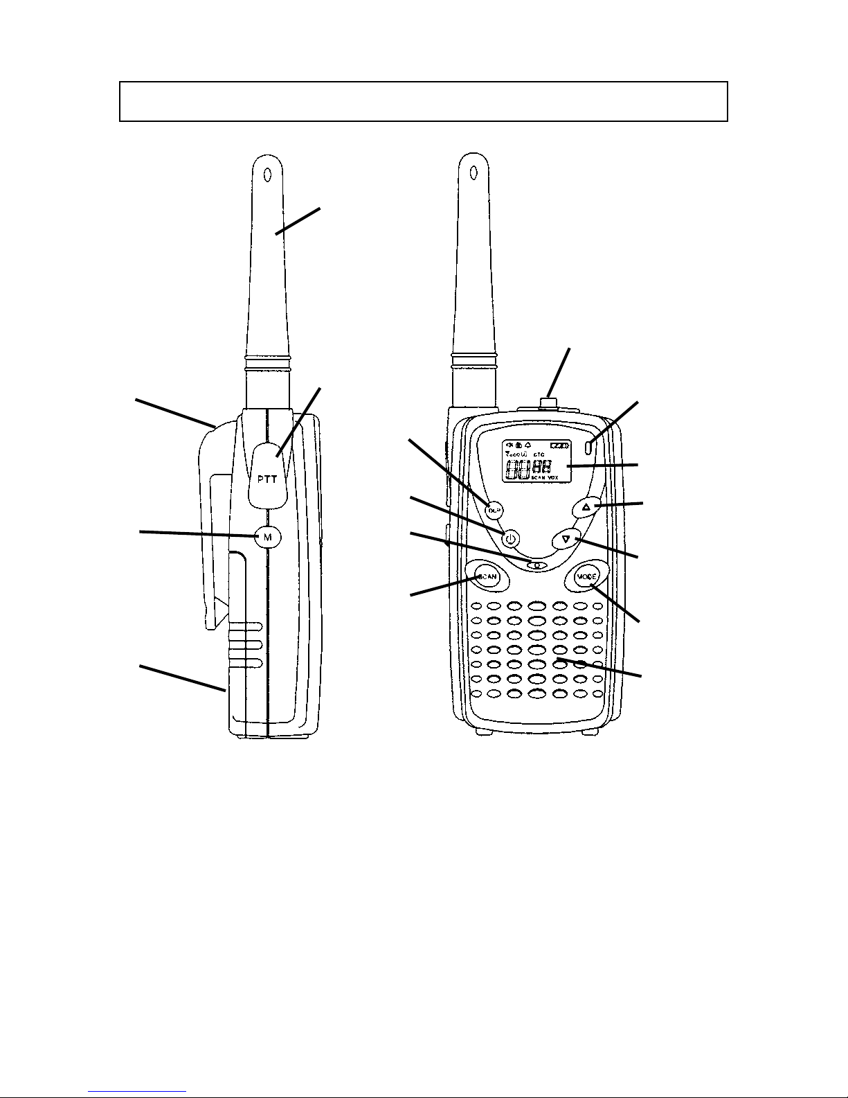
1. Battery Door.
2. Monitor/Backlight Button.
3. Detachable belt Clip.
4. Antenna.
5. Push-To-Talk Switch.
6. Scan/Key Lock Button.
7. Microphone.
8. Power On/Off.
9. Simplex/Duplex Button.
10. Socket for External
Speaker/Mic.
11. TX/RX/CTCSS Indicator.
12. Liquid Crystal Display.
13. Channel/Volume Up.
14. Channel/Volume Down.
15. Mode Button.
16. Speaker.
CONTROLS
1
2
3
4
5
9
8
7
6
10
11
12
13
14
15
16
5
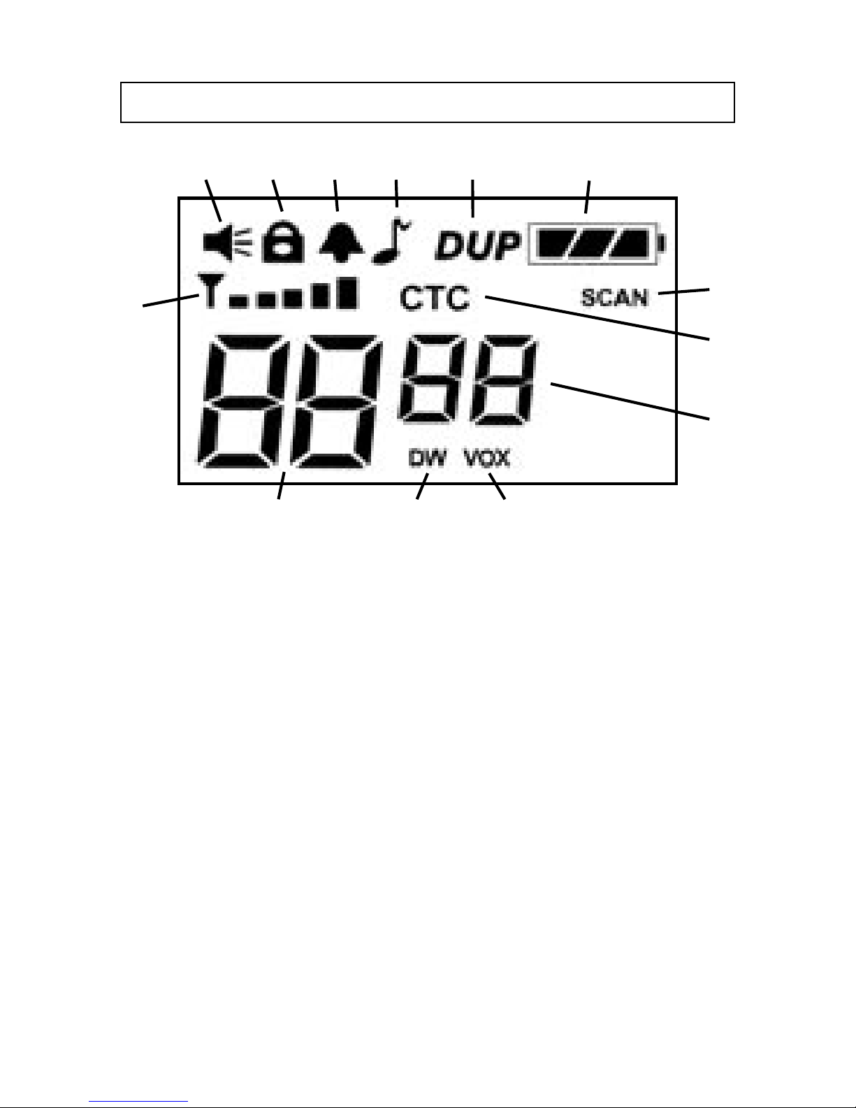
1. Signal Strength Indicator Icon: Appears when a signal
is being received. Also represents transmit signal
power during transmission.
2. Monitor Indicator Icon: Appears when the Monitor
(M) button is pressed and the channel monitor function
is activated.
3. Key Lock Indicator Icon: Appears when the keypad is
locked. This function disables keys such as channel
Up/Down and MODE.
4. Beep Tone Indicator Icon: Appears when the button
beep conrmation tone is selected. Disappears when
the button beep tone is off.
1
2 3 4 5 6 7
8
9
10
111213
LCD INDICATORS

6
7
5. Roger Beep Tone Icon: Appears when the Roger Beep
tone is on and disappears when tone is not in use.
6. Duplex Indicator Icon: Indicates that Duplex
communication has been selected.
7. Battery Level Indicator Icon: Indicates the battery
power level.
8. Scan Indicator Icon: Appears when SCAN is enabled
and the radio is scanning.
9. Continuous Tone Coded Squelch System (CTC) Icon:
Appears when the CTCSS tone function is active.
10. CTCSS Tone Display: Displays the selected CTCSS
tone (from 00-38) on the selected channel.
11. Voice Activated Transmission (VOX) Icon: Appears
when the VOX mode is activated.
12. Dual Watch Mode Icon: Appears when the Dual Watch
mode is active.
13. Channel Display: Indicates the channel number in use.
7
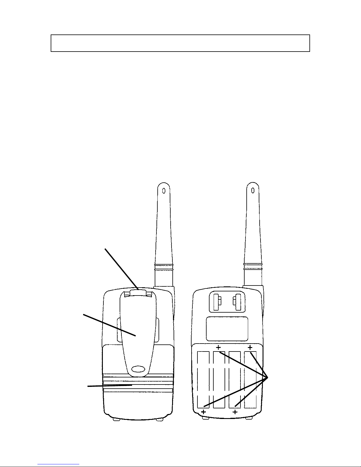
Your TX610 transceiver operates on four AAA batteries.
While you may use rechargeable batteries, alkaline batteries
will provide slightly better performance.
Installing the batteries
Battery installation is made more convenient when the belt
clip is removed. To do this, release the spring clip securing
the belt clip to the radio and slide the belt clip downward
and away from the radio body.
POWERING THE TRANSCEIVER
Spring
Clip
Belt
Clip
Battery
Cover
Positive
Terminals

8
9
To install the batteries:
1. Using your thumb, press down on the battery cover at
the arrow. Slide the cover down and lift the cover at
the bottom to open.
2. Insert four AAA batteries as shown, with alternating
positive (+) and negative (-) ends toward the bottom
beginning at the lefthand side.
Battery Power Alert
When the battery icon blinks on the display, the
battery level is low and the batteries should be replaced
(or recharged if NiCads). If the batteries are not replaced
an audio tone will sound to warn the user that the batteries
must be replaced.
The following guidelines will improve performance and
provide longer operating times for the TX610.
1. Do not mix old and new batteries.
2. The use of alkaline-type batteries is recommended
to provide the longest operating time.
3. Do not mix alkaline, standard (carbon-zinc) or
rechargeable batteries.
4. If the unit is not to be used for an extended periods
of time, remove the batteries. Old or leaking
batteries can cause damage to the unit and will
void the warranty.
 Loading...