

Page 1
INSTRUCTION MANUAL
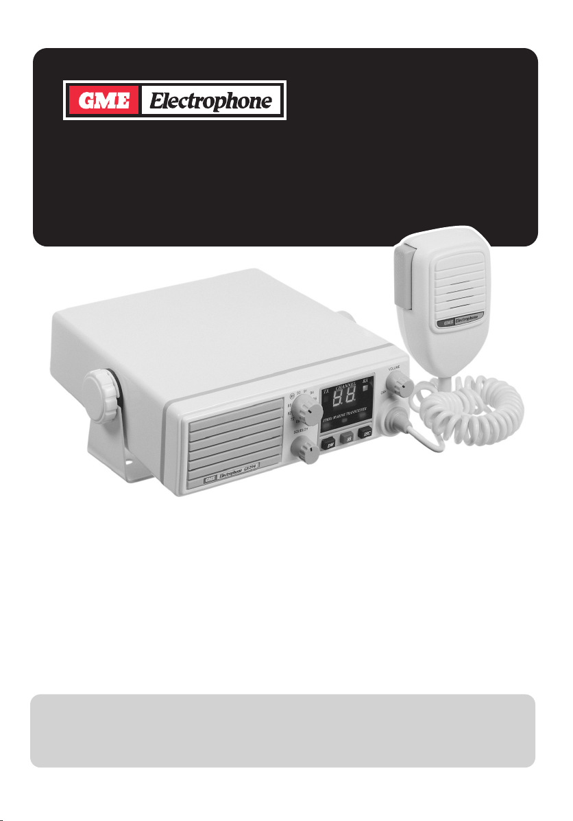
GX294
27 MHZ AM MARINE
TRANSCEIVER
Complies with Australian Standard 4367-1996
STANDARD COMMUNICATIONS
PTY. LTD.
Issue 02
Page 2

CONTENTS
Introduction . . . . . . . . . . . . . . . . . . . . . . . 3
Features . . . . . . . . . . . . . . . . . . . . . . . . . . 3
Specifications . . . . . . . . . . . . . . . . . . . . . . 4
Controls & Functions . . . . . . . . . . . . . . . . 5
Installation . . . . . . . . . . . . . . . . . . . . . . . . 7
Operating on the 27 MHz Marine Band . . 10
Accessories . . . . . . . . . . . . . . . . . . . . . . . 11
Warranty . . . . . . . . . . . . . . . . . . . . . . . . . . 12
2
Page 3

INTRODUCTION
The GME Electrophone GX294 is a high
quality 27 MHz AM marine transceiver. The
GX294 is wholly designed by Standard
Communications Pty. Ltd. in Australia, with
special attention being given to providing
protection from the harsh marine environment.
The outer case is made from non-corrosive
UV resistant A.B.S. and all case joins are fitted
with neoprene or PVC seals. A new low profile
microphone plug has been added, complete
FEATURES
■
Front mounted speaker with water
resistant mylar cone. Designed
specifically for the marine environment, the
water resistant front mounted speaker
projects the sound forward for greater
clarity and less distortion.
■
Interference Suppression Circuit.
Eliminates impulse noise caused by
electrical equipment and outboard motors
allowing only crystal clear voice signals to
be heard.
■
Dual Watch. Allows you to monitor both
the calling/distress channel (88) AND any
other selected channel.
■
Channel 88 Recall. Provides instant
selection of the calling/distress channel at
any time.
■
Electret Microphone. The Electret
microphone insert provides a higher voice
level and an improved frequency response
for crisper, clearer more natural audio.
■
Miniature microphone plug. Utilises a 6
pin telephone style plug and socket
combining superior cord grip strength with
a low profile installation.
■
Ultra bright LED display. The channel
display utilises High Intensity Light Emitting
Diode technology to produce a display
which is easy to read under a wide range
of viewing conditions.
with rubber “boot” to resist water ingress. The
high intensity LED display provides good
visibility under a wide range of viewing
conditions. In addition, the GX294 features a
Dual Watch facility, instant emergency/call
channel 88 selection and an advanced
impulse noise suppression circuit (ISC) to
provide clean, clear reception under the
noisiest electrical conditions.
■
Superior Receiver Performance. The
receiver has been specifically designed to
provide high sensitivity to weak signals and
superior noise performance with minimum
background noise.
■
Designed specifically for marine use.
The GX294 is NOT a modified CB
transceiver. It is entirely purpose designed
as a marine transceiver with a noncorrosive housing made from UV Stabilised
A.B.S. The housing features neoprene and
PVC case seals to reduce the risk of water
ingress should the radio be accidentally
splashed or exposed to light rain or spray.
In addition, the microphone plug/socket
cavity is sealed with a rubber “boot” to
minimise the possibility of corrosion and
the push buttons are part of a rubber
membrane to give total water exclusion.
■
Spare fuse holder. A unique fuse storage
bracket installed on the GX294’s rear
panel, retains two spare fuses to ensure
that you have access to the correct fuse if
you should need it.
■
Built-in Speech Processor Circuitry.
Automatically raises the average level of
your transmitted voice for greater clarity
and better penetration under poor signal
conditions.
■
Isolated earth chassis. Allows installation
in either positive or negative earth vessels.
3
Page 4

SPECIFICATIONS
GENERAL
Frequency Range:
Frequency Control:
Frequency stability:
No. of channels:
Frequencies fitted:
Antenna Impedance:
Antenna Connector:
Voltage Range:
Nominal Voltage :
Polarity:
Temperature Range:
Internal Speaker:
Extension Speaker:
Channel display:
Current Protection:
Reverse polarity and
overvoltage protection:
Dual Watch Rate:
Dimensions:
TRANSMITTER
RF Output Power:
Modulation Mode :
Modulation Sensitivity:
Frequency response :
Hum and Noise :
Modulation Distortion:
Microphone:
Current consumption:
Harmonic and spurious suppression:
27.68 MHz - 27.98 MHz
Phase locked loop
0.001%
12; 10 fitted.
27.68, 27.72, 27.82, 27.86
27.88, 27.90, 27.91, 27.94
27.96, 27.98 MHz
50 Ohm
S0-239 panel socket
10.8 - 15.2 Volts DC
12.6 Volts DC
Isolated chassis (positive or negative earth)
0° C to 55° C.
8 Ohm Mylar 2 Watt
8 Ohm with 3.5mm mono jack
High intensity Red LED
2 Amp 3AG (30mm) fuse plus internal fusible link.
Transient voltage regulator and shunt diode
2 seconds
172mm (W) x 52mm (H) x 173mm (D)
4 Watts maximum legal power
AM
60% modulation @ 1 Pascal
-12dB @ 300Hz, -16dB @ 3kHz (relative to 1kHz).
Better than -40dB
Better than 6% @ 60% modulation
Electret type
1.6 Amps @ full modulation
Better than -65dBc
RECEIVER
System:
IF Frequencies – 1st:
– 2nd:
Sensitivity :
Maximum S/N:
Selectivity :
Image Rejection:
Intermodulation:
Squelch Range:
AGC Range :
Audio Output:
Current consumption:
Spurious Emissions:
Hum and Noise:
Dual conversion superheterodyne
10.695 MHz
455 kHz
0.5uV for 12dB SINAD (0.35 uV Typical)
50dB @ 1mV input
-36dB @ ± 6kHz, -60dB @ ± 10kHz
-90dB
-60dB
Tight = 10uV, Threshhold = 0.2uV
Less than 10dB change in Audio output
over 1uV to 30mV RF input range.
3 Watts into 8 ohms (10% dist)
Full volume = 800mA,
Squelched = 350mA
-70dBm
-50dB @ 1mV RF input
4
Page 5

CONTROLS AND FUNCTIONS
■
Volume On/Off Control. Rotate the
Volume control clockwise past the click to
turn the GX294 ON. Adjust the volume
control for a comfortable listening level.
■
Squelch Control. The squelch control is
used to eliminate any annoying
background noise when there are no
signals present. To adjust the squelch,
first rotate it fully counter-clockwise until
the background noise is heard. Then
advance the squelch control clockwise
until the noise just disappears. The
receiver will now remain quiet as long as
there are no signals present, but an
incoming signal will override the squelch
and be heard in the speaker. As the
control is advanced further clockwise, the
squelch action is progressively increased
and stronger incoming signals are needed
to override it. To receive extremely weak
signals or to disable the squelch, simply
turn the control fully counter-clockwise.
■
Channel Selector. Select the required
channel by rotating the channel selector
clockwise or counter-clockwise. The
selected channel is displayed on the LED
channel display. Note that if full strength
sunlight is falling on the channel display it
may be hard to see. In this case refer to
the numbers around the channel selector
knob.
■
ISC Switch. The ISC switch activates an
extremely effective Interference
Suppression Circuit (Noise Blanker). When
selected, the ISC combines with a built in
Automatic Noise Limiter (ANL) to almost
totally eliminate electrical impulse
interference, allowing clear reception of
weak signals even under the noisiest
electrical conditions.
When the ISC switch is selected, the Red
LED indicator above it lights.
■
Channel 88 Switch. The channel 88
switch allows instant selection of the
Distress and Calling frequency 27.88 MHz.
When selected, 88 appears in the channel
display and the red Channel 88 LED above
the button lights. Pressing the 88 switch
again, returns the GX294 to the last
selected channel.
The channel 88 switch can be used to
provide instant switching between the
calling channel (88) and your local club
channel as follows:
1. Select your club channel by rotating the
channel selector switch (e.g. channel 94).
2. Press the 88 button in. Channel 88 will
be displayed and the red channel 88 LED
will light.
5
Page 6

Now, whenever you are called on channel
88 and you wish to go to your club
channel, simply press the 88 button to
release the switch. When you have
finished your conversation, press the
88 button in again to return to channel 88.
■
Dual Watch Switch. The Dual Watch
switch allows the GX294 to monitor
channel 88 AND any other selected
channel. Any signals received on channel
88 will take priority over signals on the
selected channel.
When the DW switch is first selected, the
DW indicator LED above the button lights
and the selected channel is displayed.
Then, every two seconds, the receiver
quickly switches to channel 88. If there are
no signals on channel 88, the receiver
immediately returns to the selected
channel. If a signal appears on the
selected channel, it will be heard, but the
receiver will continue to switch to channel
88 every two seconds and a brief
interruption to the signal will be noticed
each time.
■
Microphone Socket. The microphone
attachment on the GX294 is a unique
arrangement which utilises a 6 pin
telephone style plug and socket. This
provides superior cord grip strength and a
low profile installation. The cord entry is
then sealed against moisture by a rubber
grommet.
■
LED Channel Display. The LED channel
display shows the currently selected
channel.
■
Transmitting. To transmit, press the PTT
button on the microphone. Hold the
microphone 2-6 cm from your mouth and
slightly to one side, so that your voice does
not project directly into the microphone.
Speak at a normal voice level.
The GX294 has a built-in speech processor
circuit which automatically controls the
average level of your transmitted voice for
greater clarity and better “penetration”
under poor signal conditions. It is not
necessary to raise your voice or shout into
the microphone.
If any signal is found on channel 88, the
receiver will stop switching and will remain
on channel 88 for as long as the signal is
present. During this period the red channel
88 indicator LED will flash. When the
signal has gone, the receiver will begin
Dual Watching again.
Pressing the Push-to-talk button on the
microphone causes the GX294 to transmit
on the selected channel.
■
RX Indicator. A green LED which lights
while the GX294 is in the receiver mode
and extinguishes in the transmit mode.
■
TX Indicator. A red LED which lights only
when transmitting.
■
DW Indicator. A red LED which lights
when the Dual Watch function is selected.
■
Channel 88 Indicator. A red LED which
lights when the 88 switch is selected. It
also lights and flashes when channel 88 is
active in the Dual watch mode.
■
ISC Indicator. A red LED which lights when
the ISC function is selected.
Microphone
PTT Switch
6
Page 7

INSTALLATION
It is advisable to spend a little time selecting
the best location for your GX294. The
transceiver should normally be mounted
horizontally, but may be mounted vertically if
desired. The bracket supplied can be fitted
above or below the case allowing the GX294
to be cradled by the bracket or suspended
from it. Alternatively, the GX294 can be flush
mounted to a panel or bulkhead.
When choosing a suitable location, consider
the following points:
1. Install the GX294 in a sheltered position.
The design of the GX294 provides
protection against accidental splashes and
drips, but the equipment is not totally
waterproof. Exposure to heavy rain,
continuous spray or immersion will result in
damage to the transceiver.
2. Avoid exposure to direct sunlight for
prolonged periods which could cause
overheating.
3. Choose a spot where the microphone and
all controls are easily accessible and the
loudspeaker can be heard from the normal
steering position. An extension speaker
may be installed if required.
4. Components and currents flowing in the
GX294 create magnetic fields. To avoid
interference to steering compasses or auto
pilot sensors, the GX294 should be
positioned at least half a meter (50cm) from
such equipment.
the radio to the bracket by means of the
thumb screws. Remember that the fixings for
overhead mounting may have to withstand
heavy pounding when the vessel is in rough
water or being towed on a trailer.
Flush Mounting
Using the MK200W flush mounting kit:
If using the optional MK200W flush mounting
kit, simply follow the instructions provided
with the kit. The fully self supporting design of
the MK200W greatly simplifies installation and
provides a professional finish.
MK200W Flush
Mounting Kit
MOUNTING
Your GX294 can be either mounted on a shelf
or flush mounted into a bulkhead or panel. If
flush mounting the GX294 we recommend you
use the optional MK200W flush mounting kit
available from your GME branch or dealer.
This will help give a professional appearance
to your installation.
Shelf Mounting
Attach the bracket above or below the shelf
as desired using the screws provided. Secure
Using the standard mounting bracket:
If flush mounting the GX294 using the
standard mounting bracket, we recommend
the following procedure:
1. Cut a slot in the bulkhead or panel 172mm
wide x 52mm high. The corners of the slot
should be rounded to fit neatly with the
shape of the GX294’s case.
7
Page 8

2. If not already fitted, install a small shelf
SPK09
behind the bulkhead to take the mounting
bracket. Slide the GX294 through the slot
from the front and fit the mounting bracket
to the shelf from behind the bulkhead.
Adjust the assembly so the radio protrudes
through the slot as required and screw the
bracket into that position. Mount the
microphone holder in a convenient position
near the transceiver. Avoid fouling other
equipment with the microphone cord.
Power Connections
The GX294 can be installed in vessels with
either positive or negative ground electrical
systems. The radio’s positive (RED) lead must
be connected to the positive (+) side of the
electrical system and the negative (BLACK)
lead must connect to the negative (-) side.
Reversal of these connections will cause the
fuse to blow and may seriously damage the
transceiver and void the warranty.
If the fuse blows at any time, FIT ONLY THE
CORRECT 2 AMP 3AG (30mm) type. Two
spare fuses are clamped to the GX294’s rear
panel.
If the power leads are not long enough they
can be extended using at least 4mm outside
diameter cable.
8
Page 9

DISCONNECTING THE
MICROPHONE
It is recommended that the microphone be left
permanently connected to the GX294, but if it
must be disconnected proceed as follows:-
3. Identify the plug locking lever, work the
screwdriver blade behind it and move the
lever towards the plug body, at the same
time gently pull the plug from the socket.
( See diagram below )
1. Insert a small screwdriver between the
rubber boot and lip of the raised area on
the front panel.
2. Ease the rubber boot out of the cable entry
hole and slide it along the cable away from
the front panel.
ANTENNA INSTALLATION
NEVER TRANSMIT WITHOUT AN
ANTENNA CONNECTED
OTHERWISE DAMAGE MAY
RESULT TO THE TRANSCEIVER.
If required, replacement microphones are
available with plug and rubber boot already
fitted.
All GME antennas are pretuned thereby
eliminating the need for ground planes and
tuning units. You do not even need to be
concerned with the construction of your craft.
All GME antennas are suitable for aluminium,
fibreglass, ferro cement or timber
construction.
It is essential to select a good quality high
efficiency 27 MHz marine antenna. A poor
quality antenna or one not designed for the 27
MHz marine band will give very poor
performance and could cause damage to the
transceiver. Standard 27 MHz CB antennas
are NOT suitable.
GME manufacture a wide range of antennas
suitable for every application. These include
small antennas for runabouts, swivel bases for
various mounting positions, larger antennas
for cruisers and even antennas designed
specifically for yachts.
When installing the antenna, make sure that it
is well clear of any metal rails or rigging, as
these will detune it and reduce performance.
The cable should be fed through a small hole
in the cabin or deck. The rubber grommet
supplied provides a tidy fit and can be sealed
with silastic. The PL259 type antenna plug
should be screwed to the antenna jack on the
rear of the GX294. DO NOT CUT THE COAX
CABLE. If the supplied cable is too long, coil
it up out of the way. Shortening the cable will
adversely affect the antenna’s tuning.
9
Page 10

OPERATING ON THE 27MHZ MARINE BAND
Normal Operating Procedure
Most calls to other vessel or stations are
made on channel 88. After listening to ensure
channel 88 is clear, call the other station,
repeating both call signs three times.
e.g.“Coast Guard, Coast Guard,Coast Guard,
This is –
Seaspray, Seaspray, Seaspray,
Over.”
Once contact has been established, move
straight to another channel (e.g. 91 or 94) to
continue your conversation leaving channel 88
clear for emergencies or further calls. Don’t
forget to return to channel 88 or select dual
watch when you have finished otherwise you
may miss other calls meant for you.
Emergency Procedures
All emergency calls should be made on
channel 88. There are three main types of
Emergency call.
1. “MAYDAY, MAYDAY, MAYDAY”
This call should be used where you are in
grave and imminent danger and require
MARINE CHANNEL ASSIGNMENTS
immediate assistance. You should call
MAYDAY three times followed by your vessels
name or callsign three times. Then state your
position, a brief description of your vessel, the
nature of the emergency, the number of
people on board and their condition. If you
hear no reply, repeat the call at short intervals
because someone may be able to hear you
but you might not be able to receive their
reply.
After contact has been made, follow any
instructions given to you.
2. “PAN PAN, PAN PAN, PAN PAN”
Use this call when an emergency situation
exists but there is no immediate danger. The
call should be made the same way as the
MAYDAY call. If you hear no reply repeat the
call at regular intervals.
3. “SECURITE, SECURITE, SECURITE”
(Pronounced Say-cure-e-tay).
This call is used to warn other shipping of
dangers or hazards e.g. bad weather,
container adrift etc. The call may be made to a
local monitoring station or to all ships in the
area.
CHANNEL FREQUENCY USE
68 27.680 MHz Commercial, ship-shore-ship
72 27.720 MHz Professional fishing
82 27.820 MHz Professional fishing
86 27.860 MHz Secondary distress and safety
88 27.880 MHz Primary distress and calling only
90 27.900 MHz Domestic ship-shore-ship
91 27.910 MHz Domestic ship-shore-ship
94 27.940 MHz Club events, ship-shore-ship
96 27.960 MHz Ship to ship
98 27.980 MHz Rescue organisations
10
Page 11

GME ELECTROPHONE APPROVED ACCESSORIES
SPK09
G
X
5
48
CH 16
Auto Seaphone
DN
27 MHz MARINE ANTENNAS
AE60 - 1.8 Mtr Pretuned Antenna - white.
Comes with lead & plug.
AE60B - 1.8 Mtr Pretuned Antenna – black
whip for ultra violet protection.
Comes with lead and plug.
AE61BY - 1.8 Mtr Pretuned Yacht Antenna.
AE96 - 2.5 Mtr Pretuned Antenna
with two-way swivel base.
Comes with lead & plug.
AE229 - 1/2 Wave Aluminium 26 – 28 MHz
Base Antenna.
ACCESSORIES
PSA123 - 2 Amp continuous Power Supply.
AE60
AE96 AE61BY AE229
SPK04 - 4 Ohm extension speaker with
flush mounting plug & 1.7 meter lead.
SPK09 - 4 Ohm Box type extension
speaker with lead and plug.
MK200W - Flush Mounting Kit.
OTHER QUALITY GME ELECTROPHONE PRODUCTS
GX558A - 54 Channel
VHF Transceiver with fist
microphone LCD display
and built-in Seaphone.
GX548 - 54 Channel
VHF Transceiver with fist
microphone and LED display.
GX292 - 27 Mhz AM
Handheld Transceiver.
GX560 - Handheld 54
Channel VHF Transceiver,
3 Watt/ 1 Watt output.
SPK04
PSA123
SPK09
MK200W
GX560
GX558A
GX292
GX548
11
Page 12

WARRANTY
GME ELECTROPHONE limit this warranty to
the original purchaser of the equipment.
connection to an antenna which has been
incorrectly installed, resulting in damage
to the transceiver’s output transistors.
GME ELECTROPHONE warrant this product
to be free from defects in material and
(d) Effects of water or moisture penetration.
workmanship for a period of twelve (12)
months from the date of purchase from their
(e) Non-factory modifications.
authorised dealer.
(f) Use of incorrect replacement fuse.
Should the product require servicing during
this period, all labour and parts used to effect
repairs will be supplied free of charge. GME
ELECTROPHONE reserve the right to
determine whether damage has been
occasioned by accident, misuse or improper
installation whereby the warranty would be
void, including:
Procedure followed by claimant:-
In the event of a defect occurring during the
twelve (12) month warranty period, the original
purchaser may return the defective unit along
with suitable proof of purchase date
(i.e. receipt, docket, credit card slip etc.) and a
full description of the defect to the Dealer
from whom the unit was purchased.
Transceivers which have been damaged due
to:
All freight charges incurred for transportation
by the Dealer or GME ELECTROPHONE are
(a) Incorrect or reverse polarity connection to
the purchaser’s responsibility.
a battery or power supply.
The Dealer may be able to repair the defect or
(b) Connection to incorrect supply voltage.
may forward unit to the closest authorised
GME ELECTROPHONE Service Depot in
(c) Operation without an antenna or by
your particular State.
GME ELECTROPHONE AFTER SALES SERVICE
Your ELECTROPHONE transceiver is especially designed for the environment encountered in
marine installations. The use of all solid state circuitry, careful design and rigorous testing, result
in high reliability. Should failure occur however, GME ELECTROPHONE maintain a fully
equipped service facility and spare parts stock to meet the customer’s requirements long after
expiry of the warranty period.
MELBOURNE
96 Voltri Street,
MENTONE 3194
(03) 9584 8099
Fax : (03) 9584 8446
A Division of
BRISBANE
Unit 1, 89-101 Factory Rd,
OXLEY 4075
(07) 3278 6444
Fax : (07) 3278 6555
STANDARD COMMUNICATIONS PTY. LTD.
Head Office: SYDNEY
6 Frank Street, GLADESVILLE 2111
Ph: (02) 9844 6666 Fax: (02) 9844 6600
ADELAIDE
Unit 1/4 West Thebarton Rd,
THEBARTON 5031
(08) 8234 2633
Fax : (08) 8234 5138
PERTH
Unit 4, 43 Norma Rd,
MYAREE 6154
(08) 9330 5322
Fax : (08) 9317 1787
12
AUCKLAND
P.O. Box 58446
GREENMOUNT
(09) 274 0955
Fax : (09) 274 0959
 Loading...