

Page 1

GR100
AM/FM/VHF
MARINE
BROADCAST
RADIO
INSTRUCTION MANUAL
Page 2

Page 2 Instruction Manual GR100
CONTENTS
FEATURES ........................................................ 3
ACCESSORIES ..................................................... 3
COMPLIANCE ..................................................... 4
LISTENING TO FM IN YOUR BOAT . . . . . . . . . . . . . . . . . . . . . . . . . . . . . . . . . . . . . . 4
LCD DISPLAY ...................................................... 4
CONTROLS . . . . . . . . . . . . . . . . . . . . . . . . . . . . . . . . . . . . . . . . . . . . . . . . . . . . . . . 5
Power Key . . . . . . . . . . . . . . . . . . . . . . . . . . . . . . . . . . . . . . . . . . . . . . . . . . . . 5
Mode Key . . . . . . . . . . . . . . . . . . . . . . . . . . . . . . . . . . . . . . . . . . . . . . . . . . . . 5
Band Key ..................................................... 5
Up/Down Keys ................................................. 6
Memory Keys .................................................. 6
OPERATION . . . . . . . . . . . . . . . . . . . . . . . . . . . . . . . . . . . . . . . . . . . . . . . . . . . . . . 6
Turning the GR100 ON and OFF .................................... 6
Adjusting the Sound. . . . . . . . . . . . . . . . . . . . . . . . . . . . . . . . . . . . . . . . . . . . . 6
Tuning for Stations .............................................. 8
Memory Keys .................................................. 9
Automatic Memory Storage . . . . . . . . . . . . . . . . . . . . . . . . . . . . . . . . . . . . . . . 9
Local/DX Mode . . . . . . . . . . . . . . . . . . . . . . . . . . . . . . . . . . . . . . . . . . . . . . . 10
Stereo/Mono Mode . . . . . . . . . . . . . . . . . . . . . . . . . . . . . . . . . . . . . . . . . . . . 10
INSTALLATION . . . . . . . . . . . . . . . . . . . . . . . . . . . . . . . . . . . . . . . . . . . . . . . . . . . 10
Mounting the GR100 ........................................... 11
Electrical Wiring ............................................... 12
SPECIFICATIONS .................................................. 14
STANDARD COMMUNICATIONS CONTRACT WARRANTY. . . . . . . . . . . . . . . . . . . . 15
BRANCH ADDRESSES . . . . . . . . . . . . . . . . . . . . . . . . . . . . . . . . . . . . . . . BACK PAGE
Page 3

Page 3GR100 Instruction Manual
FEATURES
Compact design with bracket or flush mounting options
•
Ingress Protection to IP55*
•
7 Bands (LW, SW, AM1, AM2, FM1, FM2, VHF)
•
6 Preset Frequency memories per band
•
Simple Push button Controls.
•
Front panel ‘monitor’ speaker
•
Large amber backlit display with ‘Dim’ feature
•
FM stereo reception
•
Bass, treble and balance controls
•
Separate bass and treble memories for each band
•
Over voltage indicator
•
Reverse polarity protection
•
Static discharge protection at antenna input
•
User selectable VHF frequencies & NOAA Weather channels
•
Available in black or white
•
ACCESSORiES
Supplied
2 x Extension speaker leads - 3.5 mm mini jack
Mounting bracket, gimbal knobs and Stainless Steel screws
DC supply lead
Instruction manual
Optional
In-dash flush mounting kits – MK100W (white), MK100B (black), MK002W, MK002B.
Rear flush mount kit – MK600
Choose from a range of GME antennas
Choose from a range of GME speakers
Cabin cover – CVR001 (white), CVR001B (black).
*Refer: www.gme.net.au/IPRatings/IPRatings.html
Page 4
Page 4 Instruction Manual GR100
COMPLiANCE
This device complies with AS/NZS 1053-CISPR13
This device complies with part 15 of the FCC rules. Operation is subject to the
condition that this device does not cause harmful interference.
LiSTENiNG TO FM iN YOUR BOAT
The majority of FM broadcasts are music programs. Compared with AM signals, FM
signals have a wider dynamic range, are relatively immune to noise and provide
virtually distortion free music reproduction. However, because of the nature of FM
signals and the fact that FM stations are usually positioned for shore based reception,
reception in a moving boat may be accompanied by problems.
FM programs are broadcast for local reception and may not be heard satisfactorily at
distant locations. To enjoy FM programs at their best, it is important that you tune to a
station that is broadcasting in your locality.
FM signals can reflect from solid objects such as buildings or hills. If these reflected
signals are received along with signals that are arriving directly from the transmitter,
they may mix together to produce what is known as ‘multipath distortion’. This
distortion is heard as noise. Often, moving as little as one metre from your position will
correct this problem.
FM signals travel in straight lines. Because the signals are reflected from or absorbed
by large solid objects, a signal ‘shadow’ may be present behind the object which may
result in poor reception in that area.
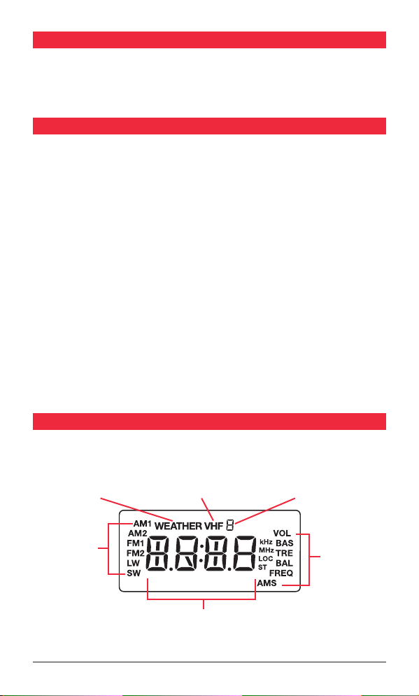
LCD DiSPLAY
Weather Channels
Band Selection
VHF Channels Memory number
Modes
Frequency
Page 5
Page 5GR100 Instruction Manual
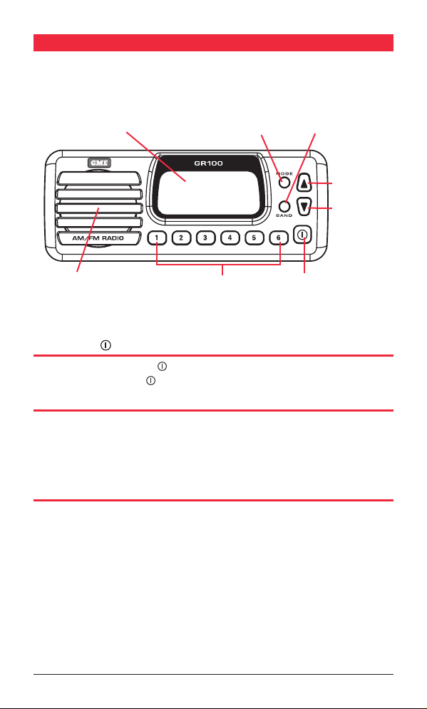
CONTROLS
LCD Display Mode Key
M
B
Band Key
Up Key
Down Key
Speaker
Memory Keys Power/Mute Key
POWER KEY
Press and hold the Power key to turn the GR100 ON or OFF. While the radio is ON,
briefly press the Power key to toggle the audio mute button.
MODE KEY (M)
The Mode Key provides access to the Volume, Bass, Treble, Balance, Frequency
Adjustment, Automatic Memory Store (AMS) and Local/DX settings.
The Mode selection will automatically return to the Volume setting 20 seconds after
the last key press.
BAND KEY (B)
The GR100 has 7 selectable frequency bands labelled LW, SW, AM1, AM2, FM1, FM2
and VHF. Each press of the BAND key cycles to the next band in sequence and a
corresponding icon (LW, SW, AM1, AM2, FM1, FM2 or VHF) is displayed.
The frequency coverage for each band is listed in the specifications at the rear of
this manual.
Page 6

Page 6 Instruction Manual GR100
UP/DOWN KEYS
The Up and Down keys are used to adjust functions selected using the Mode key.
MEMORY KEYS
Six memory keys are provided for storage and retrieval of station memories.
OPERATiON
TURNING THE GR100 ON & OFF
To switch the GR100 on, press and hold the key for two seconds.
The radio will turn ON.
To switch the GR100 off, press and hold the
The radio will turn OFF.
Note: When the GR100 is switched off or the power is interrupted, it will remember
the last state that it was set to and return to that state when it is switched back on.
key for two seconds.
ADJUSTING THE SOUND
Adjusting the Volume.
During normal use, the GR100 will default to the Volume mode. Whenever the Volume
mode is selected ‘VOL’ is displayed on the right of the LCD. If you are not in the
Volume mode, briefly press the Mode key repeatedly until ‘VOL’ is displayed on
the LCD.
To adjust the Volume, press the
Volume while pressing the key will decrease the Volume. The volume setting will be
displayed on the LCD. Minimum Volume setting displays a value of 0 with a maximum
volume setting of 33. To quickly adjust the Volume setting, press and hold the
or key.
or key. Pressing the key will increase the
Adjusting the Bass
To select the bass mode, briefly press the Mode key repeatedly until BASS is displayed
on the right of the LCD. To adjust the bass, press the or key. Pressing the
key will increase the bass while pressing the Key will decrease the bass. The bass
setting will be displayed on the LCD. Minimum bass setting displays a value of -7 with
a maximum bass setting of +7. A setting of 0 indicates a flat bass response. To quickly
adjust the bass setting, press and hold the or key.
Adjusting the Treble
To select the treble mode, briefly press the Mode key repeatedly until ‘TRE’ is displayed
on the right of the LCD. To adjust the treble, press the or key. Pressing the key
Page 7

Page 7GR100 Instruction Manual
will increase the treble while pressing the key will decrease the treble. The treble
setting will be displayed on the LCD. Minimum treble setting displays a value of -7
with a maximum treble setting of +7. A setting of 0 indicates a flat treble response. To
quickly adjust the treble setting, press and hold the or key.
Adjusting the Balance
The balance setting controls the audio balance between the left and right speaker.
Note: The balance mode is only available when the external speakers are attached. If
running the GR100 from the internal monitor speaker, the balance function is skipped
when the Mode key is pressed.
Briefly press the Mode key repeatedly until ‘BAL’ is displayed on the right of the
LCD. To adjust the Balance, press the
balance towards the left speaker while pressing the Key will adjust the Balance
towards the right speaker. The Balance setting will be displayed on the LCD. Full left
balance displays a value of L10 with a full right balance setting of R10. A setting of
0 indicates the balance is set equally between both speakers. To quickly adjust the
Balance setting, press and hold the or key.
or key. Pressing the key will adjust the
Muting the Sound
The Mute feature allows the radio’s sound to be temporarily disabled without affecting
any other settings. This could be useful when making calls on your two way radio or
mobile phone or during a local conversation where the radio sound is distracting.
To temporarily mute the radio, briefly press the
disabled and no sound will be heard from the speaker(s). While the sound is muted,
‘MUTE’ will flash on the display.
To cancel the Mute selection and restore the sound to its previous level, briefly press
key again.
the
key. The audio will be temporarily
Dimming the Display
The display lighting can be dimmed for night time viewing. The default setting is
maximum brightness. To dim the display:
1. Press and hold the
2. Now press and hold the
THE KEY YET.
3. Now briefly press the M key to toggle the display lighting dim or bright. Once you
have selected the display lighting you can release the
key to turn the GR100 OFF.
key again. The GR100 will turn on. DON’T RELEASE
key.
Page 8

Page 8 Instruction Manual GR100
TUNING FOR STATIONS
Selecting the Frequency Band
The GR100 has 7 selectable frequency bands labelled LW, SW, AM1, AM2, FM1, FM2
and VHF. The two AM bands (AM1 and AM2) are identical to each other as are the two
FM bands (FM1 and FM2).
To select the required frequency band, briefly press the Band key. Each press will
advance to the next band in sequence and a corresponding icon (LW1, SW, AM1, AM2,
FM1, FM2 or VHF) will be displayed.
Selecting USA or European Receiver Standards
The GR100 supports both USA and European standards for AM and FM reception.
Australian models conform to the European standard and are set that way by default.
Owners in the USA should select the USA standard.
To toggle between European or USA standards, press and hold the Band key for 3
seconds. The GR100 will display ‘E’ at the top of the display for European or U for USA.
The E or U will disappear when any of the preset memory buttons are pressed.
The differences between European and USA bands and their frequency steps are listed
in the specifications at the rear of this manual.
Note: When the VHF marine band is selected, switching between USA and European
standards will also select USA or International VHF marine channel allocations.
Manually Tuning the Frequency
Briefly press the Mode key repeatedly until ‘FREQ’ is displayed on the right hand side
of the LCD. You can now manually change the frequency. To adjust the frequency,
briefly press the or key. Pressing the key will increase the frequency while
pressing the Key will decrease the frequency. The frequency will be displayed on the
LCD.
Scanning for Stations
While in frequency tuning mode, press and hold the or key for 3 seconds. The
GR100 will automatically scan upwards or downwards in frequency starting at the
present frequency. When a station is found, scanning will stop on that frequency.
Note: When tuning in the VHF band, standard VHF marine channel numbers 1-28 and
60-88 are displayed. If the USA standard is selected, an additional ten NOAA weather
channels are also available. When these are selected, ‘WEATHER’ is displayed on
the LCD.
Page 9

Page 9GR100 Instruction Manual
MEMORY KEYS
The GR100 has 6 preset memory keys which allow up to 6 frequencies to be stored
and recalled within each band. Because there are two identical AM bands and two
identical FM bands, this allows 12 AM and 12 FM preset memories. The memories can
be stored either manually or automatically.
Manually locating and storing station frequencies in the preset Memories
1. Press the Band key repeatedly until the required band is selected.
2. Press the Mode key repeatedly until the frequency adjustment mode is selected
(‘FREQ’ will be displayed).
3. Press the
automatically scan for the next station, press and hold the or key.
4. Once the required station has been located, press and hold one of the six memory
keys for 3 seconds. The frequency will flash and the sound will mute briefly as the
frequency is stored into the selected memory. The selected memory number will be
displayed at the top of the LCD.
Repeat steps 3 and 4 above to store other frequencies into the preset memories.
Note: If a frequency or VHF marine channel is selected that is already stored in
memory, the allocated memory number will also be displayed.
or key briefly to manually step through the frequencies. To
Recalling stations from the preset Memories
Select the required band, then briefly press the required memory button. The GR100
will switch to the frequency stored in that memory location and the selected memory
number will be displayed at the top of the LCD.
AUTOMATIC MEMORY STORAGE (AMS)
The AMS feature allows the GR100 to search the selected band for stations and
automatically store the first six strongest stations it locates into the station memories.
While activated, the Local (LOC) receiver sensitivity mode is temporarily selected to
ensure only stronger local stations are selected.
To activate the AMS feature, briefly press the Mode key repeatedly until ‘AMS’ is
displayed on the lower right of the LCD. To begin the search, press the
Pressing the key will cause the GR100 to search upwards through the frequencies
while pressing the key will cause it to search downwards. The search will begin from
the last displayed frequency. As strong stations are found they will be automatically
stored into the station memories. When all six memories have been filled, or the entire
band has been searched, the search will stop and the station in Memory 1 is selected.
To manually stop the memory search, briefly press the
search direction, briefly press the opposite key after the search has been
manually stopped.
or key. To change the
or key.
Page 10

Page 10 Instruction Manual GR100
LOCAL/DX MODE
The Local/DX mode controls the receiver’s sensitivity when in the FM mode. The GR100
can be set to high sensitivity for long distance reception (DX) or low sensitivity for local
reception (LOC).
Briefly press the Mode key six times (one press past the AMS selection). The frequency
will be displayed along with the LOC symbol. To select Local or DX modes, briefly press
or key. Each press will alternate between a solid LOC symbol (indicating Local
the
mode is selected) and a flashing ‘LOC’ symbol (indicating DX mode is selected).
When the GR100 returns to the normal display mode, a ‘LOC’ icon on the display
indicates that local mode is selected. If ‘LOC’ is not visible, DX mode is selected.
STEREO/MONO MODE
The Stereo/Mono function can be selected on the FM band when the external stereo
speakers are attached. If the GR100 is only operating from the internal monitor
speaker, Mono/Stereo selection is not available.
Mono
Selecting Mono improves the quality of the reception when FM signals are weak or
noisy by disabling stereo detection. When Mono is selected, there is no indication on
the display
Stereo
Select stereo for normal stereo listening on the FM bands. When stereo is selected and
a stereo signal is being received, ‘ST’ is displayed.
To switch between Mono and Stereo modes, press and hold the Mode key for 3
seconds. The ST icon will appear or disappear indicating the current selection.
iNSTALLATiON
Rear Panel Connections
Antenna Socket
DC Power
Left Speaker Output
Right Speaker Output
Page 11

Page 11GR100 Instruction Manual
MOUNTING THE GR100
The GR100 is designed to be mounted in several different ways to enable it to be
installed in the most convenient position. The GR100 is designed to meet IP55
Standard (Refer: www.gme.net.au/IPRatings/IPRatings.html). A location should be selected
which provides the best viewing angle for the display. For best results select a location
that is free from excessive vibration and continuous direct sunlight.
Panel Mount Overhead Mount Upright Mount
Upright or Overhead Mounting.
Position the mounting bracket onto the GR100 so that the mounting holes in the
bracket align with those on the side of the unit, and fit the gimbal knobs. Temporarily
position the bracket in the desired location and roughly mark the bracket edges. Now
remove the unit from the bracket and reposition the bracket to mark the mounting
holes. Screw or bolt the bracket into position. The mounting method will depend on
the surface to which the bracket is being attached. Refit the GR100 to the bracket and
adjust the unit to the correct position before tightening the gimbal knobs.
Complete the antenna lead and electrical wiring as described later.
Flush Mounting
If you require to flush mount your GR100 we recommend the MK100 flush mounting
kit designed especially for the purpose. Instructions and a mounting template are
included with the kit.
Panel
Bracket
GR100
Page 12

Page 12 Instruction Manual GR100
ELECTRICAL WIRING.
The GR100 is suitable for either negative or positive ground systems.
Note: The GR100 has an over voltage detector to indicate when excessive voltage is
being applied to the radio. The over voltage detector is triggered when the voltage
being applied to the power leads exceeds 18 Volts DC. If this happens, the words
‘hi dc’ will flash on the display. If the voltage exceeds 21 Volts DC, the radio will
automatically shut down.
Referring to the wiring diagram
1. Connect the RED fused wire directly to the positive terminal of the battery or to a
point in the vessels electrical wiring that provides a +12 Volt connection.
2. Connect the Black negative wire directly to the battery’s negative terminal or to a
negative point in the vessels wiring.
Speaker Connections
Note: For simple installations, the GR100 can be used without external speakers if
required. The GR100’s internal monitor speaker can provide good quality mono sound
suitable for many applications. For full stereo sound you will need to connect a pair of
external speakers. The GR100’s internal monitor speaker is automatically disconnected
when the external speakers are plugged in.
Page 13

Page 13GR100 Instruction Manual
The GR100 is supplied with two speaker adapter leads which are designed to accept
the standard bullet connectors found on some GME marine speakers and most marine
and automotive speaker cables. The plugs on the speaker adapters plug into the
matching the sockets on the rear of the GR100. The plugs are fitted with protective
flexible covers.
When connecting the speakers, observe the correct polarity as shown in the diagram.
Incorrect polarity will result in a reduction of bass response and stereo effect. The use
of speakers with an impedance of less than 4 ohms is not recommended as they will
cause excessive loading of the GR100’s output circuit.
The GR100 is a two speaker system that requires one pair of wires for each speaker.
Avoid shorting the speaker wires together or touching them to the supply voltage or
to ground.
Once the GR100 is connected, you can adjust the balance between the left and right
speaker using the Balance function.
Antenna Connection
The antenna should be mounted in a position as high as practical to ensure good
reception especially in areas of low signal strength. When installing the antenna,
ensure a minimum clearance of around 20 cm from bow or stern rails or windscreen
frames etc. It is also recommended the antenna be placed at least one metre from
two-way radio antennas to minimise interference from radio transmissions.
To connect the antenna to your GR100, simply plug the antenna lead into the flying
antenna socket on the rear of the unit.
Waterproofing the connections
After installation, the power, speaker and antenna connectors should be wrapped in
waterproof tape or similar to minimise the risk of corrosion or water damage. Do not
use normal electrical tape as this will not provide an adequate seal against water.
The connectors should then be positioned where they are not directly exposed to the
elements.
Fuse Replacement
If the fuse in the DC lead should blow, it should be replaced with a 2 Amp 3AG type.
In the event of a failure, the use of a higher value fuse could result in damage to your
GR100 which would void the warranty.
Page 14

Page 14 Instruction Manual GR100
SPECiFiCATiONS*
GENERAL
Complies with: AS
Frequency Range: LW, MW, SW, VHF, AM and FM
Channel Set: Broadcast Radio Bands
Scan Speed: 100 ms/channel
Supply Voltage Range: 10.8–15.6 V DC negative earth
Current Protection: 2 A 3 AG fuse
Reverse Polarity &
Over Voltage Protection: ‘hi dc’ at 18 V shutdown at 21 V
RECEIVER
IF Frequencies: 1st: 10.7 MHz, 2nd: 450 kHz
Modulation Frequency Response: 60 Hz–15 kHz for FM
Adjacent Channel Rejection: > 73 dB
Intermodulation Rejection: > 73 dB
Blocking Rejection: > 90 dB
Spurious Rejection: > 75 dB
Audio Output Power: 4 Watts x 2 average into external 4 Ohms
Audio S/N: > 45 dB
Conducted Spurious Emission: < -70 dB
Current Consumption: Full Volume: 1.2 A
SENSITIVITY
AM: -101 dBm 20 dB SINAD
FM: -101 dBm 30 dB SINAD
VHF: -105 dBm 12 dB SINAD
MECHANICAL
Unit Dimensions: 164 (W) x 65 (H) x 58 (D) mm
Unit Weight: 360 g approx.
Flush Mounting Depth: 26 mm min.
ENVIRONMENTAL
Ingress Protection Rating:
Temperature Range: -10°C to +60°C
Solar Radiation: Case UV stabilised
Compass Safe Distance: 200 mm
EXTERNAL CONNECTIONS
DC Supply: 2 Pin polarised plug Socket
External Speaker: 3.5 mm mini phone jack
speaker. 2 Watts average into internal speaker.
IP55 - Refer: www.gme.net.au/IPRatings/IPRatings.html
*All specifications are t ypical and subject to change without notice or obligation.
Page 15

Page 15GR100 Instruction Manual
STANDARD COMMUNICATIONS CONTRACT WARRANTY
1. STATUTORY WARRANTIES
1.1 The Trade Practices Act Part V, Division 2A
and other legislation imply conditions,
warranties and other obligations on us
to consumers that cannot be excluded,
restricted or modified. Those provisions
apply to the extent required by law.
1.2 We exclude all other conditions, warranties
and obligations which would otherwise be
implied concerning the activities covered
by this agreement.
1.3 We limit our liability where we are allowed
to do so. Examples of where we are
allowed to limit liability are (a) you acquire goods from us for
re-supply;
(b) the goods or services we supply are
not of a kind ordinarily acquired for
personal, domestic or household use or
consumption.
1.4 Where we are allowed to limit our liability,
to the extent permitted by law, our sole
liability for breach of a condition, warranty
or other obligation implied by law is
limited -
(a) i n the case of goods we supply, to any
one of the following as we decide (i) the replacement of the goods or the
supply of equivalent goods;
(ii) the repair of the goods;
(iii) the payment of the cost of
repairing the goods or of acquiring
equivalent goods;
(iv) the payment of the cost of having
the goods repaired; or
(b) in the case of services we supply,
to any one of the following as we
decide (i) the supplying of the services again;
(ii) the payment of the cost of having
the services supplied again.
2. ADDITIONAL WARRANTIES
2.1 The warranties in this clause are in
addition to the statutory warranties
referred to in the previous clause.
2.2 We warrant our goods to be free
fromdefects in materials and workmanship
for one year from the date of original sale
(or another period we agree to in writing).
During this period and as our sole liability
to you under this warranty, we agree to,
at our option, either repair or replace
goods which we are satisfied are defective.
We warrant replacement parts for the
remainder of the period of warranty for the
goods into which they are incorporated.
2.3 We warrant our other repairs to be
free from defects in materials and
workmanship for three months from the
date of the original repair. During this
period and as our sole liability to you for
the repair, we agree to repair or replace (at
our option) repaired goods which we are
satisfied are defective.
2.4 We warrant that we will perform services
with reasonable care and skill and agree
to investigate any complaint made in good
faith that we have performed services
unsatisfactorily. If we are satisfied that
the complaint is justified, and as our sole
liability to you under this warranty, we
agree to supply those services again at no
extra charge to you.
2.5 If you want warranty service under this
clause you must give us an original or copy
of the sales invoice from the transaction
or some other evidence showing details of
the transaction
.
3. OTHER LIMITATIONS
3.1 You may not rely on any representation,
warranty or other provision by or for us
which is not covered by clause [ 1 ] or
repeated in this agreement in clear terms.
3.2 We are not liable (nor are our employees,
contractors and agents) for any damage,
economic loss or loss of profits whether
direct, indirect, general, special or
consequential -
(a) arising out of any breach of any implied
or express term, condition or warranty;
or
(b) suffered as a result of our negligence
(or that of our employees, contractors
or agents)
- apart from liability as set out in the
previous two clauses.
3.3 The liability of a party under this
agreement (whether arising in contract,
tort or by statute) is to be reduced by
the same proportion as represents the
proportion of the loss or damage caused
or contributed to by the other party, its
contractors or agents.
Page 16

Part No. 310195 Drawing. No.: 41780-6
 Loading...