

Page 1

INNOVATIVE ELECTRONICS
GP450X
MARINE GPS PLOTTER
INSTRUCTION MANUAL
Page 2

CAUTIONS . . . . . . . . . . . . . . . . . . . . . . . . . . . . . . . . . . . . 3
CONTENTS
Erasing Routes ............................ 14
Geodetic Chart System . . . . . . . . . . . . . . . . . . . . . . . . . 3
TERMS . . . . . . . . . . . . . . . . . . . . . . . . . . . . . . . . . . . . . 3
BRG (Bearing) ................................3
RNG (Range) The distance from your
vessel to a destination or Waypoint. . . . . . . . . . . . . . . .3
SOG (Speed over Ground) .......................3
COG (Course over Ground) ......................3
XTE (Cross track error) . . . . . . . . . . . . . . . . . . . . . . . . .3
ETA (Estimated time of arrival) . . . . . . . . . . . . . . . . . . .3
TTG (Time to go) ..............................3
Waypoint . . . . . . . . . . . . . . . . . . . . . . . . . . . . . . . . . . . 3
Route ......................................3
MAINTENANCE . . . . . . . . . . . . . . . . . . . . . . . . . . . . . . . .3
ACQUIRING GPS SIGNALS ........................3
Satellite Display Page . . . . . . . . . . . . . . . . . . . . . . . . . . 3
CONTROLS ....................................4
Using the Keypad . . . . . . . . . . . . . . . . . . . . . . . . . . . . .4
Cycling through the Displays (DISP) ................4
Highway Display ..............................5
Navigation Data Display . . . . . . . . . . . . . . . . . . . . . . . . 5
Compass Display ..............................5
Positional Navigation Data Display . . . . . . . . . . . . . . . . 6
User Configurable Navigation Displays . . . . . . . . . . . . .6
Speedometer Display . . . . . . . . . . . . . . . . . . . . . . . . . .6
Controlling the Plotter Display ................... 6
WAYPOINTS ...................................7
Entering a Waypoint from the
Cursor Position .............................. 7
Marking a Waypoint at the Vessels Position ..........7
Entering a Waypoint from the Waypoint List . . . . . . . .7
Editing Waypoint Attributes . . . . . . . . . . . . . . . . . . .8
Marking an MOB . . . . . . . . . . . . . . . . . . . . . . . . . .8
Nearest Waypoints . . . . . . . . . . . . . . . . . . . . . . . . . 9
Proximity Waypoints . . . . . . . . . . . . . . . . . . . . . . . . 9
Editing the Proximity Waypoint List . . . . . . . . . . . . . . . . 9
Erasing Waypoints ............................10
ROUTES . . . . . . . . . . . . . . . . . . . . . . . . . . . . . . . . . . . . . 10
Creating Routes . . . . . . . . . . . . . . . . . . . . . . . . . . . . . 10
Creating a Route using the Cursor ................10
Creating a Route from the ROUTE Menu ...........11
Creating Routes from the Waypoint List . . . . . . . . . . 11
Creating a Track-based Route . . . . . . . . . . . . . . . . . . . 12
SETTING DESTINATIONS . . . . . . . . . . . . . . . . . . . . . . 14
Setting destinations by Cursor ................. 14
Setting destinations by Waypoint ............... 14
Setting destinations by Route . . . . . . . . . . . . . . . . . 15
Setting destinations by MOB .................. 15
Setting User Waypoints as a Destination . . . . . . . . . 15
Cancelling your Destination ...................15
ALARMS ................................... 15
Arrival and Anchor Watch Alarms . . . . . . . . . . . . . . 16
Cross Track Error (XTE) Alarm . . . . . . . . . . . . . . . . . 16
Speed Alarm .............................. 17
Time Alarm ............................... 17
Trip Alarm ................................ 17
Odometer Alarm ........................... 17
Buzzer Selection . . . . . . . . . . . . . . . . . . . . . . . . . . . 17
OTHER NAVIGATION FUNCTIONS . . . . . . . . . . . . . . . 17
Calculating Range, Bearing, TTG and ETA . . . . . . . . 17
MAIN MENU - CONFIGURING YOUR GP450X ...... 18
GPS Setup . . . . . . . . . . . . . . . . . . . . . . . . . . . . . . . 18
Displaying the Message Board . . . . . . . . . . . . . . . . 19
SYS Setup ................................ 20
Plotter Setup ..............................21
Clearing Data ............................. 23
INSTALLATION
Installing the Display Unit
Installation of Antenna Unit
Grounding . . . . . . . . . . . . . . . . . . . . . . . . . . . . . . . 24
CONNECTING EXTERNAL DEVICES . . . . . . . . . . . . . . 25
Uploading and Downloading Waypoint
& Route Data . . . . . . . . . . . . . . . . . . . . . . . . . . . . . 25
Connecting to External Marine Devices
Selecting the NMEA Version
Downloading Data to a PC
Uploading Data from a PC . . . . . . . . . . . . . . . . . . . 26
. . . . . . . . . . . . . . . . . . . . . . . . . . .24
. . . . . . . . . . . . . . . . . .24
.................24
..........25
.................25
..................25
Output data format, data sentences ............26
Waypoint Data Format . . . . . . . . . . . . . . . . . . . . . . 27
SPECIFICATIONS
GP450X CUTTING TEMPLATE
STATUTORY WARRANTIES ..................... 30
..........................28
.................29
Editing Routes . . . . . . . . . . . . . . . . . . . . . . . . . . . . . .12
PAGE 2 INSTRUCTION MANUAL GP450X
Page 3

GP450X INSTRUCTION MANUAL PAGE 3
CAUTIONS
• The GPS system is operated and controlled by the U. S.
Department of Defence (DOD) who is responsible for its
maintenance and accuracy. The accuracy and reliability of all
GPS equipment will be affected by any changes in the GPS
system. Because of this, your GP450X should only be used as
an aid to navigation and should not be relied on to precisely
measure distance, direction or position.
• To ensure safe navigation you should constantly compare
information from your GPS against other navigation aids such
as paper charts or visual sightings. If there are any variations
you should resolve these before continuing. Chart Plotters
are not a replacement for officially published mariner’s charts.
Your GP450X should be used in conjunction with a range
of navigation systems such as visual sightings, paper charts
and depth soundings. Mariners should never rely on just one
navigation tool.
• Please thoroughly read this Instruction Manual before using
your GP450X on your vessel. We recommend you practice
with the Simulator mode before you begin real navigation on
your vessel.
• Do not open or disassemble your GP450X. Your unit should
only be serviced by fully qualified personnel.
• If the fuse blows, replace it with another fuse of the correct
rating. Using an incorrect fuse could cause a fire or damage
the unit beyond repair. If after replacing the fuse, it blows
again, you should return your unit to an authorised service
agent for repair.
• Your GP450X is designed to operate from a power source of
12 to 24 Volts DC. Operating the unit from voltages outside
this range may damage the unit which is not covered
by warranty.
ETA (ESTIMATED TIME OF ARRIVAL)
The time you are expected to arrive at your destination.
TTG (TIME TO GO)
The amount of time left before you arrive at your destination.
WAYPOINT
A selected destination saved on your GPS unit.
ROUTE
A set of Waypoints saved in a sequence that when activated will
guide you to your destination along Waypoints.
MAINTENANCE
Regular maintenance is important to maintain performance.
Check the following points regularly to help
maintain performance.
• Check that connectors on the rear panel are rmly tightened
and free of corrosion.
• Check that the ground system is free of corrosion and the
ground wire is tightly fastened.
• Check that battery terminals are clean and free
of corrosion.
• Check the antenna for damage. Replace if damaged.
• Dust and dirt on the keyboard and display screen may be
removed with a soft cloth. Do not use chemical cleaners to
clean the equipment; they may remove paint and markings.
• Use special care when cleaning the LCD Window – it is
easily scratched.
ACQUIRING GPS SIGNALS
GEODETIC CHART SYSTEM
Your GP450X uses the WGS 84 chart datum. This is the
standard datum used by GPS based charts worldwide. Some
countries may have localised variations of the WGS 84 datum
e.g. new charts in Australia may use the GDA 94 datum. The
variation between GDA 94 and WGS 84 is so small it can’t be
measured by your GP450X and the WGS 84 datum will provide
the same positions.
TERMS
BRG (BEARING)
The direction from your vessel to a destination or Waypoint as
measured by a compass.
RNG (RANGE)
The distance from your vessel to a destination or Waypoint.
SOG (SPEED OVER GROUND)
The speed of your vessel relative to the ground. GPS systems
measure all speed referenced to the ground. This is different
to your water speed as water currents can increase or decrease
your ground speed.
COG (COURSE OVER GROUND)
Also called a Track, it is the actual path followed by your vessel
over the ground. This may be different to your heading as water
currents and water movement can cause your real path to
drift sideways.
XTE (CROSS TRACK ERROR)
The distance that you are off to the left or right of an
intended course.
Before your unit can acquire a GPS position the antenna must
be connected and be in full view of the sky. If the antenna’s
view to the satellites is obscured by solid objects such as
buildings or terrain or even parts of your vessel’s structure, it will
not be able to receive signals from those satellites.
When you first turn on your GP450X, it will need to download
fresh data from the satellites. This data contains important
information about the satellites that the GPS receiver requires in
order to calculate positions. If your GP450X hasn’t been used
recently or you have moved a long way from your last position,
it may take a minute or so to download this data and acquire
a position. This is known as a ‘Cold’ Fix. Once the data has
been downloaded it is stored in the receiver and continuously
updated while the receiver is on. This data remains valid for
several hours after you turn the unit off, so that, if you turn the
unit back on during this period it will use the stored data to reacquire your position much faster (‘Warm’ or ‘Hot’ fix).
Your GP450X requires at least 3 satellites to calculate a 2D
position (latitude and longitude) and at least four satellites for a
3D position (latitude and longitude and altitude).
SATELLITE DISPLAY PAGE
The satellite display page provides a sky view of the satellite
positions along with their signal strengths. The satellite page is
useful for checking the status of your GPS reception.
The sky view consists of an outer ring marking the horizon and
an inner ring marking a circle 45 °above the horizon. The dot
in the centre represents a spot directly above your location and
the top of the page faces north. The satellites are identified by
numbers. The sky view assists in determining which satellites
you are receiving and whether any satellites are being blocked
by surrounding structures or terrain.
The signal bars indicate the relative strength of the signals
being received. Solid bars indicate the satellite is being used
in the position fix. A shaded signal bar means the receiver
is downloading data from the satellite. Once the data is
Page 4
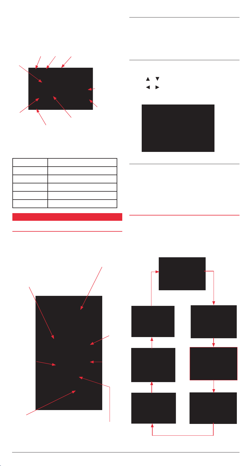
downloaded that signal bar will become solid. A hollow bar
indicates the receiver is not yet receiving a signal from that
satellite (it may be blocked by obstacles).
To access the satellite display page select SATELLITE
from the main menu.
Receiver Status
450 Elevation
North
Dilution of Precision
DOP (value).
Bars show
signal level.
Receiving /Using
Signal.
Downloading
Data.
0
5
Elevation
Satellite numbers being used
Altitude
for positioning are highlighted
on the display.
The following table shows the receiver status indicators that can
be displayed in the top left of the satellite page.
INDICATOR MEANING
2D 2D GS position fix
3D 3D GPS position fix
S2D 2D SBAS GPS position fix
S3D 3D SBAS GPS position fix
SIM Simulator mode
CONTROLS
USING THE KEYPAD
Cursor Keypad: Adjusts cursor position
First Press: Screen Zoom range.
Also escapes from
current function.
on screen. Selects
Menu items. Enters
alphanumeric data.
TURNING THE UNIT ON AND OFF (DIM/PWR)
To turn the GP450X on, briefly press the DIM/PWR key. The
unit will beep and turn on.
To turn the GP450X off, press and hold the DIM/PWR key for 3
seconds. The unit will count down then turn off.
ADJUSTING THE DISPLAY CONTRAST AND BACKLIGHT
(DIM/PWR)
To adjust the display brilliance and contrast, briefly press the
DIM/PWR key.
Press the
Press the
or keys to adjust the Brilliance.
or keys to adjust the contrast.
Press the ENT key to exit and save the new settings.
MARK/MOB
Briefly press the MARK/MOB key to save the current location
as a Waypoint.
Press and hold the MARK/MOB key to store your current
location as an MOB (Man Over Board) Waypoint. You will be
offered an option to immediately navigate back to the point.
CYCLING THROUGH THE DISPLAYS (DISP)
Briefly press the DISP key to cycle through the available
navigation screens. The GP450X has seven display modes –
Plotter, Highway, Steering, Compass, Navigation Data, and
two user configurable display options - Big Numbers
and Speedometer.
Second Press: Accesses Main
Menu options.
Accepts
selected
menu items.
Cycles through
Navigation
Display screens.
Selects or
cancels a
destination.
Turns unit On or OFF.
Allows adjustment of
screen contrast and
backlight brilliance.
Short Press: Marks your current
position as a waypoint.
Long Press: Marks your current
potion as an MOB point.
PAGE 4 INSTRUCTION MANUAL GP450X
Page 5

GP450X INSTRUCTION MANUAL PAGE 5
Plotter Display
The plotter display shows your ships position, track history,
bearing and range to target, course and speed over ground and
zoom range.
Bearing
Range to
Target
Waypoint
Vessel
Speed over
Course over
Ground
Ground
Screen
Range
Ship’s Position when Navigating Cursor
Position when Cursor is displayed.
The Plotter page allows you to view your current location. It also
displays a record of your track along with nearby Waypoints. The
‘ship’ on the screen shows your present position and heading
(the bow of the ship points in the direction of travel. At the
corners of the screen are displayed the Bearing (BRG), Range
(RNG), Course over Ground (COG) and Speed Over Ground
(SOG) relative to your destination. Your present Latitude and
Longitude is displayed at the bottom of the screen.
If the unit is in ‘cursor’ mode, the Latitude and Longitude will
display the position of the cursor on the screen and the BRG
and RNG will display values relative to the cursor.
HIGHWAY DISPLAY
The highway display provides a 3D view of your own vessel’s
progress towards a destination (Waypoint), along with
associated navigation data.
Destination
Waypoint
location. Moves
forward as your
vessel nears
its destination.
Bearing
from your
vessel to
destination
waypoint.
Direction you need to Steer to
return to the correct course.
Appears to the right or left of
the centreline depending on
steering direction required.
Destination (cursor or waypoint name).
NAVIGATION DATA DISPLAY
The Navigation display provides a sliding compass scale. The
vessel arrow in the centre shows your vessel’s present compass
heading. The Waypoint Marker shows the direction of your
destination Waypoint relative to your track.
Bearing reference
(Magnetic or True).
Destination (CURSOR or
Waypoint name).
Destination
Marker.
Time
Receiver
Status.
Speed over
Ground.
Compass
Scale.
Vessel
Course
over
Ground.
Range from
your vessel to
destination.
Time to Go (TTG)
to destination.
Note:
The compass scale requires your vessel to be moving in
Estimated Time of Arrival
(ETA) at destination.
Bearing
order to determine your direction. It does not work while your
vessel is stationary.
The centre of the page features a sliding compass scale that
shows your course over ground (current track) while you are
moving. Your present course over ground is indicated by the
vessel pointer in the centre of the display. A destination marker
shows the Bearing to your destination Waypoint relative to your
current track (COG). The compass scale and Waypoint marker
work independently to show at a glance the direction of your
movement and direction to your destination.
e.g. if the destination marker is to the left or right of your
vessel’s current track you should steer towards the marker until
it is directly above your vessel’s pointer. Once your vessel’s
pointer is aligned with the destination marker, you are travelling
towards your destination.
COMPASS DISPLAY
Course over
Ground marker.
Waypoint name
Waypoint Symbol
Speed over
Ground.
Course over
Ground.
Highway
Range from
vessel to
destination.
Course over
ground.
Bearing to
destination.
Speed over
ground.
Boat Mark – displays course as follows:
When waypoint is set, arrow shows
boats course towards destination.
When no waypoint is set, mode is North Up and
arrow shows boats course towards destination.
Digital XTE
Compass Ring
Bearing Pointer
Bearing Marker
When a destination is set the compass page will guide you to
your destination with digital readouts and a graphic compass
display which includes a bearing pointer. The Compass page is a
good alternative to the highway page when travelling at slower
speeds or when making frequent directional changes such as
when straight line navigation is not possible due to obstructions
Analogue Cross Track Error (XTE) Scale.
Arrow shifts with vessels XTE. When the
arrow is aligned with the centreline, the
boat is on course. Arrow blinks if vessel’s
XTE is greater than the XTE scale. ‘N’
(North) is displayed instead of arrow
when no destination is set.
or terrain.
Note that the compass page requires your vessel to be moving
in order to determine your direction. It does not work while your
vessel is stationary.
The centre of the page features a rotating compass that shows
your course over ground (current track) while you are moving.
Your present course over ground is indicated at the top of the
Range from your vessel to Destination waypoint.
compass ring. A Bearing Pointer in the centre of the compass
Page 6

ring points to your destination Waypoint relative to your
current track (COG). The compass ring and Bearing Pointer
work independently to show at a glance the direction of your
movement and direction to your destination.
e.g. if the Bearing Pointer points Up you are travelling directly
towards your destination. If the Bearing Pointer points in any
other direction you must turn towards the pointer until it points
Up in order to continue towards your destination.
POSITIONAL NAVIGATION DATA DISPLAY
Receiver Status
TimeDate
Each field can be individually configured to display
• Time
• Speed over Ground (SOG),
• Cross Track error (XTE)
• Odometer Distance
• Position
• Course over Ground (COG)
• Time to Go (to Destination) (TTG)
• Trip Distance
• External Voltage (Volts)
• Range and Bearing to Waypoint
• Estimated time of Arrival (ETA)
SPEEDOMETER DISPLAY
Speed over
ground.
The positional navigation data display provides GPS status,
position in Latitude and Longitude, course over ground, speed
over ground and the time and date. This page is useful for
determining your current location for relaying to others or for
simply confirming the current time or date.
Course over
Ground.
Position in Latitude
and Longitude.
USER CONFIGURABLE NAVIGATION DISPLAYS
There are two User Configurable Navigation displays that
can be set either as ‘Big Number’ navigation fields or as an
analogue Speedometer.
Big Number Navigation Display
Field 1
e.g. External Voltage
Field 3
e.g. Trip Meter
The ‘Big Number’ Navigation display is used to show digital
navigation information. It can be configured into 1, 2, 3 or 4
separate fields on the screen as shown below.
Field 2
e.g. Speed over Ground.
Field 4
e.g. Course over
Ground.
Speed Pointer
The Speedometer displays Speed over Ground. The display
can be configured to suit the speed limitations of your vessel
or the speed range of a specific application (such as trolling).
The Speedometer has 5 interval calibrations from minimum
to maximum. Simply set the minimum speed and the interval
speed and the Speedometer will be calibrated automatically.
The example above shows the minimum speed set to 0 knots
with the intervals set to 10 knots resulting in a Speedometer
calibrated from 0 to 40 knots with 10 knot intervals.
Analogue Speed dial
Digital Speed
CONTROLLING THE PLOTTER DISPLAY
Display Range
You can select the display range (Zoom Level) on both the
plotter and highway displays.
On the plotter screen the horizontal display range is shown in
the lower left corner of the display. The range of the plotter
display can be set from 0.02 to 320 display units. The display
units can be preset to nautical miles, kilometres or statute miles.
For maximum display range set the units to nautical miles to
provide a maximum range of 320 nm.
On the highway screen the zoom range can be set from 0.2 to
16 display units.
Selecting the Display range
With the plotter or highway window selected;
1. Press the MENU key. The ZOOM, SHIP TO CENTRE menu
appears and ZOOM IN/OUT is highlighted.
One Field
Three Fields Four Fields
PAGE 6 INSTRUCTION MANUAL GP450X
Two Fields
Page 7

GP450X INSTRUCTION MANUAL PAGE 7
Note: The SHIP TO CENTRE option only appears when the
Plotter display was selected.
2. Press the ENT key to select the highlighted option. The Zoom
control window appears.
3. Press
4. Press ENT to exit and return to the main display.
Moving the Cursor
Press the Cursor keypad to activate the cursor mode and move
the cursor on the plotter display. The cursor moves in the
direction of the keypad arrow. To move the cursor diagonally,
press the keypad diagonally. To pan the entire screen beyond
the currently visible display area, move the cursor beyond the
edge of the display screen.
Cursor Turned On
When the Cursor mode is active the cursor ‘cross’ is displayed
on the screen and the cursor position is displayed in latitude
and longitude at the bottom of the display. The range and
bearing from your vessel to the cursor is displayed in the upper
corners of the display. You can use the Cursor mode to explore
the plotter screen by panning the display or you can move the
cursor to a specific position to store as a Waypoint or select as
a destination.
Note: When the Cursor mode is active, the display will
remain at the cursor position. If your vessel is moving the
vessel icon may move off the screen and be no longer
visible. To re-locate the display to your vessel’s position see
’Centering your Vessel’s Position’ further below.
Cursor Turned Off
When the cursor is off the plotter displays your vessel on the
screen and your vessel’s latitude and longitude at the bottom of
the display. Navigation data is displayed at the screen’s corners.
If the track function is turn on, a trail showing a record of your
vessel’s movements is shown on the screen.
Centering your Vessel’s Position.
If your vessel is no longer visible on the screen, you can relocate
the display to your vessels position as follows:
1. Press the MENU key,
2. Select SHIP TO CENTRE then press ENT.
The Plotter screen will be restored with the vessel in the centre
of the display.
Track Recording
Your GP450X can record a log of your vessel’s movements. Track
points are stored in memory at regular intervals and displayed
on the screen as a trail extending behind your vessel. The
points are stored at distance intervals determined by settings
in the Plotter Setup menu. A shorter interval allows more track
points to be recorded which provides a more detailed log but
uses more memory resulting in a shorter storage time. A longer
interval will allow much longer recordings but there will be less
detail. Once the track memory becomes full, the current track
log will overwrite the oldest track points with newer points. If
track recording is not required it can be turned off.
to zoom out or to zoom in. The plotter or highway
window changes automatically to represent the new
range selection.
WAYPOINTS
In navigation terminology a Waypoint is a particular location
on a voyage. It can be a start point, a destination or an
intermediate location along the way. Your GP450X can store up
to 999 Waypoints.
Waypoints can be entered into your GP450X in one of
three ways;
• from the cursor position,
• from your vessels own current position or
• by manually entering a known latitude and longitude.
ENTERING A WAYPOINT FROM THE
CURSOR POSITION
On the Plotter display, use the cursor keypad to place the cursor
at the location desired for the Waypoint. You can select the
position by reading the latitude and longitude from the bottom
of the screen or alternatively, create a position by moving the
cursor to a point that is a specific distance and bearing from
your vessel’s current location as indicated by the fields in the
upper left and right of the display.
With the cursor at the desired location, press the ENT key.
The Waypoint entry window appears and a default numerical
Waypoint name is displayed.
Waypoint Name Entry Window
1. To accept the default Waypoint name simply press ENT.
2. To change the default Waypoint name, press the
keys to change the character at the cursor position. Press
the or keys to move the cursor position left or right.
The Waypoint name may consist of up to six alphanumerical
characters. When the required name is displayed press the
ENT key.
The Waypoint attribute page appears showing the position,
Waypoint symbol, time and date and arrival information for your
new Waypoint. To accept the default fields press ENT.
Waypoint Attribute Window
To edit the other Waypoint properties, see section on Editing
Waypoint Attributes on page 8.
or
Default
Waypoint
Name.
MARKING A WAYPOINT AT THE VESSELS POSITION
1. To mark your vessels present location, briefly press the MARK
key. Your current location is automatically saved to memory
with a default numerical Waypoint name and the Waypoint
attribute page is displayed to allow you to edit the Waypoint’s
properties if you wish. EXIT is highlighted.
2. To accept the default Waypoint name and attributes simply
press ENT to finish.
To edit the Waypoint properties, see section on Editing
Waypoint Attributes on page 8.
ENTERING A WAYPOINT FROM THE WAYPOINT LIST
1. Press the MENU key to access the main menu. Highlight
the WAYPOINTS option and press ENT. The Waypoint list
options are displayed.
Page 8

2. Press ENT to select the LIST option. The Waypoints list
CREAT E?
RENAME?
FISH01
page is displayed showing all of your Waypoints listed in
alphabetical order. NEW is highlighted.
Changing the Waypoint Name
1. Press the
press ENT.
2. Press the
position and the or keys to move the cursor position left
or right. Press ENT when done. The window below appears.
or keys to highlight the Waypoint name and
or keys to change the character at the cursor
NOTE: There are three default systemgenerated waypoint names.
Waypoint List
3. To create a new Waypoint, press ENT to select the NEW
option. The Waypoint entry window appears and a default
numerical Waypoint name is displayed.
Waypoint Name Entry Window
4. To accept the default Waypoint name simply press ENT.
5. To change the default Waypoint name, press the
to change the character at the cursor position. Press the or
keys to move the cursor position left or right. The Waypoint
name may consist of up to six alphanumerical characters.
When the required name is displayed press the ENT key.
6. The Waypoint attribute window appears showing the position,
Waypoint symbol, time and date and arrival information for
your new Waypoint. To accept the default fields and store the
Waypoint press ENT.
To edit the rest of the Waypoint properties, see section on
‘Editing Waypoint Attributes’ below.
CURSOR: The last
destination set
using the cursor
position.
MOB: The last
Man Overboard
position set by the
MOB key
.
START: Your
starting point
when the last
destination was
selected.
or keys
EDITING WAYPOINT ATTRIBUTES
When creating a new Waypoint from the Cursor position, from
your Vessel’s position or from the Waypoint List, the Waypoint
Attribute page is displayed. This page is filled with default
Waypoint information including the position, Waypoint symbol,
time and date and arrival information for your new Waypoint.
To accept the default fields and store the Waypoint press ENT,
otherwise follow the steps below to edit the Waypoint attributes.
3. Press
Changing the Waypoint Symbol (Mark)
The Waypoint symbol appears on the plotter display to mark the
location of your Waypoint. You can select from nine different
Waypoint symbols to help categorise your Waypoints.
1. Press the
2. Use the
3. When the required symbol is displayed press the ENT key
Changing the Comments Field
The Date and Time field can be replaced with a comment if
required. A maximum of 16 characters is available.
1. Press the
2. Press the
Setting the Log Route Function
The Log Route function adds the Waypoint to the active route.
For more details on this feature please refer to the
Routes section.
to highlight RENAME then press ENT. The original
Waypoint name will be overwritten with the new name.
or and or keys to highlight the currently
displayed symbol (the default symbol is X. Press the ENT key.
or keys to scroll through the list of symbols. The
following symbols are available.
or keys to highlight the Date and Time field
and press the ENT key.
or keys to change the character at the cursor
position and the or keys to move the cursor position
left or right. To create a ‘space’, choose the ‘blank’ character.
Press ENT when done.
MARKING AN MOB
The MOB mark denotes a ‘Man Overboard’ position. It allows
you to instantly mark your current location in an emergency and
quickly get navigation instructions back to it. The MOB location
is stored in the Waypoint list as MOB. Only one MOB point can
be stored. Each time you save a new MOB point the previous
MOB is overwritten.
1. To save your current location as an MOB point press and
hold the MARK/MOB key. The MOB point is saved and the
following screen appears offering to navigate you back to the
MOB point.
Comment Field
TTG & ETA calculated according to
TTG/ETAspeed in plotter setup.
PAGE 8 INSTRUCTION MANUAL GP450X
Waypoint Name
Waypoint Symbol
Saving an MOB point
2. To navigate to the MOB point press the
YES then press ENT. The plotter page will appear with the
key to select
Page 9

GP450X INSTRUCTION MANUAL PAGE 9
MOB position shown as your destination and the required
navigation data shown in the corners of the screen.
Bearing and Range to MOB point
Your Vessel
Vessel’s Course
Proximity Alert Area
Vessel
Route to
MOB
Plotter display with MOB set as destination
Note: If you don’t wish to immediately navigate to the MOB
point, simply press ENT to accept the NO option. The point will
remain in the Waypoint list in case you wish to navigate to it later.
MOB point
NEAREST WAYPOINTS
The Nearest Waypoints list displays the Waypoints that are
closest to your present location. It is useful for quickly finding
nearby locations such as safe harbours, fuel, boat ramps or
even fishing spots etc that you have previously stored in the
Waypoint list.
To view the nearest Waypoints, from the main menu, choose
WAYPOINTS and press ENT. Select NEAREST from the list
and press ENT. A Waypoint list is shown with the nearest
Waypoints at the top of the list along with their range and
bearing from your present location.
Waypoints listed by Nearest
To display the TTG (Time To Go) and ETA (Estimated Time of
Arrival) to each Waypoint press the
Waypoints listed by TTG and ETA
To return to the Waypoint by distance list press the
the MENU key to close the Nearest list and return to the Menu.
key.
key. Press
PROXIMITY WAYPOINTS
A Proximity Waypoint is a Waypoint to which a proximity alarm
has been applied. The alarm effectively places a ‘circle’ around
that location. If you enter the area of the circle the alarm will
trigger to warn you of your close proximity to that Waypoint.
Proximity Waypoints are useful for warning of dangerous
locations such as rocks, shallow water or other hazardous
places. The Proximity Waypoint list in your GP450X can store up
to 10 Proximity Waypoints.
Alarm triggers here
Proximity Waypoint
1. To access the Proximity Waypoint page, from the main menu,
select WAYPOINTS and press ENT.
2. Select PROXIMITY and press ENT. The Proximity Waypoint
list is displayed.
Proximity
Waypoint
Name.
Active
Proximity
Alert.
Range
to active
Proximity
Waypoint.
If you have not yet created any proximity Waypoints the list will
be blank otherwise any Proximity Waypoints you have created
will be listed. The Waypoint name is displayed on the left. On
the right is the distance (circle radius) from the Waypoint at
which the alarm will trigger.
While viewing the Proximity Waypoint list, if a Proximity alarm
is triggered, an exclamation mark will flash to the right of the
affected Waypoint to identify it in the list. The range from your
vessel to that Waypoint will also be displayed.
3. To add a Proximity Waypoint, use the
highlight the first blank Waypoint position and press ENT. The
standard Waypoint list is displayed.
4. Select the required Waypoint and press ENT. The screen
returns to the Proximity Waypoint list. A default alarm
distance is applied automatically.
NOTE: You must have first stored the required location as
a Waypoint.
5. To change the distance at which the alarm will sound,
highlight the Waypoint’s alarm distance and press ENT.
6. Use the
position and the or keys to move the cursor position
left or right.
7. Press ENT when done.
Proximity Waypoint List
or keys to change the number at the cursor
Alarm Distance
Preset Alarm
Distance.
Indicates
the Alarm
has been
triggered
on this
Waypoint.
or keys to
EDITING THE PROXIMITY WAYPOINT LIST
To edit the Proximity Waypoint list, highlight the Waypoint you
wish to edit and press ENT.
• Select REVIEW to display or edit the standard properties of
that Waypoint (such as location, symbol or comments etc).
• Select REMOVE to delete that specific Waypoint from the
Proximity List. Note the Waypoint is only removed from
the Proximity list, the original Waypoint still remains in the
normal Waypoint list.
• Select CLEAR ALL to delete ALL Waypoints from the
Proximity list.
Page 10

ERASING WAYPOINTS
1. At the main menu, highlight ERASE and press the ENT key.
The Erase screen appears.
2. The WAYPOINTS/MARKS option is highlighted by default.
Press the ENT key. The ERASE WPTS/MARKS screen is shown
listing your current Waypoints.
3. To erase individual Waypoints, use the cursor keys to select
the required Waypoint name then press ENT. The Waypoint
properties window appears for the selected Waypoint.
4. Press the
The Waypoint is immediately erased.
key to select the ERASE option and press ENT.
Example Route along a River
CREATING ROUTES
The GP450X can hold up to 50 stored routes plus one Route
Log. Each route may contain up to 30 Waypoints. If you attempt
to store more than 30 Waypoints a message will inform you that
you can no longer save additional Waypoints to that route.
A route may be constructed in one of four ways;
• from the cursor
• from the Waypoint list
• from the route list or
• storing your current position either automatically or manually.
CREATING A ROUTE USING THE CURSOR
1. With the plotter screen displayed, use the cursor keypad
to place the cursor at the location of the first Waypoint
(the latitude and longitude of the cursor is displayed at the
bottom of the screen).
2. Press the ENT key. The following window appears.
Note: You cannot erase system generated Waypoints such as
CURSOR, MOB or START
5. To erase ALL the Waypoints in your unit, highlight the ALL?
option and press ENT. You will be asked to confirm
your selection.
6. Press the
Waypoints will be deleted leaving just the system generated
Waypoints CURSOR, MOB and START.
key to select YES then press ENT. All your
ROUTES
Often a trip from one place to another involves several course
changes requiring a series of Waypoints. This sequence of
Waypoints leading you to your destination is called a route.
Your GP450X can be programmed to traverse a sequence of
Waypoints, automatically advancing to the next Waypoint as
you progress, so you do not have to repeatedly switch to the
next Waypoint. You can also travel the route in the opposite
direction, using it to return back home again.
The cursor will be on the second line ready to edit the
Waypoint name if required. A default Waypoint name is
offered which is the lowest Waypoint number currently
available in your unit.
3. If you are happy to use the default Waypoint number
supplied, simply press ENT to register the Waypoint under
that number.
If you prefer to change the Waypoint name then use the
keys to change the character at the cursor position and the
or keys to move the cursor position left or right.
The Waypoint name can have a maximum of 6 characters. Press
ENT when done.
The Waypoint attribute window is displayed.
4. If required, you can change the latitude and longitude
and Waypoint Icon (Mark). You can also replace the time
and date with a comment (up to 16 characters). Once any
required changes are completed, select LOG RTE and press
the ENT key. This will store the Waypoint into the Route Log
memory.
or
PAGE 10 INSTRUCTION MANUAL GP450X
Page 11

GP450X INSTRUCTION MANUAL PAGE 11
5. Repeat the steps above to log additional Waypoints to the
LOGGED ROUTE 001 003
Route Log memory.
6.
Once you have entered and logged all the required Waypoints
for that route, press the MENU key twice to access the main
menu. Select ROUTES and press the ENT key.
7. The ROUTE menu will show the assembled route under the
LOG heading. The route will be automatically labelled using
the first and last Waypoints in the route.
Route Menu
8. To save the route, highlight the LOG route (001 -> 003
in the example above) and press the ENT key. The Route
processing options are displayed.
Route Entry Window
3. Press the ENT key. Use the or keys to scroll through the
characters at the first cursor position. As you scroll through
the characters your GP450X looks for stored Waypoints
matching the characters you select and displays them. If
more than one Waypoint exists with the same first letter (e.g.
RAMP and RAMP2) use the or keys to move the cursor
position left or right to select other letters that spell the name
of the Waypoint you require.
4. When the required Waypoint name is displayed (RAMP in
this example), press ENT. The next Waypoint position 02
is highlighted. Repeat the steps above to select the next
Waypoint (FISH1 in this example). Press ENT when done. You
should now have two Waypoints stored in the route.
Route Processing Options
9. Select MOVE and press the ENT key. The route will be
moved from the Route Log memory to the first available
sequential route number and the Route Log will listed
as empty.
Route Log
If you wish to edit the route later on, follow the steps described
under EDITING ROUTES later in this section.
CREATING A ROUTE FROM THE ROUTE MENU
The following process describes how to create a route using two
Waypoints already stored in the Waypoint list. In this example
the Waypoints are called RAMP and FISH1.
1. From the main menu select ROUTES and press the ENT key.
The Route list is displayed.
Route List
2. Select NEW and press the ENT key. The Route Entry screen
appears (next column).
The route automatically uses the first available route number
(Route 02 in the following example). The first Waypoint
position 01 is highlighted by default.
5. If you enter a Waypoint name that is not in the Waypoint list
your GP450X screen will show the following message:
Press
to choose YES then press the ENT to create a new
Waypoint (or choose NO to return to the Route entry screen).
6. The Waypoint attribute edit window is displayed. Edit the
latitude, longitude Icon (Mark) and comments as necessary
then select EXIT and press ENT to return to the Route/
entry screen.
CREATING ROUTES FROM THE WAYPOINT LIST
This method is very similar to the method described for creating
routes from the cursor.
1. From the main menu select WAYPOINTS and press the
ENT key.
2. Choose LIST or NEAREST and press the ENT key.
The Waypoint list is displayed.
3. Choose a Waypoint from the list and press the ENT key.
The Waypoint attribute page is displayed.
4. Choose LOG RTE and press the ENT key.
5. Repeats steps 3 and 4 to build the route.
6. When the route is completed press the MENU key once to
return to the main menu then select ROUTES. The route you
have assembled is stored under the LOG heading.
7. Highlight the LOG route and press the ENT key.
Page 12

8. Select MOVE and press ENT. The route will be saved in the
next available route memory and the LOG route will
be cleared.
9. Press the MENU key twice to exit.
CREATING A TRACK-BASED ROUTE
There are two methods by which you can create a track-based
route; either by the manual input of track points using the
MARK/MOB key or by the automatic inputting of track points
from the ROUTES menu. A track-base route is very handy for
retracing your track.
Manual Method
This method creates a route by storing a position each time the
MARK/MOB key is pressed. Each time you alter your course,
store a new position to mark that location. Your GP450X will
create a route from these points that can be used for future
navigation or as a route to follow when returning home.
1. Press the MARK/MOB key momentarily. The Waypoint
attribute window is displayed.
NOTE: Since each route has a limit of 30 Waypoints, you should
choose intervals that will extend the route to last the length of
your trip. If you need to use smaller intervals you may need to
save the points over several routes.
6. Select VOYAGE ROUTE and press the ENT key. Select
START and press the ENT key.
The GP450X will begin storing points according to your settings,
starting with your current position. If you wish you can press
MENU twice to return to your previous navigation screens. The
GP450X will continue to log points in the background. Each
time a new point is saved, ‘XXX SAVED’ (where XXX is the
Waypoint number) will be displayed at the top of the screen.
When 30 Waypoints have been saved a message will inform you
that you have reached the maximum number of Waypoints for
your route and you can no longer save any more points. If this
happens, press the ENT key to erase the message.
To manually stop saving positions;
1. From the main menu select ROUTES.
2. Select VOYAGE ROUTE and press the ENT key.
3. Select STOP.
The route is automatically saved under the LOG route memory
in the ROUTES menu.
2. Change the name, comment and Waypoint Icon (Mark) if
desired, otherwise accept the defaults.
3. Select LOG RTE and press the ENT key
4. Repeat steps 1 to 3 each time you change your heading so
that another Waypoint is stored at that location. Up to 30
positions can be saved into the route.
5. When you have entered all the positions you need, use the
MENU key to access the main menu. Select ROUTES and
press the ENT key.
6. Highlight the LOG route and press the ENT key.
7. Select MOVE and press the ENT key. The route is moved and
stored in the next available route memory.
8. Press the MENU key twice to exit.
Automatic Method
This method creates a route by automatically storing positions
at intervals of time or distance. Up to 30 positions can be saved
into the route
1. Use the MENU key to access the main menu.
2. Select ROUTES and press the ENT key.
To store the route;
1. Use the MENU key to access the main menu.
Select ROUTES and press the ENT key.
2. Highlight the LOG route and press the ENT key.
3. Select MOVE and press the ENT key. The route is moved and
stored in the next available route memory.
4. Press the MENU key twice to exit.
EDITING ROUTES
Replacing Waypoints in a Route
To replace a Waypoint with another Waypoint from your
Waypoint list:
1. Use the MENU key to access the main menu.
2. Select ROUTES and press the ENT key.
3. Select the route you wish to edit and press the ENT key.
The route list is displayed.
4. Highlight the Waypoint you wish to replace and press the
ENT key.
5. The route edit window appears.
3. Select INTERVAL and press the ENT key.
4. Select TIME or DISTANCE as the method by which the
position will be stored and press the ENT key.
5. Use the cursor keys to set the value for the time or distance
interval and press the ENT key.
For Example;
To record a point every 15 minutes, set the interval to TIME and
set the value to 00H 15M.
To record a point every 2 km, set the interval to DISTANCE and
set the value to 02.0 km
PAGE 12 INSTRUCTION MANUAL GP450X
6. Select CHANGE and press the ENT key. The Waypoint
attribute window appears.
7. Highlight the Waypoint name and press the ENT key. Use the
cursor keys to select a new saved Waypoint name. Press the
ENT key when done.
Route Menu Window
Page 13

GP450X INSTRUCTION MANUAL PAGE 13
8. Select EXIT and press the ENT key to return to the route
CHANGE ?
REMOVE ?
list – or simply press the MENU key twice to return to your
navigation screen.
Note: When changing the Waypoint name, if you enter a name
that doesn’t exist in your Waypoint list, you will be asked to
either CREATE a new Waypoint or RENAME the
current Waypoint.
Permanently Deleting a Waypoint from a Route
1. Use the MENU key to access the main menu.
2. Select ROUTES and press the ENT key.
3. Select the route you wish to edit and press the ENT key.
4. Highlight the Waypoint you wish to delete and press the ENT
key. The route edit window appears.
Route Menu Window
5. Select REMOVE from the route edit menu and press the
ENT key.
6. Press the MENU key twice to exit.
6. Press the MENU key twice to finish.
Temporarily skipping a Waypoint within a Route
If required, you can temporarily skip a Waypoint from within a
route. In the example below Waypoint 002 has been skipped
causing the route to bypass that Waypoint. The Waypoint
remains in the route list but is not used in the route.
Waypoint 002 is included in the route
Inserting a Waypoint into a Route
To insert a Waypoint into a route
1. From the main menu select ROUTES.
2. Select the desired route and press the ENT key.
3. Select the Waypoint that will come AFTER the Waypoint you
are inserting and press the ENT key. For example, to insert
a Waypoint between Waypoints RAMP and 001 in the
example below, select 001 and press ENT
4. The route edit window appears. Choose INSERT and press
the ENT key.
Waypoint 002 has been skipped
To skip a Waypoint;
1. At the main menu select ROUTES and press the ENT key.
2. Select the desired route and press the ENT key.
3. Highlight the name of the Waypoint you wish to deselect and
press the ENT key.
4. Select SKIP from the Route Edit window and press the
ENT key.
5. X appears to the left of the skipped Waypoint. The route will
now bypass the skipped Waypoint.
6. Press MENU twice to return to the navigation screen.
To restore the skipped Waypoint
1. Repeat the steps above and select SKP oFF from the Route
Edit Window at step 4, then press the ENT key.
Route Menu Window
4. Use the cursor keypad to select the name of the Waypoint
you wish to insert. For example to insert a Waypoint called
MARKER use the
the cursor position to M. The Waypoint called MARKER
should appear.
5. Press the ENT key. The new Waypoint will be inserted into
the route as shown below.
or keys to change the character at
2. The Waypoint is now restored and will be included in the
route. Press MENU twice to exit.
Page 14

Changing a Route Comment
You can change the comment (name) of a route as follows. Up
to 16 alphanumeric characters can be used.
1. From the main menu select ROUTES and press the ENT key.
2. Select the required route and press the ENT key.
3. Choose CMNT and press the ENT key.
4. Use the cursor keypad to enter the required comment
(name). Use the
the cursor position and the or keys to move the cursor
position left or right.
5. When the required comment has been entered press the
ENT key.
6. Press MENU twice to return to the navigation screen.
or keys to change the character at
ERASING ROUTES
To erase a route;
1. From the main menu select ERASE and press the ENT key.
2. Select ROUTES and press the ENT key.
3. Select the route you wish to erase and press the ENT key.
NOTE: If you want to erase all the route select ALL and press
the ENT key
4. The ERASE ROUTE option window appears. Select YES and
press the ENT key.
5. The select Route will be erased.
6. Press the MENU key twice to return to the
navigation screen.
3. Use the cursor keypad to move the cursor to the desired
location to be used for your destination.
The destination can be determined either by reading the
latitude and longitude from the bottom of the screen or as a
Range and Bearing from your current location using the fields
at the top corners of the screen.
4. Once the cursor is in the correct location press the ENT key.
CURSOR is displayed at the cursor location and a dotted line
connects your ships current position with the cursor position
as shown below.
Destination set by Cursor
SETTING DESTINATIONS BY WAYPOINT
This method uses a Waypoint from your Waypoint list as
your destination.
1. Press the GOTO key.
2. Select either WPT-LIST? or WPT-NEAR and press the
ENT key.
NOTE: WPT-LIST displays a list of all your Waypoints. WPT-NEAR
displays the Waypoints closest to your present location.
3. Choose a Waypoint and press the ENT key
SETTING DESTINATIONS
Destinations can be set in one of four ways;
• by Cursor
• by Waypoint
• by Route
• by MOB
Use the GOTO key to set a destination as shown below.
SETTING DESTINATIONS BY CURSOR
This method uses the location of the cursor as your destination.
1. Press the GOTO key. The GOTO option screen appears.
2. Select CURSOR? and press the ENT key. The plotter screen
appears with a ? to the right of the cursor.
4. The plotter screen will appear with a dotted line extending
from your ships position towards the selected Waypoint.
Navigating to Waypoint
NOTE: If the selected Waypoint is not visible, its range may be
beyond the selected zoom range of the screen and the dotted
line will extend off the screen towards the Waypoint.
Navigating to Waypoint
beyond zoom range
SETTING DESTINATIONS BY ROUTE
1. Press the GOTO key
2. Select ROUTE? and press the ENT key. The Route list
is displayed.
PAGE 14 INSTRUCTION MANUAL GP450X
Page 15

GP450X INSTRUCTION MANUAL PAGE 15
Route List
3. Select a route from the list and press the ENT key. The Route
Direction window appear.
Route Direction Window
4. Choose FORWARD or REVERSE to select the route
direction. Choosing FORWARD will guide you along the
route starting from the first Waypoint in the route and ending
at the last. Choosing REVERSE guides you back along
the route in the opposite direction, starting from the last
Waypoint and ending at the first. The REVERSE option can
be useful for finding your way back home at the end of
the day.
SETTING DESTINATIONS BY MOB
Normally when you save an MOB you are offered an option to
immediately navigate to it. If you choose not to do so, you can
use the GOTO function to call up the MOB later on.
1. Press GOTO
2. Select WPT-LIST? and press the ENT key.
2. Choose the MOB Waypoint and press the ENT key.
3. The plotter screen will appear with a dotted line extending
from your ship’s position towards the MOB point.
SETTING USER WAYPOINTS AS A DESTINATION
You can insert a User Waypoint into the GOTO Options list. This
allows you to quickly select a commonly used Waypoint
for navigation.
For example you could save the location of your local Boat
Ramp as a Waypoint then insert this into the GOTO Options
list. This makes your boat ramp Waypoint easy to find when you
need to navigate yourself back to the ramp at the end of
the day.
1. Press GOTO. The GOTO options window appears.
reappears and your selected Waypoint (RAMP) is now listed
as a GOTO Waypoint.
New GOTO
Waypoint
Symbol
GOTO Options window with new User
Waypoint (RAMP) inserted
4. Press MENU to exit and return to the navigation screens.
To navigate to your user Waypoint at any time, simply press
GOTO, select your User Waypoint and press the ENT key. The
plotter screen will appear with a dotted line extending from
your vessel to the User Waypoint.
CANCELLING YOUR DESTINATION
You can cancel your selected destination as follows;
1. Press the GOTO key.
2. Select OFF? and press the ENT key.
3. The plotter screen will reappear and the selected Waypoint
and dotted navigation line will no longer be visible.
ALARMS
Your GP450X has a number of alarm conditions that can
generate both visual and audible alarms. The available
alarms are;
• Arrival Alarm
• Anchor Watch Alarm
• Cross Track Error (XTE) Alarm
• Speed Alarm
• Trip and Odometer Alarm
• SBAS Alarm
When an alarm is activated the buzzer sounds and the name
of the offending alarm appears on the display along with an
alarm Icon. To silence the buzzer and remove the visual alarm
notification, simply press any key. The alarm Icon remains on the
screen until the reason for the alarm is cleared.
Message Board
In some instances, multiple alarms may be triggered. These
alarm messages can be viewed on the Message Board.
To view the message board;
1. From the main menu, select MESSAGES and press the
ENT key
2. Current messages will be listed.
2. Select SETUP and press the ENT key. The Select User
Waypoint list appears.
Message Board
For more information about the message board please refer to
the MAINTENANCE section later in this manual.
3. Select the desired Waypoint (RAMP is selected in the
example) and press the ENT key. The GOTO window
Page 16

NOTE: The arrival and anchor watch alarms cannot both be
activated at the same time.
ARRIVAL AND ANCHOR WATCH ALARMS
Arrival Alarm
The arrival alarm alerts you when your vessel is approaching
a destination Waypoint. The area that defines the arrival zone
is a circle surrounding the destination Waypoint. The alarm is
triggered when your vessel enters the circle.
Arrival Alarm
Setting the Arrival Alarm
1. From the main menu select ALARMS and press the ENT key
2. Select the ARV/ANC field and press the ENT key.
Anchor Alarm
Setting the Anchor Watch Alarm
1. From the main menu select ALARMS and press the ENT key
2. Select the ARV/ANC field and press the ENT key.
3. The Arrival/Anchor Options list appears.
4. Select ANC and press the ENT key.
5. The Alarm Range field is automatically highlighted. Press the
ENT key.
6. Use the Cursor keypad to enter the alarm range. Use the
or keys to change the number at the cursor position and
3. The Arrival/Anchor Options list appears.
the or keys to move the cursor position left or right.
When finished press the ENT key.
7. Press MENU twice to exit and return to the
navigation screen.
When your vessel drifts beyond the range set here the buzzer
sounds and the message ANC ALARM! is displayed.
CROSS TRACK ERROR (XTE) ALARM
The XTE error occurs when your ship strays from its intended
course. The XTE is useful when navigating through narrow
4. Select ARV and press the ENT key.
5. The Alarm Range field is automatically highlighted. Press the
ENT key.
6. Use the Cursor keypad to enter the alarm range. Use the
or keys to change the number at the cursor position and
the or keys to move the cursor position left or right.
When finished press the ENT key.
7. Press MENU twice to exit and return to the
navigation screen.
When your vessel approaches a destination Waypoint at the
range set here the buzzer sounds and the message ARV
ALARM! is displayed.
Anchor Watch Alarm
The Anchor Watch alarm warns you that your anchored vessel is
moving excessively when it should be at rest. It works similarly
to the arrival alarm except that it alerts you when your vessel
leaves a circle rather than enters it. When setting the alarm
you should allow for the possible distance your vessel may
legitimately drift while at anchor. The alarm distance should
be set to warn if the anchor is dragging and your position is
moving excessively.
PAGE 16 INSTRUCTION MANUAL GP450X
channels or as a simple warning in case you are distracted
while navigating.
XTE Error Alarm
Setting the XTE Alarm
1. From the main menu select ALARMS and press the ENT key
2. Select the XTE field and press the ENT key.
3. The XTE Options list appears. Select ON and press the
ENT key.
4. The Alarm Range field is automatically highlighted. Press the
ENT key.
Page 17

GP450X INSTRUCTION MANUAL PAGE 17
5. Use the Cursor keypad to enter the alarm range. Use the
or keys to change the number at the cursor position and
the or keys to move the cursor position left or right.
When finished press the ENT key.
6. Press MENU twice to exit and return to the
navigation screen.
When your vessel strays from its intended course by the distance
set here, the buzzer will sound and the message XTE ALARM!
will be displayed.
SPEED ALARM
The speed alarm provides visual and audible alerts when the
ship’s speed is higher or lower than the alarm range setting.
Setting the Speed Alarm
1. From the main menu select ALARMS and press the ENT key.
2. Select SPEED and press the ENT key. The Speed Options
menu appears.
3. Choose LOW or HIGH and press the ENT key.
- The LOW settings sounds an alarm when the speed falls
below the Speed Alarm setting
- The HIGH setting sounds an alarm when the speed exceeds
the Speed Alarm setting.
4. The Speed Range field is automatically highlighted. Press the
ENT key.
5. Use the Cursor keypad to enter the alarm speed. Use the
or keys to change the number at the cursor position and
the or keys to move the cursor position left or right.
When finished press the ENT key.
6. Press MENU twice to exit and return to the
navigation screen.
When your vessel violates the speed alarm setting the buzzer
sounds and the message SPD ALARM! is displayed.
TIME ALARM
The time alarm works as an alarm clock to provide a visual and
audible alert at the set time.
Setting the Time Alarm
1. From the main menu select ALARMS and press the ENT key.
2. Select the TIME field and press the ENT key
3. Select ON and press the ENT key.
4. The Time setting field is automatically highlighted. Press the
ENT key.
5. Use the Cursor keypad to enter the alarm time. Use the
keys to change the number at the cursor position and the
or keys to move the cursor position left or right. When
finished press the ENT key.
6. The AM/PM indicator is automatically highlighted. Press the
ENT key.
7. Select AM or PM and press the ENT key.
8. Press MENU twice to exit and return to the
navigation screen.
When the preset time is reached the buzzer sounds and the
message TIME ALARM! is displayed.
5. Use the Cursor keypad to enter the trip distance. Use the
or keys to change the number at the cursor position and
the or keys to move the cursor position left or right.
When finished press the ENT key.
6. Press MENU twice to exit and return to the
navigation screen.
When the distance that your vessel has travelled exceeds the
preset distance, the buzzer sounds and the message TRIP
ALARM! is displayed.
ODOMETER ALARM
The Odometer Alarm is similar to the trip alarm. Whereas
the Trip Alarm can be reset regularly to monitor short trips
the Odometer Alarm can be left to accumulate much larger
distances over multiple trips.
Setting the Odometer Alarm
1. From the main menu select ALARMS and press the ENT key.
2. Select the ODOMETER field and press the ENT key
3. Select ON and press the ENT key.
4. The Odometer Distance field is automatically highlighted.
Press the ENT key.
5. Use the Cursor keypad to enter the odometer distance. Use
or keys to change the number at the cursor position
the
and the or keys to move the cursor position left or
right. When finished press the ENT key.
6. Press MENU twice to exit and return to the
navigation screen.
When your vessel has travelled further than the preset odometer
distance the buzzer sounds and the message ODOMETER
ALARM! is displayed.
BUZZER SELECTION
The buzzer sounds whenever an alarm is activated. You can
choose the buzzer parameters as follows;
1. From the main menu select ALARMS and press the ENT key.
2. Select BUZZER and press the ENT key. The Buzzer Options
menu appears.
3. Choose from SHORT, LONG or CONSTANT.
- SHORT provides three short beeps then stops.
- LONG provides three long beeps then stops.
- CONSTANT will beep continuously until cancelled by
pressing any key.
or
4. Press MENU twice to exit and return to the
navigation screen.
OTHER NAVIGATION FUNCTIONS
CALCULATING RANGE, BEARING, TTG AND ETA
Range and Bearing between two Waypoints
1. From the main menu select CALCULATE and press the ENT
key. The calculation window is displayed.
TRIP ALARM
The Trip Alarm is triggered when the distance travelled by your
vessel exceeds the distance preset in the Trip Alarm.
Setting the Trip Alarm
1. From the main menu select ALARMS and press the ENT key.
2. Select the TRIP field and press the ENT key
3. Select ON and press the ENT key.
4. The Trip Distance field is automatically highlighted. Press the
ENT key.
2. The MODE option is highlighted by default. Press the ENT
key to select.
3. The Mode Option menu appears. Choose WAYPOINTS and
press the ENT key.
Page 18

4. The FROM field is highlighted. Press the ENT key.
5. Use the Cursor keypad to select the first Waypoint from the
Waypoint list. Press the ENT key when done.
6. Highlight the TO field and press the ENT key.
7. Use the Cursor keypad to select the second Waypoint from
the Waypoint list. Press the ENT key when done.
8. Highlight the SPD field and press the ENT key.
9. Choose AUTO or MAN (Manual) and press the ENT key.
4. Highlight the Route Number (default is 01) and press the
ENT key.
5. Use the Cursor keypad to select the required Route number
then press the ENT key. The names of the Start and
Destination Waypoints of the selected route are displayed
along with the number of Waypoints in the route.
6. Highlight the SPD field and press the ENT key.
7. Choose AUTO or MAN (Manual) and press the ENT key.
- AUTO uses your vessel’s average speed.
- MAN uses a speed that you choose.
8. If AUTO was selected the TTG, ETA and Range are
automatically displayed at the bottom of the screen. These
values are calculated using your vessel’s average speed.
- AUTO uses your vessel’s average speed.
- MAN uses a speed that you choose.
10. If AUTO was selected the TTG, ETA, Range and BRG are
automatically displayed at the bottom of the screen. These
values are calculated using your vessel’s average speed.
Time to Go
Bearing
Range
Estimated Time of Arrival
11. If MAN was selected a speed field appears.
12. Press the ENT key to access the SPEED field. Use the
Cursor keypad to select the required speed value. Press the
ENT key when done.
13. The TTG, ETA, Range and BRG are displayed at the bottom
of the screen. These values are calculated using the speed
value you entered above.
14. Press the MENU key twice to return to the
navigation screen.
Range, TTG and ETA of a Route
This function calculates the Range, TTG and ETA between the
first and last Waypoints of a route.
1. From the main menu select CALCULATE and press the ENT
key. The calculation window is displayed
2. The MODE field is highlighted by default. Press the ENT key
to select.
3. The Mode Option menu appears. Choose ROUTE and press
the ENT key.
PAGE 18 INSTRUCTION MANUAL GP450X
Time to Go
Range
Estimated Time of Arrival
9. If MAN was selected a speed field appears.
10. Press the ENT key to access the SPEED field. Use the
Cursor keypad to select the required speed value. Press the
ENT key when done.
11. The TTG, ETA and Range are displayed at the bottom of the
screen. These values are calculated using the speed value
you entered above.
12. Press the MENU key twice to return to the
navigation screen.
MAIN MENU - CONFIGURING
YOUR GP450X
GPS SETUP
The GPS Setup menu smoothes position and course, averages
speed, applies position offsets and deactivates unhealthy
satellites.
Position Smoothing
If the GPS satellite signal condition becomes temporarily
unfavourable, the accuracy of the GPS position can be affected
to the point where your position on the plotter may appear to
move around even though your vessel is not moving. This effect
can be reduced by smoothing the raw GPS measurements so
that their effect on your navigation is minimised. The setting
range is from 0 to 999 seconds. The higher settings provide
more smoothing but will slow the time that the unit responds
to valid changes in position, especially at higher speeds. The
default setting is 0 seconds. Increase this setting if the GPS
position fix is changing greatly when you are not moving.
Speed and Course Smoothing
As with your position, your vessel’s speed and course is directly
measured using the GPS satellite signals. This means the raw
velocity data will be affected by unfavourable satellite signal
No of
Waypoints
in the Route
Start and
Destination
Waypoints
Page 19

GP450X INSTRUCTION MANUAL PAGE 19
conditions. You can reduce these affects by increasing the Speed
and Course smoothing. As with position smoothing, the higher
the value you select for Speed and Course Smoothing the more
smoothed will be the raw data. If the setting is too high the
response to speed and course changes will become slower. The
setting range is from 0 to 9999 seconds.
Average Speed (Speed Averaging)
Speed averaging over a period of time is useful for calculating
ETA (Estimated Time of Arrival) and TTG (Time to Go). If the
averaging period is too long or too short, the accuracy of the
ETA and TTG calculations will be affected. The default setting is
60 seconds. The available setting range is 0 to 9999 seconds.
LAT/LONG Offset
The Latitude and Longitude Offset can be used to adjust
position accuracy. It is especially useful when you are
referencing to a paper chart that is not using the same WGS
84 datum as your GP450X. This could result in the positions
measured on your GP450X not matching those on the paper
chart. By applying a position offset to your GP450X you can
calibrate the measured positions on your GP450X to match
those on the paper chart.
Disable SV (Satellite Visibility)
The Disable SV option allows you to deselect satellites that
you do NOT wish to use in position calculations. This might be
because they have been reported as unhealthy and therefore
unreliable or perhaps because their visibility is poor resulting in
inconsistent position accuracy. Up to three satellites can
be disabled.
Fix Mode
The fix mode allows you to select either 2 dimensional (latitude
and longitude) or 3 dimensional (latitude, longitude and
altitude) fixes. If 2/3D is selected your GP450X will provide
fixes in 3 dimensions where satellite visibility is good. Where
satellite visibility is poor your unit will automatically switch to
2D fix mode until the signal improves, with a reduced positional
accuracy. To improve positional accuracy in these situations you
can manually select the 2D fix mode. You will then be asked
to enter the altitude to be used in the calculation, to make the
position more accurate.
To apply these settings;
1. From the main menu select GPS SETUP and press the
ENT key.
2. Select the SMOOTH POS field and press the ENT key.
3. Use the cursor keys to enter a speed smoothing value from
000 to 999 seconds. For example, if you select 3 seconds,
your position measurement will be smoothed over a three
second period. Press ENT when complete.
4. The SMOOTH SC field is highlighted. Press the ENT key.
5. Use the cursor keys to enter a Course smoothing value from
0000 to 9999 seconds. Press ENT when complete.
NOTE: For long trips you may prefer to use larger values. For
shorter trips or when regular direction changes are needed
you should use smaller values. To disable Position or Course
smoothing, set these values to 0.
6. The AVR SPEED field is highlighted. Press the ENT key.
7. Use the cursor keys to enter the period over which your
speed will be averaged. For example, if you select 60
seconds, your speed will be averaged over a 1 minute period.
Press ENT when complete.
8. The LAT OFFSET field is highlighted. Press the ENT key.
9. Use the cursor keys to enter the Latitude offset in minutes
and decimal minutes and to select N (North) or S (South).
The default is 0.000. When finished press the ENT key.
11. Use the cursor keys to enter the Longitude offset in minutes
and decimal minutes and to select E (East) or W (West).
The default is 0.000. When finished press the ENT key.
12. The DIABLE SV field is highlighted. Press the ENT key.
13. Use the cursor keys to select the satellite number you wish
to disable. Press the ENT key when done. To disable more
than one satellite press the
key to move the cursor to the
right and press the ENT key to select the next satellite field.
Up to three satellites can be disabled.
NOTE: To restore disabled satellites, set the satellite number
to 00.
14. The FIX MODE field is highlighted. Press the ENT key.
15. Select from 2D or 2/3D and press the ENT key.
If 2D mode is selected you will be asked to enter a default
altitude. Use the cursor keys to enter an altitude and press the
ENT key. If you are at sea you can set an altitude of 0.
DISPLAYING THE MESSAGE BOARD
The message board displays error messages and alerts. You can
display it as follows:
From the main menu select MESSAGES and press the ENT key.
Message Board
The Message Board will be displayed along with any messages.
The following messages are available.
Message Meaning
ANCHOR WATCH! Anchor watch alarm triggered.
ARRIVAL ALARM! Arrival alarm triggered.
BACKUP ERROR
DATA!
BATTERY ALARM! Voltage of battery in display unit is
GPS NO FIX! No GPS signal. Check antenna cable
HIGH VOLTAGE! Power source voltage too high.
LOW VOLTAGE! Power source voltage too low.
ODOMETER
ALARM!
RAM ERROR! Return for service.
ROM ERROR! Return for service.
RTC ERROR! Return for service.
SPEED ALARM! Speed alarm triggered.
TIME ALARM! Time alarm triggered.
TRIP ALARM! Trip distance alarm triggered.
XTE ALARM! Cross Track Error alarm triggered.
RAM data corrupted. Try to clear
backup data.
low. Request replacement.
Odometer distance alarm triggered.
10. The LON OFFSET field is highlighted. Press the ENT key.
Page 20

SYS SETUP
Language
Your GP450X supports the following languages;
• English
• French
• Spanish
• Italian
• Chinese
To change the language setting;
1. From the main menu, select SYS SETUP and then press the
ENT key.
2. Select the LANGUAGE field and press the ENT key.
3. Use the
press the ENT key.
4. Press the MENU key twice to return to the
navigation screen.
Units of Measurement
Distance and Speed can be displayed in Nautical Miles/Knots,
kilometres/kilometres per hour or statute miles/miles per hour.
To change the settings
1. From the main menu select SYS SETUP and press the
ENT key.
2. Select the UNITS field and press the ENT key.
3. Choose the distance/speed combination required and press
the ENT key.
4. Press the MENU key twice to return to the
navigation screen.
Time Difference (Local Time), Time Format
The GPS system uses the international time standard UTC
based at Greenwich in England. To display local time you need
to apply a time offset to the GPS time. Your GP450X can also
display time in 12 or 24 hour format.
To set local time
1. From the main menu select SYS SETUP and press the
ENT key
2. Select the TIME DIFF field and press the ENT key.
Press the or keys to change the first character to + or –.
3.
4. Press the key to move the cursor to the right. Use the
or keys to change the value of the time offset to suit your
local area.
e.g. for Sydney the offset would be set to + 10:00.
NOTE: During Daylight Savings time add 1 hour to the normal
time offset.
or keys to select the required language then
Simulator
To practice with your GP450X you can select the Simulator
mode. This mode provides a simulated operation allowing the
unit to function as if it were calculating positions and moving
around. All controls will operate normally and you can create
Waypoints and follow routes to their destinations.
1. From the main menu select SYS SETUP and press the
ENT key
2. Select SIMULATOR and press the ENT key.
3. Select the MODE field and press the ENT key.
Turns Simulator
ON or OFF.
Sets Simulation
Speed.
Sets Simulation
Starting Position.
4. Choose ON and press the ENT key. The simulation mode is
now active.
5. Select the SPEED field and press the ENT key
6. Use the cursor keys to enter a speed that you would like the
unit to simulate while following routes. Press the ENT key
when done.
7. Select the COURSE field and press the ENT key.
8. Choose AUTO or MAN and press the ENT key.
To automatically simulate routes to chosen destinations you
should select AUTO.
9. Select LAT and press the ENT key.
10. Use the cursor keys to enter the latitude of your simulation
starting position and press the ENT key.
11. Select LON and press the ENT key.
12. Use the cursor keys to enter the longitude of your simulation
starting position and press the ENT key.
13. Press the MENU key twice to return to the
navigation screen.
Press the DISP key repeatedly until the Plotter screen is
displayed. SIM appears in the upper left of the display when the
simulator is active.
To turn off the simulator, set the simulator MODE in step 3
to OFF.
Note the simulator mode will be also be turned off
automatically when the unit is switched off.
Diagnostics
The diagnostic test checks ROM, RAM, data port, beacon
receiver, battery, RTC, keyboard and LCD for proper operation.
1. From the main menu select SYS SETUP and press the
ENT key.
2. Choose TEST and press the ENT key. You will be asked if you
are ready to start the test.
5. When finished press the ENT key.
6. The TIME DISP is highlighted. Press the ENT key.
7. Choose 12 HOUR or 24 HOUR and press the ENT key.
8. Press the MENU key twice to return to the navigation screen
3. Select YES and press the ENT key to start the test.
PAGE 20 INSTRUCTION MANUAL GP450X
Page 21

GP450X INSTRUCTION MANUAL PAGE 21
4. The GP450X tests ROM, RAM, data port, beacon receiver,
internal battery and RTC. The results are individually
displayed as OK or NG (No Good).
Select Auto to let the GP450X define the track log recording
interval automaticaly. The interval will change with the zoom
range setting.
Select OFF to disable the track logging function altogether.
Interval
Sets the distance interval for when Distance is selected in the
Track Recording option above. When the Track Recording option
is set to OFF or AUTO this setting is not available.
To set the interval press the
or keys to highlight the
‘INTERVAL’ option and press ENT. Use the keys to
change the value and the keys to move left or right
through the fields.
5. After the equipment has displayed the test results, a beep
sounds and the message PUSH KEY appears at the top
right-hand corner.
6. Press each key one by one. The name of the key pressed
momentarily appears at the top right-hand corner if the key
is functioning properly.
If no key is pressed within around 5 seconds, the GP450X
automatically proceeds to the next stage.
7. The equipment displays the following message to inform you
that it is now going to check the LCD.
8. The LCD is checked and the test is then repeated.
9. To stop the test, turn off the power.
Note 1: DATA2 requires a special connector to check.
- - appears as the result when no connector is connected.
Note 2: CNT shows the number of times the test has been
executed consecutively.
PLOTTER SETUP
Track Recording
To record a copy of the ships track, the ships position is stored
in memory at regular intervals of distance. A shorter distance
interval provides more track points and a more detailed log
of your track but more memory is used resulting in a shorter
storage time. When the track memory becomes full, the older
track points are overwritten by the newer points.
To change the setting press the
‘TRACK REC’ option and press ENT.
Select Distance to define your
own fixed value for the track
log interval. The distance interval
will remain constant at all
zoom ranges.
or keys to highlight the
Bearing Reference
Your vessel’s course and bearing to a destination may be
displayed in either True or Magnetic formats. A True bearing is
one referenced to the earth’s geographic North Pole. A Magnetic
bearing is referenced to the magnetic north pole which is offset
from true north. This magnetic variation changes according
to your location. The magnetic bearing is identical to that
measured by a standard magnetic compass.
It is recommended you select the bearing reference that
matches other navigation equipment in your vessel. Select
Magnetic to match a magnetic compass or True if you use a
gyrocompass. The default setting is Magnetic.
To change the setting
1. From the main menu select PLOTTER and press the ENT key.
2. Select the BRG REF field and press the ENT key.
Plotter Setup Menu
3. Choose MAG or TRUE as required and press the ENT key.
4. Press MENU twice to return to the navigation screen.
Magnetic Variation
The location of the magnetic north pole is different to the
geographic North Pole. This results in a difference in the
direction of North between the true and the magnetic headings.
This difference is called the Magnetic Variation. The variation is
not constant; it varies considerably depending on your location
on the earth’s surface. For example, the magnetic variation in
Sydney is around 12° East of true north which is quite different
from the magnetic variation in Perth of 4° West of true North.
Your GP450X is pre-programmed with all of the earth’s
magnetic variations and can automatically apply the correct
magnetic offset for your location. However if you prefer, you can
enter the magnetic variation manually as described below.
1. From the main menu select PLOTTER and press the ENT key.
2. Select the MAG VAR. field and press the ENT key.
3. Choose AUTO or MAN as required and press the ENT key.
4. If AUTO is selected the unit will automatically apply
the correct magnetic variation for your current location
(measured by the GPS receiver). Go to step 7.
Page 22

5. If MAN is selected, an additional field is displayed and
highlighted to allow manual entry of the magnetic variation.
Press the ENT key.
6. Use the Cursor keypad to select the required magnetic
variation. Press the
or keys to change the first character
to E (East) or W (West) then press the key to move the
cursor to the right. Use the or keys to change the value
(in degrees) of the magnetic variation. Press the ENT key
when done.
7. Press the MENU key twice to return to the navigation screen.
WPT Name
This defines how Waypoints are displayed on the plotter screen.
1. From the main menu select PLOTTER and press the ENT key.
2. Select the WPT NAME field and press the ENT key.
3. Choose from DSP GOTO, DSP RTE or DSP ALL and press
the ENT key.
4. Press the MENU key twice to return to the navigation screen.
DSP GOTO: Displays only the GOTO Waypoint name.
DSP RTE: Displays all Waypoint names in the currently
active route.
DSP ALL: Displays ALL Waypoint names.
TTG/ETA SPD
Select this option to define how the GP450X will calculate Time
to Go (TTG) and Estimated Time of Arrival (ETA).
1. From the main menu select PLOTTER and press the ENT key.
2. Select the TTG/ETA SPD field and press the ENT key.
3. Choose AUTO or MAN and press the ENT key.
AUTO: The unit will calculate TTG and ETA based on your
vessels average speed.
MAN: The unit will calculate TTG and ETA using a speed
you enter.
4. If MAN was selected a Speed field appears, press the
ENT key.
5. Use the cursor keys to select the required speed for use in
TTG and ETA calculations, then press the ENT key.
6. Press the MENU key twice to return to the navigation screen.
User Display Setup
There are two user displays that can appear when cycling the
DISP key. They can be set to show a Speedometer and/or a set
of digital numeric fields in a combination that you choose.
To setup the User Displays:
1. From the main menu, select USER DISP and press the ENT
key. Two user display screen selections are provided.
2. Select 1 or 2 and press the ENT key.
3. Choose from OFF, DIGITAL or SPEEDOMETER and press
the ENT key. Instructions for each option are shown below
OFF
Select OFF to turn the selected user display off. When OFF is
selected, nothing will be displayed for the selected user display
when the DISP key is cycled.
DIGITAL
Select DIGITAL to format the display with digital fields. The field
layout will be highlighted.
1. Press ENT to select the require layout of 1 to 4 data fields.
4. Once the required layout is selected, the field data option
screen is displayed along with the current settings for each
field. The fields are labelled A, B, C & D to match the field
position legend to the right of the display (see image below).
The field position legend will match the number of fields you
have selected.
5. Use the
or keys to select the required field (A, B, C or
D) and press the ENT key.
6. Use the cursor keys to select the require data to be displayed
at the selected field. Press the ENT key to accept it.
Data Field Options
The data field options are;
NONE: No Display SOG: Speed over ground
ODO: Odometer distance COG: Course over ground
PAGE 22 INSTRUCTION MANUAL GP450X
Page 23

GP450X INSTRUCTION MANUAL PAGE 23
TRIP: Trip distance WPT: Range and bearing to
Waypoint.
TIME: Time and date
POSN: Position.
POWER: Power source
voltage.
XTE: Cross track error
TTG: Time to go (to
destination).
ETA: Estimated time of
arrival (at destination).
7. Repeat to select options for the other available
field locations.
8. When finished, press the MENU key twice to return to the
navigation screen. The Digital display options you selected
will now be available when the DISP key is cycled.
SPEEDOMETER
Select Speedometer to calibrate and display an analogue
speedometer on the User Display.
1. T he START FROM field is highlighted. Here is where you
calibrate the Speedometer. Press the ENT key to begin.
Minimum
Speed
Resetting Trip and Odometer Distances.
1. At the main menu, select ERASE and press the ENT key.
2. Select the RESET TRIP? field and press the ENT key. The
Reset Trip Meter window is displayed.
3. Choose YES and press the ENT key. The Trip meter is reset
to 0.
4. Select the RESET ODO? Field and press the ENT key. The
Reset Odometer window is displayed.
5. Choose YES and press the ENT key. The Odometer is
reset to 0.
6. Press the MENU key twice to return to the navigation screen.
CLEARING DATA
You may clear GPS data, menu settings and all backup data to
start afresh.
1. From the main menu select ERASE and press the ENT key.
2. Select from GPS DATA, MENU SETTING or ALL BACKUP
DATA and press the ENT key.
3. One of the following messages appears;
Speed
Interval
Minimum Speed
Speed Interval
2. Use the cursor keys to enter the minimum speed you want
the speedometer to display. Press the
or keys to change
the value at the cursor position and the or keys to move
the cursor to the left or right. The range can be set from -99
to +99. Press the ENT key when done.
3. The Interval field is highlighted. Press the ENT key.
4. Use the cursor keys to enter the speedometer scale interval.
The range can be set from 1 to 99. Press the ENT key
when done.
Note: The resulting speedometer scale is displayed at the
bottom of the screen.
5. Press the MENU key twice to return to the navigation screen.
The Speedometer display options you selected will now be
available when the DISP key is cycled.
Example of the SPEEDOMETER User Display
4. Choose YES and then press the ENT key. A beep sounds
while the selected item is being erased.
NOTE: If you were using the simulation mode, when data is
cleared, the message Start Simulation - Are You Sure?
appears. Choose YES and press the ENT key to restart the
simulation mode, or press the ENT key to select NO and start
normal operation.
NOTE: When the memory is cleared the GP450X is restored to
a default position as shown in the table below.
Language Default
Position
English N 22° 47,
Units Time
Difference
nm, kt 0:00
E115° 22
German N 54°,
nm, kt 0:00
E10°
French N48° 52,
km, km/h 0:00
E2° 18
Spanish N40° 26,
nm, kt +2:00
W3° 40
Chinese N22° 47,
nm, kt +8:00
E115° 22
Page 24

INSTALLATION
INSTALLING THE DISPLAY UNIT
Mounting considerations
We recommend spending a little time selecting the best location
for your GP450X. The mounting bracket can be rotated to
allow the unit to be mounted above, below or behind the unit,
enabling it to be installed in a wide range of locations. The unit
can also be flush mounted using the four threaded inserts in the
rear of the case. Refer to the drawings below.
When choosing a mounting location, please keep in mind the
following points:
• Locate the unit away from exhaust pipes and vents.
• Mount the unit where it is well ventilated.
• Select a location where shock and vibration are minimal.
• Avoid locations which generate electromagnetic elds such
as a motors or generators.
• Allow sufcient space at the sides and rear of the unit and
leave sufficient slack in cables, to facilitate maintenance
and servicing.
• Observe the compass safe distance (as noted on the
specifications page) to prevent interference to a
magnetic compass.
Desktop and overhead mounting
INSTALLATION OF ANTENNA UNIT
Mounting the Antenna
Mount the antenna in a location that has an unobstructed
view of the sky. Avoid locations that are near obstacles such as
masts, cabin, antennas or other equipment that might ‘shade’
the GPS antenna and restrict its visibility to the satellites. For
yacht installations avoid mounting the antenna high up on the
mast to avoid effects caused by movement of the mast when
heeling or changing tack.
The antenna unit is fitted with a standard 25 mm 14 TPI
mounting thread allowing it to be installed onto one of a range
of threaded fittings available from your local marine shop. These
provide mounting options for masts, bow rails or flat surfaces.
Ensure the antenna is mounted in an upright position in a
location that will minimise exposure to interference from objects
and water spray. Do not shorten the antenna cable.
If you have a Radar unit installed, choose a location out of the
radar beam. The radar beam may affect the reception of the GPS
signal. The location should also be well away from VHF/UHF
marine radio antennas. A GPS receiver may receive interference
from VHF/UHF transmissions.
If the antenna cable is to be passed through a hole which is not
large enough to pass the RF connector, you may unfasten the
connector with a needle nose pliers and 3/8-inch open ended
Spanner. After running the cable through the hole refit the
connector as shown below.
Upright Mounting
Overhead Mounting
Wall or Panel
Flush Mounting
To flush mount the GP450X, first select a suitable panel
location. Ensure there is at least 100 mm of clearance behind
the panel to allow for the depth of the unit and the fitment of
cables etc. You will also need rear access to install the mounting
screws from behind the panel.
Use the template to mark up the panel. Take care to ensure your
measurements are correct, then cut the hole. Mark the location
of the four mounting holes in the corners and drill using a 3 mm
drill bit.
Place the GP450X unit in the hole and fix using four M3
brass or stainless steel bolts of the correct length. Refer to the
diagrams for details.
Important: When determining the length of the mounting
bolts, take care to ensure the thread extends no more than
5 mm into the case otherwise damage to the case may occur.
The correct length should be determined by taking the thickness
of the panel you are mounting to and adding 5 mm as shown in
the diagram (e.g. if the panel is 10 mm thick, your bolts should
be no more than 15 mm long. If in doubt pass the bolts through
the holes in the panel and measure the extended length. If it
exceeds 5mm your bolts are too long and you should cut them
to the correct length before use.
Panel
Washer
M3 Bolt
GP450X
5mm Max
Spring Washer
Nut
How to assemble the RF Connector
Gasket
Sheild
Pin
Connector
Wiring
The illustration below shows where to connect cables on the
rear of the display unit.
Wiring Diagram
GROUNDING
External equipment
Many modern electronic marine devices contain a
microprocessor which can radiate small amounts of very
low level electronic noise. This can sometimes be heard as
interference on other nearby radio equipment, particularly radio
receivers. If you are experiencing this, you can reduce its affect
by grounding your GP450X using the wing nut fixture on the
rear panel. Connect a length of wire from this wing nut to a
ground point on your vessel. The ground wire should be kept as
short as possible.
Note: Although the signal ground and frame ground are
separated, the power line is not isolated. Therefore, if your
vessel uses a positive ground installation do not connect the
PAGE 24 INSTRUCTION MANUAL GP450X
Page 25

GP450X INSTRUCTION MANUAL PAGE 25
signal ground to the frame ground when connecting other
1
2
3
4
5
6
7
1
2
4
3
5
6
7
equipment which is connected to a positive ground battery.
Replacing the Fuse
The 0.5 Amp fuse in the power cable protects the equipment
from over current, reverse polarity and equipment fault. If the
fuse blows, find the cause before replacing the fuse with the
correct 0.5 Amp fuse replacement. If the fuse blows again
and everything is connected correctly, obtain the advice of a
qualified installer or arrange for your GP450X to be serviced.
5. If necessary, configure the serial port on your PC to the
following settings.
Baud Rate : 4800 bps
Character Length : 8 bit
Stop Bit : 1 bit
Parity : None
X Control : XON / OFF
CONNECTING EXTERNAL DEVICES
Your GP450X can output navigation data such as position
information to external equipment such as a radar or fish finder,
in NMEA 0183 format.
Power Data Connector Wiring
UPLOADING AND DOWNLOADING WAYPOINT &
ROUTE DATA
Waypoint and Route data can be downloaded from your
GP450X to your PC or uploaded from your PC to the GP450X.
The GP450X is designed to connect to the serial port on
your PC.
Wiring
A wiring diagram for connecting your GP450X to a PC can be
displayed on the GP450X screen from the menu.
1. From the main menu select I/O DATA and press the ENT key.
2. Select WIRING INFO? and press the ENT key
Note: No position fix is available during uploading or
downloading.
CONNECTING TO EXTERNAL MARINE DEVICES
1. From the main menu select I/O SETUP and press the
ENT key.
I/O SETUP menu
2. Choose the required data port DATA1 or DATA2 as
appropriate and press the ENT key.
NOTE: Choose DATA1 for standard NMEA connections to
marine devices. Choose DATA2 for RS232 connections to PCs
and serial devices.
3. The following options appear.
For DATA 1
For DATA 2
4. Use the cursor keys to select the required option then press
the ENT key.
3. The following screen is displayed.
Choose NMEA-REM1 or REM2 to output data to a Radar, Fish
Finder etc.
Choose NMEA-AP to output data to an Auto Pilot.
5. Press the MENU key twice to return to the navigation screen.
SELECTING THE NMEA VERSION
Your GP450X supports a number of NMEA variations to
PC Interface Wiring Diagram (9 pin D)
4. Use this diagram to make a PC interface cable using a
standard 9 Pin D connector.
NOTE: A 25 pin connector may also be used. In this case
connect the 25 pin connector using the diagram below
ensure compatibility with a wider range of external devices. You
should consult the instruction manual of your other device to
determine which NMEA version is compatible.
To select the NMEA version on your unit;
1. From the main menu, select I/O SETUP and press the
ENT key.
2. Select the NMEA VER field and press the ENT key.
3. Select from VER1.5, VER2.0 or VER2.1 and press the
ENT key.
4. Press the MENU key twice to return to the navigation screen.
DOWNLOADING DATA TO A PC
PC Interface Wiring Diagram (25 pin D)
5. From the main menu, select I/O SETUP and press the
ENT key.
Page 26

6. Choose SAVE WPT/RTE -> PC and press the ENT key.
7. The SAVE WPT/RTE page is displayed. Press the ENT key
to continue.
8. At the next window select YES and press the ENT key.
Data being saved. Press the ENT
key to cancel.
Saving is completed. Press any
key to exit.
9. Data will be saved to your PC.
Data is being loaded. Press the
ENT key to cancel.
Saving is completed. Press any
key to exit.
OUTPUT DATA FORMAT, DATA SENTENCES
NMEA 0183 version 2.0
DATA1: Current loop data with Waypoint (for connection to
another marine device).
With Waypoint
AP REM1 REM2
GLL GLL GLL
VTG GGA GGA
ZDA VTG VTG
AAM* ZDA ZDA
APB* RMC RMC
BOD* RMB* RMB*
BWC* BWC*
XTE*
(1s interval) (1s interval) (2s interval)
* No output when no Waypoint is set.
UPLOADING DATA FROM A PC
1. From the main menu, select I/O SETUP and press the
ENT key.
2. Choose SAVE WPT/RTE -> PC? And press the ENT key.
3. The LOAD WPT/RTE page is displayed. Press the ENT key
to continue.
4. At the next window select YES and press the ENT key.
AP = Autopilot. REM1 & REM2 = Radar, Fish Finder, etc.
DATA2: RS-232C level (for connection to a PC or other
serial device)
With Waypoint
AP REM
GLL GLL
VTG GGA
ZDA VTG
AAM* ZDA
APB* RMV
BOD* RMB *
BWC * BWC *
XTE *
*No output when no Waypoint is set.
PAGE 26 INSTRUCTION MANUAL GP450X
Page 27

GP450X INSTRUCTION MANUAL PAGE 27
Data sentence description
0x10
0x11
0x12 0x13
0x14
0x18
0x17
0x160x15
$PFEC, GPwpl,IIII.II, a, yyyyy.yyy, a, c...c, c, c...c, a, hhmmss, xx, xx, xxx
1 2 3 4 5 6 7 8 9 10 11 12
< CR > < LF >
Sentence Description
AAM Arrival alarm
APB Autopilot data (XTE and
bearing to Waypoint).
BOD Bearing from your vessel to
destination.
BWC Range and bearing to
Waypoint (great circle
navigation).
GGA GPS position fix condition
(time of fix, latitude,
longitude, receiving
condition, number of
satellites used, DOP)
GLL Latitude and longitude
RMB Generic navigational
information (cross track
error, steering direction,
starting Waypoint no.,
destination Waypoint no.,
latitude and longitude of
starting Waypoint, latitude
and longitude of destination
Waypoint, range and
bearing to Waypoint, range
and bearing from present
position to destination
Waypoint, velocity to
destination, arrival alarm).
RMC Generic navigational
information (UTC time,
latitude, longitude, ground
speed, true course, day,
month, year).
VTG Actual track and ground
speeds.
XTE Course error amount and
direction to steer.
ZDA UTC time (day, month, year).
9. UTC (Always NULL)
10. Day (Always NULL)
11. Month (Always NULL)
12. Year (Always NULL)
[Note 1]
Waypoint comment (2 bytes for mark code + 16 characters of
comment.)
1st byte of mark code: Fixed to ‘@’.
2nd byte of mark code: 0 x 71 through 0 x 79
(Internal mark code 0 x 10 through 0 x 18)
Number of characters for comment is less than 16 (variable
length). The following characters are available for use
in comments.
_ABCDEFGHIJKLMNOPQRSTUVWXYZ0123456789&()+-/=?}
Internal Mark Codes
Route Data Format
1. Number of sentences required for one complete route data
(1 to 4). See Note.
2. Number of sentences currently used (1 to 4).
3. Message mode (Always set to C).
4. Route No. (01 to 51 (51 is LOG route, 2 digits required)
5. Through 12: Waypoint name (Max. 8 names, length of each
Waypoint name is fixed to 7 byte)
1st byte: Skip code ‘-’ (Hyphen) = Skip ON, Space code =
Skip OFF.
After 2nd byte: Waypoint name (fixed to 6 bytes).
WAYPOINT DATA FORMAT
NOTE: A route can contain max. 30 Waypoints and GPRTE
sentence for one route data may exceed 80-byte limitation.
In this case, route data is divided into several GPRTE sentences
(Max. 4 sentences). This value shows the number of sentences
route data has been divided.
Waypoint Data Format
Route Comment Data Format
1. Waypoint latitude
2. N/S
3. Waypoint longitude
4. E/W
5. Waypoint name (Number of character is fixed at 6. Where
less than 6 characters are used, remainder are filled with
space characters).
6. Waypoint colour (this field is always NULL).
7. Waypoint comment (2 Bytes for MARK code plus 16
characters of comment).
1. Route No. (01 to 51, 2 digits required).
2. Route comment (Max. 16 characters, variable length).
The same characters of the comment for Waypoint comment
can be used.
End of Sentence
Route Comment Data Format
[See Note 1 next column]
8. Flag making Waypoint. Always set to A.
‘A’ = Displayed
‘V’ = Not displayed
End of Sentence Format
Page 28

SPECIFICATIONS
Channels: 12 Parallel channels
WAAS/EGNOS/MSAS: 1 Additional channel
Waypoints: 999
Routes: 50 Routes with 30 Waypoints/Route
Tracks: 2500 points
Max Velocity: 500 m/s (972 knots)
Accuracy: <15 m (95%)
Acceleration: 4g
Altitude: 18,000 m
Acquisition Time: Hot: 15 secs
Warm: 45 Secs
Cold: 60 Secs
LCD Type: Monochrome
LCD Dimensions: 95 (W) x 63 (H) mm
LCD Resolution: 240 x 160 pixels
Alarms: Arrival, Anchor, Cross Track Error (XTE),
Odometer, Speed, Time, Trip
Plotter scale (range): 0.02 – 320 nm
Interface: NMEA 0183 v1.5, v2.0, v2.1
Sentences Output: GLL, GGA, VTG, ZDA, RMC, RMB, BWC, AAM, APB, BOD, XTE
Sentences Input: WPL (Waypoints)
PC Interface: Waypoint & Route Data
Power: 12 – 24 Volts
Current: 2.8 Watts (240/120 mA)
Temperature Range: Display Unit: -15C to +55C
Antenna: -25C to +70 C
Waterproofing: Receiver: IPX5
Antenna: IPX6
Coordinates: Lat/Lon DMS
Datum: WGS84
Nearest Waypoints: 7
MOB: Yes
Update rate: 1 Second
Weight: 476 g
Antenna Cable Length: 30 ft (10 m)
Compass Safe Distance: Standard Compass: 0.8 m
Steering Compass: 0.5 m
PAGE 28 INSTRUCTION MANUAL GP450X
Page 29

GP450X INSTRUCTION MANUAL PAGE 29
GP450X CUTTING TEMPLATE
CUT ALONG DOTTED LINE
19.20 mm
4.60 mm
4.60 mm
96 mm
125 mm
164 mm
19.20 mm
105 mm
Page 30

PAGE 30 INSTRUCTION MANUAL GP450X
Page 31

GP450X INSTRUCTION MANUAL PAGE 31
STATUTORY WARRANTY
1. STATUTORY WARRANTIES
1.1 The Trade Practices Act Part V, Division 2A and other
legislation imply conditions, warranties and other
obligations on us to consumers that cannot be excluded,
restricted or modified. Those provisions apply to the extent
required by law.
1.2 We exclude all other conditions, warranties and obligations
which would otherwise be implied concerning the activities
covered by this agreement.
1.3 We limit our liability where we are allowed to do so.
Examples of where we are allowed to limit liability are (a) you acquire goods from us for re-supply;
(b) the goods or services we supply are not of a kind
ordinarily acquired for personal, domestic or household
use or consumption.
1.4 Where we are allowed to limit our liability, to the extent
permitted by law, our sole liability for breach of a condition,
warranty or other obligation implied by law is limited.
(a) in the case of goods we supply, to any one of the
following as we decide -
(i) the replacement of the goods or the supply of equivalent
goods;
(ii) the repair of the goods;
(iii) the payment of the cost of repairing the goods or of
acquiring equivalent goods;
(iv) the payment of the cost of having the goods repaired; or
(b) in the case of services we supply, to any one of the following
as we decide -
(i) the supplying of the services again;
(ii) the payment of the cost of having the services supplied
again.
2. ADDITIONAL WARRANTIES
2.1 The warranties in this clause are in addition to the statutory
warranties referred to in the previous clause.
2.2 We warrant our goods to be free from defects
in materials and workmanship for one year from the date
of original sale (or another period we agree to in writing).
During this period and as our sole liability to you under
this warranty, we agree to, at our option, either repair or
replace goods which we are satisfied are defective. We
warrant replacement parts for the remainder of the period
of warranty for the goods into which they are incorporated.
3. OTHER LIMITATIONS
3.1 You may not rely on any representation,warranty or other
provision by or for us which is not covered by clause [ 1 ] or
repeated in this agreement in clear terms.
3.2 We are not liable (nor are our employees, contractors and
agents) for any damage, economic loss or loss of profits
whether direct, indirect, general, special or consequential
(a) arising out of any breach of any implied or express term,
condition or warranty; or
(b) suffered as a result of our negligence (or that of our
employees, contractors or agents)
apart from liability as set out in the previous
two clauses.
3.3 The liability of a party under this agreement (whether arising
in contract, tort or by statute) is to be reduced by the same
proportion as represents the proportion of the loss or damage
caused or contributed to by the other party, its contractors
or agents.
GME AFTER SALES SERVICE
Your GME GP450X is especially designed for the environment
encountered in mobile or portable applications. The use of all
solid state circuitry, careful design and rigorous testing, result
in high reliability. Should failure occur however, GME maintain
a fully equipped service facility and spare parts stock to meet
the customer’s requirements long after expiry of the warranty
period.
2.3 We warrant our other repairs to be free from defects in
materials and workmanship for three months from the date
of the original repair. During this period and as our sole
liability to you for the repair, we agree to repair or replace
(at our option) repaired goods which we are satisfied are
defective.
2.4 We warrant that we will perform services with reasonable
care and skill and agree to investigate any complaint
made in good faith that we have performed services
unsatisfactorily. If we are satisfied that the complaint is
justified, and as our sole liability to you under this warranty,
we agree to supply those services again at no extra charge
to you.
2.5 If you want warranty service under this clause you must
give us an original or copy of the sales invoice from the
transaction or some other evidence showing details of the
transaction.
Page 32

Part Number: 310470 Drawing Number: 44806-2
 Loading...