

Page 1

Marine Stereo System
GD9620W • GD9620B
GD9640W • GD9640B
I N S T R U C T I O N M A N U A L
w w w . g m e . n e t . a u
Page 2

CO NT E NTS
FEATURES . . . . . . . . . . . . . . . . . . . . . . . . . . . . . . . . . . 2
ACCESSORIES SUPPLIED . . . . . . . . . . . . . . . . . . . . . . . 2
INTRODUCTION . . . . . . . . . . . . . . . . . . . . . . . . . . . . .3
Product Description and Model Designators . . . . . 3
CONTROL LOCATIONS. . . . . . . . . . . . . . . . . . . . . . . . .4
INSTALLATION . . . . . . . . . . . . . . . . . . . . . . . . . . . . . . 5
Installation Precautions . . . . . . . . . . . . . . . . . . . . 5
Handling Compact Discs . . . . . . . . . . . . . . . . . . . 5
Moisture Condensation . . . . . . . . . . . . . . . . . . . . 5
Flush Mounting . . . . . . . . . . . . . . . . . . . . . . . . . . 6
Removing Clear Front Cover . . . . . . . . . . . . . . . . . 7
Electrical Wiring . . . . . . . . . . . . . . . . . . . . . . . . . . 7
Fuse Replacement . . . . . . . . . . . . . . . . . . . . . . . . 8
OPERATION . . . . . . . . . . . . . . . . . . . . . . . . . . . . . . . .9
General Functions . . . . . . . . . . . . . . . . . . . . . . . . 9
Radio Operation. . . . . . . . . . . . . . . . . . . . . . . . . . 9
GME STRONGLY RECOMMENDS THAT YOU KEEP THIS MANUAL
IN A SAFE PLACE FOR FUTURE REFERENCE
fE aT ur E S
CD/MP3/DVD Operation . . . . . . . . . . . . . . . . . . . 10
AUXILIARY INPUTS & OUTPUTS . . . . . . . . . . . . . . . . .12
Front Panel Inputs . . . . . . . . . . . . . . . . . . . . . . . 12
Rear Outputs and Inputs . . . . . . . . . . . . . . . . . .13
REMOTE CONTROL . . . . . . . . . . . . . . . . . . . . . . . . . .13
Remote Control Functions . . . . . . . . . . . . . . . . . 13
BATTERY REPLACEMENT . . . . . . . . . . . . . . . . . . . . . 13
OPTIONAL ACCESSORIES . . . . . . . . . . . . . . . . . . . . . .14
GD9600 TROUBLE SHOOTING GUIDE . . . . . . . . . . . .15
SPECIFICATIONS . . . . . . . . . . . . . . . . . . . . . . . . . . . .15
WARRANTY . . . . . . . . . . . . . . . . . . . . . . . . . back page
GME AFTER SALES SERVICE . . . . . . . . . . . . . back page
aCCE SS Ori E S Sup pl i Ed
• AM/FM radio, DVD/CD Player
• MP3 via CD/USB/SD card and auxiliary input
• 4 x 45 Watt power output
• Conformally coated PCBs for harsh
marine environment.
• Rugged and
waterproof case, made using high
impact UV protected plastics.
• Waterproof to IP56
• Backlit LCD screen
• Infrared remote control
The GD9600 is supplied with the following
standard accessories:
• Main unit
• Remote control Handset (RCW9600)
• USB adaptor
• DC/speaker cable harness
• Flush mount support kit and template
• Spare flush mount screw caps (4)
• Owner’s manual
Please immediately contact your point of purchase if any of
these components are missing.
• iPod* connectivity via optional
interconnect cable
• Portable MP3 player input
• Optional wired remote
• Available in black or white
* iPod is a trademark of Apple Computer Inc., registered in the U.S.
and other countries.
PA GE 2 I N ST RU C TI ON MA NUA L G D 96 00 S ER I E S
Page 3
iN T rO d uC T i ON
Congratulations on the purchase of the GME GD9600
series Marine Stereo system, arguably the finest marine
audio product available today. Your GD9600 has been
designed with both the music buff and boat owner in mind.
The GD9600 series has been developed by utilising
a combination of the very latest in digital electronic
technology and the design expertise gained by GME
engineers over several decades of marine product
development. With all circuitry conformally coated, exposed
metalwork protected against the harsh marine environment
and contained in a UV stabilised water resistant
polycarbonate housing, the GD9600 will ensure many years
of reliable service.
Ever attentive to customer needs, GME offers the GD9600
in two discrete configurations. For the smaller vessel where
exposure to the elements is greater, the fully enclosed
GD9640 is ideal, for larger cruisers or yachts where
bulkhead installation is the preferred option, the GD9620
is the perfect solution.
The GD9600 has all the attributes expected in a superior
stereo system, furthermore, the industry first inclusions of
SD and USB inputs and iPod® compatibility, will ensure the
GD9600 is destined to become the standard by which all
marine stereo systems are measured.
Read this instruction booklet carefully, drop in your
favourite music selection, sit back and enjoy the
sounds that cannot fail to impress even the most
critical audiophile.
PRODUCT DESCRIPTION AND MODEL DESIGNATORS
The GD9600 series is available in the following formats:
GD9620W (White) and GD9620B (Black)
Designed for flush mounting into bulkheads or dashboards
where the rear case of the product is not exposed to any
water ingress or moisture. The GD9620 has a semi open
rear case to permit heat dissipation generated by operating
the system at high volumes for extended periods of time.
GD9640W (White) and GD9640B (Black)
Designed with a fully enclosed waterproof marine housing
to enable installation on open boats or in areas where
occasional water exposure is possible. The GD9640 utilises
GME’s unique ‘Big Gun’ custom heat dissipater to avoid
any overheating or component damage in situations of
prolonged use at high volumes or in areas of high
ambient temperatures.
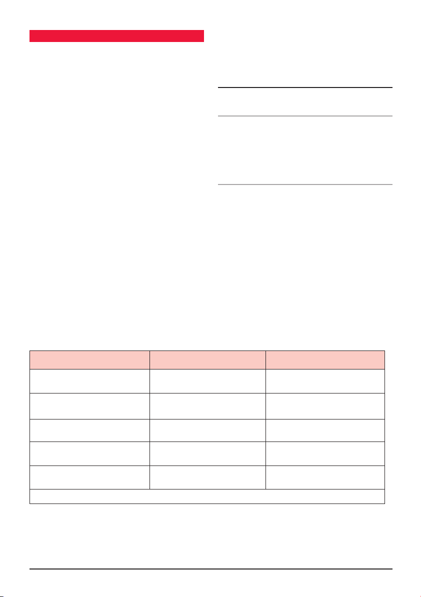
Type of disc Recorded material Size of disc
DVD
VCD
MP3/WMA
MPEG4*/DIVX*
CD
Sound and moving
pictures
Sound and moving
pictures
Sound only 12 cm
Sound and moving
pictures
Sound and still pictures 12 cm
NOTE: The unit is compatible with DVD, DVD +/-R, VCD 1.0/2.0/3.0, SVCD, CD, CD-R, CD-RW and JPEG
G D 96 00 S ER I E S I N ST RU C TI ON MA NUA L PA GE 3
12 cm
12 cm
12 cm
Page 4
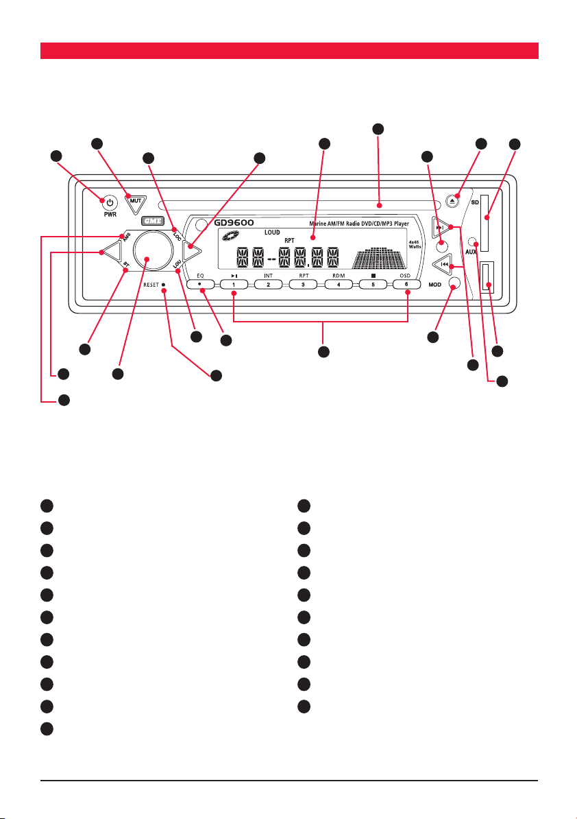
CO NT r Ol lO C aTi O NS
17
5
1
8 10
16
6
12
21
9
3
13
1
Power On/Off
2
Volume Control
3
Select
4
Loudness
5
Mute
6
Clock/Time Selector
7
Mode Switch
8
LOC/DX Selector
9
Stereo/Mono
10
Band Selector
11
Tuning/Selecting Tracks
2
4
14
15
20
12
Eject
13
Auto Music Search
14
EQ settings (Flat, Classic, Rock + POP)
15
Reset Button
16
LCD Display
17
CD Slot
18
Auxiliary Input
19
USB Input
20
Preset memory Keys and CD/MP3 functions.
21
SD Card Input
7
19
11
18
PA GE 4 I N ST RU C TI ON MA NUA L G D 96 00 S ER I E S
Page 5
iN STall aT iON
INSTALLATION PRECAUTIONS
If you are connecting your GD9600 for the first time or have
just reconnected your boat battery and you are experiencing
problems with the unit’s operation, we suggest you try
resetting the unit. The reset button is located under the
volume face panel. Gently press the reset button with a
paper clip or similar object.
Reset Button
The preset station memories and clock time are retained
only while the yellow ‘Memory 12 V+’ lead is connected
(see Electrical Wiring section). If the battery is disconnected
or switched off at the master switch, or the unit is removed
from the vessel, the station memories will be lost and the
clock will need to be reset.
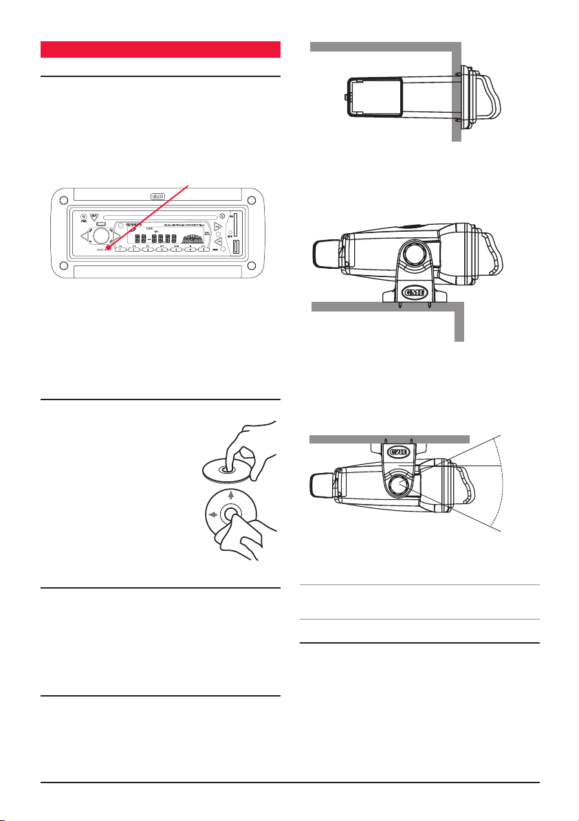
HANDLING COMPACT DISCS
• HandletheCD/DVDbyit’sedge,avoidtouchingthe
disc surface.
• Storeyourdiscsawayfromdirect
sunlight or heat sources. Keeping
the disc in it’s original case will
help to avoid damage.
• Cleanthediscwithasoftcloth
from the centre to the outer edge,
(see diagram) rather than in a
circular motion. Do not use solvents.
GD9620 Flush Mounted
GD9640 On-Dash Mounted
GD9640 Overhead Mounted
30
30
o
o
MOISTURE CONDENSATION
Your GD9600 uses optical laser technology. Occasionally
damp or humid conditions may cause condensation to
appear on the lenses inside the unit. Should this occur, the
unit might not operate correctly. Simply eject the disc and
leave the unit turned on for a while until the
moisture evaporates.
LOCATION
The GD9600 is available in a range of mounting
configurations to enable it to be installed in the most
convenient position. GME recommends that the unit should
be mounted in a position that is free from direct sunlight
and excessive vibration.
G D 96 00 S ER I E S I N ST RU C TI ON MA NUA L PA GE 5
Note. The GD9600 should not be mounted at angles
greater than 30° above or below the horizontal.
FLUSH MOUNTING - GD9620
The GD9620 can be neatly flush mounted into a panel or
bulkhead so that just the controls and the protective cover
are visible.
Using the template provided, select a suitable location on a
panel or bulkhead. Examine behind the panel to determine
the best method of support. If the thickness of the panel is
not sufficient to support the unit, it will be necessary to use
the strap supplied (see following diagrams).
Page 6
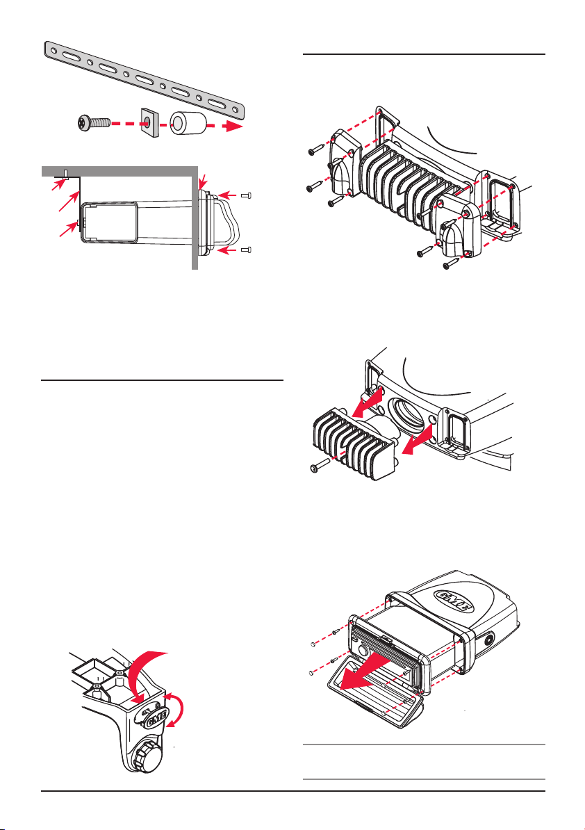
Flush Mount
S
upport Strap
R
ear centre Screw with Spacers
Rubber gasket
S
Screw
S
trap
crew
S
crew
Screw
* Use the rubber mounting gasket supplied. Place the gasket
between the plastic housing and the mounting surface. This will
improve the contact between the mounting surface and
stereo housing.
BRACKET MOUNTING - GD9640
1. Attach the GD9640 to the mounting bracket using the
two gimbal knobs.
2. Temporarily position the GD9640 in the desired location
and roughly mark the location of the bracket edges.
Now, remove the unit from the bracket and reposition
the bracket at the desired location to mark the
mounting hole positions.
3. Screw or bolt the bracket into position. The mounting
method will depend on the material to which the
bracket is being attached.
4. Refit the GD9640 into the bracket and adjust to the
desired angle before tightening the gimbal knobs.
5. Complete the antenna lead and electrical wiring
as described later.
For overhead mounting, the GME logos on the side of
each bracket can be rotated as shown right.
FLUSH MOUNTING - GD9640
Although the GD9640 is a bracket mounted unit, it can be
flush mounted by following the disassembly
instructions below.
1. Remove the 4 screws from each cable clamp
panel at rear.
2. Remove the screw from the centre of the heat
dissipater and remove.
3. Remove the 4 screw caps and 4 screws from the front
case and slide the unit out completely.
Your GD9640 can now be flush mounted. Replacement
screw caps have been provided to cover the exposed
screw heads.
Press from
back
Turn
* Note rubber mounting gasket not supplied with
GD9640 unit.
PA GE 6 I N ST RU C TI ON MA NUA L G D 96 00 S ER I E S
Page 7

REMOVING THE CLEAR COVER
If your GD9600 will be mounted in a dry protected location
away from the possibility of water ingress, the front clear
cover can be permanently removed.
3.
Connect the BLACK wire to the battery’s negative
terminal
or to the common negative bus in the electrical
system.
NEG
1. Remove the 4 screws from the top and bottom inside
edge of the mount frame as shown above. Remove
top latch assembly and clear cover.
Screw Caps
Fill Strips
S
crew Caps
2. Fit replacement fill strips as supplied into top and
bottom frame edges.
3. Mount your unit into the bulkhead. Use the screw caps
supplied to cover screw heads.
ELECTRICAL WIRING
DC Connections
Caution:
The GD9600 is designed for vessels with a 12 Volt
negative ground electrical system only!
Referring to the wiring diagram below:
1. Connect the Yellow wire directly to the positive terminal
of the vessel’s battery, or to a point that has +12 Volts
available at all times. This lead maintains the memories
within the GD9600 and is the main power source for
the unit.
2. Connect the RED wire to the vessels +12 V supply via
an appropriate isolating switch or circuit breaker. This
lead enables the radio to be switched ON and OFF.
Alternatively, this wire can be connected directly to the
battery’s positive terminal and the GD9600 switched
ON and OFF using it’s own controls.
YELLOW
RED
Important: Your GD9600 is able to maintain it’s
memories when it is switched off using the PWR button by
drawing power directly from your battery via the YELLOW
‘MEMORY 12 V+’ lead. Although the memory backup
current is very small (about 20 mA) it may eventually
discharge your battery if left connected indefinitely. The
time taken to completely discharge your battery could vary
depending on its Amp-hour rating and battery condition.
If you do not run your boat’s motor regularly or your battery
is not kept charged between outings (e.g. Solar or wind
charger), we recommend you disconnect the YELLOW lead
each time you secure or trail your boat. This is easily done
by connecting the YELLOW ‘MEMORY 12 V+’ lead via a
Master switch, which can be switched off after each outing.
This will mean you will lose all your preset station memories
and clock settings.
The blue wire on the wiring loom supplies 12 Volts when the
GD9600 is switched on and can be used to turn on an external
device, like the GME GA9800 marine amplifier, or enable the
back light on the GME RCU9200 wired remote
15 AMP
0.5 AMP
BLACK
BLUE
.
G D 96 00 S ER I E S I N ST RU C TI ON MA NUA L PA GE 7
Page 8

Caution: The GD9600 is a four-speaker system that
TE
requires 2 separate wires for each speaker.
A range of GME speakers are available from your local
GME retailer.
Speaker Connections
When connecting the speakers, observe the correct polarity
as shown in the diagram below. Incorrect polarity will result
in a reduction of bass response and stereo effect. The use
of speakers with an impendance of less than 4 Ohms is not
recommended, as they will cause excessive loading of the
GD9600’s output circuit and may result with the
radio overheating.
Left Front
Right Front
+ +
--
Left Rear
+
+
Right Rear
- -
REAR LEFT - GREEN/BLACK
REAR LEFT + GREEN
FRONT LEFT - WHITE/BLACK
AUX2
IN
BROWN
YELLOW: VIDEO IN
BLACK
RED: AUDIO IN R
WHITE: AUDIO IN L
BLACK
BLACK: DIGITAL COAXIAL AUDIO OUT
GREY
RED: AUDIO OUT REAR R
WHITE: AUDIO OUT REAR L
BROWN
RED: AUDIO OUT FRONT R
WHITE: AUDIO OUT FRONT L
BLACK
YELLOW: VIDEO OUT
DVD
OUT
FRONT RIGHT - GREY/BLACK
FRONT LEFT + WHITE
FRONT RIGHT + GREY
ANTENNA CONNECTOR
REAR RIGHT + PURPLE
REAR RIGHT - PURPLE/BLACK
BLACK
WIRED REMO
CONNECTION
WHITE
iPOD INPUT
VIA OPTIONAL LEAD
Connect all four speakers as shown in the previous diagram.
Adjust the Fader control for the required front/rear balance.
If you wish to connect only two speakers, connect these to
the Rear speaker wires. The remaining speaker wires should
be insulated to ensure they cannot short circuit together or
to the vessel’s 12 Volt or negative electrical Bus. If using only
two speakers, adjust the Fader control to the rear speakers.
Antenna Connections
Connect an AM/FM marine antenna to the antenna
socket which extends from the rear of the GD9600. For
information on a suitable antenna, contact your nearest
GME branch or marine retailer.
Wired Remote Control
The GD9600 has 1 additional fly lead at the rear enabling
a GME wired remote (RCU9200) to be connected. One or
more additional 5 meter leads (LEO24) can also be inserted
if required up to a maximum of 15 meters.
iPod® Connectivity
The GD9600 has a 2nd fly lead which, when connected with
an LEO23 (optional 1.1 meter lead), enables an iPod® to
be connected directly to the stereo. Limited functions of the
iPod® can be accessed via the GD9600, including the
selection of albums and songs. Access to displaying the
iPod® library on the GD9600 is not available however the
iPod library and all functions can be viewed on the iPod.
Reset Button
When the installation is complete, press the Reset
button on th face using a paper clip or similar object (see
‘INSTALLATION PRECAUTIONS’ on page 4). This will ensure
the GD9600 is ready to operate for the first time. If at any
time the controls do not seem to work (after replacing the
vessel’s battery for example), press the Reset button to
reset the microcomputer inside the GD9600.
FUSE REPLACEMENT
If any of the fuses blow, replace them with a standard
30 mm 3 AG type of the same rating, if the fuse blows a
second time contact your retailer.
The following fuse ratings are used:
-Yellow ‘Memory 12 V +’ lead: 15 Amp.
-Red ‘Ignition Switch ACC’ lead: 0.5 Amp.
PA GE 8 I N ST RU C TI ON MA NUA L G D 96 00 S ER I E S
Page 9

Op E r aTi O N
GENERAL FUNCTIONS
1
Power ON/OFF
To turn the GD9600 ON, press the PWR Button. The unit
will resume the mode and settings that were selected when
last turned OFF.
While the GD9600 is switched on, briefly press the power
button to change the brightness of the back lighting. There
are three levels of back lighting available.
To turn the GD9600 OFF, press and hold the PWR button
again. Note that when the GD9600 is turned OFF the clock
is displayed without the backlight.
2
Audio/Volume Control
The Volume, Bass, Treble, Balance and Fader controls are
selected electronically. The default setting is the
Volume Control.
To select an alternative control, press the SEL button
until the desired function is displayed on the LCD. Each
press cycles to the next function in sequence. Adjustment of
the selected control function is made using the large
rotary knob .
4
Loudness
2
Pressing the LOU button will provide a low frequency
(bass lift) boost to the audio output. To indicate selection
a ‘LOUD’ flag will be illuminated on the LCD. Pressing the
LOU button again will de-select the loudness function.
5
Mute
Pressing the MUT button will temporarily silence the
audio output. A flashing ‘MUTE’ is displayed on the LCD to
indicate the GD9600 has been muted. Pressing the MUT
button again will restore the previously selected audio level.
6
Clock
To display the current time, briefly press the clock button.
After 5 seconds the display will automatically return to it’s
original status. The time is shown in 12 or 24 hour format.
While the clock is displayed, press and hold the clock
button for about 1 second to adjust the time. The Hours
will flash. Rotate the volume control left or right to set the
hours. Briefly press the clock button again. The minutes
will flash. Rotate the volume control left or right to set the
minutes. Press the Clock button again to exit the
setting mode.
3
7
Mode
Pressing the MOD button will select the GD9600 operating
mode. TUNER, CD or AUX modes are sequentially selected
as MOD is pressed. If a USB MEMORY STICK OR SD CARD
IS INSERTED, ‘USB’ OR ‘CARD’ will also appear in the
the mode list. When the GD9600 is switched ON it will
automatically return to the modeit was in when
switched OFF.
8
Local/Distance Control (RADIO mode only)
Pressing the LOC button selects an internal attenuator
which will help to reduce the interference and distortion
often associated with very strong local radio transmissions.
A ‘LOC ON’ or ‘LOC OFF’ message is briefly displayed on
the LCD to indicate selection or deselection of the Local
Distance Control.
9
Stereo/Mono Selector
Pressing the ST button while on the FM Band, selects either
mono or stereo reception. The unit will momentarily display
‘MONO’ or ‘STEREO’ when toggling the ST button. The ST
flag is displayed when the GD9600 is in the stereo mode.
Selecting MONO improves reception when FM signals are
weak or noisy, by disabling stereo detection.
Select stereo for normal listening on FM radio bands, a
symbol is displayed when stereo signals are
being received.
RADIO OPERATION
Country Selection
When power is first applied, the GD9600 will default to the
European frequency bands. To toggle between European
and USA band sets:
1. With the radio on, press and hold the memory ‘3’ key
AND press the power key.
2. The radio will display ‘Goodbye’ and switch off.
3. Switch the radio ON again using the power key. USA
or Europe will be momentarily displayed to indicate the
selected band.
NOTE: If all power is disconnected from the GD9600,
the unit defaults to European frequency bands
when reconnected.
NOTE: The differences between bands is listed in the
specifications at the rear of the manual.
G D 96 00 S ER I E S I N ST RU C TI ON MA NUA L PA GE 9
Page 10

10
Band Selector
To select the radio band (AM1, AM2, FM1, FM2 or FM3)
sequentially press the BND button until the required band
is selected.
11
Tuning/Selecting Tracks/Chapters
Manual Tuning
To tune the radio manually, momentarily press the
or
button to select the desired frequency. Each press will
step the frequency by 50 kHz.
Automatic Tuning (Seek)
Press and hold either the
or buttons for 3 seconds.
The GD9600 will stop seeking when a strong, clear station
is detected.
12
Storing of Stations in Memory
Once the desired station has been selected, press and hold
one of the six pre-set station memory locations on the front
panel for 3 seconds. The corresponding button number will
appear on the LCD indicating that the selected station is
now programmed into the GD9600 memory.
13
Auto Programming of Radio Stations (AMS)
Select the required band
Press and hold the AMS button for 3 seconds; The GD9600
will now commence searching the band for radio stations.
As each station is located it is automatically stored in the
next available pre-set memory location. The new stations
will replace any stations previously stored in that band.
The scanning will continue untill all pre-set memory
locations are filled in each band.
Manually Selecting the Pre-Set Station Memories
Briefly press the desired station memory 1 - 6. The GD9600
will jump immediately to that station and the memory
number will appear on the LCD.
14
Preset Equaliser (P-EQ)
The GD9600 has four preset Graphic Equaliser settings to
enhance your audio listing pleasure. To select the P-EQ
14
mode, press the EQ
button sequentially to select and
display either FLAT, CLASSIC ROCK or POP modes.
Note: the TREBLE and BASS audio settings cannot be
adjusted when the P-EQ mode is selected.
CD/MP3/DVD OPERATION
Warning: Do not insert discs containing anything other
than CD, DVD or MP3 files into the disc slot. The CD/DVD
mechanism contains precision laser components which
could easily be damaged by inserting foreign objects.
Important: Because of the wide dynamic range offered
by CD/DVD systems, the difference in volume level between
very soft sounds and very loud sounds can be quite high.
For this reason we recommend that you avoid turning the
volume level up to loud when listening to very soft music or
tracks with no audio level, otherwise a sudden change to
very loud music could damage your speakers.
Inserting the CD/DVD
Remove the CD/DVD from it’s case and insert the disc, label
up, into the front panel aperture. The CD/DVD mechanism
will automatically draw the disc into the player and start
playing track 1 or chapter 1 if it is a DVD.
A disc symbol
is displayed on the LCD whenever
there is a CD/DVD in the player. The symbol will simulate
rotation whenever the disc is playing.
12
Ejecting a CD/DVD
Press the EJECT button
to stop the CD/DVD playing and
automatically eject the disc.
11
Fast Forward/Reverse
To advance through the present track or chapter at high
speed, press and hold the
button. The elapsed playing
time will be displayed and will advance rapidly. Release the
button to continue playing at the normal speed.
To reverse through the present track at high speed, press
and hold the
button. The elapsed time on the display
will decrease rapidly. Release the button to continue
playing the present track at the normal speed.
Stop
Press the STOP button, (numeric button #5 on the
front panel).
To return to the normal play mode press PLAY, (numeric
button #1 or
11
Step to the Next Track or DVD Chapter
To step immediately to the next track, press the
on the remote control).
button
once. The next selected track will begin playing, press the
button to advance to the start of successive tracks.
PA GE 10 I N ST RU C TI ON MA NUA L G D 96 00 S ER I E S
Page 11

To step immediately to the start of the track currently being
played, press the button once. The current track will
immediately restart. Press the button repeatedly to
locate the start of previous tracks.
11
Pause
To pause playing the CD/DVD, press the
button once.
The disc symbol on the LCD will stop rotating when the
pause function has been selected.
Press the button again to resume playing the CD/DVD.
Repeat Play
To continually play the current track or chapter, press the
RPT button (Numeric button #3 on the front panel). Press
once to repeat the current track. Press again to repeat
the current directory (mp3’s) or album (audio CD). Press
again to turn the repeat function OFF. A ‘RPT’ flag will be
illuminated on the LCD when in the repeat mode.
Random Play
To play tracks on the CD in a random order, press the RDM
button (Numeric button #4 on the front panel). A ‘RDM’ flag
will be illuminated on the LCD when in the random mode.
Press the RDM button again to return to the normal mode.
Note: the RDM function is not operational when
playing DVDs.
Intro-Scan
The intro-scan feature plays the first 10 seconds of each
track allowing you to identify the songs on the CD.
To select intro-scan press the INT button (Numeric button
#2 on the front panel), the LCD will display INT, track
number and elapsed time.
Press the INT button again to return to the normal mode.
Note: Intro – Scan does not operate in DVD, MP3 or
WMA formats.
OSD (On Screen Display)
Press the OSD button (Numeric button #6 on the front
panel) to display Track, Chapter, Elapsed Time and other
information on the monitor.
MP3 Functions
MP3 (MPEG-1 Layer 3) is a format for the compression of
audio files to approximately 8% of their original size. This
permits a large number of files to be stored on a CD-R,
CD-RW, SD Card or USB memory stick.
Unique Remote Control Functions
There are a number of functions on the GD9600 that are
only accessible through the remote control handset.
Zoom (DVD Mode only)
The GD9600 has 6 Zoom settings, to enter the Zoom
mode, press the ZOOM button on the remote control, the
sequentially move to either x2, x3, x4 or 1/2, 1/3 or Zoom
mode the cursor keys may be used to pan around
the picture.
Subtitles (DVD Mode only)
Press the SUBTITLE button on the remote control to
display subtitles.
Set Up
To enter the SET UP mode, Press the STOP button, then
press the SET UP button on the remote control.
Use the
S
/ keys to select SYSTEM SET UP,
ET UP, AUDIO SET UP, VIDEO SET UP or DIGITAL SET UP.
LANGUAGE
Then use the / / / keys to navigate around the
sub-menu to select and change operating parameters.
Multi Angle (DVD Mode only)
Press the ANGLE button on the remote control to view the
DVD content from a different angle.
Note: Not All DVDs support this feature.
Slow Motion (DVD Mode only)
Press the SLOW button on the remote control to slow the
DVD viewing speed. There are 6 speeds available, continue
pressing the SLOW button to access the different speeds.
PBC Title (DVD Mode only)
Press the PBC button to access the menu, then use the
/ / / keys to navigate around the screen and
select options.
Numeric Keys
In RADIO Mode – Press any one of the 1 to 6 NUMERIC
KEYS to select a pre-set radio station.
In the CD mode – Press any one of the NUMERIC KEYS to
select a track.
GOTO
The GOTO function allows the operator to select specific
tracks or chapters from the disc.
Press the GOTO button on the remote control; use the
/ keys to move the highlighted cursor to the required
field, then using the Numeric keypad modify the selected
field to the track or chapter required, press ENTER to
confirm selection.
G D 96 00 S ER I E S I N ST RU C TI ON MA NUA L PA GE 1 1
Page 12

Precautions for CD-R and CD-RW Discs
The GD9600 will not play a CD/DVD that has not been
finalised, please refer to the instruction manual of the
software or the recorder you are using to write these CDs
for the finalisation process.
To ensure a more reliable playback, please follow GME
recommendations:
• UseCD-RWswithaspeedof1xto4xandwritewitha
speed of 1x to 2x.
• UseCD-Rswithaspeedof1xto8xandwritewitha
speed of 1x to 2x.
• DonotplayCD-RWsthathavebeenwrittentomore
than 5 times.
Note: If a disc contains audio CD data and MP3 files, the
GD9600 will only play which ever is first on the disc. If the
first track on the disc is an MP3 file, the unit will only play
the MP3 files from the disc, and will ignore all other files
and vice versa.
Precautions for MP3
The format of the disc must be ISO9660 level 1 or 2, or
Joliet or Romeo in the expansion format.
When naming an MP3 file, ensure the file extension is ‘.MP3’
The GD9600 will not recognise a non MP3 file even though
the name extension is ‘.MP3’.
Configuration Menu
Press and hold the SEL key to enter the configuration menu
then briefly press the SEL key to cycle through the available
configuration options. Rotate the Volume knob to change
the selected option. Press BND to exit the menu or simply
wait a few seconds for it to time-out.
Function Options Description
Volume Last, Default Set preset ON
volume level
AVOL Level 00 - 47 Set Preset Vol for
Default above
Clock On, Off Enables clock
on display whn
switched off
Clock format 12, 24 Sets 12 or 24 hr
clock display
au Xi l ia rY iN puT S & Ou T pu T S
To maximise the owner’s listening flexibility and pleasure
the GD9600 has several auxiliary inputs and outputs.
FRONT PANEL INPUTS
There are standard USB and SD Card inputs located on the
front panel.
USB
The USB Input accepts USB flash memory drives loaded
with MP3 files. Max USB memory size that can be used is
16GB. When using the USB input we recommend using the
USB adapter AD003 supplied as a standard accessory with
your GD9600. This allows the transparent front cover to be
fully closed to avoid any possibility of water ingress.
When the USB input is in use, ‘USB’ is added to the options
on the MOD button.
Note: The USB input is not designed to be connected
to the USB port of a external MP3 player. External MP3
players should be connected to the AUX input via an audio
interface cable.
SD Card
The SD card slot accepts SD and SDHC memory cards up
to 16 GB.
When the SD card slot is in use, ‘CARD’ is added to the
options on the MOD button.
Aux Input
The GD9600 has a 2.5 mm stereo jack low level (1 Volt
peak to peak) audio input socket on the front panel.
Owners may use this input for external audio sources that
they wish to play through the vessel’s stereo system.
GME offers a custom interface cable for a personel MP3
player connection; Part # LE68. When using this cable, it
is necessary to use the portable device functions to control
play.
CONNECTING AN iPod*
The GD9600 can be connected directly to an iPod via the
optional LE023 iPod interface lead. The interface lead
connects to the iPod fly lead at the rear of the GD9600 and
provides a direct connection to the interface socket on the
iPod. The cable is compatible with the current iPod Nano,
Classic, Touch and iPhone models.
When an iPod is connected the GD9600 displays IPOD.
Album and song selections can be made from the GD9600
or directly from the iPod itself. Any selections will be
displayed on the iPod screen.
PA GE 12 I N ST RU C TI ON MA NUA L G D 96 00 S ER I E S
Page 13

To make individual selections from the GD9600 controls
press the AMS button. ‘Menu’ is displayed on the GD9600.
During this time, press the AMS button to step back
through the iPod screen menus, rotate the Volume control
to highlight items on the iPod screen and press BND
to make a selection. To exit the GD9600’s iPod ‘Menu’
function press SEL or wait a few seconds and the menu will
time-out. Normal AMS, Volume and BND functions
will resume.
To select another song press
or to step forward or
back through the song list.
The iPod battery will be charged while it is connected to
the GD9600.
REAR OUTPUTS AND INPUTS
The GD9600 has Audio outputs plus Video inputs and
outputs. These inputs and outputs are clearly labelled and
colour coded, they are also identified in the wiring diagram
shown on page 8 of this manual.
rE M OT E C ON T rO l
A standard accessory with the GME GD9600 is a a wireless
remote control (RCW9600). The remote will permit the control
of all major GD9600 functions from a distance of up to
3 metres.
Ensure plastic battery protection tab is removed from the
handset before initial operation.
Simply point the remote handset at the GD9600 and select
the required option on the keypad.
REMOTE CONTROL FUNCTIONS
Cautions
The remote control handset is not waterproof and should
•
be
kept well away from both fresh and salt water at all
times.
• Theremotecontrolshouldnotbeleftindirectsunlight
for prolonged periods, excessive sunlight and heat
could cause damage to the keypad resulting in incorrect
operation or non function.
Bat t er y r ep l ace me n t
Should the working range of remote control handset
reduce, or functions fail to operate correctly. The battery
should be replaced:
1. Turn remote over, insert thumb nail between grooves
on the battery cover latch and slide to the right, pull
out the battery tray.
SET-UP
ZOOM
SEEK+
GOTO
4
Pause/Play
Mu
te
Menu Display
Su
btitle
Set-up
Angle
Slow-motion
Play
Zoom
Volume
Sound
Characteristics
Audio
Go To
Button
2. Replace the battery, (type CR 2025 or equivalent),
with the positive side facing upwards.
3. Slide the battery tray back into the handset.
Mode
Power
Band/System
Enter
Eject
Program
Playing
Re
peat Play
ndom Play
Ra
Tuning/
lecting
Se
tracks/FF/
Rewind
PBC Menu
On-screen
Display
mber but-
Nu
tons
BND
SYS
AMS
RPT
LOC
RDM
PBC
1
9 0
MODE
TITLE SUB-T
ENTER
ANGLE SLOW
ST
VOL+
PROG
SEEK-
SEL
OSD
VOL- AUDIO
2
3
657 8
10+
RCW9600
G D 96 00 S ER I E S I N ST RU C TI ON MA NUA L PA GE 1 3
Page 14

Op T iON al aCC ESS Ori ES
There are a number of high quality GME accessories
available to enhance your marine entertainment experience.
These accessories are available through your local GME
retailer, should you have any difficulty in obtaining any
GME accessory, please call or email your local GME Sales
Office (within Australia and New Zealand). Contact details
are listed on the back page of this manual.
International customers should also refer to the back page
for details of your local importer or visit:
www.gme.net.au
SPK001 and SPK002 speakers
• MarineSpeakers
• ComprehensiveRangeofMarineAntennas
• InterfacecableforMP3devices
• RCU9200-WiredRemoteControlforStereo
• LE024-WiredRemote5mExtensionCable
• LE023-iPod*ConnectivityLead1.1mLong
*iPod is a trademark of Apple Computer Inc., registered in the U.S.
and other countries.
From time to time GME may introduce new and additional
products to the range or discontinue existing accessories.
Details of any changes may be found at our website:
www.gme.net.au
LE023 iPod interface cable LE024 RCU Interface cable (5m)
SPK005 and SPK006 box speakers
SPK007 6 x 9 speaker RCU9200 wired remote LE68 AUX input cable
SPK008 wake board speaker
and SPK010 marine subwoofer
PA GE 14 I N ST RU C TI ON MA NUA L G D 96 00 S ER I E S
GA9800 - GME Marine Amplifier
AM/FM Antennas
Page 15

GD 960 0 t ro u Ble S h oo t in G G u iD e
SY M P TO M C A U S E SO L UT I ON
No Power. Vessel’s battery switch is not on. Check master switch if fitted.
One of the fuses is blown. Replace the damaged fuse with the
correct value.
Error messages displayed on LCD or
functions not operating.
Poor radio reception. Damaged or incorrect type of antenna. Check antenna and replace
CD/DVD cannot be loaded. There is already a CD in the player. Remove disc, then insert new disc.
Microprocessor lock up. Press Reset Button.
if necessary.
CD/DVD is upside down. Insert correct way up.
CD/DVD is damaged or dirty. Clean or try another disc.
CD/DVD has moisture on it. Dry disc and retry.
CD/DVD reader has moisture on lens. Leave player on for an hour or so
and retry.
Sp E Ci f iCaT i ON S*
FM RADIO
Frequency Range: 87.5 - 108 MHz (Eu./Aust./N.Z.)
87.5 - 107.9 MHz (U.S.A.)
Frequency Step: 50 kHz
Intermediate Frequency: 10.7 MHz
Sensitivity (30 dB S/N): 13 dBuV (typical)
Channel Separation: >22 dB
Station Memories: 18
AM RADIO
Frequency Range: 522 - 1620 MHz (Eu./Aust./N.Z.)
530 - 1710 MHz (U.S.A.)
Frequency Step: 9 kHz (Eu./Aust./N.Z.)
10 kHz (U.S.A.)
Intermediate Frequency: 455 kHz
Sensitivity (20 dB S/N): 25 dBuV
Station Memories: 12
COMPACT DISC MECHANISM
Mechanism: Auto Loading
Signal to Noise Ratio: 65 dB
Format: 8 times oversampling
Environmental: Anti-vibration/Anti-shock
AUDIO AMPLIFIER
Audio Output: (4 channels x 45 W Peak =
180 W Peak) @ 10% THD.
Speaker Impedance: 4 Ohm
Frequency Response: 40 Hz - 18 kHz
Bass Adjustment Range: +/- 8 dB @ 100 kHz
Treble Adjustment
Range: +/- 10 dB @ 10 kHz
DVD PLAYER
Aspect Ratio: 4:3 Letter box
4:3 Pan Scan or 16:9
Video Output Level: 1.00 Volt Peak to Peak
( 75 Ohms Impedance )
Horizontal Resolution: 500
Video System: Auto/PAL/NTSC
GENERAL
DC Supply Input: 11 – 16 Volts Negative Ground
Memory Back-up: External Back-up Memory Wire
Back-up Current: Approximately 20 mA
Overall Size: 232 mm (W) x 97 mm (H) x
200 mm (D)
Weight: Approx 1.75 kg
Supply Current: 7 Ampere (max.)
*All specifications are typical and subject to change without notice or obligation.
G D 96 00 S ER I E S I N ST RU C TI ON MA NUA L PA GE 1 5
Page 16

WAR R ANT Y
GME limit this warranty to the original purchaser of
the equipment.
GME warrant this product to be free from defects in
material and workmanship for a period of twelve (12)
months from the date of purchase from their
authorised retailer.
Should the product require servicing during this period, all
labour and parts used to effect repairs will be supplied free
of charge. GME reserve the right to determine whether
damage has been occasioned by accident, misuse or
improper installation whereby the warranty would be
void, including:
Equipment which has been damaged due to:
(a) Incorrect or reverse polarity connection to a battery or
power supply.
(b) Connection to incorrect supply voltage.
(c) Effects of water or moisture penetration.
(d) Non-factory modifications.
(e) Use of incorrect replacement fuse.
Procedure to be followed by claimant: In the event of a
defect occurring during the twelve (12) month warranty
period, the original purchaser may return the defective unit
along with suitable proof of purchase date (i.e. receipt,
docket, credit card slip etc.) and a full description of the
defect to any authorised retailer.
All freight charges incurred for transportation by the retailer
or GME are the purchaser’s responsibility.
The retailer will forward the unit to the closest authorised
GME Service Depot in your particular area.
GM E A F TER SA LE S S E RV I CE
Your GME GD9600 is especially designed for the
environment encountered in marine installations. The use of
all solid state circuitry, careful design and rigorous testing,
result in high reliability. Should failure occur however, GME
maintain a fully equipped service facility and spare parts
stock to meet the customer’s requirements long after expiry
of the warranty period.
Warning: Extreme care should be taken when connecting
any external device to your GD9600 rear inputs or outputs.
GME strongly recommends that all connections should be
carried out by a suitably qualified technician.
Part Number: 310507 Drawing Number: 45283-3
PA GE 1 6 INSTRUCTIO N M AN UA L GD9600 SE R IE S
Page 17

68 mm
GD9 6 0 0 se r i e s f lu s h m o u nt c ut tin G t e m p l at e
197 mm
Outer edge of unit
Inner edge of unit - Cut out
Part Number: 310390 Drawing Number: 43686-3
 Loading...