

Global Mainstream Dynamic Energy Technology Ltd.
User Manual
User Manual
1-Phase PV+ Storage Hybrid Inverter
—For Powervortex 5200TL——
- 1 -

Global Mainstream Dynamic Energy Technology Ltd.
User Manual
Content
Prelude ............................................................................................................................................................ 4
Read this user manual before you start ..................................................................................................... 5
1. Safety ........................................................................................................................................................... 6
1.1 How to Use This Manual ........................................................................................................................... 6
1.2 Safety Rules ................................................................................................................................................. 6
1.3 Warning Notices Affixed to the Device ............................................................................................... 7
1.4 Important Safety Information ................................................................................................................. 7
1.5 Disposal ........................................................................................................................................................ 8
1.6 Exclusion of Liability ................................................................................................................................... 8
2. Description ................................................................................................................................................. 9
2.1 General System Description ................................................................................................................... 9
2.2 Device Physical Description ................................................................................................................. 11
2.3 Outside Dimension of the Device ....................................................................................................... 12
2.4 Technical Data ........................................................................................................................................ 12
3. Installation ................................................................................................................................................ 13
3.1 Operation Sequence ............................................................................................................................. 13
3.2 Unpacking ................................................................................................................................................. 15
3.2.1 Unpacking the Device ................................................................................................................... 15
3.2.2 Packing List ........................................................................................................................................ 15
3.2.3 Identifying the Inverter ................................................................................................................... 17
3.3 Mounting ................................................................................................................................................... 17
3.3.1 Choosing a mounting location ................................................................................................... 17
3.3.2 Mounting the Hybrid Inverter ....................................................................................................... 18
3.4 Electrical Connection ............................................................................................................................ 19
3.4.1 Connectors ....................................................................................................................................... 19
3.4.2 DC Connection ............................................................................................................................... 20
3.4.3 AC Connection................................................................................................................................ 20
3.4.4 Communication Interface Port ................................................................................................... 21
4. System Settings ........................................................................................................................................ 22
4.1 LCD .............................................................................................................................................................. 22
- 2 -

Global Mainstream Dynamic Energy Technology Ltd.
User Manual
4.1.1 LCD Interface ................................................................................................................................... 22
4.1.2 LCD Indication Lights ...................................................................................................................... 23
4.1.3 LCD Display Definition .................................................................................................................... 23
4.1.4 LCD Display Menu Definition ........................................................................................................ 24
4.1.5 LCD Setting Menu ........................................................................................................................... 24
4.2 WiFi .............................................................................................................................................................. 36
4.2.1WiFi Function ...................................................................................................................................... 36
4.2.2 WiFi Configuration ........................................................................................................................... 37
5 Troubleshooting ........................................................................................................................................ 40
5.1 Safety during Troubleshooting ............................................................................................................. 40
5.2 Faults ........................................................................................................................................................... 40
5.3 Fault Messages and Actions List .......................................................................................................... 40
5.4 Fault Acknowledgement ...................................................................................................................... 43
5.5 Technical Service .................................................................................................................................... 43
- 3 -

Global Mainstream Dynamic Energy Technology Ltd.
User Manual
Published by
Global Mainstream Dynamic Energy Technology Ltd. (GMDE)
3rd Floor, Building 7, Eureka City Industrial Park, No.333 Zhujian Rd,
Minhang District, Shanghai, China.
Tel: +86 21 60710806
service@global-mde.com
Legal Disclaimer
All information in this documentation has been compiled
and checked with most care. Despite of this, errors or
deviations cannot be completely excluded. We assume
no liability therefore.
User is encouraged to check updated version at
http://www.global-mde.com/
Copyright
The details of this documentation are the property of GMDE.
Using and publicizing this documentation, even if only in
parts require the written consent of GMDE
Prelude
- 4 -

Global Mainstream Dynamic Energy Technology Ltd.
User Manual
Read this user manual before you start
Thank you for purchasing our products, this hybrid inverter is highly reliable and efficient due to
its convenient design and excellent quality. This Powervortex 4600 / 5200TL device is IP20 what is
rated for dusty or humid environments and is only suitable for indoor installation.
If you are reading the electronic version of the manual, please note that you can click the
content to find information you want quickly. All the characters which contain underline are
clickable. A phrase named ‘Back to Top’ at the bottom of each chapter can help you back to
the first page rapidly.
Before using this device, please ensure that you have read this manual including installation
and safety operation carefully.
If you have any difficulties during installation or operation, please refer to this manual or send
email to service@global-mde.com,we will help to solve your problems as soon as possible.
- 5 -
Global Mainstream Dynamic Energy Technology Ltd.
User Manual
Danger
Death or severe personal injury will occur.
Warning
Death or severe personal injury may occur.
Caution
Personal injury or material damage may occur.
Electric Shock!
Do not open the device! Dangerous voltage may still be applied inside
the device even after it has been switched off.
High leakage current!
Make absolutely sure you establish connection to ground before
connecting the device to the supply circuit!
Health risk!
Health risk for persons with cardiac pacemakers, metallic implants or
hearing aids in the immediate vicinity of electrical equipment!
Risk of improper handling!
Personal injury by crushing, shearing, cutting or striking.
Cancellation of the operating license!
If the GMDE inverter is operated with a wrong country code, the electric
supply company may cancel the operating license.
Hot surface!
Surfaces of the housing can be hot! Risk of injury! Risk of burns.
The housing top and the heat sinks may have a surface temperature of
70°C.
1. Safety
1.1 How to Use This Manual
Please read the safety instructions in this manual first. Throughout the manual it is assumed that
the reader is familiar with AC and DC installations and knows the rules and regulations for
electrical equipment and for connecting it to the utility AC grid. It is especially important to be
familiar with the general safety rules for working with electrical equipment.
This manual is intended for qualified electricians.
1.2 Safety Rules
General introduction
These safety-related guidelines use the following warning notices to describe the various levels
of danger:
Explanations
- 6 -

Global Mainstream Dynamic Energy Technology Ltd.
User Manual
WARNING!
Inverter only to be opened by authorized personnel!
1.3 Warning Notices Affixed to the Device
1.4 Important Safety Information
The following operating and maintenance instructions must be read before installing, operating
or maintaining the inverter.
Before installation:
Check for damage on the device and package. If you are in doubt, please contact us or the
distributor before installing the device.
Before connecting the solar modules or battery packs with the product, please check the
voltages and make sure they are within the limits of the GMDE inverter specifications. Failure to
observe these specifications could void your warranty.
Installation:
Only trained and qualified personnel familiar with local electrical codes may work with the
electrical installations. For optimum safety, please follow the steps described in this manual.
Disconnecting the product:
Please refer to “Disconnecting for maintenance”. Note that, after disconnecting the hybrid
inverter from AC grid, PV panels and battery packs, wait at least 15 minutes before proceeding.
Operating the product:
Do not commission the device until the whole system complies with the application-specific
national rules and safety regulations.
The ambient conditions given in the product documentation must be observed.
The device manufacturer or installer is responsible for compliance with the limit values as
prescribed in the national regulations.
Only persons who are trained and qualified for the use and operation of this device may work
on the device.
Maintenance and modification:
Only authorized personnel are allowed to repair or modify the inverter. To ensure optimum
safety for user and environment, only the original spare parts available from your supplier should
be used.
Functional safety parameters:
Unauthorized changes of functional safety parameters may cause injury or accidents to people
or inverter. Additionally it will lead to the cancellation of all inverter operating approval
- 7 -

Global Mainstream Dynamic Energy Technology Ltd.
User Manual
Please dispose the package and replaced parts according to the rules
applicable in the country where the device is installed. Do not dispose the
GMDE inverter with normal domestic waste.
certificates.
1.5 Disposal
1.6 Exclusion of Liability
GMDE Technology Ltd. will not be liable for any direct, indirect or consequential damages,
losses, costs or losses including without restriction any economic losses of any kind, any loss or
damage to property, any personal injury, any damage or injury arising from or as a result of
misuse or abuse, or the incorrect installation, integration or operation of the product. We
disclaim any liability for direct or indirect damages due to:
1. Improper installation or commissioning,
2. Modifications, alterations or repair attempts,
3. Inappropriate use or operation,
4. Insufficient ventilation of the device,
5. Non-compliance with relevant safety standards or regulations,
6. Flood, lightning, overvoltage, storm, fire (acts of nature).
We do not assume any liability for an incorrectly set country code. We reserve the right to make
alterations that will improve the function of the device.
- 8 -
Global Mainstream Dynamic Energy Technology Ltd.
User Manual
2. Description
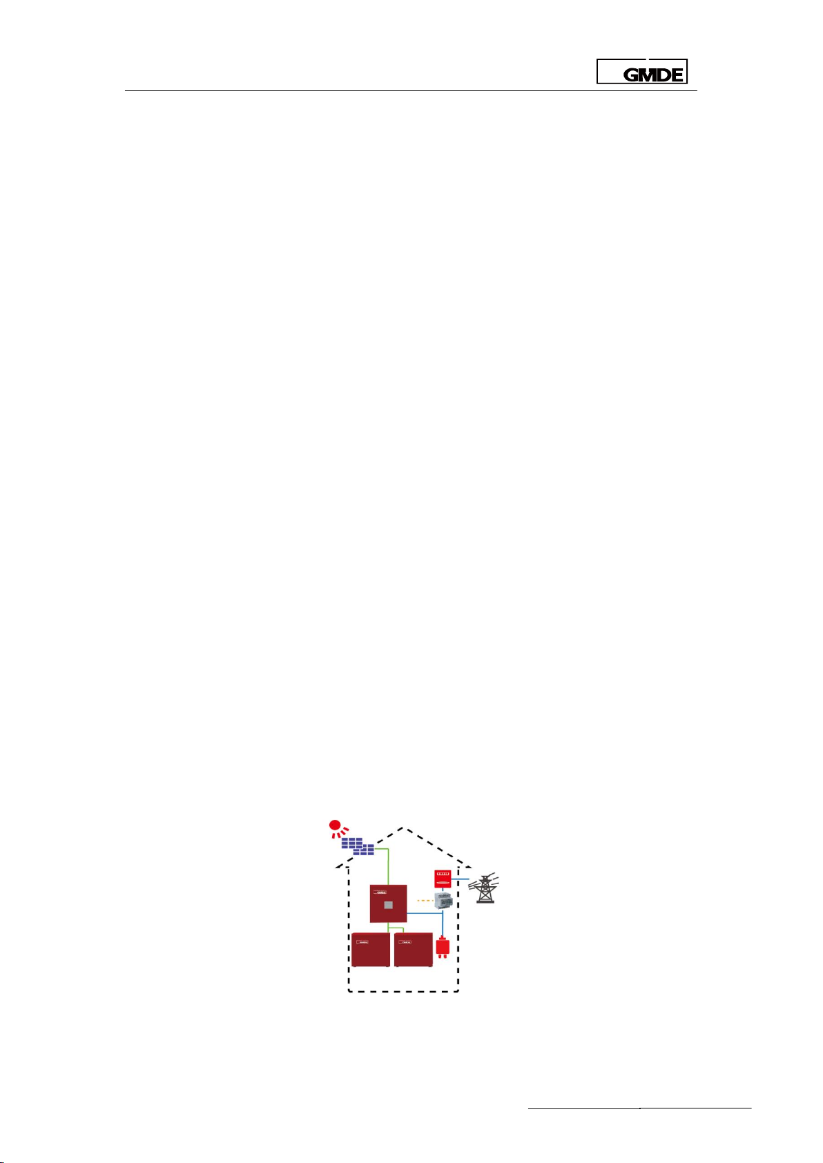
2.1 General System Description
GMDE Powervortex 4600/ 5200TL hybrid inverter is designed for new PV storage system
installation. The Solar battery hybrid system with Powervortex 4600/ 5200TL is consisted of 3
modules: Powervortex 4600/ 5200TL storage inverter, battery packs and meter.
Powervortex 4600/ 5200TL storage inverter
The storage inverter converts the DC power generated by PV modules into AC power. The
generated electricity from PV is used by the household loads, being charged into the battery
packs or being fed into the grid.
48V Lithium/Lead battery packs
Battery packs stores the energy generated from solar energy and increases self-use up to 70%.
Energy meter
Adopt the 1-phase bi-directional energy meter for communication, and hybrid inverter controls
when to charge/discharge according to the data from the meter.
Solution: Integrated Energy Management Solution
Through RS485 communication cable, the hybrid inverter communicates with the power meter
installed between the AC grid and load. With the power-related information sent from the
power meter, the hybrid inverter can automatically decide when to charge or discharge the
battery packs.
Note that:
With lithium batteries, an independent BMS is compulsory to maintain battery’s lifetime. Make
sure the Powervortex 4600/ 5200TL has integrated the BMS communication protocol.
The power meter used in this application must be recommended or confirmed by GMDE since
the integration of communication protocol between power meter and GMDE hybrid inverter is
required.
Figure 1 Solar battery hybrid system with Powervortex 4600 / 5200TL
- 9 -
Global Mainstream Dynamic Energy Technology Ltd.
User Manual
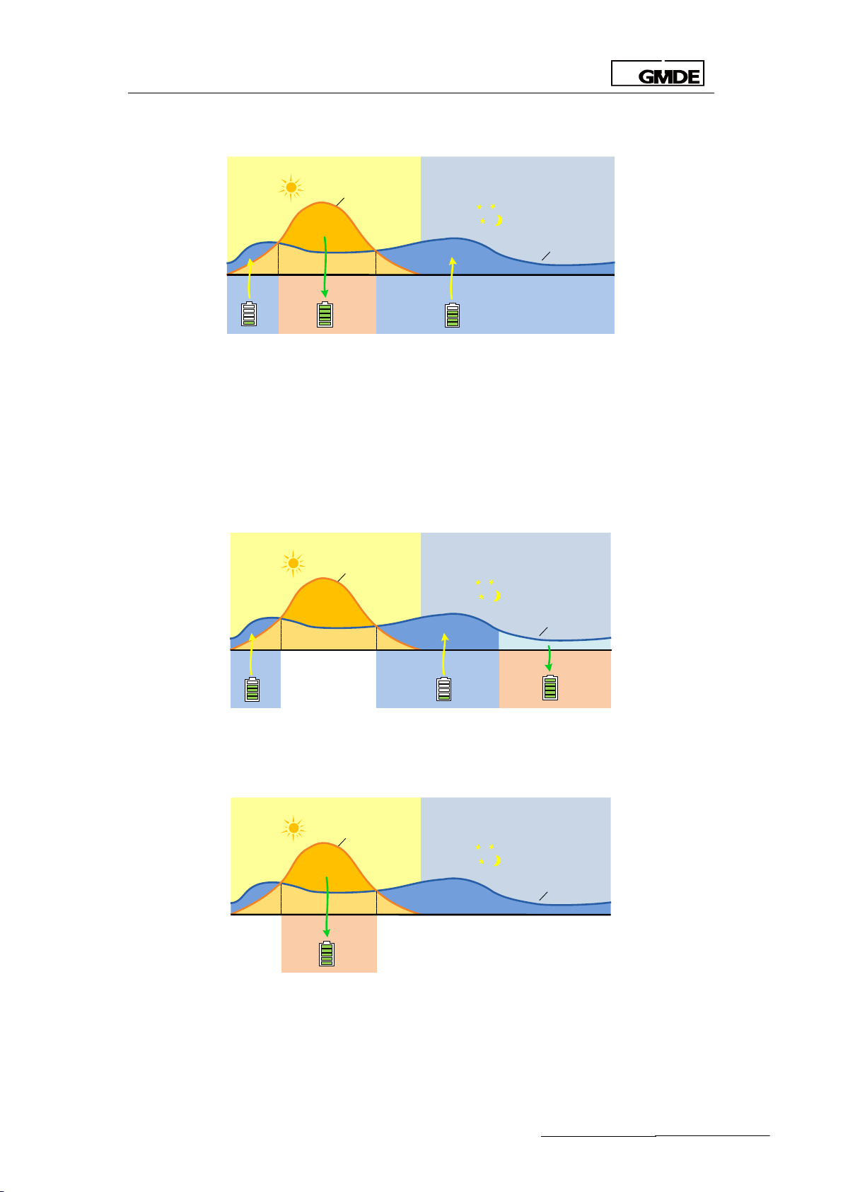
6AM 12AM 6PM
2AM
8AM 10AM 2PM 4PM
12PM8PM 10PM
4AM
PV Power Curve
Load Curve
6AM 12AM 6PM
2AM
8AM 10AM 2PM 4PM
12PM8PM 10PM
4AM
PV Power Curve
Load Curve
6AM 12AM 6PM
2AM
8AM 10AM 2PM 4PM
12PM8PM 10PM
4AM
PV Power Curve
Load Curve
The hybrid inverter has 2 options of operation mode:
1. Self-use Mode
If there is enough sunshine, energy generated by PV supplies the load first and then charges
battery packs; if the load power is covered and battery is full charged, surplus energy will be fed
into the public grid to win the FiT tariff;
If there is no sufficient PV energy, the system first discharges the battery pack; if PV power plus
battery discharging power is smaller than the load power, then the grid co-supply energy to the
load together with the system.
2. Time of Use Mode (Peak Shaving)
The system charges the battery packs at off-peak time (pre-set charging time); discharge the
battery packs at peak time (pre-set discharging time).
When the grid is failed or abnormal
The Powervortex 4600/ 5200TL hybrid inverter has integrated backup function.
Note: Maximum Charging current, Maximum Discharging current, Discharging Stop Voltage
and Charging Stop Voltage should be set before commissioning to maintain battery’s lifetime.
- 10 -
Global Mainstream Dynamic Energy Technology Ltd.
User Manual
PV1 PV2
GRID
LOAD
WIFI
CANRS485Ethernet
BAT
SETDRED
1
2 3
4
5
6
These parameters are set in LCD screen.
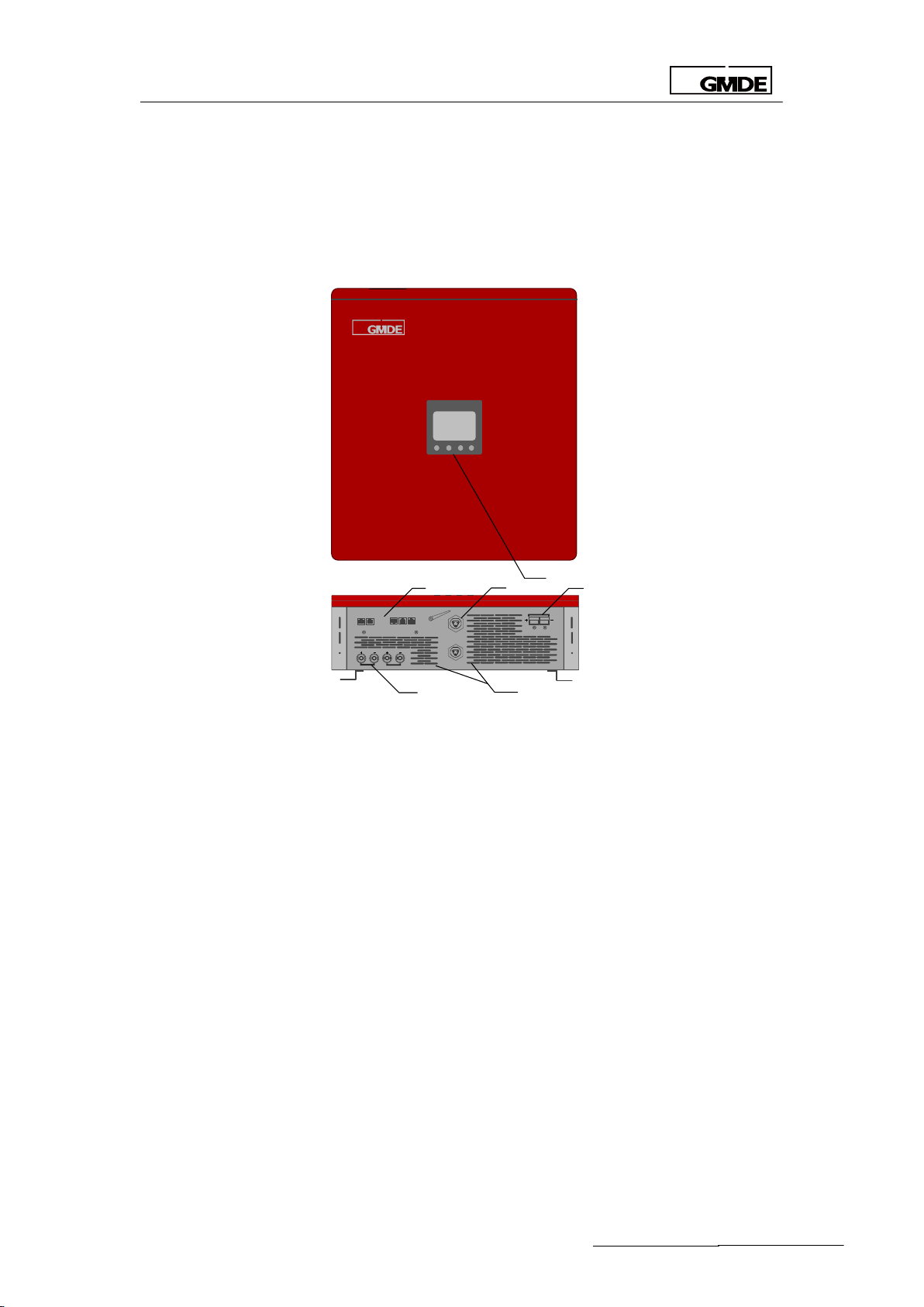
2.2 Device Physical Description
The GMDE Hybrid inverter is a single-phase inverter, which could help customers to reduce their
electricity expense by optimizing use of PV and battery energy or for peak shaving.
Figure 2 GMDE Powervortex 4600/ 5200TL
(1) 320x240 pixels display screen, on which the operation related information can be displayed.
(2) The GMDE hybrid inverter provides multiple communication choices: Ethernet (Reserved) /
RS485 / CAN (Reserved).
(3) AC output connector to the grid and the important load, which connect to AC grid and
important load. (Rated conductor size: Ø 6 mm2).
(4) One pair of battery input connectors to connect with battery packs.
(5) 2 pairs of PV-input terminals, each input pair consists of positive and negative terminals.
(6) Heat is dissipated by the heat sink and fan equipped at the bottom of this device.
- 11 -

Global Mainstream Dynamic Energy Technology Ltd.
User Manual
PV1 PV2
GRID
LOAD
WIFI
CANRS485Ethernet
BAT
SETDRED
550
610
192
MODEL LIST
Powervortex4600TL
Powervortex5200TL
INPUT PV
PMAX PV [W]
4600
5200
VMAX PV [Vdc]
580
580
ISC PV [A]
2*18.8
2*18.8
MPP Voltage Range VMPP[Vdc]
125-550
125-550
Max. Input Current [A]
2*15
2*15
MPP Full Power Voltage Range [Vdc]
153-550
173-550
Input DC Operating Voltage Range [Vdc]
125-550
125-550
Start PV Voltage [Vdc]
125
125
Stop PV Voltage [Vdc] (PCE Shutdown)
105
105
Overvoltage Category (OVC)
OVC II
OVC II
INPUT BAT
VMAX BATTERY [Vdc]
60
60
VMIN BATTERY [Vdc]
40
40
Maximum Charging Power [W]
3000
3000
Maximum Discharging Power [W]
3840
3840
Maximum Charging Current [A]
60
60
Maximum Discharging Current [A]
80
80
2.3 Outside Dimension of the Device
2.4 Technical Data
Figure 3 Outside dimension of Powervortex 4600/ 5200TL
- 12 -
Global Mainstream Dynamic Energy Technology Ltd.
User Manual
OUTPUT GRID
Rated Output Voltage Ur [Vac]
1N~ 230
1N~ 230
Operating Voltage Adjustable Range Un
[Vac]
180-264
180-264
Rated Output Frequency FNETZ [Hz]
50
50
Rated Output Power PE [W]
4400
5000
Max. Output Power PEmax [W]
4400
5000
Max. Apparent power SEmax [VA]
4400
5000
Rated Output Current Ir [A]
19.1
21.7
Max. Output Current Imax [A]
21.0
23.8
Power Factor cosφ [λ]
[-0.8,+0.8] adjustable
[-0.8,+0.8] adjustable
Standby Power Consumption [W]
< 15
< 15
Night Power Consumption [W]
< 0.5
< 0.5
THD [V / I] (100% full power)
< 3%
< 3%
Acoustic Noise [dB]
< 55
< 55
Overvoltage Category (OVC)
OVC III
OVC III
SYSTEM
Type of inverter
Transformerless
Transformerless
MPPT tracking
2 Strings
2 Strings
Protective Class
I
I
Enclosure Protection (IP)
IP20(Indoor)
IP20(Indoor)
Operating Temperature Range [ºC]
-10 to 60 (> 45
Derating)
-10 to 60 (> 45 Derating)
Pollution degree (PD)
PD 3
PD 3
Altitude [m]
2000
2000
Weight [kg]
<25
<25
Size [mm]
550*610*192
550*610*192
Table 1 Inverter Specifications
3. Installation
3.1 Operation Sequence
Important Note before Operation
In order to ensure the smooth operation of hybrid inverter and reduce the negative impact on
local load in case of inverter maintenance, we strongly recommend the users to connect the
hybrid inverter into the existing electrical system as following figure shows:
- 13 -

Global Mainstream Dynamic Energy Technology Ltd.
User Manual
Powervortex4600TL / 5200TL
DC
DC
DC
DC
DC
AC
PV1
PV2
GRID
LOAD
K-battery
BAT
SET
Single Energy
Meter
L
N
L
’
N
’
5
6 7
8
K-inv
Grid
K-load
Meter
K-el
Emergency Load
Load
CAUTION
Battery interface must be connected and locked when the system
running.
CAUTION
An over current protection device is needed for all the DC inputs
Figure 4 Recommended system configuration
One AC breaker, K-inv, should be installed between the inverter and the AC grid.
An external DC breaker K-battery (or fuse) should be installed between battery packs and
Powervortex 4600 / 5200TL.
Installation:
1. Please read the user manual carefully and pay special attention to the safety rules.
2. Unpack and install the inverter according to section 3.2 and section 3.3.
3. Connect PV wiring according to section 3.4.2.
4. Connect battery wiring according to section 3.4.2.
5. Connect AC wiring (Load/Grid) according to section 3.4.3.
Setting:
1. Switching on the DC switch for Powervortex4600TL /5200TL, the LCD is lighting now
2. Configure battery packs parameters and system running mode (Self-use default, peak
shaving optional) via integrated LCD. For details, please refer to the operation guide of the LCD
description in Section 4
3. Switching off the DC switch (for saving the parameters).
Starting:
4. Turn on AC Breaker K-inv at grid side
5. Switch on DC switch of hybrid inverter
6. Turn on DC Breaker K-battery at battery side
The inverter is now ready for automatic operation
Disconnecting for maintenance:
1. Turn off DC Breaker D1 at battery side
- 14 -

Global Mainstream Dynamic Energy Technology Ltd.
User Manual
2. Turn off AC Breaker K-inv at grid side
3. Switching off the DC switch
4. Wait at least 15 minutes before repairing or maintenance
5. Disconnect the connecting cables with the inverter and then move the inverter to a suitable
place for later maintenance.
3.2 Unpacking
3.2.1 Unpacking the Device
All Powervortex 4600 / 5200TL are thoroughly tested and inspected before they’re packed and
transported. Although they’re shipped in reliable package, damage however still occurs during
transportation.
It is important to carefully inspect the shipping packaging prior to beginning the installation. If
any external damage to the packaging makes you suspect the Powervortex 4600 / 5200TL Lit
could be damaged or if you find that the Powervortex 4600 / 5200TL is damaged after
unpacking it, report the damage immediately to your distributor or the goods forwarder that
delivered the Powervortex 4600TL / 5200TL.
If it becomes necessary to return the Powervortex 4600 / 5200TL, please use the original
packages in which they were delivered.
The Powervortex 4600TL /5200TL weights 25kg. To avoid injury, take the device at the two
holding grips that are visible on the side and take the device outside the package. Ensure a
second person to assist in the unpacking and installation of the devices.
Figure 5 Unpacking the Powervortex4600TL /5200TL with 2 holding grips
3.2.2 Packing List
After unpacking the package of GMDE the Powervortex4600TL /5200TL, please check that if the
related devices, accessories and materials are available in the packages. The following are
packaging list:
- 15 -

Global Mainstream Dynamic Energy Technology Ltd.
User Manual
Figure 6 Powervortex4600TL /5200TL packing list
Item
Description
A
Powervortex4600TL /5200TL
B
Connector for Battery x 1
C
Aviation Plug Female (for AC grid connection) x 1
D
Aviation Plug Male Connector (for AC load connection)
x1 E Wall Bracket x 1
F
Expansion Tube x 6
G
Tapping Screws x 6
H
Powervortex4600TL /5200TL User manual x 1
Table 2 Powervortex4600TL /5200TL packing list
- 16 -

Global Mainstream Dynamic Energy Technology Ltd.
User Manual
3.2.3 Identifying the Inverter
Figure 7 Label of Powervortex4600TL /5200TL
3.3 Mounting
3.3.1 Choosing a mounting location
1. Don’t install the device in direct sunlight. External heating from exposure to the sun may
cause excessive internal heating. This may result in output power being reduced in order to
protect the internal components from damage.
2. The Powervortex4600TL /5200TL weights 25kg. The installation wall must be vertical and can
carry the weight of the devices.
3. Install the Powervortex4600TL /5200TL in a location that maintains an ambient air temperature
that is less than 40◦C. The Powervortex4600TL /5200TL may reduce its output power if the
ambient air temperature exceeds 40◦C (The cooler the air temperature, the longer the life
expectancy of any electronics device)
4. The Powervortex4600TL /5200TL should be installed in a location that is inaccessible to
Children.
5. The device is designed for indoor installation (IP20).
6. We recommend that you mount the device at eye level to ensure optimum user comfort.
7. Do not install the Powervortex4600TL /5200TL on flammable construction materials, in areas
closes to flammable or explosive materials.
- 17 -

Global Mainstream Dynamic Energy Technology Ltd.
User Manual
100
100
400
400
Mechanical Description
Model
Powervortex4600TL /5200TL
Dimension
610mm x 550mm x192mm
Weight
25 kg
Figure 8 Installation patterns
3.3.2 Mounting the Hybrid Inverter
Choose an adequate location and clearance. Drill holes for the mounting bracket in the wall.
There are only two steps to mount the inverter. The first step is fixing the wall bracket and the
second step is mounting the Powervortex4600TL /5200TL. All the steps are shown below by the
form of illustration.
Inverter weight and dimensions are listed as follows:
Table 3 Information of GMDE Powervortex4600TL /5200TL
The wall bracket can be fixed to the wall by four expansion bolts (M8*12mm: thread diameter is
8mm, nominal diameter is 12mm). Select the appropriate screw types and dimensions for the
wall material is very important.
Mount the wall bracket by the following procedure:
The diagram of mounting the wall bracket is showed below:
Figure 9 Inverter wall bracket
1. Mark the position on the wall of the bracket: Hold the wall bracket to the wall, keep the sides
- 18 -

Global Mainstream Dynamic Energy Technology Ltd.
User Manual
PV1 PV2
GRID
LOAD
WIFI
CANRS485Ethernet
BAT
SETDRED
vertical, and mark screw position.
2. Remove the wall bracket, and then drill holes.
3. Hold the wall bracket in position and insert all screws.
4. Fix the wall bracket by turning the screws.
The inverter wall mounting procedure is shown below:
Figure 10 Inverter wall mounting procedure
1. Hang the inverter on the wall bracket by the following steps:
2. Move the inverter in the suitable horizon direction.
3. Make the hook on wall bracket inserting in the slot behind inverter.
4. Keep the inverter down slowly to ensure the inverter hang on the hook.
5. Check the inverter securely fixed on the wall bracket.
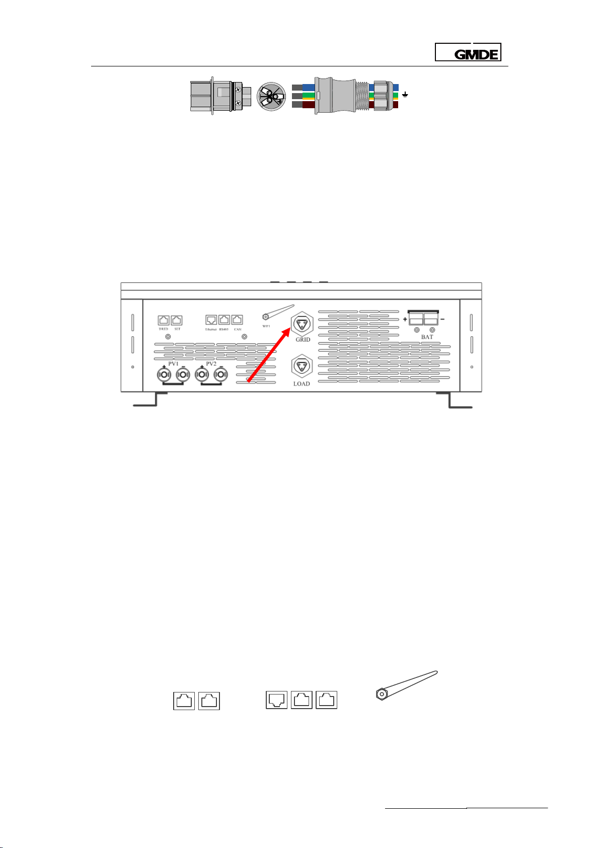
3.4 Electrical Connection
3.4.1 Connectors
The GMDE Powervortex 4600TL / 5200TL are provided with the following connectors, as seen
below from left to right:
Figure 11 Powervortex 4600TL / 5200TL Interfaces
Communication-interface includes:
1. Ethernet/ RS 485/CAN/BAT
2. 2 pairs of PV input terminals.
3. One AC Grid connector (L1/N/G), which can connect to power grid and other load(the
- 19 -

Global Mainstream Dynamic Energy Technology Ltd.
User Manual
PV1 PV2
GRID
LOAD
WIFI
CANRS485Ethernet
BAT
SETDRED
GRID
LOAD
same AC Bus)
4. One AC Load connector (L1/N/G), which can connect to the emergency load
5. 1 pairs of Battery input terminals.
*Definition of Loads:
Emergency load: the load that continues to be powered when the grid failure happens.
Other load: is connected on the AC grid side, stop working when the grid failure happens.
3.4.2 DC Connection
DC Connection procedure is shown in the following steps:
1. Switch off the DC Switch on the Powervortex 4600TL / 5200TL before connection;
2. Insert the MC4 terminals from PV panels into the positive and negative terminals of PV1, PV2
as shown in Figure 12 respectively.
Figure 12 PV connection – PV input terminals
3. Connect the red connector (positive) and the blue / black connector (negative) from the
battery packs with the BAT connectors as shown in Figure 12 respectively. The battery interface
must be connected and locked when the system running.
3.4.3 AC Connection
There is one AC output terminal to the grid and one AC output to the Load as shown in the
following figure:
Figure 13 AC output terminals
1. The “GRID” AC output terminal is equipped with aviation plug.
2. Insert male connector from the grid into the female connector “GRID” on the Powervortex
4600TL / 5200TL.
- 20 -
Global Mainstream Dynamic Energy Technology Ltd.
User Manual
L
N
L
N
WIFI
CANRS485Ethernet
SETDRED
Figure 14 “AC GRID” AC output terminal-aviation plug
3. The female connector of the aviation plug has already been installed at the interface of the
hybrid inverter. The male connector could be found in the packing box.
Please find the recommended AC output cable size:
1. Do not use cables of which losses exceed 1%.
2. L (Power line), N (Neutral), G (PE): Ø 6mm 2
The detailed installation procedures of this AC output terminal is explained as following figures:
Figure 15 AC connection-“GRID” connection
Similarly, the “LOAD” AC output terminal is also equipped with aviation plug. Insert male
connector from the important load into the female connector “LOAD” on the Powervortex
4600TL / 5200TL.
3.4.4 Communication Interface Port
Please refer to the following procedures of the communication connection.
Powervortex 4600TL / 5200TLprovidefour types of communication ports:
1. DRED: Inverter demand response modes
2. SET: for special setting according to Australia’s grid rules.
3. Ethernet (Reserved): for future extension of LAN, now the internet connection way is Wifi
RS485: to connect with the RS485 port on the battery packs and also for firmware update
CAN (Reserved)
Figure 16 Communication ports on the Powervortex 4600TL / 5200TL
- 21 -

Global Mainstream Dynamic Energy Technology Ltd.
User Manual
Pin No.
Illustration
1
--
2
--
3
Data+
4
GND
5
GND
6
Data-
7
5V
8
5V
RS485 Configuration:
GMDE inverter uses RJ45 jacks as the RS485 communication port. The RJ45 plug pin allocation is
illustrated by Figure
Figure 17 RJ45 plug pins allocation
Table 4 RJ45 plug pins illustration
4. System Settings
4.1 LCD
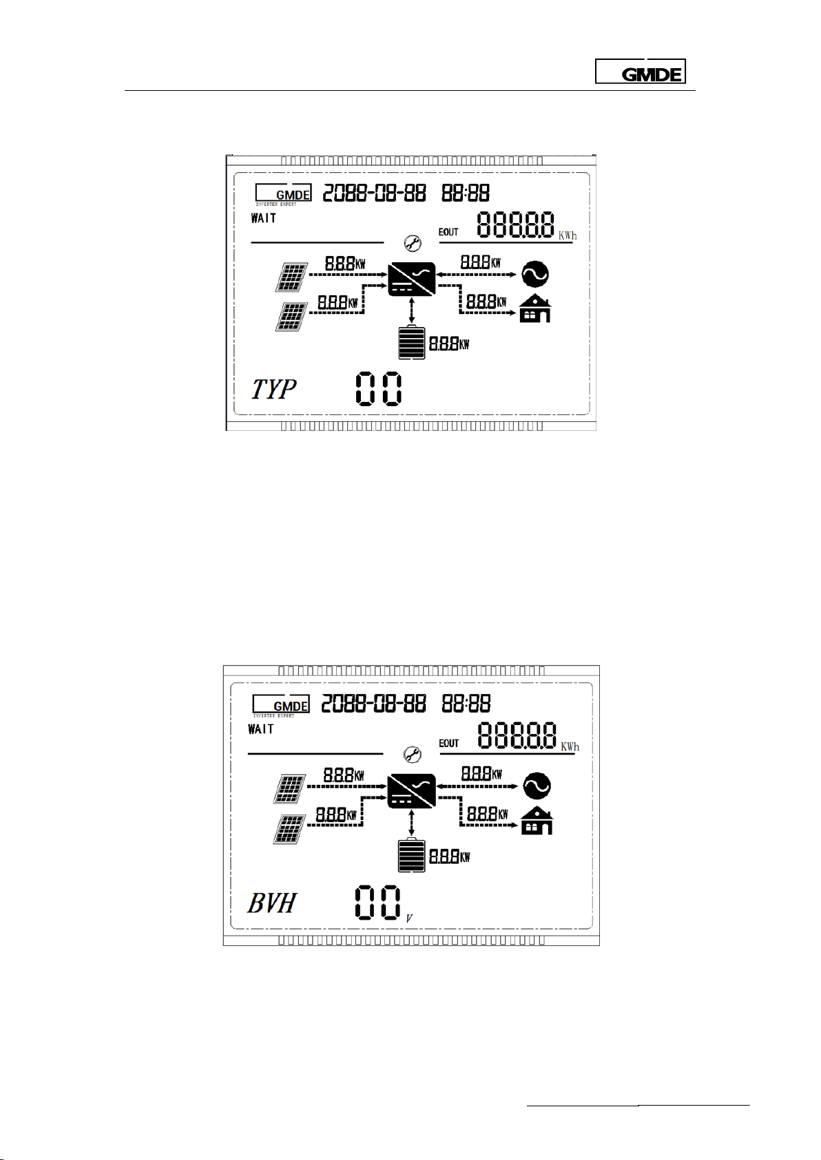
4.1.1 LCD Interface
All information related to the inverter can be obtained from the LCD display. There are
4navigation keys on the LCD display panel. The functions of these navigation keys and
indication lights on the LCD screen are illustrated as below:
Figure 18 LCD display
- 22 -

Global Mainstream Dynamic Energy Technology Ltd.
User Manual
Item
Symbol
Meaning
Illustration
①
ESC
Cancel
Move back to the upper item or close
②
▲
Up
Move back to the upper item or previous
page
③
▼
Down
Move forward to next item or next page
④
OK
Enter/ Escape
Enter into or exit from the current page
Table5 LCD Function introduction
Item
Definition
Description
PV operation light
Light on when hybrid inverter system is running smoothly
Battery operation
light
Light on if the communication between PV inverter and
Battery manger is fine
WiFi operation light
Light on when the WiFi is running
Warning light
Light on when system warning happens
No.
Item
Definition
1
Time
Current date and time
2
Systemstatus
Operating status of the inverter(Wait / Start / Normal /
Warning / Fault/Off-grid)
3
Energy
EIN/EOUT/EPV (EIN: battery charging energy; EOUT: battery
discharging energy; EPV: PV generated energy)
4.1.2 LCD Indication Lights
4.1.3 LCD Display Definition
Table 6 LCD status light definition
Figure 19 LCD display
- 23 -

Global Mainstream Dynamic Energy Technology Ltd.
User Manual
Item list
Display content
PV1
Voltage
Current
PV2
Voltage
Current
BAT
Voltage
Current
AC
GRID voltage(on-grid)
GRID voltage(on-grid)
EMERGENCY LOAD voltage(off-grid)
EMERGENCY LOAD current(off-grid)
TEM
PV side temperature
Battery DCDC side temperature
FRE
Grid frequency
ET1
Daily PV production
SOC
Battery capacity
SWC
software version No. of Powervortex 4600TL / 5200TLcommunication conversion
board
SWM
CPU software version No. of Powervortex 4600TL / 5200TL DPS1
SWS
CPU software version No. of Powervortex 4600TL / 5200TL DPS2
SWB
CPU software version No. of Powervortex 4600TL / 5200TL DPS3
4
PV1 Power
Power of PV1
5
PV2 Power
Power of PV1
6
Grid power
Power out/into the grid
7
Load power
The current load power
8
Battery power
Battery charging / discharging power
9
Menu
Menu and data display
Item
Description
PW
Password 6666 or 1111
TIM
Time
TYP
Battery type
00
Lithium-ion battery(default)
01
Lead battery
Table 7 LCD display definition
4.1.4 LCD Display Menu Definition
The LCD menu includes display and setting menus. The display menu shows system parameters
and their values. The setting menu is to configure the values ofparameters to ensure the system
is running according to customer requirements.
Users can change flip bypressing “▲”, “▼”button to check information on the display menu. To
enter the setting menu, long pressing the“OK”button for 3 seconds. Choose parameters to be
set by pressing“▲”, “▼” buttons.
Parameter list and definition on display menu:
Table 8 LCD display menu content
4.1.5 LCD Setting Menu
Setting the device when initial commissioning.
- 24 -

Global Mainstream Dynamic Energy Technology Ltd.
User Manual
BVH
Battery charging stop voltage (default 0054V)
BVL
Battery discharging stop voltage(lithium default 0046V, lead-acid default 0047V)
Id
Max discharging current(default 0050A)
Ic
Max charging current(default 0050A)
CER
Certification
00
AS4777 (default)
01 02
CNY
PV
connection
01
Only PV1
02
Only PV2
03
PV independent (default)
04
PV parallel
MDE
Operation
mode
00
PV self of use(default)
01
Forced Time of Use(TOU)
00charging time
01discharging time
02
Back up reserved
04
Slave mode
ADR
Meter address(001-255)
CT
Current transformer(01-99)
BMS
00
Pylon
Communication mode: RS485
SOC
Discharging stop capacity (default 15%)
FED
Grid feed-in power XXXX%(5000*x%)X default 100
RST
Restore to the default factory setting(RST1111)
Table 9 LCD parameter settings
Note: the LCD background light will be turned off if no actions within 2 minutes.
Please turn on the DC-switch or get the grid connected with the Powervortex 4600TL /
5200TL,wait until the LCD is displaying the interface as shown in Figure 20. Long pressing“OK”
button for 3 seconds on the display menu to enter into setting menu, the password input
interface as Figure will be displayed.
- 25 -

Global Mainstream Dynamic Energy Technology Ltd.
User Manual
Figure 20 Display menu
4.1.5.1 Password
Figure 21 Setting interface
The default password for setting is 6666 or 1111, users can key in the password through
pressing“▲”,“▼”and “OK ”buttons. Press “OK” button to enter into time setting as Figure 22
showed and choose different information by pressing“▲”,“▼”buttons. Users can press “ESC”
button to quit from setting and enter into the display menu.
4.1.5.2 Setting Time
Figure 22 Time setting
TIM refers to system time, press ”OK” button to modify the time. Press “▲”,“▼”and “OK” buttons
to adjust the numbers on the interface successively, press “OK” to finish the setting. After time
setting, the system will automatic enter into the battery type interface as inFigure .
- 26 -
Global Mainstream Dynamic Energy Technology Ltd.
User Manual
4.1.5.3 Setting Battery Type
Figure 23 Battery type setting
TYP refers to battery type , 00 is referring to lithium battery; please set TYP as 01 when the battery
type is lead-acid.
The default battery type is lithium-ion, press ”OK” button and input the corresponding battery
type code to modify. Press “OK” to finish the setting and you will enter the setting interface as
shown in Figure .
4.1.5.4 Setting Battery Charging Cut-off Voltage
Figure 24 charging cut-off voltage setting
BVH refers to battery charging cut-off voltage. The BVH setting range is 40V-60V, the default
value is 54V.Please set the voltage according to the battery recommended value for different
- 27 -

Global Mainstream Dynamic Energy Technology Ltd.
User Manual
battery types.
Press “OK” to modify setting on this parameter. Make sure the BVH value input here is higher
than the BVL value set in Section 4.1.5.5. Press “OK” to finish this setting and you will enter the
setting interface as shown in Figure .
4.1.5.5 Setting Battery Discharging Cut-off Voltage
Figure 25 discharging cut-off voltage setting
BVL refers to battery discharging cut-off voltage with setting range from 40V to 60V. Default BVL
value is 46V for lithium battery and 47V for lead-acid battery. Please set the voltage according
to the battery recommended value for different battery types.
Press “OK” to modify the value and please make sure the BVL value input is smaller than the BVH
value in 4.1.5.4. Press “OK” to finish this setting and you will enter the setting interface as shown in
Figure .
- 28 -
Global Mainstream Dynamic Energy Technology Ltd.
User Manual
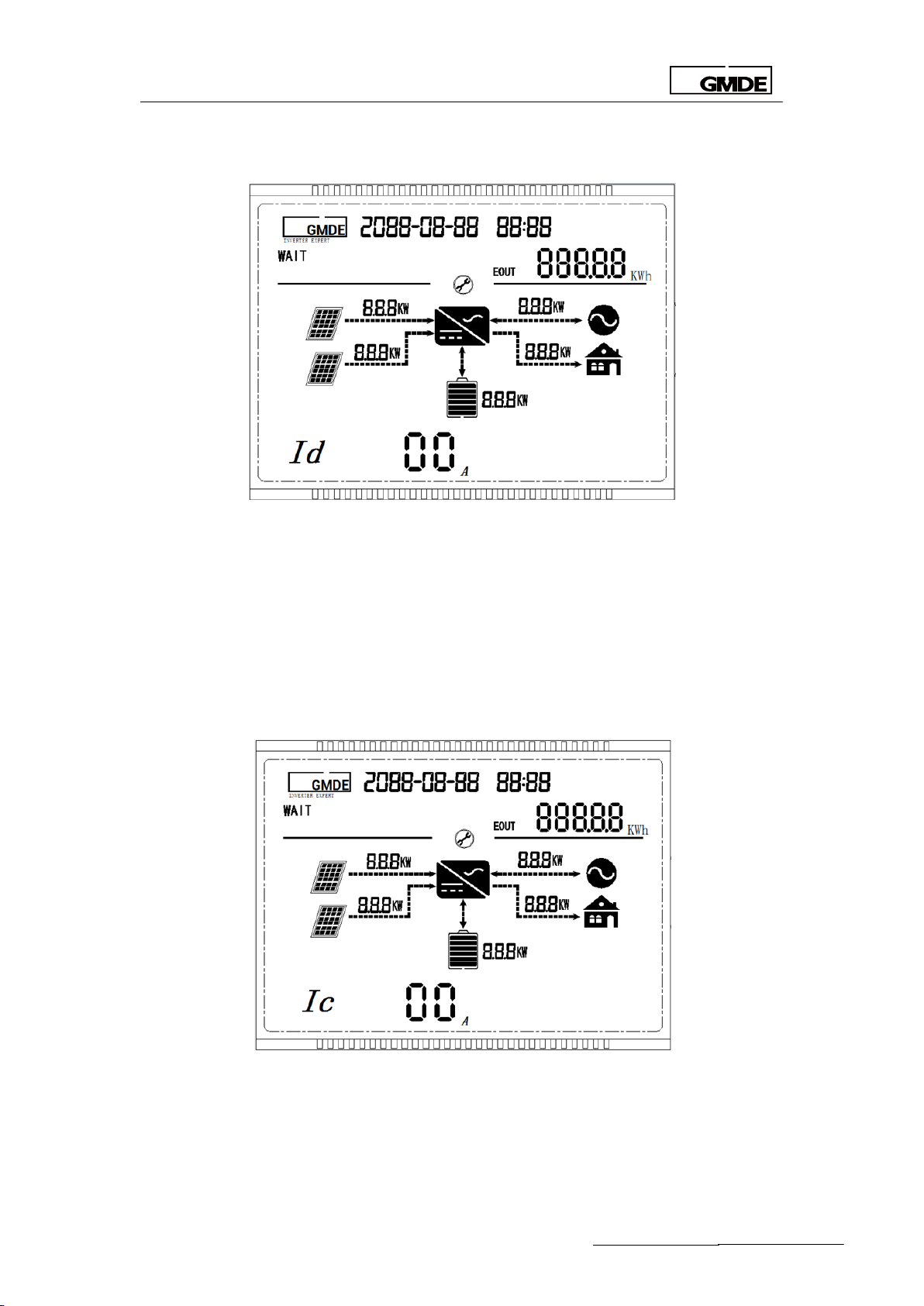
4.1.5.6 Setting Maximum Discharging Current
Figure 26 discharging current setting
Id refers to the maximum discharging current with setting range from 5A to 80A. The default
value is 60A. Please set this current value according to the battery recommended value of
different battery types. Press “OK” to finish this setting and you will enter the setting interface as
shown in Figure .
4.1.5.7 Setting Battery Maximum Charging Current
Figure 27 maximum charging current setting
Ic refers to the maximum charging current with setting range from 5A to 80A. The default value is
60A. Please set this current value according to the battery recommended value of different
battery types. Press “OK” to finish this setting and you will enter the setting interface as shown in
- 29 -

Global Mainstream Dynamic Energy Technology Ltd.
User Manual
Figure .
4.1.5.8 Setting Grid Certification Standards
Figure 28 certification standards setting
CER refers to the grid regulation where this system is applied in. The CER codes mean: 00 refer to
comply with the AS4777 in Australia. Please finish this setting according to the local
grid-connection regulations. Press “OK” to finish this setting and you will enter the setting
interface as shown in Figure .
4.1.5.9 Setting PV String Connection Way
Figure 29 string connection way setting
CNY refers to the connection way of PV strings. The CNY should be set to 01 when Powervortex
4600TL / 5200TL only have PV1 port connected with PV string; the CNY should be set to 02 when
Powervortex 4600TL / 5200TL only have PV2 port connected with PV string; the CNY should be set
- 30 -

Global Mainstream Dynamic Energy Technology Ltd.
User Manual
to 03 when Powervortex 4600TL / 5200TL PV1 and PV2 ports are connecting with different PV
strings respectively. The CNY should be set to 04 when Powervortex 4600TL / 5200TL PV1 and PV2
ports are connecting with same PV string.
The system default value is 03, please press”OK”to modify it. Press “OK” to finish this setting and
you will enter the setting interface as shown in Figure .
Note:This setting should be operated when the Powervortex 4600TL / 5200TL is under ”wait”
status,otherwise“E05” Error might occur.
4.1.5.10 Setting Operation Mode
Figure 30 Operation mode setting
MDE refers to operation mode. The MDE code 00refers to self-use mode, 01 refers to time-of-use
mode. The default value is 00 and press “OK” to modify it.
If modify MDE value into 01 as shown in Figure , press “OK” the system will enter the charging
time range setting interface as shown in Figure . For example, if you want the system start to
charge the battery at 22.00 and stop charging at 5.00 next morning, then please set the digits
on Figure as “22:00”, “05:00” respectively. The charging current is the same as the Ic that has
been set in Section 4.1.5.7.
Press “OK” to enter into the discharging time range setting interface as shown in Figure 30. Like
setting the charging time range as above, if to discharge the battery from 8am to 5pm(17:00)
every day, then please set the digits on Figure 30 as “08:00”,”17:00” . The discharging current is
the same as the Id current that has been set in 4.1.5.6.
- 31 -

Global Mainstream Dynamic Energy Technology Ltd.
User Manual
Figure 31 Time-of-use mode setting
Figure 32 Charging time range setting under time-of-use operation mode
Figure 33 Discharging time range setting under time-of-use operation mode
- 32 -

Global Mainstream Dynamic Energy Technology Ltd.
User Manual
4.1.5.11 Setting Energy Meter Address
Press “OK” to finish the setting in Figure 33 and you will enter the setting interface as shown in
Figure .
Figure 34 Energy meter address setting
ADR refers to energy meter address. Please check the address column on energy meter label,
you will find the meter address is “003”. Press “OK” and change the meter address to“003”
accordingly.
Note: Each meter has a unique address, ensure this value is input correctly.
4.1.5.12 Setting Current Transformer Ratio
Press “OK” to finish the setting in Figure 4 and you will enter the setting interface as shown in
Figure .
- 33 -

Global Mainstream Dynamic Energy Technology Ltd.
User Manual
Figure 35 Current transformer ratio setting
CT refers to current transformer for indirect metering case. Please check the current transfer
ration listed on the current transformer label and press “OK” to modify it.
Note: Different current transformer has different current ratios, please input the right ratio. The
default value is 0001, it’s not necessary to modify this value if no current transformer is
connected in.
4.1.5.13 Setting Lithium-ion BMS Code
Press “OK” to finish this setting and you will enter the setting interface as shown in Figure 36.
Figure 36 Lithium-ion BMS code setting
BMS refers to the BMS code when adopting different lithium-ion battery in the system. If in
Section 4.1.5.3, the TYP is lead-acid, then there is no need to set this value.
The default BMS value is 00, which is for the Plyon battery. Currently, BMS and battery from Plyon
is the only one available in the standard system. So this value doesn’t need to modify.
Lithium battery type, users can ignore this option if the battery setting type is lead-acid battery.
The BMS default value is 00 which is corresponding with pylon battery.The system is only
compatible with Pylon battery protocol,so no need to do any extra setting.
Please press “▼”to enter the interface as figure 36 showed.
- 34 -

Global Mainstream Dynamic Energy Technology Ltd.
User Manual
4.1.5.14 Setting Battery State of Charge (SoC)
Figure 37 SoC setting
SOC refers to the left battery capacity ratio. For example, if set SOC as 15% ,the system will stop
discharging the battery when the battery capacity is reduced to 15%;
The SOC default value is 15%, please press “OK” to modify it.
4.1.5.15 Setting Feed-in Grid Percentage
Figure 38 Feed-in grid percentage setting
FED refers to feed-in grid percetage. The system is not allowed to feed any energy into the grid if
the FED value is set to 0%. The system is free to export to the grid if the FED setting to 0100%.If the
FED is set to 10%, then the largest power allowed to be fed into the grid is 5000W*10%=500W.
- 35 -

Global Mainstream Dynamic Energy Technology Ltd.
User Manual
The default FED value is 100%, please press”OK”to modify it.
4.1.5.16 Restore to Factory Setting
Press “▲”to enter setting interface as shown in Figure .
Figure 39 Restore to factory setting
RST refers to restore to the factory setting. Please input the value ”1111” if you need to restore
the system into the initial setting out of factory. Press “ESC” to quit from the setting page and
enter the display menu.
Note: The setting should be operated when the Powervortex4600TL / 5200TL is under “wait”
status, otherwise the ”E05”error might occur to the system.
4.2 WiFi
4.2.1WiFi Function
Powervortex 4600TL / 5200TL solar battery hybrid inverter has integrated WiFi module. So the user
can be connected to the Internet after WiFi- connecting and setting. Then log in the GMDE web
portal or GMDE APP on your smart phone, you can monitor your system status timely and
remotely.
Before setting the WiFi:
1. The WiFi indication light on Powervortex4600TL / 5200TL panel is lighting ;
2. WiFi signal is available on the installation site to be received by the antenna integrated in the
inverter
- 36 -

Global Mainstream Dynamic Energy Technology Ltd.
User Manual
Figure 40 WiFi Antenna
4.2.2 WiFi Configuration
4.2.2.1Get Connected with the Inverter Wi-Fi
End user can connect to the WiFi generated by inverter via smart ends like smart phone, PC or
iPad etc. Choose the Wifi portal created by the corresponding inverter, whose network name is
GMDE_XXXXXXXX (XXXXXXXX part is the Monitor SN), as shown in figure below.
Figure 41 Powervortex 4600TL / 5200TL Wifi network
Note: in this step above, the most important thing is to power on the inverter and find out the
Wi-Fi generated by the inverter from the WLAN options page on your Mobile/ Ipad /computer.
After connecting to the inverter WiFi portal, open your Internet browser, input 11.11.11.1 to enter
into the WiFi setting page. Log into the page with:
Account: admin
Password: admin
Tick the checkbox below and click “yes” to finish the setting.
Figure 42 Logging in for WiFi setting
- 37 -

Global Mainstream Dynamic Energy Technology Ltd.
User Manual
4.2.2.2Account and Password Setting
Please set your Wifi network name and the password:
SSID: name of the Wi-Fi in your house
Key: password of the Wi-Fi in your house
Figure 43 Input your home Wi-Fi data
Note: in this step in Figure 43, the SSID refer to the Wi-Fi Name in your house (the normal Wi-Fi
generated by your Power router and your Smart phone or PC normally connects with). Input
your Wi-Fi password into the “Key” table. Don’t input “MDE”, as MDE is the WiFi Name in our
office and be input as an example.
Save your setting and restart, wait at least 2mins. If the device IP address is no longer 0.0.0.0,
then the device is connected to the Internet successfully.
Figure 44 IP address
If you’ve registered on the GMDE web portal: http://portal.global-mde.com/, then login and
add inverter site. If not, please register first according to the following steps.
4.2.2.2 User Account Registration
Registration procedures are as following:
Visit your website portal(http://portal.global-mde.com/) and log in
- 38 -

Global Mainstream Dynamic Energy Technology Ltd.
User Manual
Figure 45 Log in
Key in Username, password, e-mail address and monitor SN. Please notice: the Monitor SN is the
Suffix of the GMDE_XXXXXXXX. For example: if the Wifi of one device is GMDE_3E227BB2, then
the Monitor SN you should key in is 3E227BB2
Figure 46 GMDE registration window
Add the plant and inverter information after registration
- 39 -

Global Mainstream Dynamic Energy Technology Ltd.
User Manual
High electric voltage!
Risk of death or personal injury by electric shock!
Never work with live wires! It is prior to all connection and maintenance work.
Warning!
Danger from residual voltage out of capacitors.
You must wait until the capacitors have fully discharged. Discharge takes
around15 minutes.
Caution!
Danger from inadequate grounding.
An inadequate grounding conductor connection can cause serious injuries to
persons and damage to properties.
Fault
messages
Explanation
Action
Figure 47 Add plant and inverter information
As shown in Figure 47, a couple of plants can be managed under one account. A couple of
inverters can be added into under each plant.
My sites: plant list
Inverter: inverters under the plant
Setting: plant related parameter setting
Change password: modify the log in password
5 Troubleshooting
5.1 Safety during Troubleshooting
Note:
1. Make sure that the AC and DC wires are not charged.
2. The connection area should only be opened by a licensed electrician.
5.2 Faults
A fault can be divided into two catalogues: a permanent failure and a temporary failure. A
‘permanent failure’ is defined by a fault having been present for more than 15 minutes and
cannot be acknowledged by inverter’s auto-restart. Unlike permanent failure, a “transient
failure" is automatically acknowledged by the inverter.
5.3 Fault Messages and Actions List
When failure occurs, warning codes will be displayed on the LCD screen. The latest 20 fault
codes will be stored in the EEPROM. Check the history fault information via long-pressing the key
“ESC”. Detailed fault definitions are listed as below:
- 40 -

Global Mainstream Dynamic Energy Technology Ltd.
User Manual
E01
The DC injection of grid current is out of
range.
Contact the service if the error
occurs repeatedly.
E02
Different value between master and
slave CPU.
Wait until the controller has
re-stabilized.
E03
Different value between master and
slave for GFCI.
Wait until the controller has
re-stabilized.
E04
The current sensor is abnormal
Wait until the controller has
re-stabilized.
E05
Inverter current is over the tolerable
value
E06
Residual current is out of range
Wait until the controller has
re-stabilized.
E07
The GFCI detection circuit is abnormal.
Wait until the controller has
re-stabilized.
E08
Isolation resistance of PV-plant out of
tolerable range before connecting to
the grid.
Check insulation of the system.
E09
Rly-Warning
Wait until the controller has
re-stabilized.
E10
Master-grid voltage measurement-value
out of tolerable range.
Re-measure line voltage , contact
the service if grid voltage is within
normal range.
E11
The master-frequency is out of tolerable
range.
Check system frequency and line
voltage. Contact the Service if
system frequency is within normal
range.
E13
No-Utility
Re-measure line voltage; contact
the Service if line voltage is within
normal range.
E14
PV input voltage is over the tolerable
maximum value.
Check the voltage of solar panels
E15
Inverter internal communication fail
Please contact the service if
continue occur
E16
PV over temperature
Allow the unit to cool down
E17
Different value between master and
slave for grid voltage.
Possibly caused by switching actions
on the net. Re-measure line voltage.
Contact the Service if line voltage is
within normal range.
E18
Different value between master and
slave for output DC current.
Wait until the controller has
re-stabilized.
E19
Different value between master and
slave for output DC current.
Wait until the controller has
re-stabilized.
E20
DC bus soft start is over time
Check input voltage
E21
PV inverter soft start is over time
Check the utility
- 41 -

Global Mainstream Dynamic Energy Technology Ltd.
User Manual
E22
PV inverter bus voltage is too low.
Wait until the controller has
re-stabilized.
E23
PV inverter Bus voltage is too high.
Wait until the controller has
re-stabilized.
E24
Different value between master and
slave for grid frequency.
Check system frequency and line
voltage. Contact the Service if
system frequency is within normal
range.
E25
Boost current is over the tolerable value.
Restart system
E26
Battery Manager input voltage is too
high
Re-confirm battery input voltage
E27
Battery Manager over temperature
Waiting for Battery Manager cooling
down
E28
Battery Manager boost current warning
Re-start Battery Manager
E29
PV inverter fan locked
Check fan
E30
Battery Manager fan locked
Check fan
E31
PV inverter GFCI fault
Re-start PV inverter, contact the
service if continue occur
E32
PV inverter current-sensor fault
Re-start PV inverter, contact the
service if continue occur
E33
PV inverter current is over the tolerate
value
Re-start PV inverter, contact the
service if continue occur
E35
PV inverter Bus fault
Re-start PV inverter, contact the
service if continue occur
E40
PV inverter relay fault
Re-start PV inverter, contact the
service if continue occur
E41
Communication failure between PV
inverter and Battery Manager
Check communication cable
between PV inverter and Battery
Manager
E42
Communication failure between PV
inverter and energy meter
Please check the energy meter and
communication line status
E43
Communication failure between PV and
BMS
Please check BMSand
communication line status
E46 +N
Battery (2+N) over voltage warning
Re-start battery
E47+N
Battery (2+N) low voltage warning
Re-start battery
E48+N
Battery (2+N)Charge Over Current
Warning
Re-start battery
E49+N
Battery (2+N) discharge Over Current
Warning
Re-start battery
E50+N
Battery (2+N)Discharge Temperature
Warning
Re-start battery
E51+N
Battery (2+N) Charge Temperature
Warning
Re-start battery
- 42 -

Global Mainstream Dynamic Energy Technology Ltd.
User Manual
E52+N
Battery (2+N)Under Voltage Warning
Re-start battery
Global Mainstream Dynamic Energy Technology Ltd.
3rd Floor, Building 7, No. 333 Zhujian Rd. Minhang District, Shanghai , China
TEL: +86 21 60710806
FAX: +86 21 61730300
E-mail: Service@global-mde.com
WEB: www.global-mde.com
SKYPE: GMDE Service
Table 10 Fault lists
N = (battery address- 2* 7), only suit for Pylon, Battery address respectively are 2, 3, 4 and 5.
5.4 Fault Acknowledgement
After shutdown due to a fault, the device remains locked against reactivation until the fault is
acknowledged. The fault can only be acknowledged after the cause of the fault has been
eliminated.
To acknowledge the fault messages, press the ESC key or turn the GMDE inverter off with the DC
switch. Wait for a while and turn the device on again.
5.5 Technical Service
- 43 -
 Loading...