

Page 1
User Manual
1KVA- 5KVA
INVERTER / CHARGER
With MPPT Controller
类型: Powervortex
101K24/102K24/103K24/101K48/102K48
/103K48/102K24M/103K24M/102K48M/
103K48M/105K48/105K48P
User Manual
Page 2

Table Of Contents
ABOUT THIS MANUAL ..................................................................................................................................... 1
Purpose................................................................................................................... ......................................... 1
Scope ............................................................................................................................................................... 1
SAFETY INSTRUCTIONS.................................................................................................................... .............. 1
INTRODUCTION ............................................................................................................................................... 2
Features ................................................................... ........................................................................................ 2
Basic System Architecture ............................................................................................................................... 2
Product Overview............................................................................................................................................. 3
INSTALLATION ................................................................................................................................................. 4
Unpacking and Inspection................................................................................................................................ 4
Preparation .......................................................................................... ............................................................ 4
Mounting the Unit ............................................................................ ................................................................. 4
Battery Connection .................................................. ........................................................................................ 5
AC Input/Output Connection ............................................................................................................................ 7
PV Connection ................................................................................................... .............................................. 8
Final Assembly ................................................................................................................................................. 9
Communication Connection........................................................................................................................... 10
Dry Contact Signal ............................................................................................................................ ............. 10
OPERATION ..................................................................................................................................................... 11
Power ON/OFF ................................................................................................................................ .............. 11
Operation and Display Panel ......................................................................................................................... 11
LCD Display Icons ......................................................................................................................................... 12
LCD Setting.................................................................................................................................................... 14
Display Setting ................................................................................ ............................................................... 20
Operating Mode Description ................................................................................................ .......................... 23
Fault Reference Code ...................................................................................................................... .............. 24
Warning Indicator ............................................................................................................ ............................... 25
SPECIFICATIONS ........................................................................................................................................... 26
Table 1 Line Mode Specifications ................................................................................................................... 26
Table 2 Inverter Mode Specifications ............................................................................................................. 27
Table 3 Charge Mode Specifications .............................................................................................................. 28
Table 4 General Specifications ....................................................................................................................... 29
TROUBLE SHOOTING ..................................................................................................................................... 30
Appendix: Approximate Back-up Time Table ........................................................................................... 31
Page 3

ABOUT THIS MANUAL
Purpose
This manual describes the assembly, installation, operation and troubleshooting of this unit. Please read
this manual carefully before installations and operations. Keep this manual for future reference.
Scope
This manual provides safety and installation guidelines as well as information on tools and wiring.
SAFETY INSTRUCTIONS
WARNING: This chapter contains important safety and operating instructions. Read and
keep this manual for future reference.
1. Before using the unit, read all instructions and cautionary markings on the unit, the batteries and all
appropriate sections of this manual.
CAUTION --To reduce risk of injury, charge only deep-cycle lead acid type rechargeable batteries.
Other types of batteries may burst, causing personal injury and damage.
Do not disassemble the unit. Take it to a qualified service center when service or repair is required.
Incorrect re-assembly may result in a risk of electric shock or fire.
To reduce risk of electric shock, disconnect all wirings before attempting any maintenance or cleaning.
Turning off the unit will not reduce this risk.
CAUTION – Only qualified personnel can install this device with battery.
NEVER charge a frozen battery.
For optimum operation of this inverter/charger, please follow required spec to select appropriate cable
size. It’s very important to correctly operate this inverter/charger.
Be very cautious when working with metal tools on or around batteries. A potential risk exists to drop
a tool to spark or short circuit batteries or other electrical parts and could cause an explosion.
Please strictly follow installation procedure when you want to disconnect AC or DC terminals. Please
refer to INSTALLATION section of this manual for the details.
Fuses (3 pieces of 40A, 32VDC for 1KVA, 4 pieces of 40A, 32VDC for 2KVA and 6 pieces for 3KVA, 1
piece of 200A, 58VDC for 4KVA and 5KVA) are provided as over-current protection for the battery
supply.
GROUNDING INSTRUCTIONS -This inverter/charger should be connected to a permanent grounded
wiring system. Be sure to comply with local requirements and regulation to install this inverter.
NEVER cause AC output and DC input short circuited. Do NOT connect to the mains when DC input
short circuits.
Warning!! Only qualified service persons are able to service this device. If errors still persist after
following troubleshooting table, please send this inverter/charger back to local dealer or service center
for maintenance.
2.
3.
4.
5.
6.
7.
8.
9.
10.
11.
12.
13.
1
Page 4
INTRODUCTION
This is a multi-function inverter/charger, combining functions of inverter, MPPT solar charger and battery
charger to offer uninterruptible power support with portable size. Its comprehensive LCD display offers
user-configurable and easy-accessible button operation such as battery charging current, AC/solar charger
priority, and acceptable input voltage based on different applications.
Features
Pure sine wave inverter
Built-in MPPT solar charge controller
Configurable input voltage range for home appliances and personal computers via LCD setting
Configurable battery charging current based on applications via LCD setting
Configurable AC/Solar Charger priority via LCD setting
Compatible to mains voltage or generator power
Auto restart while AC is recovering
Overload/ Over temperature/ short circuit protection
Smart battery charger design for optimized battery performance
Cold start function
Basic System Architecture
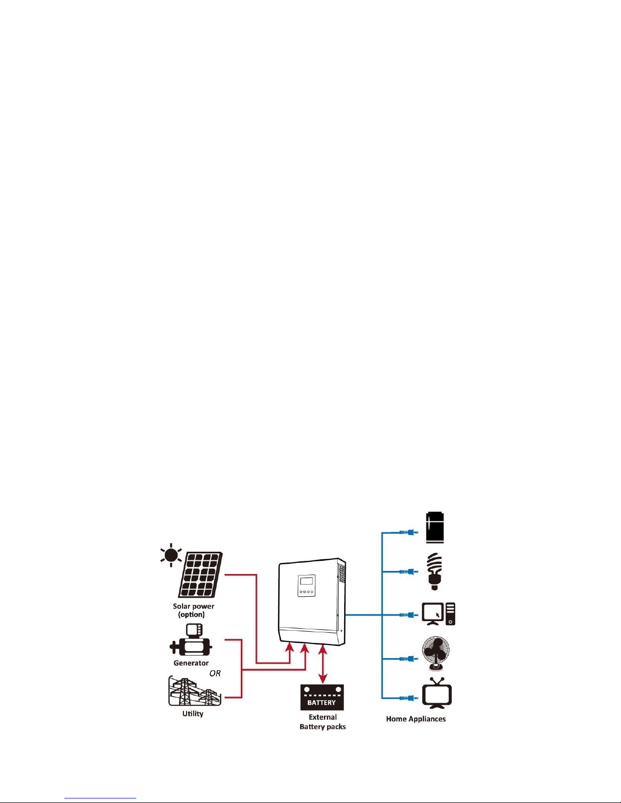
The following illustration shows basic application for this inverter/charger. It also includes following devices to
have a complete running system:
Generator or Utility.
PV modules (option)
Consult with your system integrator for other possible system architectures depending on your requirements.
This inverter can power all kinds of appliances in home or office environment, including motor-type appliances
such as tube light, fan, refrigerator and air conditioner.
Figure 1 Hybrid Power System
2
Page 5

Product Overview
4KVA/5KVA single model
4KVA/5KVA parallel model
LCD display
Status indicator
Charging indicator
Fault indicator
Function buttons
Power on/off switch
AC input
AC output
PV input
1-3KVA model
1.
2.
3.
4.
5.
6.
7.
8.
9.
NOTE: For parallel model installation and operation,
please check separate parallel installation guide for
the details.
10. Battery input
11. Circuit breaker
12. RS232 communication port
13. Parallel communication cable (only for parallel model)
14. Current sharing cable (only for parallel model)
15. Dry contact
3
Page 6

INSTALLATION
Unpacking and Inspection
Before installation, please inspect the unit. Be sure that nothing inside the package is damaged. You should
have received the following items inside of package:
The unit x 1
User manual x 1
Communication cable x 1
Software CD x 1
Preparation
Before connecting all wirings, please take off bottom cover by removing two screws as shown below.
Mounting the Unit
Consider the following points before selecting where to install:
Do not mount the inverter on flammable construction
materials.
Mount on a solid surface
Install this inverter at eye level in order to allow the LCD
display to be read at all times.
The ambient temperature should be between 0°C and 55°C
to ensure optimal operation.
The recommended installation position is to be adhered to
the wall vertically.
Be sure to keep other objects and surfaces as shown in the
right diagram to guarantee sufficient heat dissipation and
to have enough space for removing wires.
SUITABLE FOR MOUNTING ON CONCRETE OR
OTHER NON-COMBUSTIBLE SURFACE ONLY.
4
Page 7
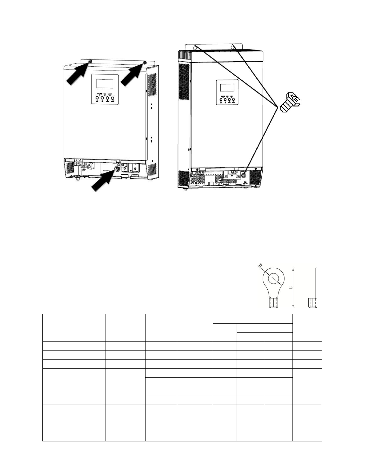
Install the unit by screwing three screws.
1-3KVA 24V, 1KVA/3KVA 48V model
2-3KVA 24V/48V Plus, 4-5KVA 48V model
Battery Connection
CAUTION: For safety operation and regulation compliance, it’s requested to install a separate DC over-current
protector or disconnect device between battery and inverter. It may not be requested to have a disconnect
device in some applications, however, it’s still requested to have over-current protection installed. Please refer
to typical amperage in below table as required fuse or breaker size.
Ring terminal:
WARNING! All wiring must be performed by a qualified personnel.
WARNING! It's very important for system safety and efficient operation to use
appropriate cable for battery connection. To reduce risk of injury, please use the
proper recommended cable and terminal size as below.
Recommended battery cable and terminal size:
5
Model Typical
Amperage
Battery
Capacity
Wire Size Ring Terminal Torque
Value
Cable
mm
2
Dimensions
D (mm) L (mm)
1KVA 48V 20A 100AH 1*14AWG 2 6.4 21.8 2~ 3 Nm
1KVA 24V, 2KVA 48V 33A 100AH 1*10AWG 5 6.4 22.5 2~ 3 Nm
3KVA 48V 50A 100AH 1*8AWG 8 6.4 23.8 2~ 3 Nm
2KVA 24V
66A
100AH 1*6AWG 14 6.4 29.2
2~ 3 Nm
200AH 2*10AWG 8 6.4 23.8
3KVA 24V
100A
100AH 1*4AWG 22 6.4 33.2
2~ 3 Nm
200AH 2*8AWG 14 6.4 29.2
4KVA
66A
200AH
1*4AWG 22 6.4 33.2
2~ 3 Nm
2*8AWG 14 6.4 29.2
5KVA
87A
200AH
1*4AWG 22 6.4 33.2
2~ 3 Nm
2*8AWG 14 6.4 29.2
Page 8
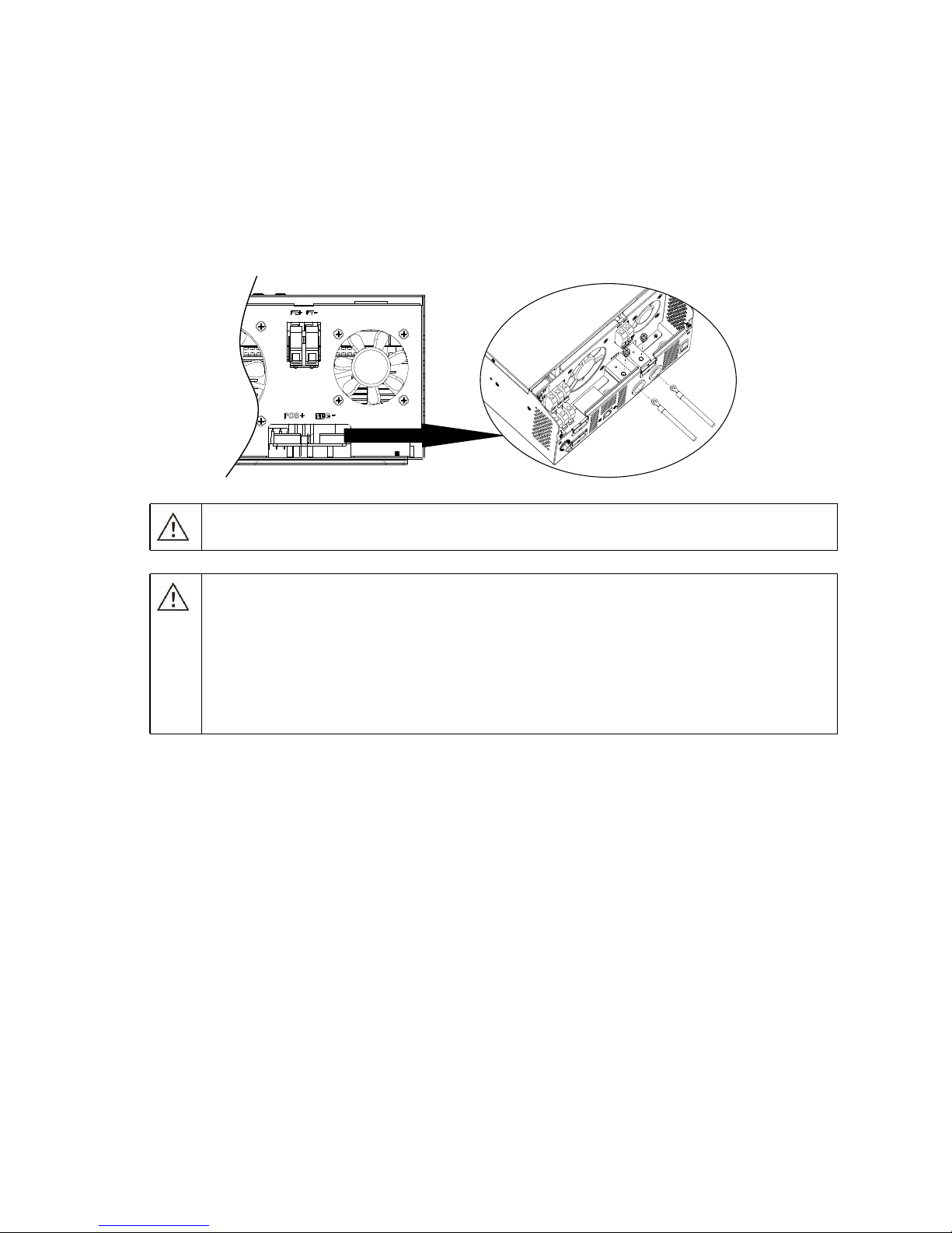
Please follow below steps to implement battery connection:
1. Assemble battery ring terminal based on recommended battery cable and terminal size.
2. Connect all battery packs as units requires. It’s suggested to connect at least 100Ah capacity battery for
1-3KVA model and at least 200Ah capacity battery for 4KVA/5KVA model.
NOTE: Please only use sealed lead acid battery or sealed GEL/AGM lead-acid battery.
3. Insert the ring terminal of battery cable flatly into battery connector of inverter and make sure the bolts are
tightened with torque of 2-3 Nm. Make sure polarity at both the battery and the inverter/charge is correctly
connected and ring terminals are tightly screwed to the battery terminals.
6
CAUTION!! Do not place anything between the flat part of the inverter terminal and the ring
terminal. Otherwise, overheating may occur.
CAUTION!! Do not apply anti-oxidant substance on the terminals before terminals are
connected tightly.
CAUTION!! Before making the final DC connection or closing DC breaker/disconnector, be sure
positive (+) must be connected to positive (+) and negative (-) must be connected to negative
(-).
WARNING: Shock Hazard
Installation must be performed with care due to high battery voltage in series.
Page 9

AC Input/Output Connection
CAUTION!! Before connecting to AC input power source, please install a separate AC breaker between
inverter and AC input power source. This will ensure the inverter can be securely disconnected during
maintenance and fully protected from over current of AC input. The recommended spec of AC breaker is 10A
for 1KVA, 20A for 2KVA, 32A for 3KVA, 40A for 4KVA and 50A for 5KVA.
CAUTION!! There are two terminal blocks with “IN” and “OUT” markings. Please do NOT mis-connect input
and output connectors.
WARNING! All wiring must be performed by a qualified personnel.
WARNING! It's very important for system safety and efficient operation to use appropriate cable for AC input
connection. To reduce risk of injury, please use the proper recommended cable size as below.
Suggested cable requirement for AC wires
Please follow below steps to implement AC input/output connection:
1.
2.
3.
Before making AC input/output connection, be sure to open DC protector or disconnector first.
Remove insulation sleeve 10mm for six conductors. And shorten phase L and neutral conductor N 3 mm.
Insert AC input wires according to polarities indicated on terminal block and tighten the terminal screws. Be
sure to connect PE protective conductor (
→Ground (yellow-green)
L→LINE (brown or black)
N→Neutral (blue)
) first.
4. Then, insert AC output wires according to polarities indicated on terminal block and tighten terminal screws.
Be sure to connect PE protective conductor (
→Ground (yellow-green)
L→LINE (brown or black)
N→Neutral (blue)
) first.
7
WARNING:
Be sure that AC power source is disconnected before attempting to hardwire it to the unit.
Model Gauge Torque Value
1KVA 16 AWG 0.5~ 0.6 Nm
2KVA 230VAC 14 AWG 0.8~ 1.0 Nm
2KVA 120VAC
3KVA
12 AWG
1.2~ 1.6 Nm
4KVA 10 AWG 1.4~ 1.6Nm
5KVA 8 AWG 1.4~ 1.6Nm
Page 10
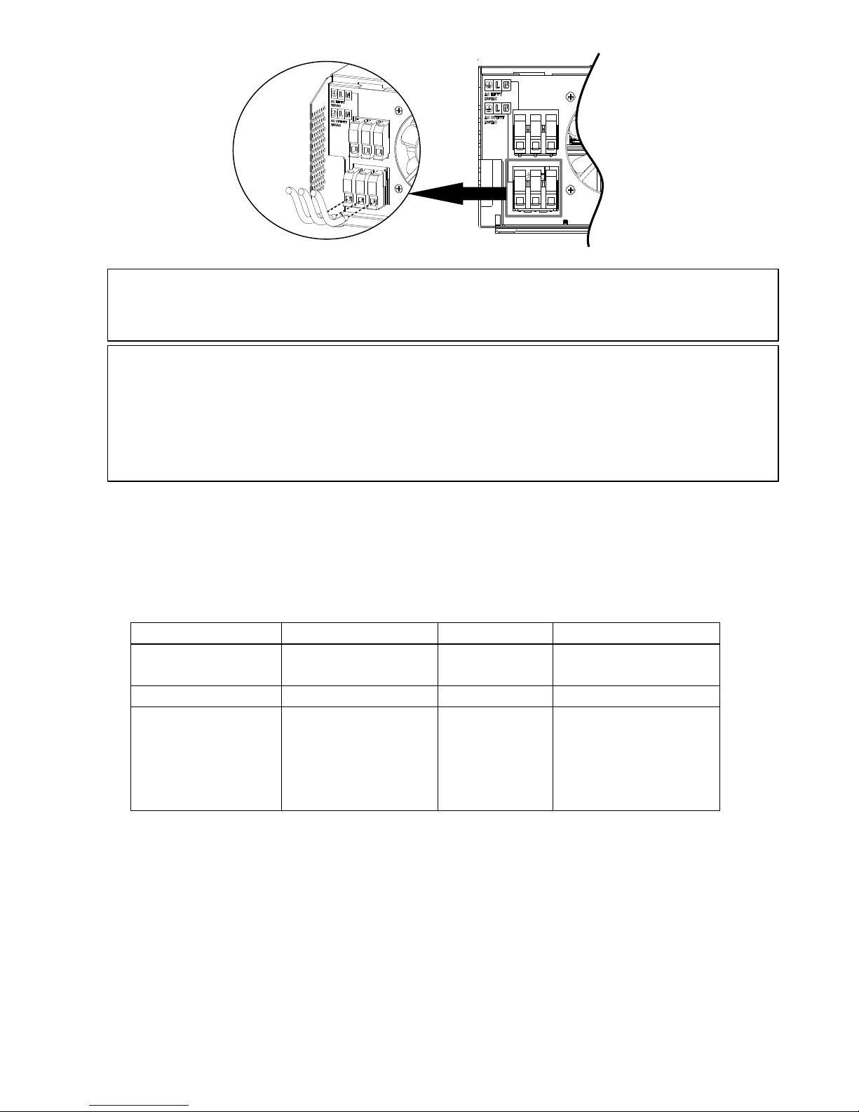
5. Make sure the wires are securely connected.
PV Connection
CAUTION: Before connecting to PV modules, please install separately a DC circuit breaker between inverter
and PV modules.
WARNING! All wiring must be performed by a qualified personnel.
WARNING! It's very important for system safety and efficient operation to use appropriate cable for PV
module connection. To reduce risk of injury, please use the proper recommended cable size as below.
8
Model Typical Amperage Cable Size Torque
1KVA 24V / 2KVA 24V/
3KVA 24V
25A
12 AWG
1.2~1.6 Nm
1KVA 48V / 3KVA 48V 18A 14 AWG 1.2~1.6 Nm
2KVA 24V Plus
3KVA 24V Plus
2KVA 48V Plus
3KVA 48V Plus
4KVA / 5KVA
60A
8 AWG
1.4~1.6 Nm
CAUTION: Important
Be sure to connect AC wires with correct polarity. If L and N wires are connected reversely, it may cause
utility short-circuited when these inverters are worked in parallel operation.
CAUTION: Appliances such as air conditioner are required at least 2~3 minutes to restart because it’s required
to have enough time to balance refrigerant gas inside of circuits. If a power shortage occurs and recovers in a
short time, it will cause damage to your connected appliances. To prevent this kind of damage, please check
manufacturer of air conditioner if it’s equipped with time-delay function before installation. Otherwise, this
inverter/charger will trig overload fault and cut off output to protect your appliance but sometimes it still causes
internal damage to the air conditioner.
Page 11

PV Module Selection:
When selecting proper PV modules, please be sure to consider below parameters:
1. Open circuit Voltage (Voc) of PV modules not exceeds max. PV array open circuit voltage of inverter.
2. Open circuit Voltage (Voc) of PV modules should be higher than min. battery voltage.
Please follow below steps to implement PV module connection:
1.
2.
Remove insulation sleeve 10 mm for positive and negative conductors.
Check correct polarity of connection cable from PV modules and PV input
connectors. Then, connect positive pole (+) of connection cable to positive
pole (+) of PV input connector. Connect negative pole (-) of connection
cable to negative pole (-) of PV input connector.
3. Make sure the wires are securely connected.
Final Assembly
After connecting all wirings, please put bottom cover back by screwing two screws as shown below.
1KVA/2KVA/3KVA 2KVA Plus/3KVA Plus/4KVA/5KVA
9
Solar Charging Mode
INVERTER MODEL
1KVA 24V
2KVA 24V
3KVA 24V
1KVA 48V
3KVA 48V
2KVA 24V
Plus/ 3KVA
24V Plus
2KVA 48V
Plus/3KVA 48V
Plus/ 4KVA/5KVA
Max. PV Array Open Circuit Voltage 75Vdc max 102Vdc max 145Vdc
PV Array MPPT Voltage Range 30~66Vdc 60~88Vdc 30~115Vdc 60~115Vdc
Min. battery voltage for PV charge 17Vdc 34Vdc 17Vdc 34Vdc
Page 12
Communication Connection
Please use supplied communication cable to connect to inverter and PC. Insert bundled CD into a computer and
follow on-screen instruction to install the monitoring software. For the detailed software operation, please
check user manual of software inside of CD.
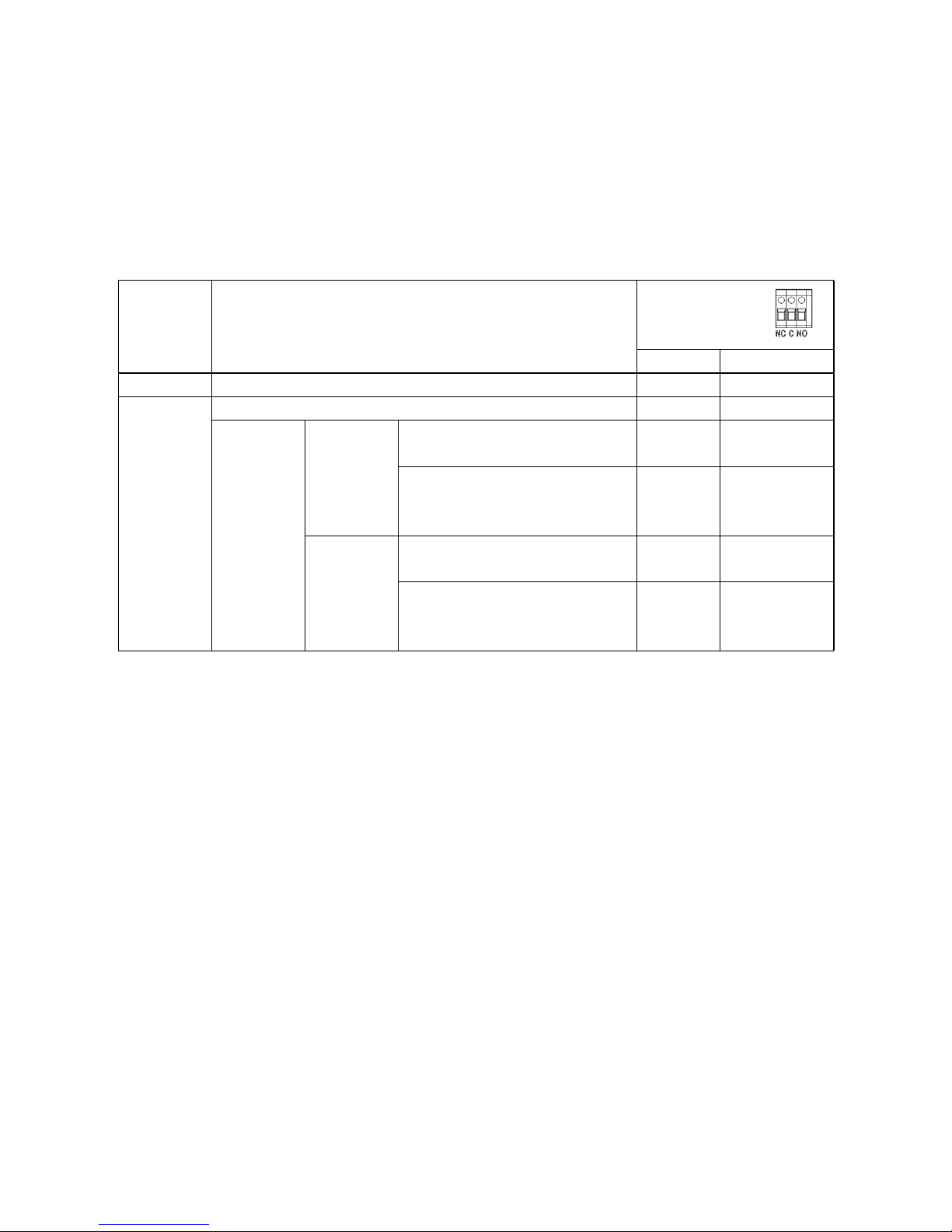
Dry Contact Signal
There is one dry contact (3A/250VAC) available on the rear panel. It could be used to deliver signal to external
device when battery voltage reaches warning level.
10
Unit Status
Condition
Dry contact port:
NC & C NO & C
Power Off Unit is off and no output is powered. Close Open
Power On
Output is powered from Utility. Close Open
Output is
powered
from
Battery or
Solar.
Program 01
set as Utility
Battery voltage < Low DC warning
voltage
Open
Close
Battery voltage > Setting value in
Program 13 or battery charging
reaches floating stage
Close
Open
Program 01
is set as
SBU or
Solar first
Battery voltage < Setting value in
Program 12
Open
Close
Battery voltage > Setting value in
Program 13 or battery charging
reaches floating stage
Close
Open
Page 13
OPERATION
Power ON/OFF
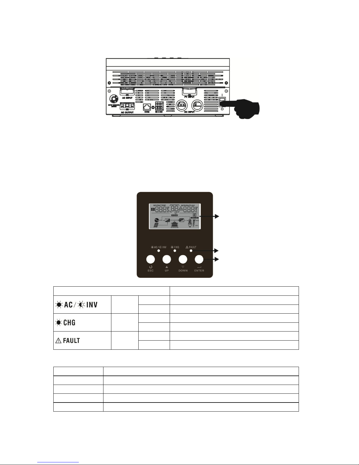
Once the unit has been properly installed and the batteries are connected well, simply press On/Off switch
(located on the button of the case) to turn on the unit.
Operation and Display Panel
The operation and display panel, shown in below chart, is on the front panel of the inverter. It includes
three indicators, four function keys and a LCD display, indicating the operating status and input/output
power information.
LCD display
LED indicators
Function keys
LED Indicator
Function Keys
11
Function Key Description
ESC To exit setting mode
UP To go to previous selection
DOWN To go to next selection
ENTER To confirm the selection in setting mode or enter setting mode
LED Indicator Messages
Green
Solid On Output is powered by utility in Line mode.
Flashing Output is powered by battery or PV in battery mode.
Green
Solid On Battery is fully charged.
Flashing Battery is charging.
Red
Solid On Fault occurs in the inverter.
Flashing Warning condition occurs in the inverter.
Page 14
LCD Display Icons
12
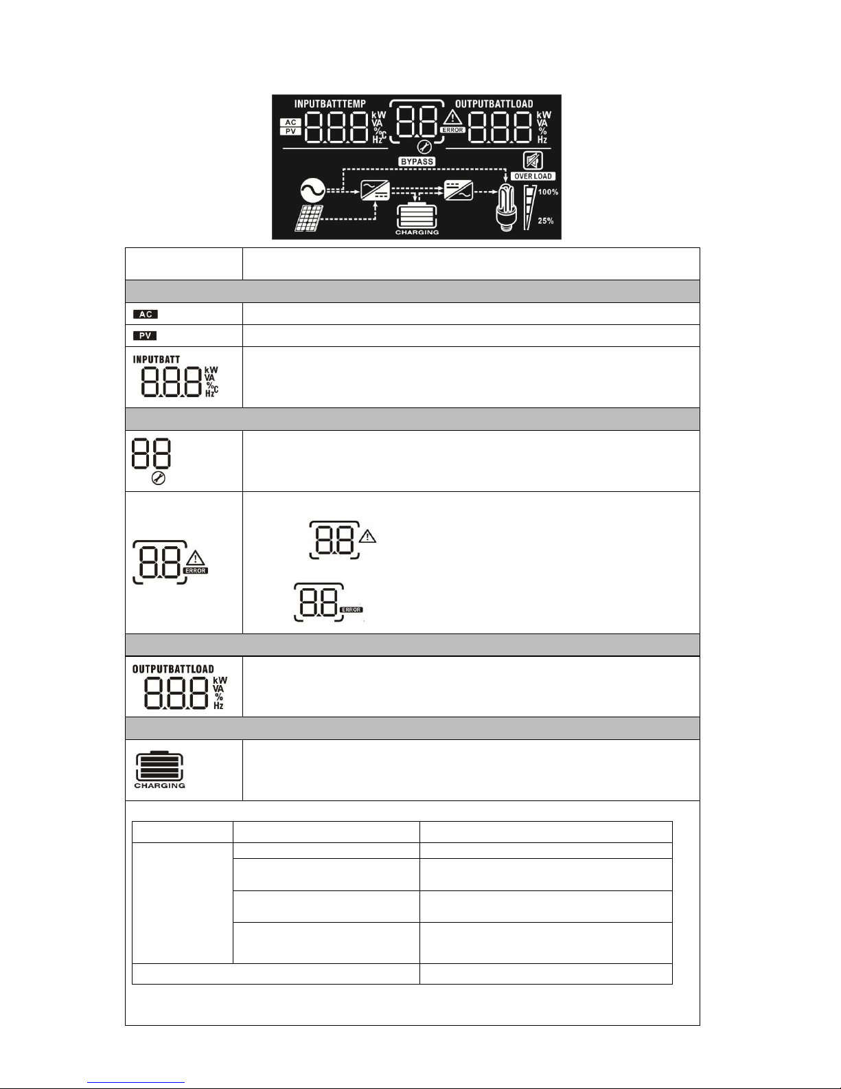
Icon
Function description
Input Source Information
Indicates the AC input.
Indicates the PV input
Indicate input voltage, input frequency, PV voltage, battery voltage and
charger current.
Configuration Program and Fault Information
Indicates the setting programs.
Indicates the warning and fault codes.
Warning: flashing with warning code.
Fault: lighting with fault code
Output Information
Indicate output voltage, output frequency, load percent, load in VA, load in
Watt and discharging current.
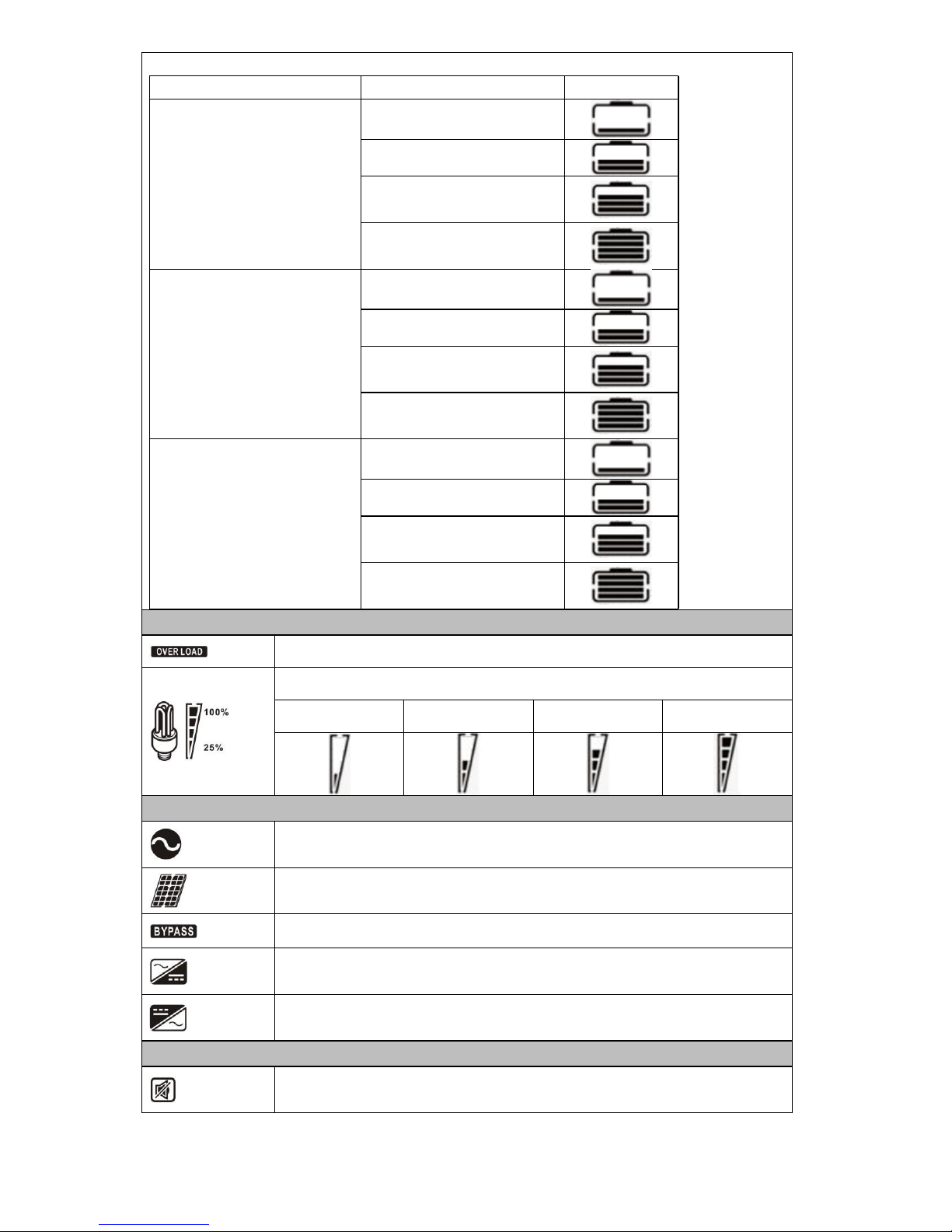
Battery Information
Indicates battery level by 0-24%, 25-49%, 50-74% and 75-100% in battery
mode and charging status in line mode.
In AC mode, it will present battery charging status.
bars will flash in turns.
two bars will flash in turns.
Status Battery voltage LCD Display
Constant
Current mode /
Constant
Voltage mode
<2V/cell 4 bars will flash in turns.
2 ~ 2.083V/cell
Bottom bar will be on and the other three
2.083 ~ 2.167V/cell
Bottom two bars will be on and the other
> 2.167 V/cell
Bottom three bars will be on and the top
bar will flash.
Floating mode. Batteries are fully charged. 4 bars will be on.
Page 15
13
In battery mode, it will present battery capacity.
Load Percentage Battery Voltage LCD Display
Load >50%
< 1.717V/cell
1.717V/cell ~ 1.8V/cell
1.8 ~ 1.883V/cell
> 1.883 V/cell
50%> Load > 20%
< 1.817V/cell
1.817V/cell ~ 1.9V/cell
1.9 ~ 1.983V/cell
> 1.983
Load < 20%
< 1.867V/cell
1.867V/cell ~ 1.95V/cell
1.95 ~ 2.033V/cell
> 2.033
Load Information
Indicates overload.
Indicates the load level by 0-24%, 25-50%, 50-74% and 75-100%.
0%~25% 25%~50% 50%~75% 75%~100%
Mode Operation Information
Indicates unit connects to the mains.
Indicates unit connects to the PV panel.
Indicates load is supplied by utility power.
Indicates the utility charger circuit is working.
Indicates the DC/AC inverter circuit is working.
Mute Operation
Indicates unit alarm is disabled.
Page 16
LCD Setting
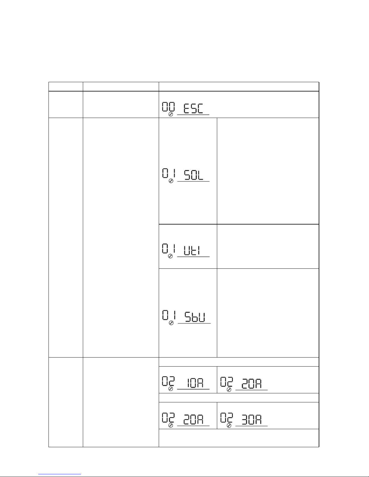
After pressing and holding ENTER button for 3 seconds, the unit will enter setting mode. Press “UP” or “DOWN”
button to select setting programs. And then, press “ENTER” button to confirm the selection or ESC button to
exit.
Setting Programs:
14
Program Description Selectable option
00
Exit setting mode
Escape
01
Output source priority:
To configure load power
source priority
Solar first
Solar energy provides power to the
loads as first priority.
If solar energy is not sufficient to
power all connected loads, battery
energy will supply power the loads at
the same time.
Utility provides power to the loads only
when any one condition happens:
- Solar energy is not available
- Battery voltage drops to either
low-level warning voltage or the
setting point in program 12.
Utility first (default)
Utility will provide power to the loads
as first priority.
Solar and battery energy will provide
power to the loads only when utility
power is not available.
SBU priority
Solar energy provides power to the
loads as first priority.
If solar energy is not sufficient to
power all connected loads, battery
energy will supply power to the loads
at the same time.
Utility provides power to the loads only
when battery voltage drops to either
low-level warning voltage or the
setting point in program 12.
02
Maximum charging current:
To configure total charging
current for solar and utility
chargers.
(Max. charging current =
utility charging current +
solar charging current)
Available options in 1KVA 24V and 1KVA/3KVA 48V models:
10A 20A (default)
Available options in 2-3KVA 24V models:
20A 30A (default)
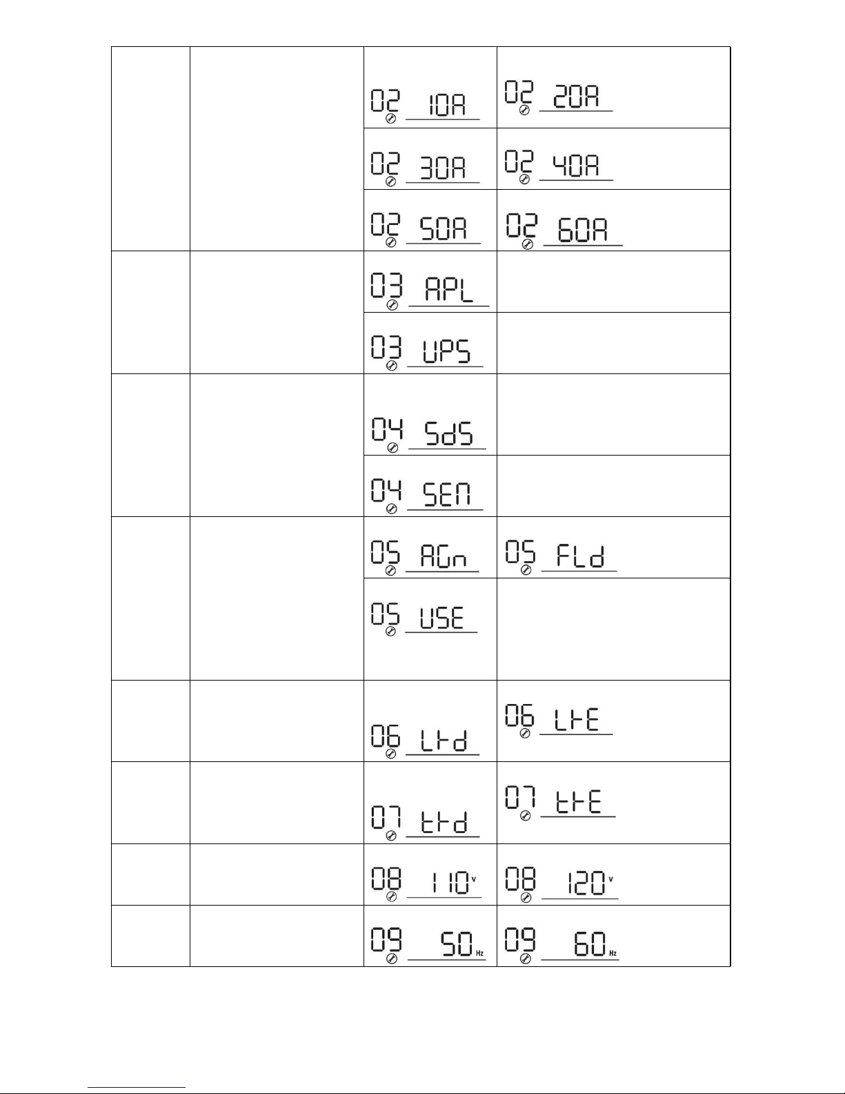
Available options in 2-3KVA 24V/48V Plus and 4-5KVA 48V
models:
Page 17
enable/disable
15
10A (Not available
for 2-3KVA 24V Plus)
20A
30A 40A
50A 60A (default)
03
AC input voltage range
Appliances (default)
If selected, acceptable AC input
voltage range will be within
90-280VAC.
UPS
If selected, acceptable AC input
voltage range will be within
170-280VAC.
04
Power saving mode
Saving mode disable
(default)
If disabled, no matter connected load
is low or high, the on/off status of
inverter output will not be effected.
Saving mode enable
If enabled, the output of inverter will
be off when connected load is pretty
low or not detected.
05
Battery type
AGM (default) Flooded
User-Defined
If “User-Defined” is selected, battery
charge voltage and low DC cut-off
voltage can be set up in program 26,
27 and 29.
06
Auto restart when overload
occurs
Restart disable
(default)
Restart enable
07
Auto restart when over
temperature occurs
Restart disable
(default)
Restart enable
08
Output voltage (only
available for 120Vac
models)
110V 120V (default)
09
Output frequency
50Hz (default) 60Hz
Page 18
16
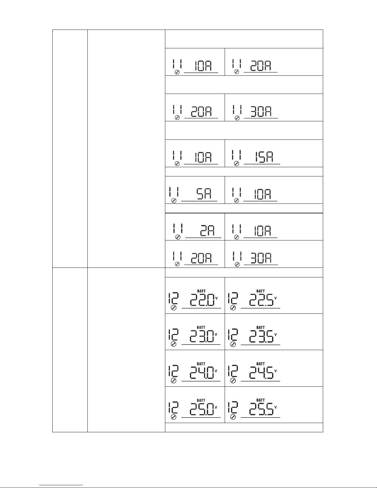
11
Maximum utility charging
current
Available options in 1KVA 24V and 2KVA 24V Plus 120Vac
model:
10A 20A(default):
Available options in 2-3KVA 24V and 2-3KVA 24V Plus
models:
20A 30A (default)
Available options in 1KVA/3KVA 48V and 2-3KVA 48V Plus
models:
10A 15A(default):
Available options in 2KVA 48V Plus 120Vac model:
5A 10A(default)
Available options in 4KVA/5KVA 48V models:
2A 10A
20A 30A (default)
12
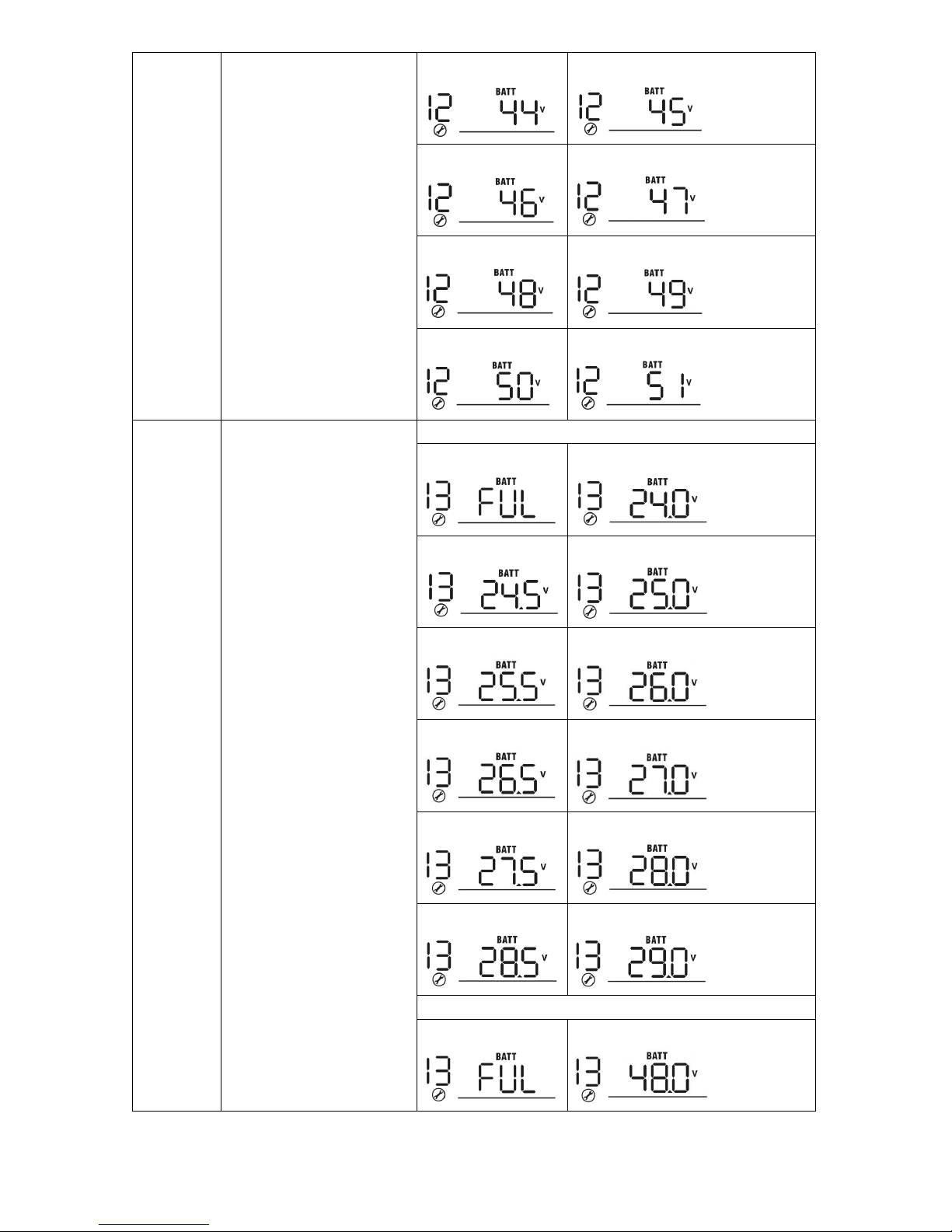
Setting voltage point back
to utility source when
selecting “SBU priority” or
“Solar first” in program 01.
Available options in 24V models:
22.0V 22.5V
23.0V (default) 23.5V
24.0V 24.5V
25.0V 25.5V
Available options in 48V models:
Page 19
selecting “SBU priority” or
17
44V 45V
46V (default) 47V
48V 49V
50V 51V
13
Setting voltage point back
to battery mode when
“Solar first” in program 01.
Available options in 24V models:
Battery fully charged 24V
24.5V 25V
25.5V 26V
26.5V 27V (default)
27.5V 28V
28.5V 29V
Available options in 48V models:
Battery fully charged 48V
Page 20
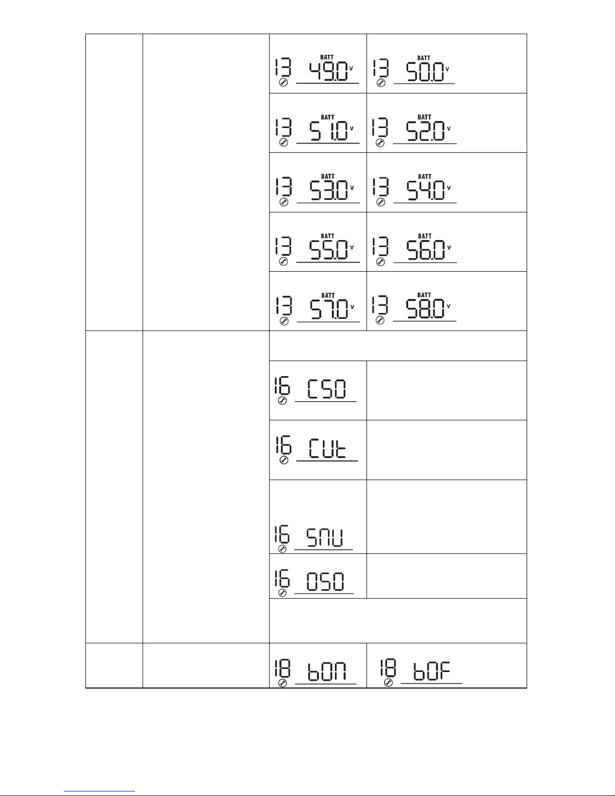
18
49V 50V
51V 52V
53V 54V (default)
55V 56V
57V 58V
16
Charger source priority:
To configure charger source
priority
If this inverter/charger is working in Line, Standby or Fault
mode, charger source can be programmed as below:
Solar first
Solar energy will charge battery as
first priority.
Utility will charge battery only when
solar energy is not available.
Utility first
Utility will charge battery as first
priority.
Solar energy will charge battery only
when utility power is not available.
Solar and Utility
(Only available for
4KVA/5KVA model)
Solar energy and utility will charge
battery at the same time.
Only Solar
Solar energy will be the only charger
source no matter utility is available
or not.
If this inverter/charger is working in Battery mode or Power
saving mode, only solar energy can charge battery. Solar
energy will charge battery if it's available and sufficient.
18
Alarm control
Alarm on (default) Alarm off
Page 21
is interrupted
(C.V voltage)
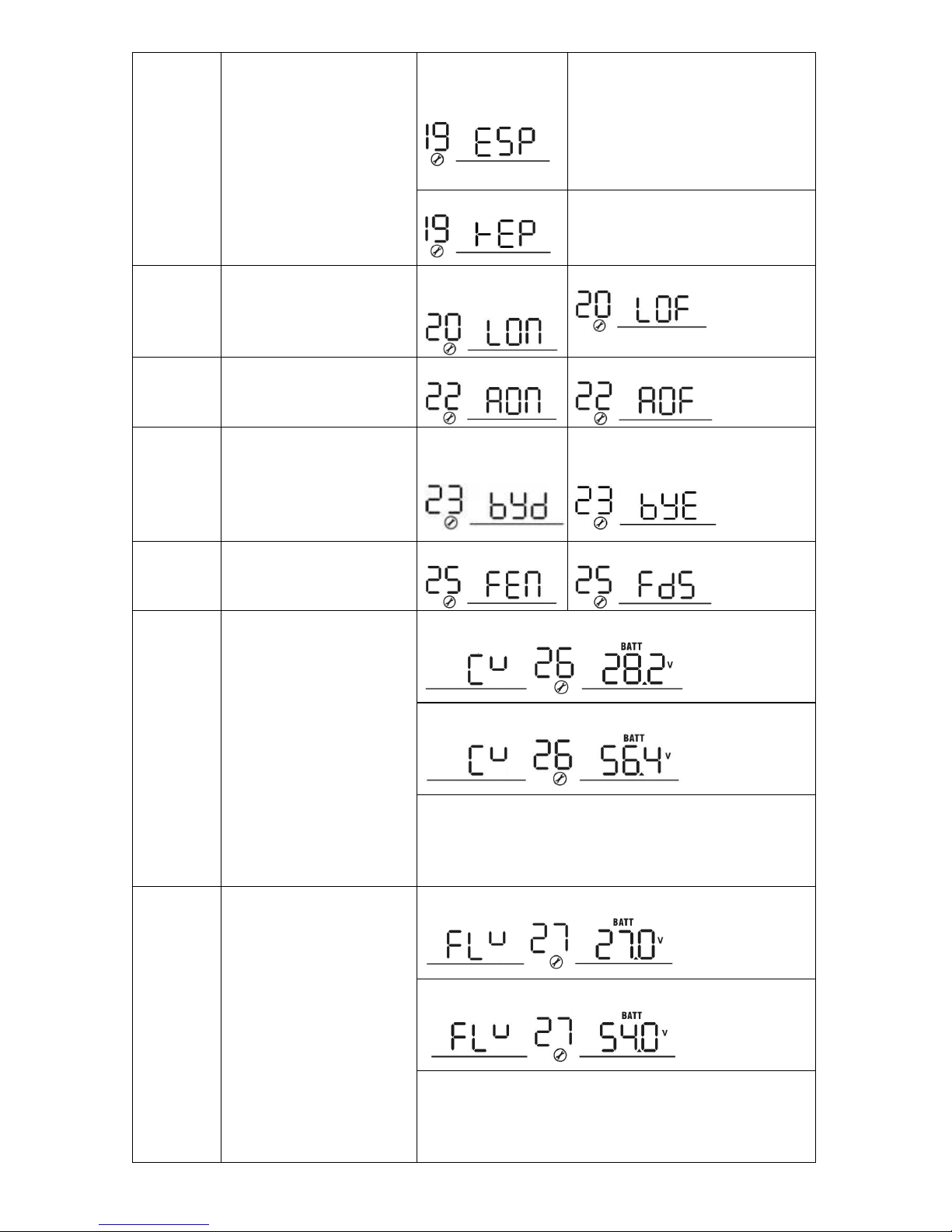
19
19
Auto return to default
display screen
Return to default
display screen
(default)
If selected, no matter how users
switch display screen, it will
automatically return to default
display screen (Input voltage
/output voltage) after no button is
pressed for 1 minute.
Stay at latest screen
If selected, the display screen will
stay at latest screen user finally
switches.
20
Backlight control
Backlight on
(default)
Backlight off
22
Beeps while primary source
Alarm on (default) Alarm off
23
Overload bypass:
When enabled, the unit will
transfer to line mode if
overload occurs in battery
mode.
Bypass disable
(default)
Bypass enable
25
Record Fault code
Record enable Record disable (default)
26
Bulk charging voltage
24V model default setting: 28.2V
48V model default setting: 56.4V
If self-defined is selected in program 5, this program can be
set up. Setting range is from 24.0V to 29.2V for 24V model
and 48.0V to 58.4V for 48V model. Increment of each click
is 0.1V.
27
Floating charging voltage
24V model default to 27.0V
48V model default setting: 54.0V
If self-defined is selected in program 5, this program can be
set up. Setting range is from 24.0V to 29.2V for 24V model,
48.0V to 58.4V for 48V model. Increment of each click is
0.1V.
Page 22
according to the following
battery charging power no
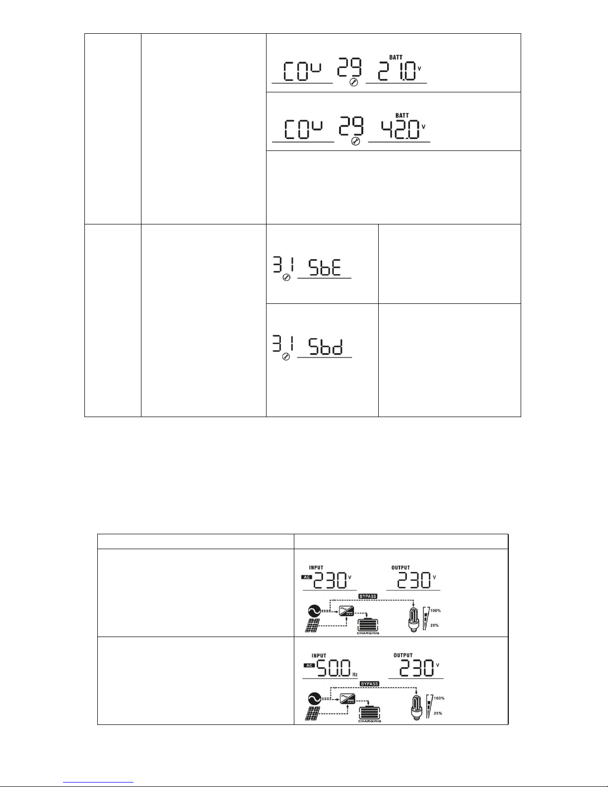
Display Setting
The LCD display information will be switched in turns by pressing “UP” or “DOWN” key. The selectable
information is switched as below order: input voltage, input frequency, PV voltage, MPPT charging current,
MPPT charging power, battery voltage, output voltage, output frequency, load percentage, load in VA,
load in Watt, DC discharging current, main CPU Version and second CPU Version.
20
Selectable information LCD display
Input voltage/Output voltage
(Default Display Screen)
Input Voltage=230V, output voltage=230V
Input frequency
Input frequency=50Hz
29
Low DC cut-off voltage
24V model default setting: 21.0V
48V model default setting: 42.0V
If self-defined is selected in program 5, this program can be
set up. Setting range is from 20.0V to 24.0V for 24V model,
40.0V to 48.0V for 48V model. Increment of each click is
0.1V. Low DC cut-off voltage will be fixed to setting value no
matter what percentage of load is connected.
31
Solar power balance: When
enabled, solar input power
will be automatically
adjusted according to
connected load power.
(Only available for
4KVA/5KVA model)
Solar power balance
enable (Default):
If selected, solar input power
will be automatically adjusted
formula:
Max. input solar power = Max.
battery charging power +
Connected load power.
Solar power balance
disable:
If selected, the solar input
power will be the same to max.
matter how much loads are
connected. The max. battery
charging power will be based on
the setting current in program
02.
(Max. solar power = Max.
battery charging power)
Page 23
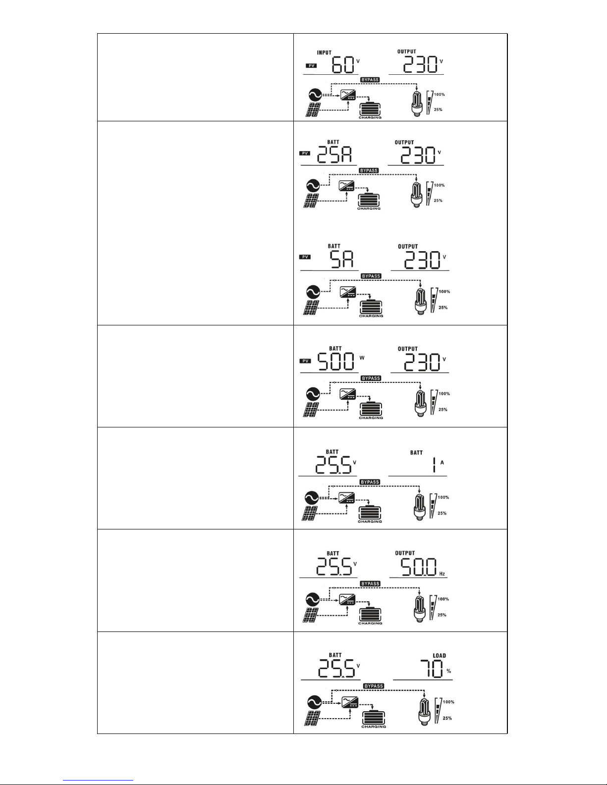
21
PV voltage
PV voltage=60V
MPPT Charging current
Current ≧10A
Current < 10A
MPPT Charging power MPPT charging power=500W
Battery voltage/ DC discharging current
Battery voltage=25.5V, discharging current=1A
Output frequency
Output frequency=50Hz
Load percentage
Load percent=70%
Page 24
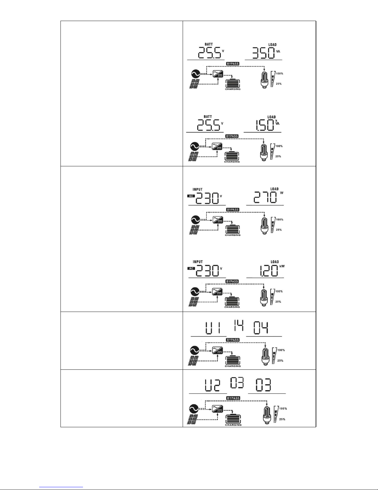
22
Load in VA
When connected load is lower than 1kVA, load in
VA will present xxxVA like below chart.
When load is larger than 1kVA (≧1KVA), load in
VA will present x.xkVA like below chart.
Load in Watt
When load is lower than 1kW, load in W will
present xxxW like below chart.
When load is larger than 1kW (≧1KW), load in W
will present x.xkW like below chart.
Main CPU version checking
Main CPU version 00014.04
Secondary CPU version checking
Secondary CPU version 00003.03
Page 25
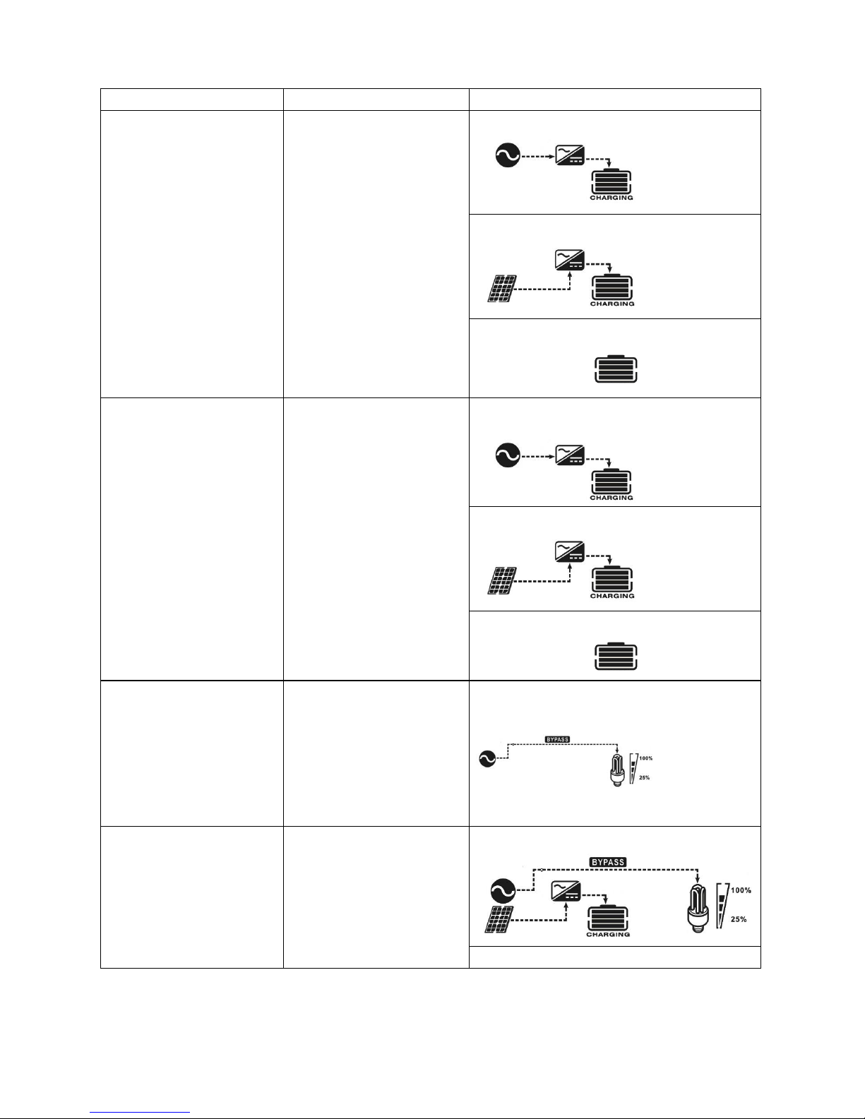
Operating Mode Description
23
Operation mode Description LCD display
Standby mode / Power
saving mode
Note:
*Standby mode: The inverter is
not turned on yet but at this
time, the inverter can charge
battery without AC output.
*Power saving mode: If
enabled, the output of inverter
will be off when connected load
is pretty low or not detected.
No output is supplied by the
unit but it still can charge
batteries.
Charging by utility.
Charging by PV energy.
No charging.
Fault mode
Note:
*Fault mode: Errors are caused
by inside circuit error or external
reasons such as over
temperature, output short
circuited and so on.
PV energy and utility can
charge batteries.
Charging by utility. (Only available in 1K/2K/3K
model)
Charging by PV energy.
No charging.
Fault mode
Note:
*Fault mode: Errors are caused
by inside circuit error or external
reasons such as over
temperature, output short
circuited and so on.
Utility can power loads when
the unit starts up without
battery. (Only available in
4K/5K model with single
operation)
Power from utility
Line Mode
The unit will provide output
power from the mains. It will
also charge the battery at
line mode.
Charging by PV energy
Charging by utility.
Page 26
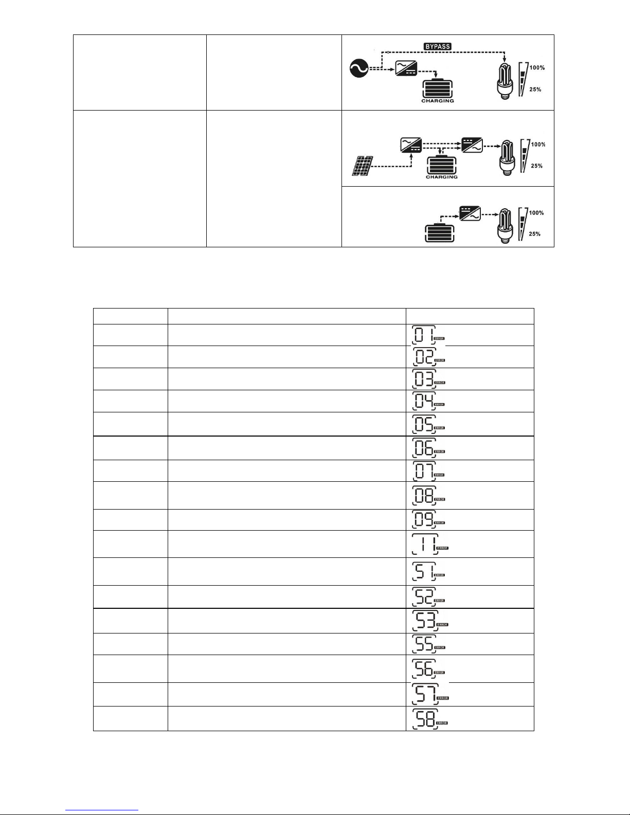
Fault Reference Code
by internal converter components.
Output voltage is too high. (For 4K/5K model)
NOTE: Fault codes 51, 52, 53, 55, 56, 57 and 58 are only available in 4K/5K model.
24
Fault Code Fault Event Icon on
01
Fan is locked when inverter is off.
02
Over temperature
03
Battery voltage is too high
04
Battery voltage is too low
05
Output short circuited or over temperature is detected
06
Output voltage is abnormal. (For 1K/2K/3K model)
07
Overload time out
08
Bus voltage is too high
09 Bus soft start failed
11
Main relay failed
51
Over current or surge
52
Bus voltage is too low
53
Inverter soft start failed
55
Over DC voltage in AC output
56
Battery connection is open
57
Current sensor failed
58
Output voltage is too low
Battery Mode
The unit will provide output
power from battery and PV
power.
Power from battery and PV energy.
Power from battery only.
Page 27
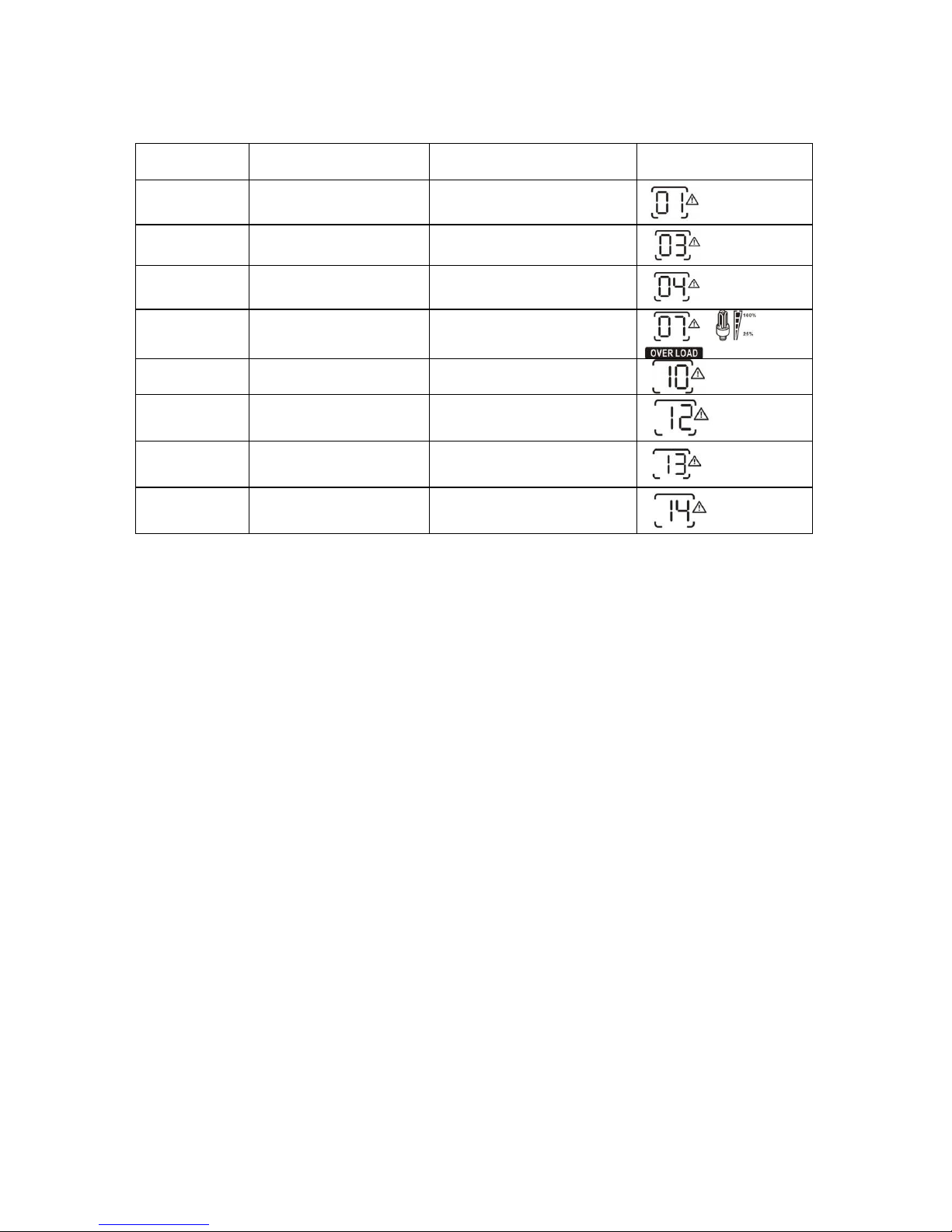
Warning Indicator
second
25
Warning
Code
Warning Event
Audible Alarm
Icon flashing
01
Fan is locked when
inverter is on.
Beep three times every
03
Battery is over-charged Beep once every second
04
Low battery
Beep once every second
07
Overload
Beep once every 0.5 second
10
Output power derating Beep twice every 3 seconds
12
Solar charger stops due
to low battery.
13
Solar charger stops due
to high PV voltage.
14
Solar charger stops due
to overload.
Page 28
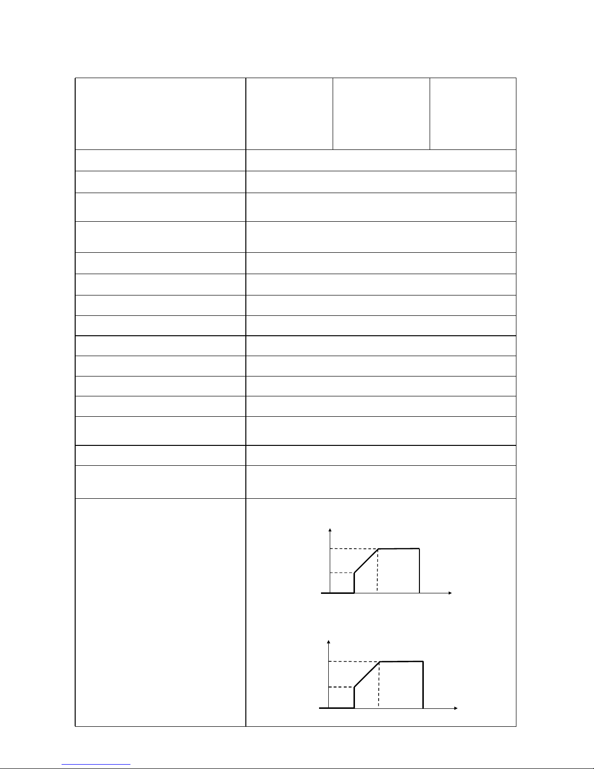
SPECIFICATIONS
Table 1 Line Mode Specifications
26
INVERTER MODEL
1KVA 24V
2KVA 24V
3KVA 24V
1KVA 48V
3KVA 48V
2KVA 24V Plus
3KVA 24V Plus
2KVA 48V Plus
3KVA 48V Plus
4KVA
5KVA
Input Voltage Waveform
Sinusoidal (utility or generator)
Nominal Input Voltage
120Vac or 230Vac
Low Loss Voltage
95Vac±7V or 170Vac±7V (UPS)
65Vac±7V or 90Vac±7V (Appliances)
Low Loss Return Voltage
100Vac±7V or 180Vac±7V (UPS);
70Vac±7V or 100Vac±7V (Appliances)
High Loss Voltage
140Vac±7V or 280Vac±7V
High Loss Return Voltage
135Vac±7V or 270Vac±7V
Max AC Input Voltage 150Vac or 300Vac
Nominal Input Frequency 50Hz / 60Hz (Auto detection)
Low Loss Frequency 40±1Hz
Low Loss Return Frequency 42±1Hz
High Loss Frequency 65±1Hz
High Loss Return Frequency
63±1Hz
Output Short Circuit Protection
Line mode: Circuit Breaker
Battery mode: Electronic Circuits
Efficiency (Line Mode) >95% ( Rated R load, battery full charged )
Transfer Time
10ms typical (UPS);
20ms typical (Appliances)
Output power derating:
When AC input voltage drops to 95V or
170V depending on models, the output
power will be derated.
120Vac model:
Output Power
Rated Power
50% Power
65V 95V
140V
Input Voltage
230Vac model:
Output Power
Rated Power
50%
Power
90V 170V
280V
Input Voltage
Page 29
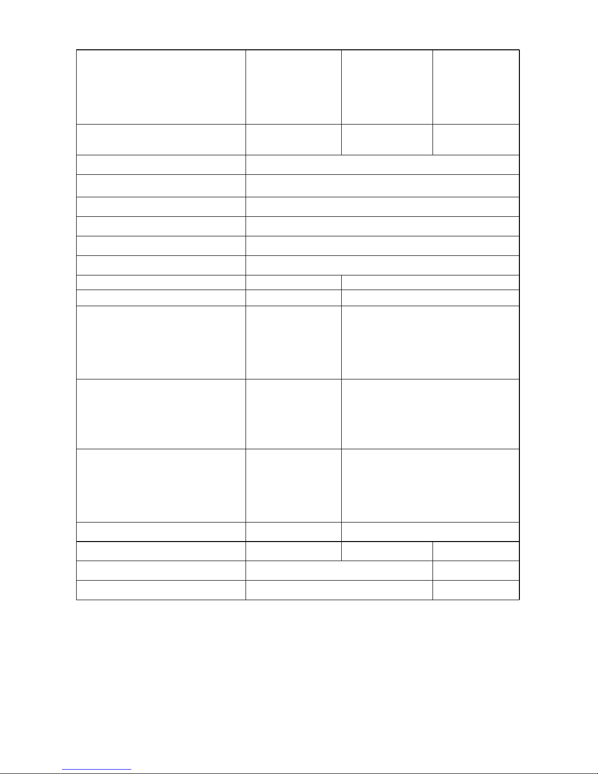
Table 2 Inverter Mode Specifications
5KVA/4KW
27
INVERTER MODEL
1KVA 24V
2KVA 24V
3KVA 24V
2KVA 24V Plus
3KVA 24V Plus
1KVA 48V
3KVA 48V
2KVA 48V Plus
3KVA 48V Plus
4KVA
5KVA
Rated Output Power
1KVA/0.8KW
2KVA/1.6KW
3KVA/2.4KW
1KVA/1KW
2KVA/1.6KW
3KVA/2.4KW
4KVA/3.2KW
Output Voltage Waveform Pure Sine Wave
Output Voltage Regulation
110/120VAC±5% or 230Vac±5%
Output Frequency 60Hz or 50Hz
Peak Efficiency 90%
Overload Protection 5s@≥150% load; 10s@110%~150% load
Surge Capacity 2* rated power for 5 seconds
Nominal DC Input Voltage 24Vdc 48Vdc
Cold Start Voltage 23.0Vdc 46.0Vdc
Low DC Warning Voltage
@ load < 20%
@ 20% ≤ load < 50%
@ load ≥ 50%
22.0Vdc
21.4Vdc
20.2Vdc
44.0Vdc
42.8Vdc
40.4Vdc
Low DC Warning Return Voltage
@ load < 20%
@ 20% ≤ load < 50%
@ load ≥ 50%
23.0Vdc
22.4Vdc
21.2Vdc
46.0Vdc
44.8Vdc
42.4Vdc
Low DC Cut-off Voltage
@ load < 20%
@ 20% ≤ load < 50%
@ load ≥ 50%
21.0Vdc
20.4Vdc
19.2Vdc
42.0Vdc
40.8Vdc
38.4Vdc
High DC Recovery Voltage 29Vdc 58Vdc
High DC Cut-off Voltage 31Vdc 62Vdc 60Vdc
No Load Power Consumption <25W <50W
Saving Mode Power Consumption <10W <15W
Page 30
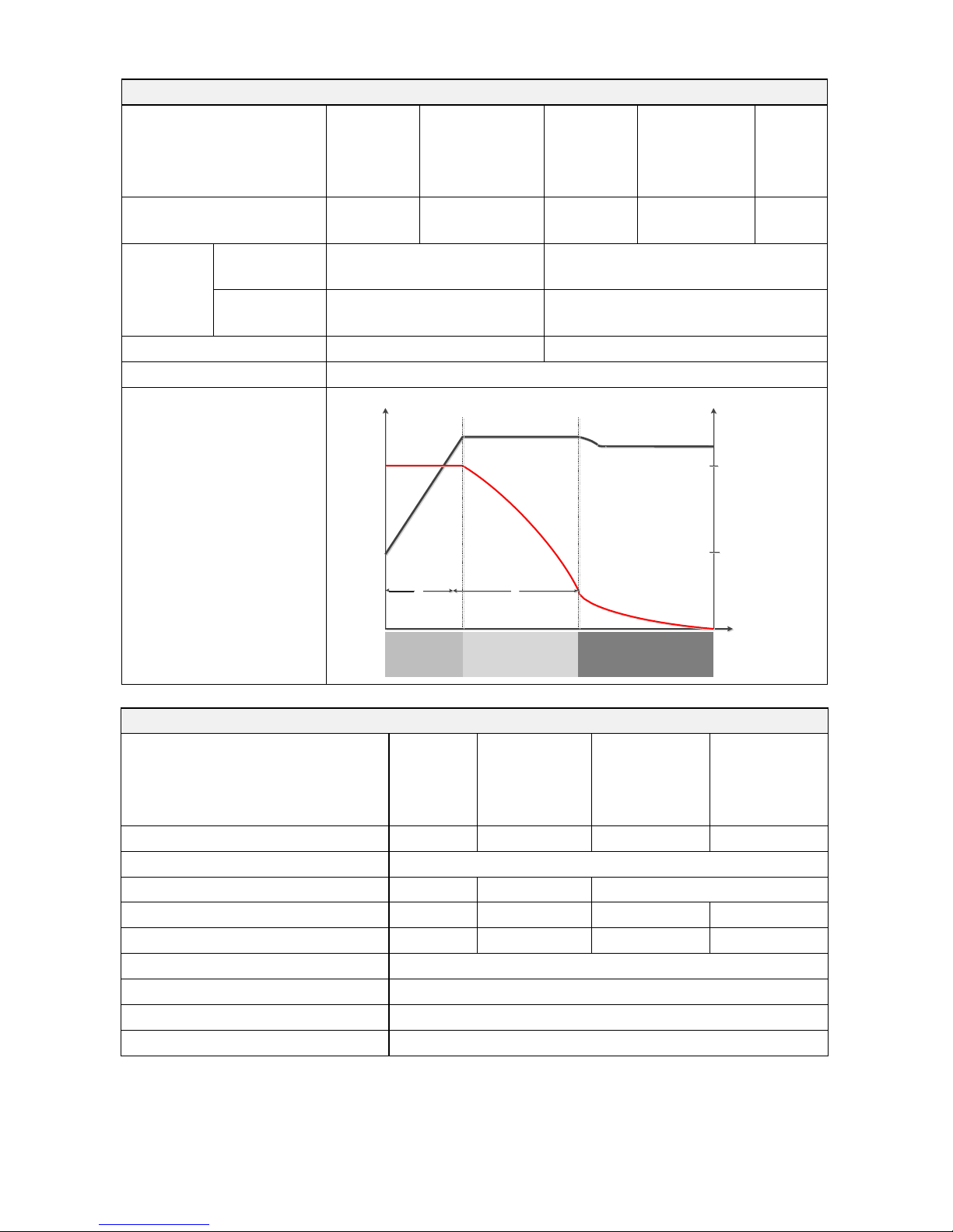
Table 3 Charge Mode Specifications
2.25Vd c
28
Solar Charging Mode
INVERTER MODEL
1KVA 24V
2KVA 24V
3KVA 24V
1KVA 48V
3KVA 48V
2KVA 24V Plus
3KVA 24V Plus
2KVA 48V Plus
3KVA 48V Plus
4KVA
5KVA
Rated Power 600W 900W 1500W 3000W
Efficiency 98.0% max.
Max. PV Array Open Circuit Voltage 75Vdc max 102Vdc max 145Vdc
PV Array MPPT Voltage Range 30~66Vdc 60~88Vdc 30~115Vdc 60~115Vdc
Min battery voltage for PV charge 17Vdc 34Vdc 17Vdc 34Vdc
Standby Power Consumption 2W
Battery Voltage Accuracy +/-0.3%
PV Voltage Accuracy +/-2V
Charging Algorithm 3-Step
Utility Charging Mode
INVERTER MODEL
1KVA 24V
2KVA 24V
Plus 120Vac
2KVA 24V
3KVA 24V
2KVA 24V Plus
3KVA 24V Plus
2KVA 48V
Plus 120Vac
1KVA 48V
3KVA 48V
2KVA 48V Plus
3KVA 48V Plus
4KVA
5KVA
Charging Current (UPS)
@ Nominal Input Voltage
10/20A
20/30A
5/10A
10/15A
2/10A
20/30A
Bulk
Charging
Voltage
Flooded
Battery
29.2
58.4
AGM / Gel
Battery
28.2
56.4
Floating Charging Voltage 27Vdc 54Vdc
Charging Algorithm 3-Step
Charging Curve
Battery Voltage, per cell
Charging Current, %
2.43Vdc (2.35Vdc )
100%
50%
T0 T1
me
Voltage
Current
T1 = 10* T0, minimum 10mins, maximum 8hrs
Bulk
(Constant Current)
Absorption
(Constant Voltage)
Maintenance
(Floating)
Ti
Page 31
Table 4 General Specifications
29
INVERTER MODEL
1KVA 24V
1KVA 48V
2KVA 24V
3KVA 24V
3KVA 48V
2KVA 24V Plus
3KVA 24V Plus
2KVA 48V Plus
3KVA 48V Plus
4KVA 5KVA
Safety Certification CE
Operating Temperature
Range
0°C to 55°C
Storage temperature -15°C~ 60°C
Dimension (D*W*H), mm 128 x 272 x 355 140 x 295 x 479 140 x295 x540
Net Weight, kg 7.4 7.6 8.0 11.5 12.5 13.5
Page 32
TROUBLE SHOOTING
2. Re-charge battery.
and AC wiring is connected
thin and/or too long.
applied) is working well or if
to Utility first.
connected well.
switching off some
the unit is blocked or whether
component is over 100°C.
batteries are meet
well, please return to repair
30
Problem LCD/LED/Buzzer Explanation / Possible cause What to do
Unit shuts down
automatically
during startup
process.
LCD/LEDs and buzzer
will be active for 3
seconds and then
complete off.
The battery voltage is too low
(<1.91V/Cell)
1. Re-charge battery.
2. Replace battery.
No response after
power on.
No indication.
1. The battery voltage is far too
low. (<1.4V/Cell)
2. Battery polarity is connected
reversed.
1. Check if batteries and the
wiring are connected well.
3. Replace battery.
Mains exist but the
unit works in
battery mode.
Input voltage is
displayed as 0 on the
LCD and green LED is
flashing.
Input protector is tripped
Check if AC breaker is tripped
well.
Green LED is flashing.
Insufficient quality of AC power.
(Shore or Generator)
1. Check if AC wires are too
2. Check if generator (if
input voltage range setting is
correct. (UPSAppliance)
Green LED is flashing.
Set “Solar First” as the priority of
output source.
Change output source priority
When the unit is
turned on, internal
relay is switched on
and off repeatedly.
LCD display and LEDs
are flashing
Battery is disconnected.
Check if battery wires are
Buzzer beeps
continuously and
red LED is on.
Fault code 07
Overload error. The inverter is
overload 110% and time is up.
Reduce the connected load by
equipment.
Fault code 05
Output short circuited.
Check if wiring is connected
well and remove abnormal
load.
Temperature of internal converter
component is over 120°C. (Only
available for 1-3KVA models.)
Check whether the air flow of
the ambient temperature is
too high.
Fault code 02
Internal temperature of inverter
Fault code 03
Battery is over-charged. Return to repair center.
The battery voltage is too high.
Check if spec and quantity of
requirements.
Fault code 01 Fan fault Replace the fan.
Fault code 06/58
Output abnormal (Inverter voltage
below than 190Vac or is higher
than 260Vac)
1. Reduce the connected
load.
2. Return to repair center
Fault code
08/09/53/57
Internal components failed.
Return to repair center.
Fault code 51 Over current or surge.
Restart the unit, if the error
happens again, please return
to repair center.
Fault code 52 Bus voltage is too low.
Fault code 55 Output voltage is unbalanced.
Fault code 56
Battery is not connected well or
fuse is burnt.
If the battery is connected
center.
Page 33
Appendix: Approximate Back-up Time Table
31
Model Load (VA) Backup Time @ 48Vdc 100Ah (min) Backup Time @ 48Vdc 200Ah (min)
1KVA
100 2529 5058
200 1264 2529
300 843 1686
400 608 1279
500 482 1035
600 406 872
700 310 710
800 268 615
900 231 540
1000 186 471
Model Load (VA) Backup Time @24Vdc 100Ah (min) Backup Time @24Vdc 200Ah (min)
1KVA
200 766 1610
400 335 766
600 198 503
800 139 339
1000 112 269
2KVA
200 766 1610
400 335 766
600 198 503
800 139 339
1000 112 269
1200 95 227
1400 81 176
1600 62 140
1800 55 125
2000 50 112
3KVA
300 449 1100
600 222 525
900 124 303
1200 95 227
1500 68 164
1800 56 126
2100 48 108
2400 35 94
2700 31 74
3000 28 67
Page 34
Note: Backup time depends on the quality of the battery, age of battery and type of battery.
Specifications of batteries may vary depending on different manufacturers.
32
Model Load (VA) Backup Time @ 48Vdc 100Ah (min) Backup Time @ 48Vdc 200Ah (min)
2KVA
200 1581 3161
400 751 1581
600 491 1054
800 331 760
1000 268 615
1200 221 508
1400 172 387
1600 136 335
1800 120 295
2000 106 257
3KVA
300 1054 2107
600 491 1054
900 291 668
1200 196 497
1500 159 402
1800 123 301
2100 105 253
2400 91 219
2700 71 174
3000 63 155
4KVA
400 766 1610
800 335 766
1200 198 503
1600 139 339
2000 112 269
2400 95 227
2800 81 176
3200 62 140
3600 55 125
4000 50 112
5KVA
500 613 1288
1000 268 613
1500 158 402
2000 111 271
2500 90 215
3000 76 182
3500 65 141
4000 50 112
4500 44 100
5000 40 90
 Loading...