

Page 1
R-4 Bulldozer user’s Manual
G.M.Corporation co.,Ltd.
12th, Daeyoung B/D, 44-1, Yoido-Dong,
Youngdeungpo-gu, Seoul, Korea
Tel : 82-2-761-9594 Fax : 82-2-761-9585
E-mail : gmcsales@gmc.co.kr
www.gmc.co.kr
Page 2
Welcome!
G.M.Corporation Ltd is a manufacturer and distributor
headquartered in Seoul, Korea and founded in 1996.
The company offers a wide range of PC cases, Power
supplies, Computer peripheral and service to
customers worldwide.
It is G.M.Corporation’s mission to be the best provider
of the state-of-the-art products in the global market.
By offering superior products and complete service,
the company seeks to share the enjoyable computer
life for worldwide end users.
Through the constant invention and innovation,
G.M.Corporation has achieved a number of patents
for its products. As a result of being acknowledged
for sincere effort in research and development,
G.M.Corporation received a good venture company
certification from the Korean Business Administration
in 2001.
G.M.Corporation produces middle tower PC cases
and HTPC cases (Home Theater PC) which supports
mATX and ATX form factors. Our HTPC has a
fantastic design and functions and supports up to MS
Windows VISTA and MCE (Media Center Edition).
In an ever-changing business environment,
G.M.Corporation continues to be committed to
customer satisfaction with high quality and innovative
design. G.M.Corporation is devoted to develop
superior goods and become a leading computer case
supplier in Korea.
Thank you for your concern and support.
Contents
Chapter 1. Product Introduction
1.1 Specification
1.2 Features & Benefit
1.3 Case Overview
Chapter 2. Installation
2.1 Side Panel Removal
2.2 HDD Installation
2.3 ODD Installation
2.4 Power Supply, M/B, Graphic Card Installation
2.5 Air Filter
2.6 Bottom Fan Hole
2.7 Case LED & Switch Connections
2.8 Connecting FPIO to Mainboard
2.9 Front thermometer power cable connection
2.10 Side thermometer power cable connection
2.11 Side fan cable connection
Page 3
Chapter 1. Product Introduction
1.1 Specification
•
Dimension (W x D x H)
•
M/B Form Factor
•
Drive Bay
Expansion Slot
•
•
Cooling Fan
Temperature
•
•
Front Panel I/O
: 5.25” x 1(Ext)
3.5” x 2(Int)
: ATX
: 7 Slots
: Front – 92mm LED Fan x 1
Rear – 120mm Fan x 1
Side cover - 80mm Fan x 1
Bottom – 80mm Fan x 1 (Optional)
: Front x 1, Side panel x 1
: USB x 2port
Audio port(HD Audio, AC 97)
: 180 x 290 x 420mm
1.2 Features & Benefit
Middle Tower ATX Case
▪ Innovative & Unique Design
▪ Efficient Internal Structure
▪ Support Full ATX
▪ Support largest graphic cards
▪ Support 7 expansion slots
Front Panel Function
▪Word’s first patented vertical ODD
▪Tuning effect with front LED Fan
▪ Easy removal of ODD cover
Excellent Thermal Solution
▪ Includes 1 x 120mm fan on the back
▪ Includes 1 x 92mm LED front fan
▪ Dynamic Side design with additional 1 x 80mm fan
▪ Two thermometer (2 sensors) in the front/side
Easy Installation
▪ Easy front panel removal design
▪ Support easy removable hard disk bay
USB 2.0 FPIO support
▪ Support USB 2.0 x 2, HD audio and microphone port FPIO
Security
▪Padlock
Page 4
Chapter 1. Product Introduction
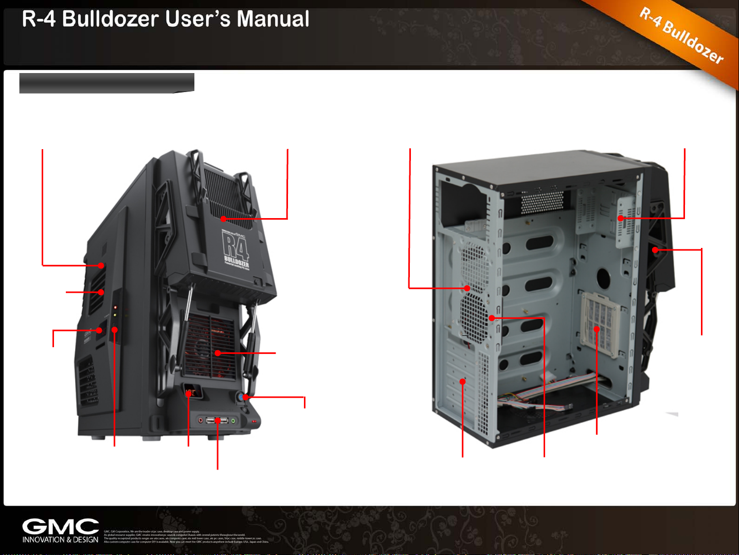
1.3 Case Overview
Side Panel
Side panel
80mm fan
Temperature
ODD Cover
92mm LED fan
Power switch
Rear 120mm fan
3.5” bay x 2
5.25” bay x 1
Fan Control button
Temperature
Front USB 2.0 / HD Audio port
Expansion slots x 7
Air filter
Key Lock
Page 5

Chapter 1. Product Introduction
1.3 Case Overview
R-4 ‘Bulldozer’ has two
integrated Thermometer sensors
and its LED displays are located
on the front and side panel. This
feature is extremely good for
users to monitor the PC
hardware temperature according
to the location of those sensors.
It also has integrated fan speed
controller so the users can
control the air flow and noise.
There are Temperature LED
displays and some I/O ports like
two audio jacks, 2 USB ports,
Power button and Reset button
at the bottom of the front panel.
On the right front panel, there is an eject
button to eject the ODD. The ODD tray panel
is supported by two spring steel bar: some
sort like shock absorber. There is a tuning
effect with 92mm LED and it is an intake fan
to provide the fresh air to cool down the
hardware inside the case.
Page 6

Chapter 2. Installation
2.1 Side Panel Removal 2.2 HDD Installation
① Remove the panel
thumbscrews from a side
panel and open it by swinging
it outwards.
② Inside the chassis,
there are HDD Bay,
120mm cooling fan at
the rear as well as
some wiring with
marked connectors.
(USB, PWR etc.)
① The HDD cage of R-4
‘Bulldozer’ is different with
normal case as well as it is
installed vertically. It is
located at the top-front of
Chassis. Unscrew the
circled part and pull out the
drive bay from the chassis.
② Fasten the drive in place
using the screws that case
includes. Two HDDs can
be mounted.
Page 7

Chapter 2. Installation
2.3 ODD Installation
③ Screw the circled part
and attach the HDD to the
drive bay.
① To install the ODD, you
just need to lift up the ODD
panel: it is tool-less. Hold
the low part of the ODD
cover and pull out.
(Note: Don’t need to
separate the whole front
panel from the Chassis)
② There 8 screws at both
sides to mount the ODD.
③ Connect the
appropriate power and
interface connectors from
the power supply and
motherboard to the device
(IDE, S-ATA).
④ Put the cover back to
the case.
Page 8

2.4 Power Supply, M/B,
Graphic Card Installation
Install the other components such as Power supply,
Mainboard, Graphic cards on the right place according
to the above picture.
2.5 Air Filter
2.6 Bottom Fan Hole
There is a washable
filter located behind the
92mm LED cooling fan
at the front panel.
(Note: We recommend
checking this filter at
least once a month
ly. Not washing it
initial
l result in higher
wil
system temperatures
and possible stability
problems.
For the bottom
panel, GMC has
prepared another
80mm ventilation
area for those who
needs it as more
airflow inside the
case.
Page 9

Chapter 2. Installation
2.7 Case LED & Switch Connections
① Connecting wires carry the
LEDs and switch connections
from the LEDs and switches
located behind the front bezel.
The switch and LEDs
connections are attached to the
LEDs and switches by wires to
header connectors that plugs
into pins on your mainboard.
② Take the connections from the
LEDs and switch header
connectors and locate the
corresponding pins on your
mainboard. Each mainboard is
ferent; consult your mainboard
dif
lation guide for the correct
instal
installation information. The
diagram shown at the left is for
example purposes only.
2.8 Connecting FPIO to Mainboard
▪ Connect USB Pin to Mainboard
These connectors are for USB
2.0 ports. Connect the USB
module cable to any of these
connectors.
Page 10

Chapter 2. Installation
2.8 Connecting FPIO to Mainboard
▪ Connect Audio Pin to Mainboard ▪ Connect Speaker Pin to Mainboard(4-pin Speaker)
This connector is for a
chassis-mounted front
panel audio I/O module that
supports either High
Definition Audio or AC’97
audio standard. Connect
one end of the front panel
audio I/O module cable to
this connector.
This connector is for the chassis-mounted system
warning speaker. The speaker allows you to hear system
beeps and warnings.
HD Audio
AC’ 97
Page 11

Chapter 2. Installation
2.9 Front thermometer power cable
connection
Place the thermometer
sensor inside of the chassis
lowing user’s preference
fol
Thermometer power
4pin connector
PSU 4pin connector
such as CPU, Graphic card
and HDD.
2.10 Side thermometer power cable
connection
Place the thermometer
sensor inside of the chassis
lowing user’s preference
Thermometer power
4pin connector
PSU 4pin connector
fol
such as CPU, Graphic card
and HDD.
Page 12

Chapter 2. Installation
2.11 Side fan cable connection
Fan 3pin connector
Fan controller connector
 Loading...