

Page 1

1
1300W
MAGNESIUM
184MM (7 1/4”)
MULTI FUNCTION
CIRCULAR SAW
MPS184M
INSTRUCTION MANUAL
Black
Cyan
Magenta
Yellow
Code: MPS184M
Date: 080508 Edition: 10 Op: DJ
Page 2

2
Contents
Warranty Power Tools
Whilst every effort is made to ensure your complete
satisfaction with this tool, occasionally, due to the mass
manufacturing techniques, a tool may not live up to our
required level of performance and you may need the
assistance of our service department.
The product is warranted for a 2-year repair warranty for
home domestic use from the date of original purchase.
If found to be defective in materials or workmanship, the
tool will be repaired free of charge.
A
small freight charge may apply. Proof of purchase is
essential. We reserve the right to reject any claim where
the purchase cannot be verified.
This warranty does not include damage or defects to the
tool caused by or resulting from abuse, accidents,
alterations or commercial or business use. It also does not
cover any bonus items or included accessories. Only the
power tool is covered under this warranty.
With continuing product development, changes may have
occurred which render the product received slightly
different to that shown in this instruction manual.
Please ensure that you store your receipt in a safe place.
Conditions apply to the above warranty. For full details of
the warranty terms and conditions please refer to our
website – www.gmcompany.com
For prompt service we suggest you log your service
request online - www.gmcservice.com.au, should you
not have access to the internet, please contact our
service department on 1300 880 001 (Australia)
or 0800 445 721 (New Zealand).
Warranty 2
Introduction 3
Environmental protection 3
Description of symbols 3
Specifications 3
General safety rules 4
Additional safety rules for circular saws 5
Accessories 7
Unpacking 7
Assembly 7
Know your product 8
Overview 9
Adjusting the cutting depth 9
Adjusting the bevel angle 9
Switching on and off 10
Making a cut 10
Overload cutout 11
Removing swarf and chips 11
Using a dust collection system 11
Using the parallel fence 11
Changing the blade 12
Maintenance 12
Cleaning 12
General inspection 13
Power cord maintenance 13
Troubleshooting 13
Page 3
3
Description of symbols
The rating plate on your tool may show symbols.
These represent important information about the
product or instructions on its use.
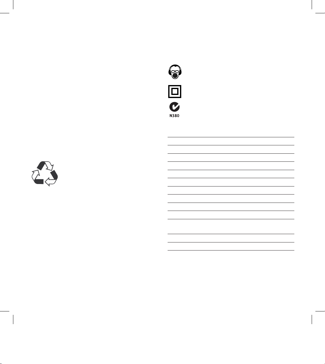
Wear hearing protection.
Wear eye protection.
Wear breathing protection.
Double insulated for additional protection.
Conforms to relevant standards
for electromagnetic compatibility.
Specifications
Voltage: 230 – 240V ~ 50 Hz
Power rating: 1300W
Max. duty cycle: 30 minutes
No load speed: 3500 min
-1
Blade diameter: 184mm (7 1/4”)
Blade teeth: 36 TCT
Blade arbour: 20mm
Blade kerf: 2.2mm
Bevel capacity: 0° to 45°
Cutting wood: Depth of cut at 90°: 52mm
Depth of cut at 45°: 30mm
Cutting metal (mild steel plate)
Optimum cutting thickness: 6mm
Electrical insulation: Double insulated
Weight: 6.2kg
This tool is double insulated. There are two independent
barriers of insulation to protect you from the possibility of
electric shock.
The sound intensity level for the operator may exceed
85dB(A) and sound protection measures are necessary.
Dear Customer
If you require any help with your product, whether it
is a Warranty claim, spare part or user information,
please phone our Help Line for an immediate response.
Phone 1300 880 001 in Australia or
0800 445 721 in New Zealand.
Introduction
Your new GMC power tool will more than satisfy
your expectations. It has been manufactured under
stringent GMC Quality Standards to meet superior
performance criteria.
You will find your new tool easy and safe to operate,
and, with proper care, it will give you many years
of dependable service.
CAUTION. Carefully read through this entire Instruction
Manual before using your new GMC Power Tool. Take
special care to heed the Cautions and Warnings.
Your GMC power tool has many features that will make
your job faster and easier. Safety, performance, and
dependability have been given top priority in the
development of this tool, making it easy to maintain
and operate.
Environmental protection
Recycle unwanted materials instead
of disposing of them as waste. All tools,
hoses and packaging should be sorted,
taken to the local recycling centre and
disposed of in an environmentally safe way
.
Page 4

4
General safety rules
WARNING. Read all instructions. Failure to follow all
instructions listed below may result in electric shock,
fire and/or serious injury. The term “power tool” in all of
the warnings listed below refers to your mains operated
(corded) power tool or battery operated (cordless)
power tool.
Save these instructions
1. Work area
a. Keep work area clean and well lit. Cluttered and dark
areas invite accidents.
b. Do not operate power tools in explosive atmospheres,
such as in the presence of flammable liquids, gases
or dust. Power tools create sparks which may ignite the
dust or fumes.
c. Keep children and bystanders away while operating
a power tool. Distractions can cause you to lose control.
2. Electrical safety
a. Power tool plugs must match the outlet. Never modify
the plug in any way. Do not use any adapter plugs with
earthed (grounded) power tools. Unmodified plugs and
matching outlets will reduce risk of electric shock.
b. Avoid body contact with earthed or grounded
surfaces such as pipes, radiators, ranges and
refrigerators. There is an increased risk of electric
shock if your body is earthed or grounded.
c. Do not expose power tools to rain or wet conditions.
Water entering a power tool will increase the risk of
electric shock.
d. Do not abuse the cord. Never use the cord for carrying,
pulling or unplugging the power tool. Keep cord away
from heat, oil, sharp edges or moving parts. Damaged
or entangled cords increase the risk of electric shock.
e. When operating a power tool outdoors, use an
extension cord suitable for outdoor use. Use of
a cord suitable for outdoor use reduces the risk of
electric shock.
3. Personal safety
a. Stay alert, watch what you are doing and use
common sense when operating a power tool.
Do not use a power tool while you are tired or under
the influence of drugs, alcohol or medication. A moment
of inattention while operating power tools may result in
serious personal injury.
b. Use safety equipment. Always wear eye protection.
Safety equipment such as dust mask, non-skid
safety shoes, hard hat, or hearing protection used for
appropriate conditions will reduce personal injuries.
c. Avoid accidental starting. Ensure the switch is in the
off position before plugging in. Carrying power tools with
your finger on the switch or plugging in power tools that
have the switch on invites accidents.
d. Remove any adjusting key or wrench before
turning the power tool on. A wrench or a key left
attached to a rotating part of the power tool may result
in personal injury.
e. Do not overreach. Keep proper footing and balance at
all times. This enables better control of the power tool in
unexpected situations.
f. Dress properly. Do not wear loose clothing or jewellery.
Keep your hair, clothing and gloves away from moving
parts. Loose clothes, jewellery or long hair can be caught
in moving parts.
g. If devices are provided for the connection of dust
extraction and collection facilities, ensure these are
connected and properly used. Use of these devices
can reduce dust related hazards.
Page 5

5
4. Power tool use and care
a. Do not force the power tool. Use the correct power tool
for your application. The correct power tool will do the job
better and safer at the rate for which it was designed.
b. Do not use the power tool if the switch does not turn
it on and off. Any power tool that cannot be controlled
with the switch is dangerous and must be repaired.
c. Disconnect the plug from the power source before
making any adjustments, changing accessories, or
storing power tools. Such preventive safety measures
reduce the risk of starting the power tool accidentally.
d. Store idle power tools out of the reach of children
and do not allow persons unfamiliar with the power
tool or these instructions to operate the power tool.
Power tools are dangerous in the hands of untrained users.
e. Maintain power tools. Check for misalignment or
binding of moving parts, breakage of parts and any
other condition that may affect the power tools operation.
If damaged, have the power tool repaired before use.
Many accidents are caused by poorly maintained
power tools.
f. Keep cutting tools sharp and clean. Properly
maintained cutting tools with sharp cutting edges are less
likely to bind and are easier to control.
g. Use the power tool, accessories and tool bits etc.,
in accordance with these instructions and in the
manner intended for the particular type of power
tool, taking into account the working conditions
and the work to be performed. Use of the power tool
for operations different from those intended could result
in a hazardous situation.
5. Service
a. Have your power tool serviced by a qualified repair
person using only identical replacement parts. This
will ensure that the safety of the power tool is maintained.
Additional safety rules for circular saws
WARNING! The warnings, precautions, and instructions
discussed in this manual cannot cover all possible
conditions and situations that may occur. The operator
must understand that common sense and caution are
factors which cannot be built into this product, but must
be supplied by the operator.
DANGER
a. Keep hands away from cutting area and the blade.
Keep your second hand on auxiliary handle, or motor
housing. If both hands are holding the saw, they cannot
be cut by the blade.
b. Do not reach underneath the workpiece. The guard
cannot protect you from the blade below the workpiece.
c. Adjust the cutting depth to the thickness of the
workpiece. Less than a full tooth of the blade teeth
should be visible below the workpiece.
d. Never hold piece being cut in your hands or across
your leg. Secure the workpiece to a stable platform. It is
important to support the work properly to minimize body
exposure, blade binding, or loss of control.
e. Hold power tool by insulated gripping surfaces when
performing an operation where the cutting tool may
contact hidden wiring or its own cord. Contact with
a “live” wire will also make exposed metal parts of the
power tool “live” and shock the operator.
f. When ripping always use a rip fence or straight edge
guide. This improves the accuracy of cut and reduces
the chance of blade binding.
g. Always use blades with correct size and shape
(diamond versus round) of arbour holes. Blades that
do not match the mounting hardware of the saw will run
eccentrically, causing loss of control.
h. Never use damaged or incorrect blade washers
or bolt. The blade washers and bolt were specially
designed for your saw, for optimum performance and
safety of operation.
Page 6

6
Causes and operator prevention of kickback:
• Kickback is a sudden reaction to a pinched, bound or
misaligned saw blade, causing an uncontrolled saw to
lift up and out of the workpiece toward the operator;
• When the blade is pinched or bound tightly by the kerf
closing down, the blade stalls and the motor reaction
drives the unit rapidly back toward the operator;
• If the blade becomes twisted or misaligned in the cut, the
teeth at the back edge of the blade can dig into the top
surface of the wood causing the blade to climb out of the
kerf and jump back toward the operator.
Kickback is the result of saw misuse and/or incorrect
operating procedures or conditions and can be avoided by
taking proper precautions as given below.
a. Maintain a firm grip with both hands on the saw and
position your arms to resist kickback forces. Position
your body to either side of the blade, but not in line
with the blade. Kickback could cause the saw to jump
backwards, but kickback forces can be controlled by the
operator, if proper precautions are taken.
b. When blade is binding, or when interrupting a cut
for any reason, release the trigger and hold the saw
motionless in the material until the blade comes to
a complete stop. Never attempt to remove the saw
from the work or pull the saw backward while the blade
is in motion or kickback may occur. Investigate and take
corrective actions to eliminate the cause of blade binding.
c. When restarting a saw in the workpiece, centre the
saw blade in the kerf and check that saw teeth are
not engaged into the material. If saw blade is binding,
it may walk up or kickback from the workpiece as the
saw is restarted.
d. Support large panels to minimise the risk of blade
pinching and kickback. Large panels tend to sag under
their own weight. Supports must be placed under the
panel on both sides, near the line of cut and near the
edge of the panel.
e. Do not use dull or damaged blades. Unsharpened
or improperly set blades produce narrow kerf causing
excessive friction, blade binding and kickback.
f. Blade depth and bevel adjusting locking levers
must be tight and secure before making cut.
If blade adjustment shifts while cutting, it may cause
binding and kickback.
g. Use extra caution when making a “plunge cut” into
existing walls or other blind areas. The protruding
blade may cut objects that can cause kickback.
The protruding blade may cut objects that can
cause kickback.
a. Check lower guard for proper closing before each
use. Do not operate the saw if lower guard does not
move freely and close instantly. Never clamp or tie the
lower guard into the open position. If saw is accidentally
dropped, lower guard may be bent. Raise the lower guard
with the retracting handle and make sure it moves freely
and does not touch the blade or any other part, in all
angles and depths of cut.
b. Check the operation of the lower guard spring. If the
guard and the spring are not operating properly, they
must be serviced before use. Lower guard may operate
sluggishly due to damaged parts, gummy deposits, or a
build-up of debris.
c. Lower guard should be retracted manually only for
special cuts such as “plunge cuts” and “compound
cuts.” Raise lower guard by retracting handle and as
soon as blade enters the material, the lower guard must
be released. For all other sawing, the lower guard should
operate automatically.
d. Always observe that the lower guard is covering
the blade before placing saw down on bench or
floor. An unprotected, coasting blade will cause the
saw to walk backwards, cutting whatever is in its path.
Be aware of the time it takes for the blade to stop after
switch is released.
e. Do not use abrasive wheels.
Page 7

7
Accessories
The GMC MPS184M Circular Saw is supplied with the
following accessories as standard:
1. 36T thin-kerf (2.2mm) TCT blade (fitted)
2. Blade wrench
3. Rip fence
4. Wood cutting dust extraction adaptor
5. Instruction manual
Unpacking
Due to modern mass production techniques, it is unlikely
that your GMC Power Tool is faulty or that a part is missing.
If you find anything wrong, do not operate the tool until the
parts have been replaced or the fault has been rectified.
Failure to do so could result in serious personal injury.
Assembly
The GMC circular saw is packed, fully assembled except
for the rip fence.
Page 8
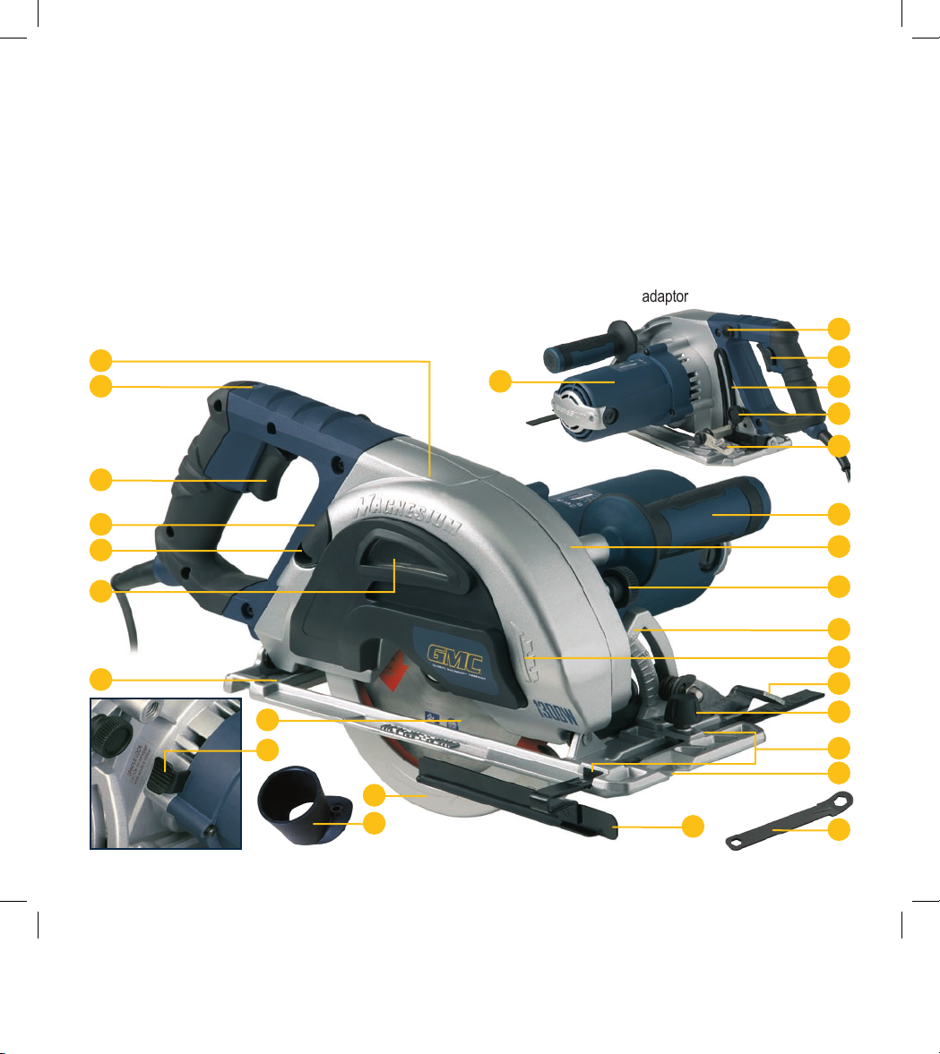
Know your product
1. Power on indicator
2. Trigger switch
3. Lock-off button
4. Motor housing
5. Handle
6. Bevel adjustment lever
7. Bevel scale
8. Parallel fence locking knob
9. Parallel fence
10. Cover release knob (front)
11. Cover release knob (rear)
12. Dust extraction plug
13. Removable cover section
14. Swarf/chip site glass
15. Lower blade guard
16. Base plate
17. Upper blade guard
18. Dust extraction port
19. Depth locking lever
20. Depth of cut indicator
21. Spindle lock lever
22. Blade
23. Blade wrench
24. Blade guide notch
25. Parallel fence slots
26. Blade rotation indicator
27. Overload protection reset switch
28. Wood cutting dust extraction
adaptor
8
3
2
1
4
5
6
26
8
9
11
10
18
13
14
15
17
12
19
20
16
22
24
25
7
27
23
28
21
Page 9
9
Overview
You have purchased a 1300W Magnesium Multi Function
Circular Saw that can cut both ferrous and non ferrous metals
quickly, cleanly and efficiently, as well as PVC pipe and soft
and hard timbers - all with the same blade. It can even saw
through wood containing nails!
The finished cut is burr free and there are virtually no sparks.
The saw utilises cold cutting technology and thus requires
no coolant. The metal can be handled as soon as it is cut,
saving time and adding to the safety of operation.
By loosening the bevel adjustment lever (6), the body and
the blade of the saw can be tilted to any angle up to 45° for
making angle cuts. Please note that the maximum depth of
cut is reduced when cutting at an angle.
A fixed upper blade guard (17) encloses the upper part of
the blade. As the saw advances through the work piece, the
pivoting lower blade guard (15) is pushed back by the edge of
the wood to expose only that part of the blade which is needed.
When the blade clears the work, the spring loaded lower
blade guard snaps back to completely enclose the blade.
Adjusting the cutting depth
CAUTION. Always ensure that the saw is switched off
and unplugged from the power supply before making any
adjustments.
1. Ensure that the saw is facing away from you.
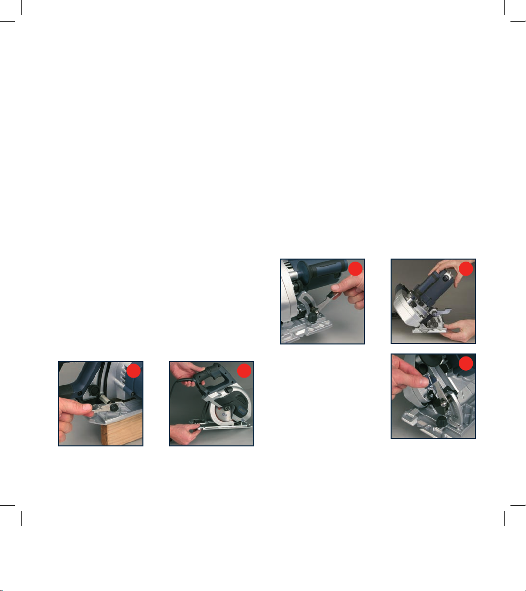
2. Loosen the depth locking lever (19) (Fig. A).
3. Hold the base plate flat against the edge of the work
piece and lift the body of the saw until the blade is at the
right depth (Fig. B). Use the depth of cut indicator (20) to
determine the cutting depth.
4. Tighten the depth locking lever (19).
Note. Always use the correct blade depth setting.
The correct blade depth setting for all cuts should not be
more than (6.35mm) 1/4” below the material being cut.
Allowing more depth will increase the chance of kickback
and result in a rough cut.
Note. The maximum depth of cut for mild steel plate is 6mm.
Adjusting the bevel angle
CAUTION. Always ensure that the saw is switched off
and unplugged from the power supply before making
any adjustments.
1. The saw can be adjusted to cut at any angle between
0° and 45°.
2. Loosen the bevel adjustment lever (6) located at the front
of the base plate (Fig. C).
3. Tilt the body of the
saw until the required angle
is reached (Fig. D) using the
bevel scale (7) as a guide.
4. Tighten the bevel adjustment
lever (6) to secure the base
plate (Fig. E).
Note. Always make a trial cut in
a scrap piece of material along a
guideline to determine how much you should offset
the blade from the guideline to make an accurate cut.
B
A
D
C
E
Page 10
10
Switching on and off
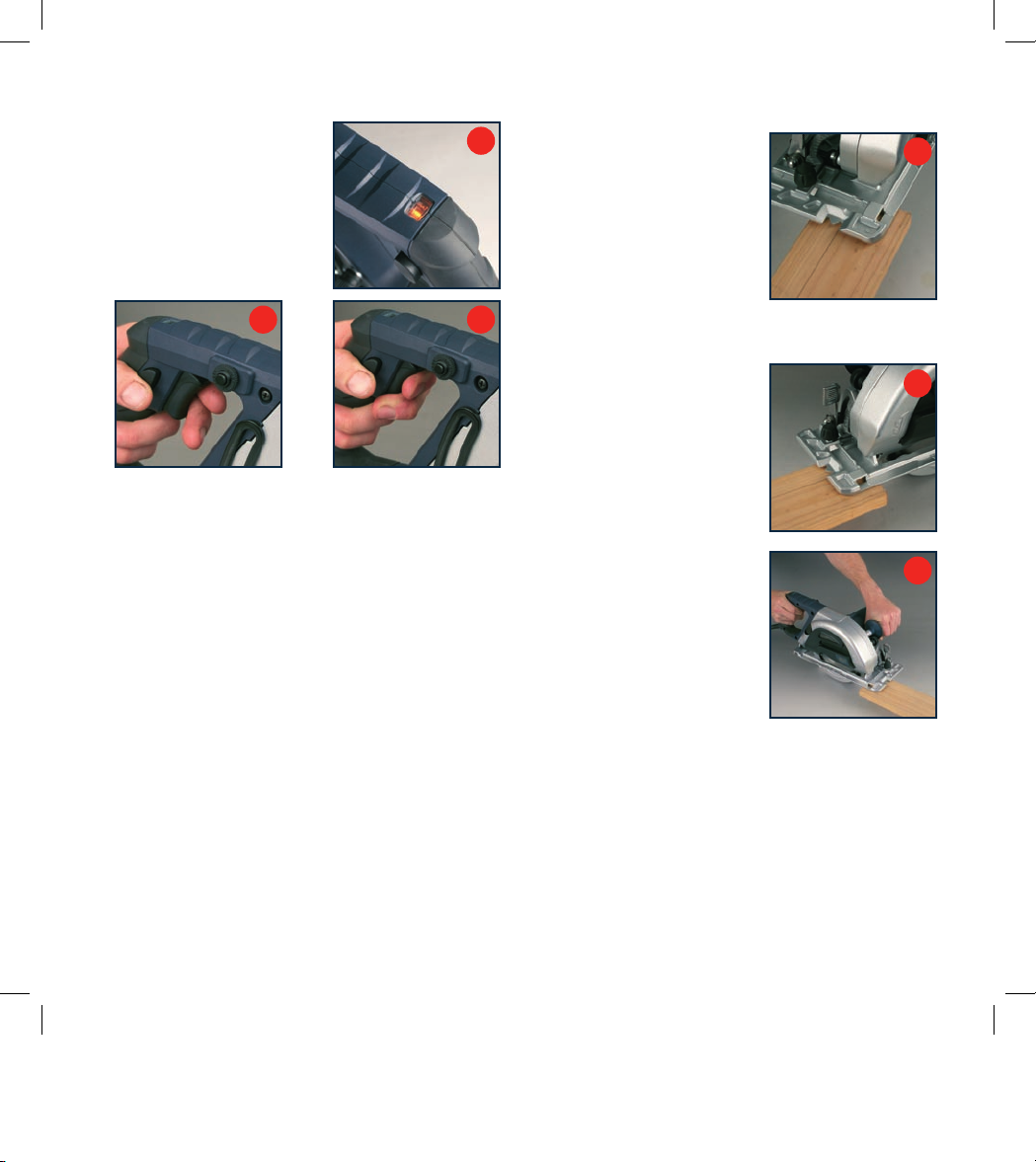
1. Connect the plug to the power
supply. The neon indicator
(1) indicates that power is
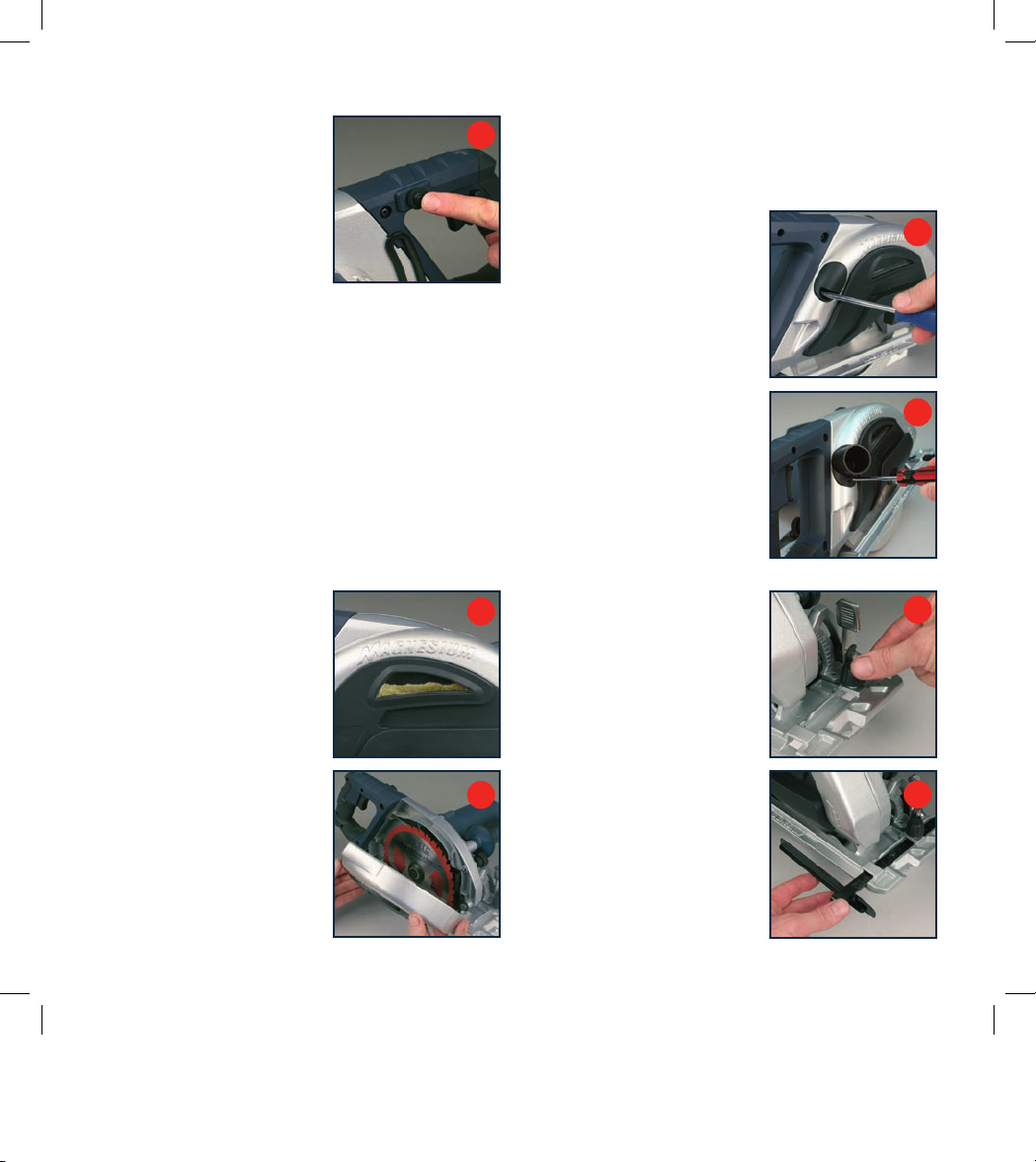
connected to the tool (Fig. F).
2. Depress the lock-off button
(3) (Fig. G) and squeeze the
trigger switch (2) (Fig. H).
3. The blade will take approximately 2 seconds to reach
full speed.
4. When you release the trigger, the machine turns off
and the lock-off button re-engages to prevent
accidental operation.
CAUTION. Allow the blade to come to a complete standstill
before setting the saw down.
Making a cut
1. Mark the line of cut on the
workpiece.
2. Adjust the depth of cut and
bevel angle as required.
3. When making 90° cross or rip
cuts, align your line of cut with
the outer blade guide notch on
the base of the saw (Fig. I).
4. When making 45° bevel cuts, align your line of cut with
the inner blade guide notch on the base of the saw.
5. Rest the front edge of the
base on the workpiece (Fig. J).
6. Start the motor by depressing
the lock-off button (3) and
squeezing the trigger switch (2).
Note. Always let the blade
reach full speed (approximately
2 seconds) before you begin to
cut into the work piece.
7. Slowly push the saw forward
using both hands (Fig. K).
8. When making a cut always
use steady, even pressure.
Forcing the saw causes rough
cuts and could shorten the life
of the saw or cause kickback.
Allow the blade and the saw to
do the work.
9. After completing your cut, release the trigger switch
and allow the blade to come to a complete stop.
Do not remove the saw from the work piece while
the blade is moving.
Note. Since blade thickness varies, always make a trial cut
in scrap material along the guideline to determine how much,
if any, the guideline must be offset to get an accurate cut.
H
G
J
K
I
Blade guide notch
F
Page 11
11
Overload cutout
The saw should not be overloaded
through attempts to take too deep
a cut, too fast a cut or operated
for too long. The saw should not
be operated for more than 30
minutes continuously after which
time it should be allowed to cool
for a period of at least 5 minutes.
If overloaded, the thermal overload circuit will trip. The button
of the reset switch (27) is partially ejected and the saw motor
cuts out. Restore power as follows.
1. Wait until the motor has cooled (approx. 5 minutes).
2. Depress the reset switch (27) (Fig. L).
3. Check that the saw is again operational and restart taking
care not to duplicate the circumstances that caused the
original overload.
Removing swarf and chips
1. The swarf and chips are collected within the removable
cover section of the handle. This provides a further
safety measure as it helps suppress sparks caused
by metal swarf.
2. Periodically check the level of
chips and swarf in the chamber
as seen through the site glass
(14) (Fig. M).
When the chamber is about 3/4
full, it must be emptied as follows.
3. Switch off the saw and unplug
it from the mains supply.
4. Unscrew the cover release
knobs (10 and 11) and take off
cover section (13) (Fig. N).
Note. Setting the saw to a
30 degree bevel makes it easier
to access the release knobs
(10 and 11).
5. Dispose of the swarf and chips and wipe the collection
chamber clean.
6. Replace the cover section (13) and the knobs (10 and 11).
Using a dust collection system
WARNING. A vacuum or other
type of dust collection system
must not be used when cutting
metal. It can cause an explosion!
1. For cutting wood only. Remove
the dust extraction plug (12)
(Fig. O).
2. Use the same fixing screw to
attach the wood cutting dust
extraction adaptor (28) to the
saw (Fig. P).
3. Connect the saw to a dust
extraction system.
4. When it is desired to change
the workpieces from wood
to metal, any dust extraction
system connected to the saw
MUST be disconnected and
the dust extraction plug (12)
replaced.
Using the parallel fence
The parallel fence (9) allows
you to make parallel cuts in a
workpiece, all at the same width.
CAUTION. Always ensure that
the saw is switched off and
unplugged from the power supply
before making any adjustments.
1. Loosen the parallel fence
locking knob (8) (Fig. Q).
2. Slide the parallel fence (9)
through the parallel fence
slots (25) in the base plate
(16) (Fig. R).
Q
M
N
O
R
L
P
Page 12
12
3. Adjust the parallel fence to the
required width and secure it in
position with the parallel fence
locking knob (8).
4. Ensure that the parallel fence
rests against the workpiece
along its entire length to give a
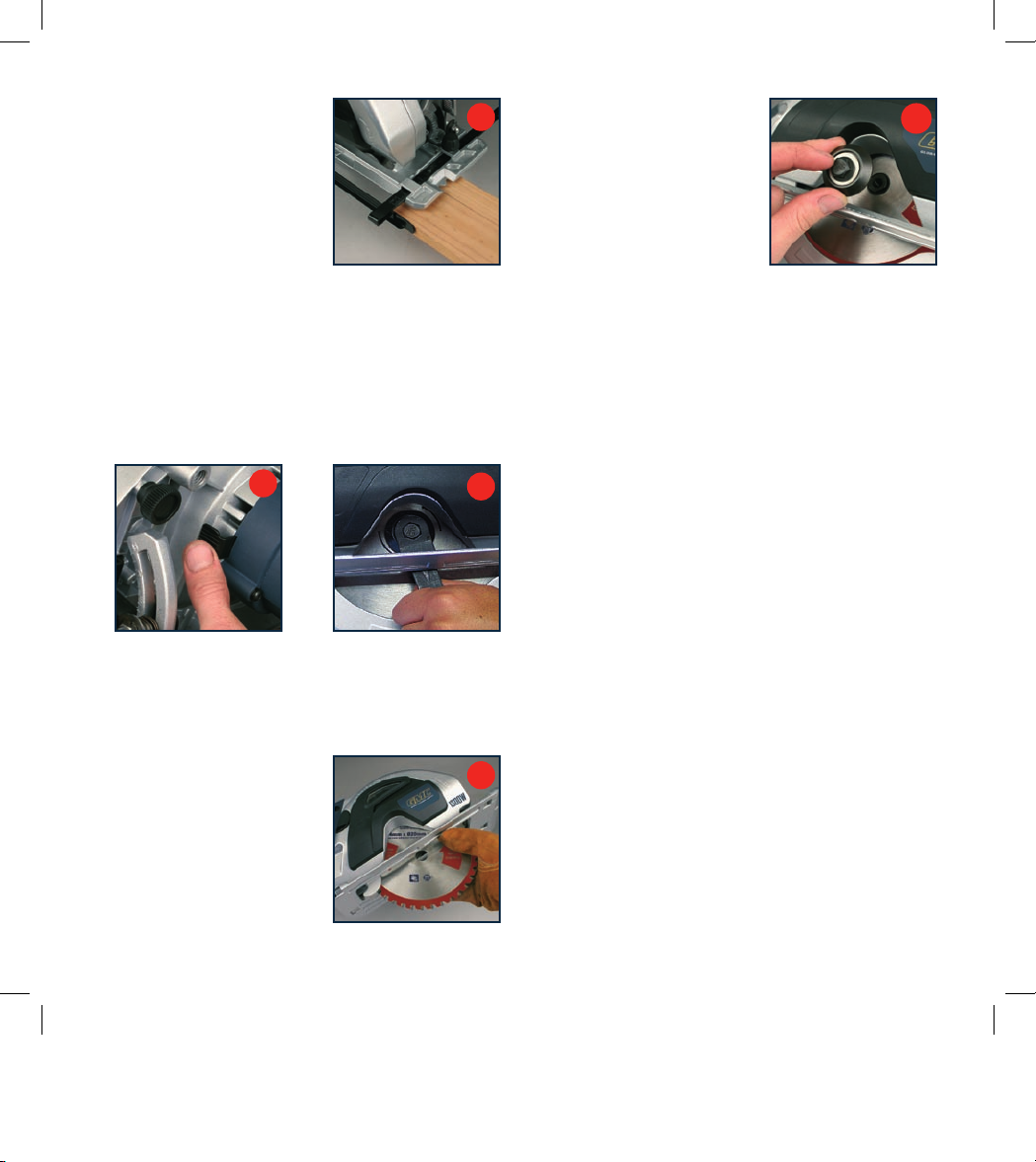
consistent parallel cut (Fig. S).
Changing the blade
CAUTION. Always ensure that the saw is switched off
and unplugged from the power supply before making any
adjustments.
1. Place saw on its side on a flat surface.
2. Rotate the saw blade by hand whilst depressing the
spindle lock lever (21) until the blade locks (Fig. T).
3. Whilst depressing the spindle lock lever, turn the blade
bolt anti-clockwise using the wrench provided (Fig. U).
4. Remove the outer blade flange and the blade bolt.
5. Raise the lower blade guard (15).
6. Remove the saw blade from
the inner flange and pull it
out (Fig. V).
7. Clean the saw blade flanges
thoroughly before mounting
the new saw blade. Wipe a
drop of oil onto the inner and
outer flange where they will
touch the blade.
8. Mount the new saw blade onto
the spindle and against the
inner flange.
9. Replace the outer flange and
tighten the blade bolt (Fig. W).
WARNING. The direction in
which the blade rotates has
to be the same as the direction
of the arrow marked on the
housing (26).
10. Ensure that the spindle lock lever (21) is released.
11. Before using the saw again, check that the safety
devices are in good working order.
IMPORTANT. After replacing the saw blade, make sure that
the saw blade runs freely by turning the blade by hand.
12. Plug the machine into a power socket and run the saw
under no load to check that it runs smoothly before
using it to cut any material.
Maintenance
WARNING. Always ensure that the tool is switched off and
the plug is removed from the power point before making any
adjustments or maintenance procedures.
Cleaning
1. Keep the tool’s air vents unclogged and clean at all times.
2. Remove dust and dirt regularly. Cleaning is best done
with a rag.
3. Re-lubricate all moving parts at regular intervals.
4. If the body of the saw needs cleaning, wipe it with a soft
damp cloth. A mild detergent can be used but nothing like
alcohol, petrol or other cleaning agent.
5. Never use caustic agents to clean plastic parts.
U
T
V
W
S
Page 13

13
CAUTION. Do not use cleaning agents to clean the
plastic parts of the tool. A mild detergent on a damp cloth
is recommended. Water must never come into contact
with the tool.
General inspection
Regularly check that all the fixing screws are tight. They
may vibrate loose over time.
Power cord maintenance
If the supply cord needs replacing, the task must be carried
out by the manufacturer, the manufacturer’s agent, or a
qualified electrical service repairer to avoid a safety hazard.
Troubleshooting
Trouble Problem Suggested remedy
Saw will not start Power cord not plugged in Ensure that the cord is connected to the power supply
Overload circuit tripped Wait 5 minutes for saw to cool, depress reset switch on
saw then restart
Power fault, fuse or circuit breaker tripped Check the power supply
Cord damaged Use authorised service centre to repair or replace
Burned out switch Use authorised service centre to repair or replace
Faulty motor Use authorised service centre to repair or replace the motor
Blade does not reach
full speed
Tool is overheating Turn off the tool and let it cool down to room temperature.
Inspect and clean the ventilation slots
Poor cutting Blunt blade Replace or sharpen circular saw blade
Vibration or abnormal
noise
Loose parts Check to see that all knobs and levers are securely
tightened including bevel adjustment knob, depth locking
lever and parallel fence locking knob
Blade vibrating Ensure that the blade nut is securely tightened
Moving parts excessively worn Use a qualified electrical service repairer to repair or replace
Page 14

14
Page 15

15
Page 16

GMC customer assist
If your product needs repairing or you simply need help
or advice, please contact us on our Customer Assist Line
1300 880 001 (Australia) or 0800 445 721 (New Zealand).
For prompt service we suggest you log your service request
online at www.gmcservice.com.au. Should you not have
access to the Internet, please contact our service department
on 1300 880 001 (Australia) or 0800 445 721 (New Zealand).
7am –7pm, 7days a week (AEST).
Please note that if repair is required, you must
provide a valid original purchase receipt.
You will need the following details at hand to log your service request;
Personal details: First & Last name, address, pick up address,
contact phone numbers, email address
Product details: Product number, date of purchase, retailer bought from,
State & postcode, receipt number, reason for the request,
c
opy of official purchase receipt
Attach your purchase receipt and save with this Manual for future reference
.
Please refer to our website www.gmcompany.com for full GMC warranty Terms and Conditions.
 Loading...