

Page 1

HYDRAULIC BOX & PAN BRAKES
MODEL: HBB-0412 / HBB-0410
HBB-0612 / HBB-0610
HBB-0812 / HBB-0810
HBB-1014 / HBB-1010
Operation & Parts Manual
Page 2

1
Table of Contents
1. Warning …………………………………………………………. 2-3
2. Machine construction & application …………………………. 4
3. Specifications …………………………………………………... 4
4. Transportation and Installation ……………………………….. 4-5
5. Safety inspection and safety rules …………………………… 5
6. Machine adjustment …………………………………………… 6-8
7. Lubrication ……………………………………………………… 9
8. How to use back gauge ……………………………………….. 10
9. Hydraulic & electrical diagrams ………………………………. 11-13
10. Operation instruction …………………………………………. 14-15
11. Troubleshooting & Parts manual with parts list ……………. 16-25
12. Warranty & return policy ……………………………………… 26
CAUTION
THIS IS VERY DANGEROUS MACHINE.
NEVER PLACE HANDS OR ANY PART OF BODY IN
THE MACHINE. BODILY INJURY COULD OCCUR. NEVER
OPERATE THE MACHINE WITHOUT PROPER EYES AND
BODY PROTECTION.
Page 3

2
Page 4

3
Page 5

4
I. Machine construction & Application
This machine is driven by hydraulic system, and all steel welded machine construction with high intensity,
good appearance, compact, safe and reliable performance.This machine is suitable for the sheet metal
processing plants, electrical protection, automobile manufacturing and other thin sheet metal bending
processing, etc.
Need to fill up the oil tank with Shell #68HD hydraulic oil or equivalent. Please make sure ¾ full of the tank.
Need to change hydraulic oil every 3 months or sooner subject to how many hours the machine in use every
day.
II. Specifications
III.Transportation and Installation
Crane or forklift is recommended
To move the machine, please move with forklift slowly and carefully, especially pay attention.
The machine is lifted by crane or moved by forklift after the removal of pallet.
Model
HBB-0412
HBB-0410
HBB-0612
HBB-0610
HBB-0812
HBB-0810
HBB-1014
HBB-1010
Max.bending thickness
HBB-0412:12Ga.
HBB-0410: 10Ga.
HBB-0612:12Ga
HBB-0610:10Ga
HBB-0812: 12Ga
HBB-0810: 10Ga
HBB-1014:14Ga
HBB-1010:10Ga
Max.bending width 48” (1220mm) 72” (1830mm) 96” (2440mm)
120”(3050mm)
Angle(°),degree 0 ~135 0 ~135 0 ~135 0 ~135
Hydraulic cylinder stroke
= clamp opening
3” 3” 3” 3”
Hydraulic cylinder pressure
(MP)
15 15 15 15
Hydraulic cylinder speed(mm/s) 50-58 50-85 50-85 50-75
Motor working pressure (Mp) 12 12 9-13 16
Motor Speed range(rpm) <30 <30 <30 <30
Motor power(HP) 5HP 5HP 7-1/2HP 10HP
N.W./G.W. LBS 4310 / 4630 5100/5300 6280 /6620 7510/37950
Packing size, inch 81x42x67 105x42x67 128x42x67 153x42x67
Page 6

5
2、Installation:When installing machine should be installed in a horizontal on the bottom of foundation,
level the machine very well, using leveling pads or foundation bolts.
IV. Safety inspection and Safety rules during and/or before operation
To ensure safety, it is necessary to do the following inspections for this machine after installation.
Check if the transportation procedure has influenced the accuracy and functions of the machine.
Check if the foundation of the machine is appropriate.
Check if the machine's main power switch should have earth wiring connected.
Use the multitester to check the stability of the three-phase voltage, and the low voltage must be the range of
208V-240V or high voltage must be 440V-480V, can not use voltage higher than 480V.
Check if the control panel function and push button are functioning
Check emergency stop function.
Check if safety protection accessories are functioning well
Check if other accessories, including hydraulic and pneumatic ones, are connected well (including transformer etc.)
Check if the oil amount indicator and air pressure indicator are normal.
Make sure no obstacle is around machine and control system.
Make sure no personnel are in dangerous area.
Tools and any unnecessary items are not allowed on the machine, moving parts, or similar locations.
Page 7

6
Before pressing/switching any button/switch always confirm that the button/switch is the correct one and never touch
a switch accidentally. Malfunction and potential danger might result.
Do not operate when wearing gloves or loose clothing. Malfunction and potential danger might result.
Do not touch switches with wet hands, an electric shock could occur.
If a work requires two or more operators, the cooperation among each operator must be well organized, every step of
each operator should be clarified to avoid potential danger.
Tools should be consisting with the machine's specifications, such as dimensions,weight and types.Grip workpieces
carefully to minimize movement and vibration between workpieces.Too much movement/vibration might result in
injuries of personnel, or damage the machine or workpiece.
Stop the machine before replacing workpiece, and reserve sufficient distance between workpiece and machine.Safety
for the electrical connection/disconnection
Electrical connection:
A cable with four wires is supplied to connect your machine into the 3 phase power supply.The exact power source
voltage, frequency, and number of phase shall be checked according to the installation diagram and circuit diagram.
The correct direction of main motor should be checked after connecting.
Electrical disconnection:
Be sure to disconnect this machine from power source, when you want to stop the job for maintenance or adjustment.
Grounding
The grounding of this model is carried out b y connecting the yellow/green terminal of supply cable to the grounding
terminal of power source. Be sure to ground your machine before connecting machine to power source in any
situation.
Warning!
Do not disconnect grounding terminal before disconnecting power source.
Description for the safety function of this machine
The following safety functions are equipped with this machine. Be sure to check and
ensure the correct function before you start to operate your machine:
The emergency stop device:
The machine is designed to be immediately stopped under emergency situation. As soon
as this device is actuated, any movement will be stopped in a short time after the actuation of emergency stop switch
(E-stop).
Be sure to check that machine action will stop immediately after this button is pressed and will not cause any action
when this button is disengaged.
V. Machine adjustment
CLEARANCE CHART
Before operation, please use the following formula to calculate & adjust the gap between the punch & die according to
the thickness of the work piece
For the following,A=material X2,for example,if you want to process 10Ga. thickness material,the
A=0.137X2=0.274inch
B=thickness of material -0.5~2mm. For example,if the thickness of the material is 2.0mm,the B=1.0mm. If the
thickness of the material is 10Ga, B=0.098” ( 12Ga.)
Page 8

7
How to adjust A and B, please pay attention to the following steps:
1) Adjust A: A can be adjusted through No.3 hand wheel left and right to adjust A.
2) Adjust B: Loose No 2 after adjust to the right pressure then tight No.1
Page 9

8
TABLE CROWNING COMPENSATION
If the angles of work-piece two sides are both on 90 degree,but middle side only 89 degree,Micro adjusting
screws at bending left and bottom beam for compensate the middle has the same angle.
1) Open the top beam,and then turn off the machine power
2) Tight screws A-G at upper beam and folding leaf,and make screw tight following different work-piece
crowing situation.
Page 10

9
VI. Lubrication
Please lubricate the following oil fittings ① ② ③ ④ four times a day, using lubrication oil # Shell
Tonna-33
Page 11

10
VII. How to use back gauge
This machine comes with a manual back gauge. Before first time use, please install the back gauge
first. Two support arms are mounted on the rear side of the table by screw 1 and 2, the stop bar # 6 on the
back gauge is mounted by screw 3.
Adjust the distance of back gauge: Loosen the butterfly nut # 4 and then T-nuts are released. Move the stop
bar # 6 back and forth to adjust the distance of the back gauge you need. Then tighten screw # 4.
Page 12

11
VIII、Hydraulic diagram
Page 13

12
Page 14

13
IX
Page 15

14
.
Operation Instruction
1)Turn the main power switch on the electric box to “ON” position
2) then power light is on , turn E-STOP RESET clockwise to fully release the E-stop push button, and
press bush button for pump start
Page 16

15
3)Angle set up: turn the black locking knob(circled in red ) to counter clockwise to release the set-up bar and
set up the bending degree you need then tighten the black locking knob, the bending angle degree can be
set-up from 0-135°。
This machine has two operation modes: one is for Auto cycle, and 2nd is for inch ( jog).
4)-1 on inch ( jog ) mode:
Press unclamp foot pedal, the top beam raises up, please insert the material in ,then press clamp pedal to
close down the top beam with fingers. ( caution: the top beam must be closed down tightly, otherwise,
The bending leaf will be not lifted up to make bend. ) press BEND foot pedal to jog the bending leaf up.
Or push the following circled black controller up to BEND position, the bending leaf will go up joggly and
push the black controller down to release position, the bending leaf will go down joggly.
Page 17

16
4)-2 on Auto cycle operation mode:
Press BEND foot pedal, the bending leaf automatically go up and make bend and then automatically go
back to the bottom postion and stops to make one autocycle bending. Or 2nd way, push and release the
above circled black controller up to BEND position, the bending does the same automatic cycle bending and
then stops.
Page 18

17
X.Troubleshooting
Troubles Possible cause Remedy
Hydraulic cylinder crawling
Hydraulic or pipe has air Start the hydraulic system and forth several times to
the maximum stroke, forced exclusion of air; seal the
pipeline and system.
Somewhere a negative
pressure in the hydraulic
cylinder
Locate a negative pressure at the hydraulic cylinder
and sealed, then exhaust the air.
Ring seal too tight Adjustment ring, so as not to loose not tight, to ensure
that the rod can be pulled back and forth by hand.
Cylinder wall or piston
surface strain, badly worn or
local corrosion
Boring the cylinder bore, the piston reassortment
Leakage of the hydraulic
cylinder
Cylinder bore and piston with
the gap due to wear resulting
in increased tolerance, rod
surface damage
Repair rod damage
Seal the edges injury or aging
Replace the seals
Pipe joint is not seal tightly
Replace the seals
Hydraulic cover is not seal
tightly
Check the seal contact surface machining accuracy
and aging, be replaced or repaired.
Due to poor exhaust air
temperature adiabatic
compression cause local
damage seals
Inspect the exhaust system, or additional exhaust,
timely exhaust.
Sound and noise
1) hydraulic cylinder has air
2) Cylinder rod lack oil
1)Slow movement of the piston several times, each
time went to the top, to exclude gas tank, you can
eliminate this serious noise, but also to prevent seals
burns.
2) cylinder rod oil can also cause less noise, this time
should be oiled at the pole.
Page 19

18
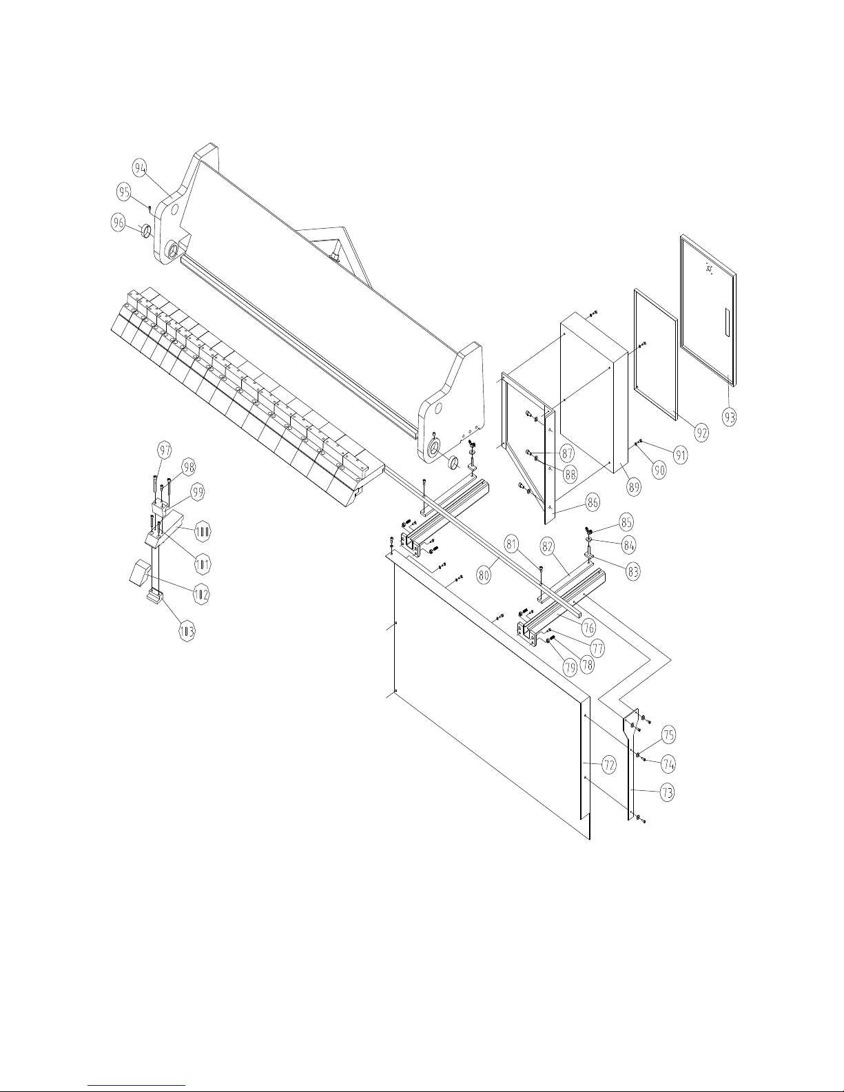
XI. Parts breakdown manual and parts list
Page 20

19
Page 21
20
Page 22

21
Page 23

22
No. Desc. Q’ty Note
1 Body 1
2 Hydraulic Cylinder 2
2pcs
different
3 Connecting plate on hydraulic cylinder 2
4 Six pyramid end screw set M8X12 4
5 Fixed upper pole on hydraulic cylinder 2
6 cotter 4X40 2
7 Fixed bottom pole on hydraulic cylinder 2
8 eccentric disk shaft 2
9 bush 12050 2 SF-1
10
oil cup
8 4
11
Eccentric disc holder
2
12 Eccentric disk 2
13 Eccentric disk fixed plate 2
14 Spring washer 12 2
15
hexagon socket cap screws
M12X35 2
16 Leaf beam right rotation shaft 1
17 Angle plate 1
18 Angle plate 1
19
hexagon socket cap screws
M8X40 1
20 handle M10X30 1
21 Round pin 10X60 1
22 Angle rotation boards 1
23
hexagon socket cap screws
M6X16 2
Page 24

23
24 Emergency stop stand 1
25 Bolt seat 2
26 Head frame shaft 2
27 Hex nut 4
28 Hex screw 4
29 Hexagon socket countersunk head screws M10X25 4
30 cover 2
31 cover 2
32 U-block 2
33 Spacer 4
34 Side plate of U-block 4
35 Bush 5520 4 SF-1
36 Hex cylinder head screw M12X25 24
37 Right motor seat 1
38 Spring washer 12 8
39 Hex cylinder head screw M12X40 8
40 Bush 4520 2 SF-1
41 Hexagon socket countersunk head screws M8X12 4
42 key 12X45 2
43 Large chain wheel 2
44 Screw M10 8
45 Inner hexagon socket set screw M10X20 8
46 Driven sleeve 2
47 Hex bolt M10X65 4
48
Driven shaft
1
49
Small chain wheel
2
50 Key 14X70 2
51 Handle wheel Φ16X125 2
52 Spring washer 12 4
53 Hex cylinder head screw M12X40 4
54 Spring pin 6X32 2
55
Lead screw
2
56 motor 2
57 Hex cylinder head screw M10X40 4
58
Plate
2
59
Nut
2
60 Inner hexagon socket set screw M10X40 4
61 Oil cup M8X1 2
62
shaft
2
Page 25

24
63
Emergency seat
2
64 Flat washer 6 4
65 Hex cylinder head screw M6X16 4
66 Flat washer 12 2
67 Adjustable handle M12X25 2
68
Touch off cover
1
69 Inner hexagon socket set screw M10X12 1
70 Nut M10 1
71 Hex.socker M10X50 1
72
Back liner insert
1
73
tailgate stents
1
74 hexagon socket cap screws M6X16 8
75 flat gasket 6 8
76
Keep-off stents
2
77 hexagon socket cap screws M12X25 4
78 Allen flat end set screws M10X25 4
79 nut M10 4
80
Keep-off square bar
1
81 hexagon socket cap screws M8X16 2
82
striker plate
2
83
Keep-off square bar fixing parts
2
84 big washer 10 2
85 butterfly nut M10 2
86
Electric box connection frame
1
87 hexagon socket cap screws M10X20 3
88 flat washer 10 3
89
Electrical box
1
90 flat washer 6 4
91 hexagon socket cap screws M6X16 4
92
Electric plate
1
93
Electric box door
1
94
Top rack
1
95 Oil cup M8X1 2
96 bush 5020 4 SF-1
97 hexagon socket cap screws M10X65 34
98 hexagon socket cap screws M12X25 17
99
Upper blade pressure block
1set
100
Lower blade
1set
101 hexagon socket cap screws M12X50 34
Page 26

25
102
Upper blade
1set
103
Lower blade pressure block
1set
104 Oil cup M8X1 2
105
Copper dash
4
106
Nylon pressure block
2
107
Left motor seat
1
108
folding fan left shaft
1
109 bush 3820 4
110 bush 5020 2 SF-1
111
Bending plate banners
1
112 hexagon socket cap screws M12X40 10
113
Bending boy reinforcing plate
1
114 Hex bolt thread M10X25 8
115 standard spring washer 10 8
116
Back bending plate
1
117
Left connecting
1
118 bush 3820 4 SF-1
119 nut M10 1
120 Hex bolt thread M10X50 1
121
Bending body
1
122 Hex bolt thread M12X40 3
123
knife edge angle iron
1
124 Hex bolt thread M12X30 7
125 Flat washer 12 7
125a standard spring washer 12 7
126 flat end set screws M12X40 6
127 hexagon socket cap screws M8X40 1
128 Inner hexagon socket set screw M12X35 2
129 standard spring washer 16 10
130 Hex bolt thread M16X65 10
131 nut M20 2
132 Hex bolt thread M20X75 2
133
Right connecting
1
134
Press block
1
135 Hex bolt thread M12X40 7
135a standard spring washer 12 7
136
Front guard
1
137 Flat washer 6 11
138 hexagon socket cap screws M6X16 11
Page 27

26
139
plate
1
140 cross recess pan head screw M4X8 4
141 hexagon socket cap screws M8X16 4
142
carrying handle
2
143
Operations support
1
144 foot pedal 3
145 oil cylinder 1
146 hexagon socket cap screws M6X16 4
147 Flat washer 6 4
148 Oil temperature measure 1
149 oil absorption filter oil meter 1
150 motor 1
151 Hydraulic cylinder 1
152 Motor tube 2
进 2.4 出
1.6
153 Hydraulic cylinder tube 2
进 2.6 出
1.8
154 Drain mouth matching oil plug 1
155 double row roller chain 10A 2 各 40 节
Page 28

27
Page 29

28
Note: This manual is only for your reference. Any specification changes and
improvement are subject to change without prior to notice. And please the power source
voltage in your shop before wiring up this machine. Please be carefully and BE SAFE.
 Loading...