

Page 1
Page 2

Chevrolet/GMC Duramax Diesel Supplement (GMNA-Localizing-U.S./Canada-
11354421) - 2018 - CRC - 10/10/17
Contents
Introduction . . . . . . . . . . . . . . . . . . . . . . 2
In Brief . . . . . . . . . . . . . . . . . . . . . . . . . . . 5
Instruments and Controls . . . . . . . . 9
Driving and Operating . . . . . . . . . . 24
Vehicle Care . . . . . . . . . . . . . . . . . . . . 84
Service and Maintenance . . . . . 120
Technical Data . . . . . . . . . . . . . . . . 130
Index . . . . . . . . . . . . . . . . . . . . 134
Page 3

Chevrolet/GMC Duramax Diesel Supplement (GMNA-Localizing-U.S./Canada-
11354421) - 2018 - CRC - 3/23/18
2 Introduction
Introduction
The names, logos, emblems,
slogans, vehicle model names, and
vehicle body designs appearing in
this manual including, but not limited
to, GM, the GM logo, CHEVROLET,
GMC, the CHEVROLET and GMC
Truck Emblems, SILVERADO,
SIERRA, DENALI, EXPRESS,
SAVANA, COLORADO, CANYON,
and Duramax are trademarks and/or
service marks of General Motors
LLC, its subsidiaries, affiliates,
or licensors.
For vehicles first sold in Canada,
substitute the name “General
Motors of Canada Company” for
GMC and Chevrolet Motor Division
wherever it appears in this manual.
This manual describes features that
may or may not be on the vehicle
because of optional equipment that
was not purchased on the vehicle,
model variants, country
specifications, features/applications
that may not be available in your
region, or changes subsequent to
the printing of this owner’s manual.
Refer to the purchase
documentation relating to your
specific vehicle to confirm the
features.
This manual contains information
that pertains to the operation of your
diesel engine. It also contains your
Diesel Maintenance Schedule. The
sections in this manual correspond
to the sections in your owner’s
manual. This manual, along with
your owner’s manual, will assist you
in the proper use and maintenance
of your vehicle.
Keep this manual in the vehicle for
quick reference.
Canadian Vehicle Owners
A French language manual can be
obtained from your dealer, at
www.helminc.com, or from:
Propriétaires Canadiens
On peut obtenir un exemplaire de
ce guide en français auprès du
concessionnaire ou à l'adresse
suivante:
Helm, Incorporated
Attention: Customer Service
47911 Halyard Drive
Plymouth, MI 48170
USA
Litho in U.S.A.
Part No. 23380346 C Third Printing
©
2018 General Motors LLC. All Rights Reserved.
Page 4

Chevrolet/GMC Duramax Diesel Supplement (GMNA-Localizing-U.S./Canada-
11354421) - 2018 - CRC - 10/10/17
Using this Supplement
This supplement contains
information specific to the unique
components of the vehicle. It does
not explain everything you need to
know about the vehicle. Read this
supplement along with the owner’s
manual to learn about the vehicle's
features and controls.
Index
A good place to look for what you
need is the Index in the back of this
supplement. It is an alphabetical list
of what is in the supplement, and
the page number where you will
find it.
Introduction 3
Page 5

Chevrolet/GMC Duramax Diesel Supplement (GMNA-Localizing-U.S./Canada-
11354421) - 2018 - CRC - 10/10/17
4 Introduction
2 NOTES
Page 6

Chevrolet/GMC Duramax Diesel Supplement (GMNA-Localizing-U.S./Canada-
11354421) - 2018 - CRC - 10/10/17
In Brief
Initial Drive Information
Transmission . . . . . . . . . . . . . . . . . . . . 5
Performance and Maintenance
Engine Oil Life System . . . . . . . . . . 6
Diesel Particulate Filter . . . . . . . . . . 6
Diesel Exhaust Fluid . . . . . . . . . . . . 7
Initial Drive
Information
Transmission
Cold Operation (8-Cylinder Pickup
Models Only)
When temperatures are very cold,
the transmission will prevent certain
operations to protect against
damage. The information below
shows shift range availability based
on transmission oil temperature:
.
All shift ranges available at
−25 °C (−13 °F) or above.
.
2 (Second) and 3 (Third) shift
ranges only at −35 °C (−31 °F) to
−25 °C (−13 °F).
.
2 (Second) shift range only at
−35 °C (−31 °F) or lower.
Torque converter clutch operation
will also be prevented when air or
transmission oil temperatures are
below certain levels.
In Brief 5
For areas where ambient
temperatures are below −40 °C
(−40 °F), use synthetic transmission
fluid approved to Allison
Transmission specification TES-295.
See Recommended Fluids and
Lubricants 0 126 and Automatic
Transmission Fluid 0 95.
Adaptive Shift Controls
(8-Cylinder Pickup Models Only)
The shift quality of a new vehicle
may not be ideal because the
Adaptive Shift Control process may
not have determined the best
settings for a particular shift or
condition. Shift quality will improve
with continued driving.
Low Traction Mode (All Models)
Low Traction Mode aids in vehicle
acceleration on slippery road
surfaces such as ice or snow. By
selecting 2 (Second) using Range
Selection Mode while at a stop, the
transmission will limit torque to the
drive wheels to prevent slippage.
Page 7

Chevrolet/GMC Duramax Diesel Supplement (GMNA-Localizing-U.S./Canada-
11354421) - 2018 - CRC - 10/10/17
6 In Brief
Heater Performance Mode
(8-Cylinder Pickup Models Only)
When cold weather conditions are
detected, the transmission raises
part throttle upshift points after the
1 (First) to 2 (Second) upshift to
increase engine speed. This feature
shortens engine and cab warm up
times.
When the transmission is in this
mode, upshifts may be delayed.
This is normal and does not indicate
an operational problem.
Four-Wheel Drive (8-Cylinder
Pickup Models Only)
When operating in 4
(Four-Wheel-Drive Low), there is a
very deep gear reduction. The
resulting shifts will feel exaggerated.
n
Performance and Maintenance
Engine Oil Life System
The engine oil life system calculates
engine oil life based on vehicle use
and displays the CHANGE ENGINE
OIL SOON message when it is time
to change the engine oil and filter.
The oil life system should be reset
to 100% only following an oil
change. See “Engine Oil Life
System” in the owner’s manual.
Diesel Particulate Filter
The Duramax engine is equipped
with a Diesel Particulate Filter (DPF)
that will filter or trap particulates.
The DPF is under the vehicle in the
exhaust system.
Depending on a number of factors
monitored by the engine computer,
the DPF will need to be cleaned of
accumulated solids. When a
cleaning is needed, the engine
computer will initiate a cleaning
action by warming the exhaust gas
temperature. This feature has been
designed to operate automatically,
with limited operator involvement or
awareness.
Noise may be heard at low speeds
when the emission controls are
active. This is normal.
Cleaning the DPF (Exhaust
Filter)
While the DPF cleaning is
automatically controlled by the
engine computer, the Driver
Information Center (DIC) may
display a message. The vehicle will
need to operate continuously until
the message is no longer displayed.
Cleaning occurs most effectively
above 50 km/h (30 mph). If the
vehicle is returned to idle during the
cleaning process, the driver may
notice a slightly different sound or a
slightly elevated engine idle speed.
This is normal. No action is required
on the part of the driver during a
regular DPF cleaning. See Diesel
Particulate Filter 0 34.
Page 8

Chevrolet/GMC Duramax Diesel Supplement (GMNA-Localizing-U.S./Canada-
11354421) - 2018 - CRC - 10/10/17
Special DPF Driver Messages
If the vehicle is used for numerous
short trips or extended slow-speed
operation, the engine computer may
not be able to adequately heat up
the exhaust system to clean the
DPF effectively. The engine
computer has been designed to
continuously monitor the condition
of the DPF. When the engine
computer detects that the DPF is
nearly full of particulates and that
the vehicle is not being operated in
a manner that would allow effective
automatic DPF cleaning, the Driver
Information Center (DIC) will display
a message.
If the vehicle continues to be driven
in a manner that prevents effective
DPF cleaning, the DPF will become
plugged with particulates. If this
occurs, the engine computer will
turn on the Malfunction Indicator
Lamp (Check Engine Light) in the
instrument cluster, and the DIC will
display the message ENGINE
POWER IS REDUCED. See Diesel
Particulate Filter 0 34.
Fuel
Use Ultra Low Sulfur Diesel
Fuel (ULSD)
Use ULSD only. The emission
control hardware used on the
vehicle may be damaged by using
fuel with high sulfur levels. Use only
fuel that is dispensed from pumps
bearing the ULSD label.
Do Not Use Low Sulfur Diesel
Fuel (LSD)
Do not use fuel that is dispensed
from pumps bearing the LSD label.
Do Not Use Non-Highway Fuel
Fuel labeled as off road or
non-highway is typically very high in
sulfur content and will damage the
emission control system.
Non-highway fuel is not intended for
use in on-highway vehicles and
does not have the fuel properties
needed by the DPF-equipped
Duramax diesel.
In Brief 7
In addition:
.
Use the correct engine oil.
.
Do not add gasoline to
diesel fuel.
.
Do not modify the induction or
exhaust systems.
See Fuel for Diesel Engines 0 45
and Engine Oil 0 91.
Diesel Exhaust Fluid
Diesel Exhaust Fluid (DEF) is used
with diesel engines to reduce the
amount of regulated emissions
produced. The DEF system must be
maintained for the vehicle to run
properly.
DEF is not a fuel additive. For
refilling instructions, see Diesel
Exhaust Fluid 0 37. DEF should not
be mixed with or added to diesel
fuel. DEF freezes when exposed to
temperatures below −11 °C (12 ° F).
Page 9

Chevrolet/GMC Duramax Diesel Supplement (GMNA-Localizing-U.S./Canada-
11354421) - 2018 - CRC - 10/10/17
8 In Brief
Locating Diesel Exhaust Fluid
DEF can be purchased at a
Chevrolet or GMC dealer. It can
also be purchased at authorized
vehicle and truck dealerships.
Additionally, some diesel truck
fueling stations or retailers may
have DEF for purchase. For
vehicles with an active OnStar
subscription, OnStar can help to
locate a DEF retailer. See
“Customer Assistance Offices” in
the owner manual for phone
numbers to assist you in contacting
a GM dealer. See Recommended
Fluids and Lubricants 0 126.
As the DEF tank becomes low on
fluid, warnings begin with
approximately 1 600 km (1,000 mi)
of remaining range. These warnings
will increase as the tank becomes
empty. Once the tank is empty, the
vehicle speed will be limited. If there
is an issue with the quality of the
fluid or the exhaust fluid system,
warnings will be displayed in the
Driver Information Center (DIC).
See Diesel Exhaust Fluid 0 37.
®
Page 10

Chevrolet/GMC Duramax Diesel Supplement (GMNA-Localizing-U.S./Canada-
11354421) - 2018 - CRC - 10/10/17
Instruments and Controls
Warning Lights, Gauges, and
Indicators
Instrument Cluster . . . . . . . . . . . . . 10
Fuel Gauge . . . . . . . . . . . . . . . . . . . . 16
Engine Oil Pressure Gauge . . . . 17
Malfunction Indicator Lamp
(Check Engine Light) . . . . . . . . . 18
Wait-to-Start Light . . . . . . . . . . . . . 20
Diesel Exhaust Fluid (DEF)
Warning Light . . . . . . . . . . . . . . . . 20
Power Take-Off Light (Chassis
Cab Only) . . . . . . . . . . . . . . . . . . . . 21
Information Displays
Driver Information
Center (DIC) . . . . . . . . . . . . . . . . . 21
Vehicle Personalization
Vehicle Personalization (Pickup
Models) . . . . . . . . . . . . . . . . . . . . . . 22
Vehicle Personalization (Van
Models) . . . . . . . . . . . . . . . . . . . . . . 23
Instruments and Controls 9
Page 11
Chevrolet/GMC Duramax Diesel Supplement (GMNA-Localizing-U.S./Canada-
11354421) - 2018 - CRC - 10/10/17
10 Instruments and Controls
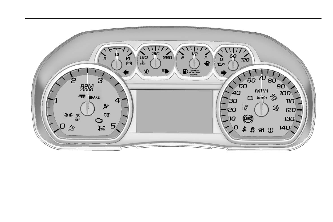
Warning Lights, Gauges, and Indicators
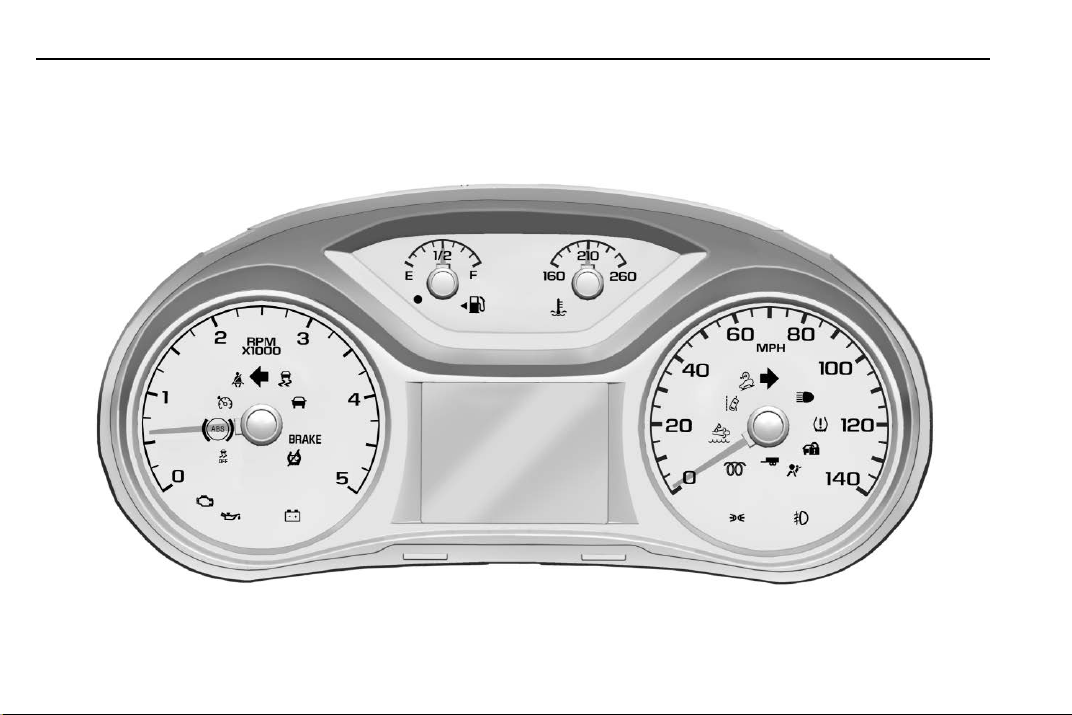
Instrument Cluster
English Base Level 4-Cylinder Pickup Shown, Metric Similar
Page 12
Chevrolet/GMC Duramax Diesel Supplement (GMNA-Localizing-U.S./Canada-
11354421) - 2018 - CRC - 10/10/17
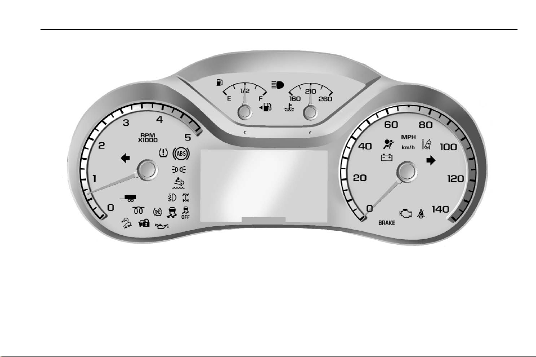
Instruments and Controls 11
English Uplevel 4-Cylinder Pickup Shown, Metric Similar
Page 13
Chevrolet/GMC Duramax Diesel Supplement (GMNA-Localizing-U.S./Canada-
11354421) - 2018 - CRC - 10/10/17
12 Instruments and Controls
English Base Level 8-Cylinder Pickup Shown, Metric Similar
Page 14
Chevrolet/GMC Duramax Diesel Supplement (GMNA-Localizing-U.S./Canada-
11354421) - 2018 - CRC - 10/10/17
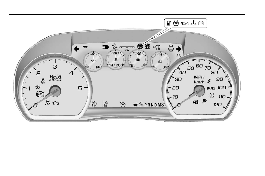
Instruments and Controls 13
English Uplevel 8-Cylinder Pickup Shown, Metric Similar
Page 15
Chevrolet/GMC Duramax Diesel Supplement (GMNA-Localizing-U.S./Canada-
11354421) - 2018 - CRC - 10/10/17
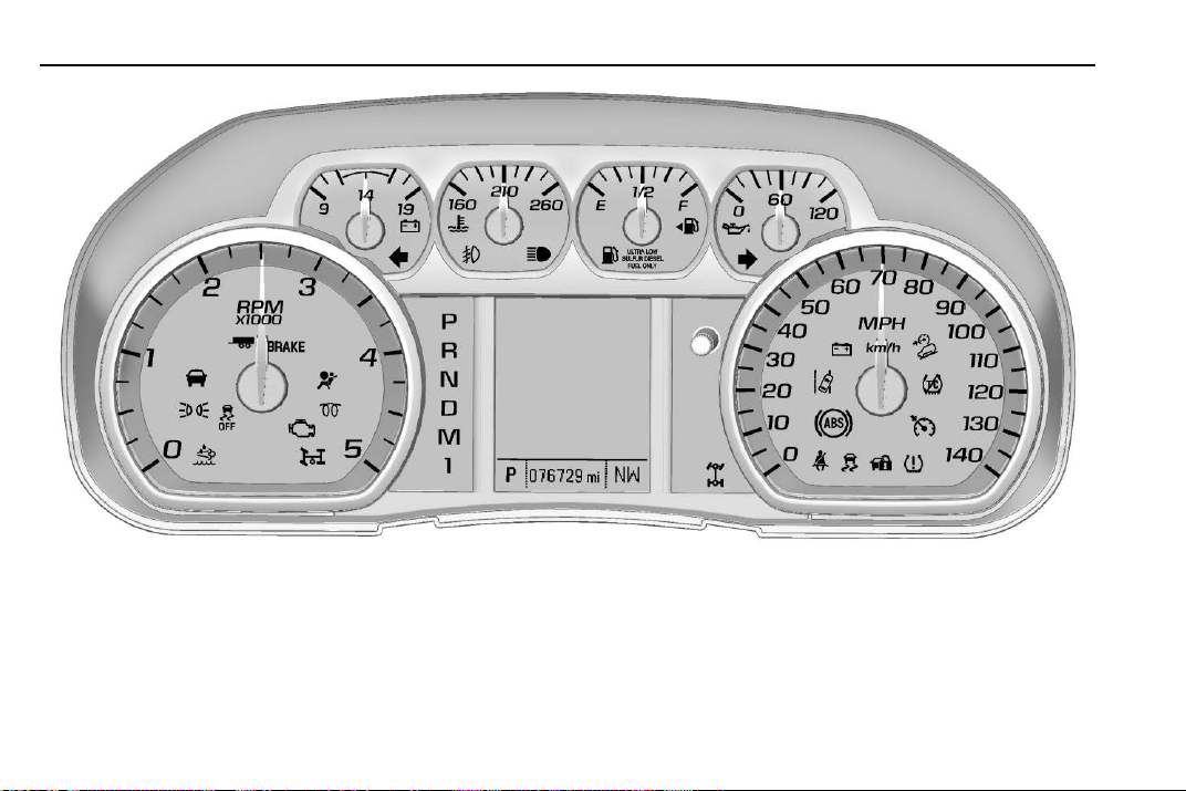
14 Instruments and Controls
English 8-Cylinder Denali Pickup Shown, Metric Similar
Page 16
Chevrolet/GMC Duramax Diesel Supplement (GMNA-Localizing-U.S./Canada-
11354421) - 2018 - CRC - 10/10/17
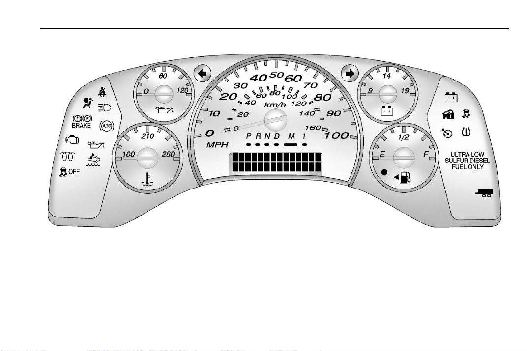
English Van Shown, Metric Similar
Instruments and Controls 15
Page 17
Chevrolet/GMC Duramax Diesel Supplement (GMNA-Localizing-U.S./Canada-
11354421) - 2018 - CRC - 10/10/17
16 Instruments and Controls
See the owner ’s manual for warning
lights and gauges not listed in this
supplement.
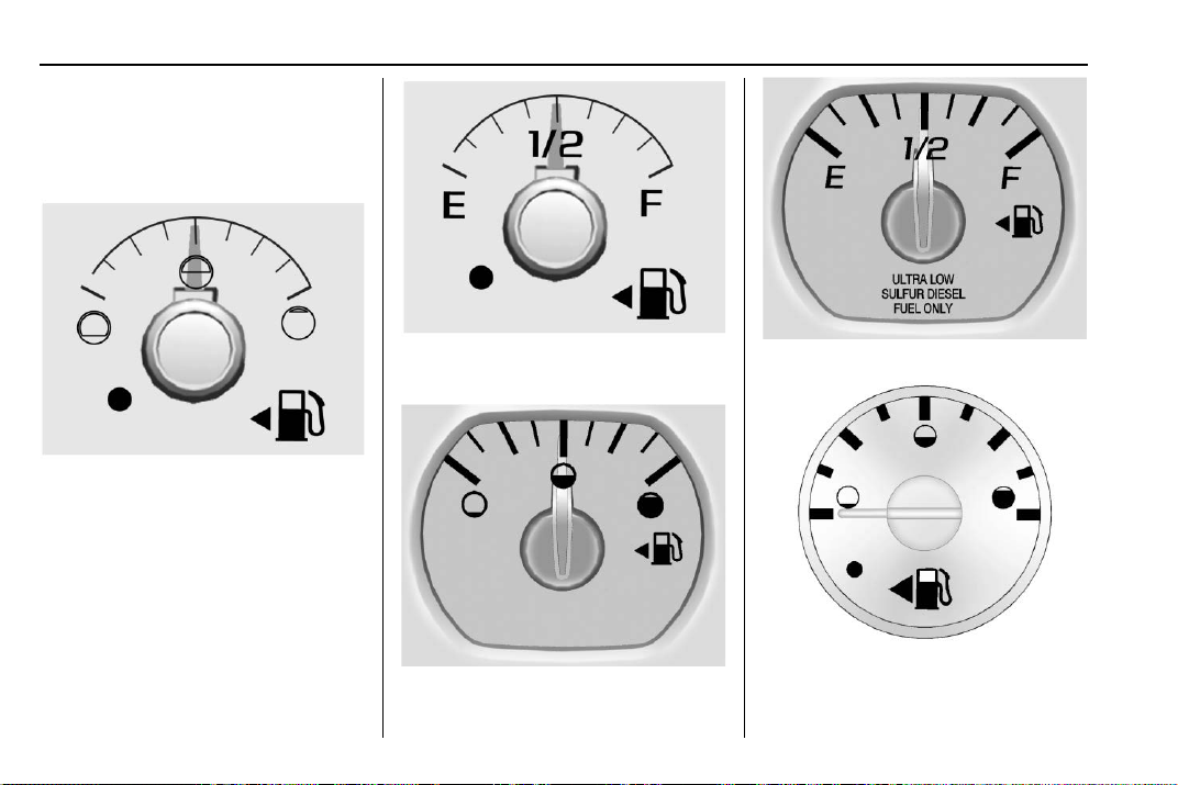
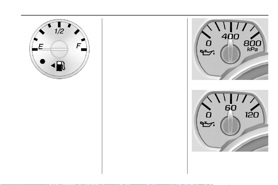
Fuel Gauge
English Base Level 4-Cylinder
Pickup Shown, Uplevel Similar
Metric Base Level 4-Cylinder
Pickup Shown, Uplevel Similar
Metric 8-Cylinder Pickup Models
English 8-Cylinder Pickup Models
Metric Van Models
Page 18
Chevrolet/GMC Duramax Diesel Supplement (GMNA-Localizing-U.S./Canada-
11354421) - 2018 - CRC - 10/10/17
.
It takes a little more or less fuel
to fill up than the fuel gauge
indicated. For example, the
gauge may have indicated the
tank was half full, but it actually
took a little more or less than
half the tank's capacity to fill
the tank.
.
The gauge moves a little while
turning a corner or speeding up.
.
The gauge does not go back to
English Van Models
When the ignition is on, the fuel
gauge shows approximately how
much fuel the vehicle has left in the
tank. The gauge will first indicate
E (Empty) before the vehicle is out
of fuel, but the vehicle's fuel tank
should be filled soon.
An arrow on the fuel gauge
indicates the side of the vehicle the
fuel door is on.
Listed are four situations customers
may experience with the fuel gauge:
.
At the gas station, the fuel pump
shuts off before the gauge reads
F (Full).
E (Empty) when the ignition is
turned off.
None of these indicate a problem
with the fuel gauge.
For information on how to fill the fuel
tank, see Filling the Tank 0 56.
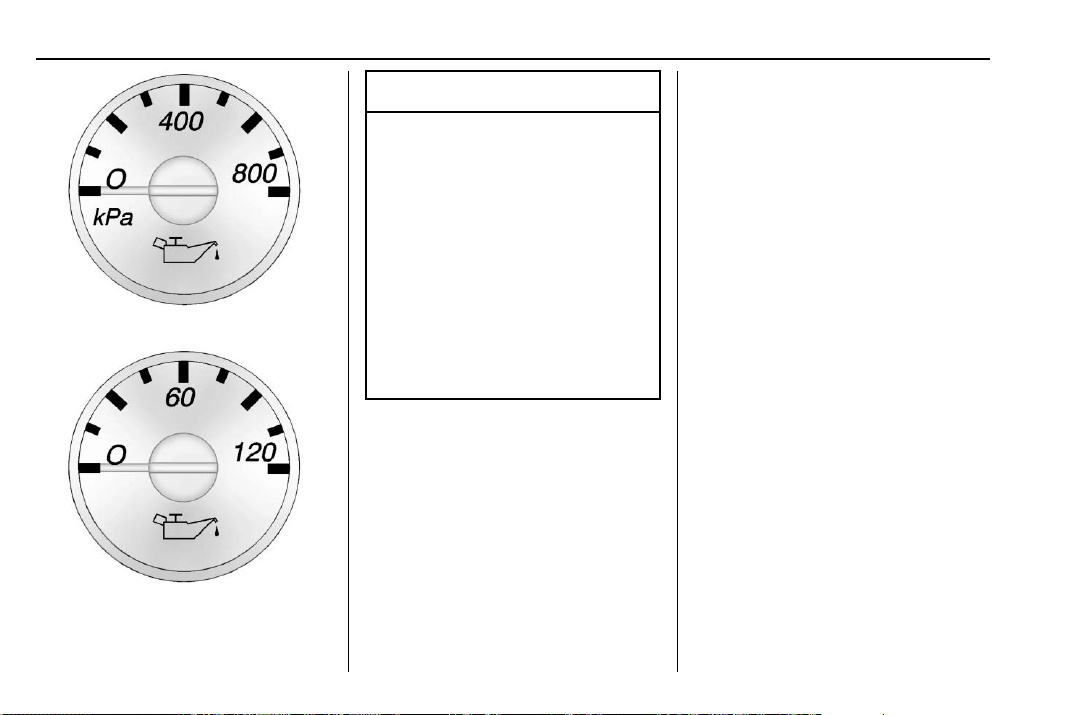
Engine Oil Pressure Gauge
4-Cylinder Pickup Models
See “Oil Pressure” under “Driver
Information Center (DIC)” in the
owner’s manual.
Instruments and Controls 17
Metric 8-Cylinder Pickup Models
English 8-Cylinder Pickup Models
Page 19
Chevrolet/GMC Duramax Diesel Supplement (GMNA-Localizing-U.S./Canada-
11354421) - 2018 - CRC - 10/10/17
18 Instruments and Controls
Caution
Lack of proper engine oil
maintenance can damage the
engine. Driving with the engine oil
low can also damage the engine.
The repairs would not be covered
by the vehicle warranty. Check
the oil level as soon as possible.
Add oil if required, but if the oil
level is within the operating range
Metric Van Models
English Van Models
and the oil pressure is still low,
have the vehicle serviced. Always
follow the maintenance schedule
for changing engine oil.
The engine oil pressure gauge
reads in kPa (kilopascals) or psi
(pounds per square inch) when the
engine is running. Oil pressure may
vary with engine speed, outside
temperature, and oil viscosity.
If readings are outside the normal
operating range, the low oil
pressure message may display on
the Driver Information Center (DIC),
or for vehicles without a DIC the oil
pressure light will come on. If the oil
pressure message or light comes
on, check the oil level immediately.
Do not operate the engine with the
oil pressure warning light on or an
ENGINE OIL LOW ADD OIL
message displayed.
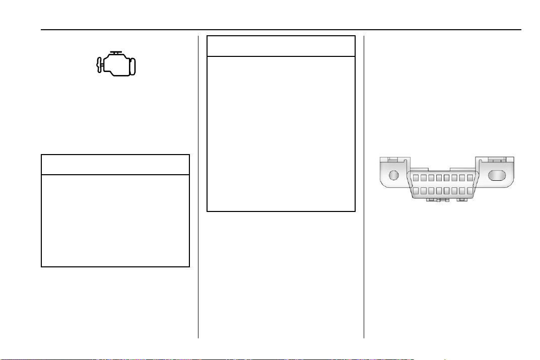
Malfunction Indicator Lamp (Check Engine Light)
This light is part of the vehicle’s
emission control on-board
diagnostic system. If this light is on
while the engine is running, a
malfunction has been detected and
the vehicle may require service. The
light should come on to show that it
is working when the ignition is on
with the engine not running. See
“Ignition Positions” in the owner’s
manual.
This light may also come on when
the system has detected a problem
with the Diesel Exhaust Fluid (DEF)
management system. See Diesel
Exhaust Fluid 0 37.
Page 20
Chevrolet/GMC Duramax Diesel Supplement (GMNA-Localizing-U.S./Canada-
11354421) - 2018 - CRC - 10/10/17
Modifications to the engine,
transmission, exhaust, intake,
or fuel system, or the use of
Malfunctions are often indicated by
the system before any problem is
noticeable. Being aware of the light
and seeking service promptly when
it comes on may prevent damage.
Caution
If the vehicle is driven continually
with this light on, the emission
control system may not work as
well, the fuel economy may be
lower, and the vehicle may not
run smoothly. This could lead to
costly repairs that might not be
covered by the vehicle warranty.
replacement tires that do not
meet the original tire
specifications, can cause this light
to come on. This could lead to
costly repairs not covered by the
vehicle warranty. This could also
affect the vehicle’s ability to pass
an Emissions Inspection/
Maintenance test. See
Accessories and Modifications
0 84.
When the light is on, a malfunction
has been detected. Diagnosis and
service may be required.
Poor fuel quality can cause
inefficient engine operation and poor
driveability, which may go away
once the engine is warmed up.
If this occurs, change the fuel brand.
It may require at least one full tank
of the proper fuel to turn the light off.
See Fuel for Diesel Engines 0 45.
Caution
Instruments and Controls 19
If the light remains on, see your
dealer.
Emissions Inspection and
Maintenance Programs
If the vehicle requires an Emissions
Inspection/Maintenance test, the
test equipment will likely connect to
the vehicle's Data Link
Connector (DLC).
The DLC is under the instrument
panel to the left of the steering
wheel. Connecting devices that are
not used to perform an Emissions
Inspection/Maintenance test or to
service the vehicle may affect
vehicle operation. See “Add-On
Electrical Equipment” in the owner’s
manual. See your dealer if
assistance is needed.
Page 21
Chevrolet/GMC Duramax Diesel Supplement (GMNA-Localizing-U.S./Canada-
11354421) - 2018 - CRC - 10/10/17
20 Instruments and Controls
The vehicle may not pass
inspection if:
.
The light is on when the engine
is running.
.
The light does not come on
when the ignition is on with the
engine not running.
.
Critical emission control systems
have not been completely
diagnosed. If this happens, the
vehicle would not be ready for
inspection and might require
several days of routine driving
before the system is ready for
inspection. This can happen if
the 12-volt battery has recently
been replaced or run down, or if
the vehicle has recently been
serviced.
See your dealer if the vehicle will
not pass or cannot be made ready
for the test.
Wait-to-Start Light
This light comes on briefly while
starting the engine, as a check to
show the light is working.
If the wait-to-start light comes on,
the glow plug system is required
and operating. Wait until the light
turns off before starting the engine.
This light may not come on in warm
temperatures.
The fast warm-up glow plug system
makes the wait-to-start light stay on
for a shorter amount of time than
most diesel engines.
See Starting the Diesel Engine 0 24.
Diesel Exhaust Fluid (DEF) Warning Light
This light, a Driver Information
Center (DIC) message, and a chime
come on when there is an issue with
the Diesel Exhaust Fluid.
If the DEF level has not been
corrected, the light will continue to
flash when the vehicle is started.
The vehicle's speed may also be
limited.
Also see Diesel Exhaust Fluid 0 37.
Page 22

Chevrolet/GMC Duramax Diesel Supplement (GMNA-Localizing-U.S./Canada-
11354421) - 2018 - CRC - 10/10/17
Power Take-Off Light
Information Displays
(Chassis Cab Only)
Driver Information Center (DIC)
The DIC is in the instrument cluster.
The DIC comes on when the ignition
is on.
Chassis Cab
The vehicle may have a Power
Take-Off (PTO) light. Under normal
operating conditions, the PTO light
will remain on throughout the PTO
operating cycle. If all conditions
required to engage PTO have not
been met when enabling PTO, the
PTO light will turn on, then turn off
after one second. See Power
Take-Off (PTO) 0 66.
A Duramax diesel vehicle may have
the following additional DIC menu
items:
Exhaust Fluid Level : The Diesel
Exhaust Fluid (DEF) level will be
displayed as either OK, XX%,
or LOW.
When LOW appears on the display,
add DEF as soon as possible. See
Diesel Exhaust Fluid 0 37.
Fuel Filter Life Remaining : This
display shows an estimate of the
fuel filter's remaining useful life.
If 90% Fuel Filter Life Remaining is
displayed, it means 90% of the
current fuel filter life remains. The
fuel filter life system will alert when
to change the fuel filter on a
schedule consistent with your
driving conditions.
Instruments and Controls 21
When the remaining fuel filter life is
low, the CHANGE FUEL FILTER
message will appear on the display.
Change the fuel filter as soon as
possible.
Fuel Filter Life Reset : Reset the
Fuel Filter Life Remaining display
after each fuel filter change. It will
not reset itself. Also, be careful not
to reset the display at any time other
than when the fuel filter has just
been changed because it cannot be
reset accurately until the next fuel
filter change. The fuel filter life will
change to 100% when the system
has been reset. To reset the system,
press and hold the set/reset button,
or the trip odometer reset stem if
there are no DIC buttons, for
two seconds while Fuel Filter Life
Remaining is displayed on the DIC.
Page 23

Chevrolet/GMC Duramax Diesel Supplement (GMNA-Localizing-U.S./Canada-
11354421) - 2018 - CRC - 10/10/17
22 Instruments and Controls
Vehicle Personalization
Vehicle Personalization (Pickup Models)
Use the audio system controls to
access the personalization menus
for customizing vehicle features.
The following features may be
available on some vehicles with a
diesel engine. See “Vehicle
Personalization” in the owner’s
manual for additional vehicle
personalizations.
System Controls
1. Turn the ignition on without the
engine running and place the
vehicle in P (Park).
To avoid excessive drain on
the battery, turn the
headlamps off.
2. Press the MENU knob on the
radio.
3. Turn the MENU knob to scroll
to SETTINGS, then press the
MENU knob.
4. Turn the MENU knob to scroll
to Vehicle, then press the
MENU knob.
5. Turn the MENU knob to scroll
to the desired menu, then
press the MENU knob.
If equipped, these features may be
selected using the infotainment
display.
Vehicle
Select and the following may
display:
.
Climate and Air Quality
.
Power Take-Off (PTO)
Climate and Air Quality
Select and the following may
display:
.
Elevated Idle
Elevated Idle
This allows the feature to be turned
on and off. See “Elevated Idle” in
Starting the Diesel Engine 0 24.
Select Off or On.
Power Take-Off (PTO) (If
Equipped)
There may be additional features
that can be customized for the PTO.
See Power Take-Off (PTO) 0 66.
See your dealer to enable these
features.
Feature Settings Menu Items
Press the MENU knob to select the
desired setting.
.
Standby Speed
.
Set 1 Speed
.
Set 2 Speed
.
Tap Step Speed
.
Shutdown Time
Turn the MENU knob to scroll to
one of the following menu
selections:
Page 24

Chevrolet/GMC Duramax Diesel Supplement (GMNA-Localizing-U.S./Canada-
11354421) - 2018 - CRC - 10/10/17
PTO STANDBY SPEED
This feature allows for modifying the
PTO Standby Speed.
Turn the MENU knob to the desired
setting. Press the MENU knob to
select the desired setting.
PTO SET 1 SPEED
This feature is available if the
vehicle is configured for Stationary
Preset PTO, and allows the
selection of the PTO set 1 speed.
Turn the MENU knob to the desired
PTO Standby Set 1 setting. Press
the MENU knob to select the
desired setting.
PTO SET 2 SPEED
This feature is available if the
vehicle is configured for Stationary
Preset PTO, and allows the
selection of the PTO set 2 speed.
Turn the MENU knob to the desired
PTO Standby Set 2 setting. Press
the MENU knob to select the
desired setting.
PTO TAP STEP SPEED
This feature is available if the
vehicle is configured for Stationary
Variable or Mobile PTO, and allows
the selection of the PTO tap step
speed.
Turn the MENU knob to the desired
PTO Tap Step Speed setting. Press
the MENU knob to select the
desired setting.
PTO SHUTDOWN TIME
This feature is available if the
vehicle is configured for Stationary
Preset or Stationary Variable PTO,
and allows the selection of the PTO
shutdown time.
Turn the MENU knob to the desired
PTO Shutdown Time setting. Press
the MENU knob to select the
desired setting.
Vehicle Personalization (Van Models)
This vehicle may have
customization capabilities that allow
you to program certain features to
one preferred setting. Customization
Instruments and Controls 23
features can only be programmed to
one setting on the vehicle and
cannot be programmed to a
preferred setting for two different
drivers.
A Duramax diesel vehicle may have
the following additional vehicle
personalization items:
Feature Settings Menu Items
The following are customization
features that allow you to program
settings to the vehicle:
ELEVATED IDLE
This feature allows you to turn on or
off Elevated Idle.
U until ELEVATED IDLE
Press
appears on the DIC display.
Press
V once to access the settings
for this feature. Then press
scroll through OFF, ON, or NO
CHANGE. To select a setting, press
U to
V while the desired setting is
displayed on the DIC.
Page 25

Chevrolet/GMC Duramax Diesel Supplement (GMNA-Localizing-U.S./Canada-
11354421) - 2018 - CRC - 10/10/17
24 Driving and Operating
Driving and Operating
Starting and Operating
Starting the Diesel Engine . . . . . 24
Winter Cover . . . . . . . . . . . . . . . . . . . 27
Engine Heater . . . . . . . . . . . . . . . . . 31
Fuel Operated Heater (FOH)
(Van Models Only) . . . . . . . . . . . 33
Parking over Things
That Burn . . . . . . . . . . . . . . . . . . . . 34
Diesel Particulate Filter
Diesel Particulate Filter . . . . . . . . 34
Diesel Exhaust Fluid
Diesel Exhaust Fluid . . . . . . . . . . . 37
Brakes
Exhaust Brake . . . . . . . . . . . . . . . . . 44
Fuel
Fuel for Diesel Engines . . . . . . . . 45
What Fuel to Use in
the U.S. . . . . . . . . . . . . . . . . . . . . . . 46
What Fuel to Use in Canada . . . 47
Biodiesel . . . . . . . . . . . . . . . . . . . . . . . 47
Cold Weather Operation . . . . . . . 49
Water in Fuel . . . . . . . . . . . . . . . . . . 50
Running Out of Fuel . . . . . . . . . . . 53
Fuel Filter Replacement . . . . . . . 54
Filling the Tank . . . . . . . . . . . . . . . . 56
Filling a Portable Fuel
Container . . . . . . . . . . . . . . . . . . . . . 58
Trailer Towing
Trailer Towing . . . . . . . . . . . . . . . . . . 58
Conversions and Add-Ons
Power Take-Off (PTO) . . . . . . . . . 66
Starting and
Operating
Starting the Diesel Engine
The diesel engine starts differently
than a gasoline engine.
Caution
If the steering wheel is turned
until it reaches the end of its
travel, and is held in that position
while starting the vehicle, damage
may occur to the hydraulic power
steering system and there may be
loss of power steering assist.
Move the shift lever to P (Park) or
N (Neutral). To restart the engine
when the vehicle is already moving,
use N (Neutral) only.
Page 26
Chevrolet/GMC Duramax Diesel Supplement (GMNA-Localizing-U.S./Canada-
11354421) - 2018 - CRC - 10/10/17
Caution
Do not try to shift to P (Park) if the
vehicle is moving. If you do, you
could damage the transmission.
Shift to P (Park) only when the
vehicle is stopped.
Starting the Engine
1. Turn the ignition key to
ON/RUN.
Observe the wait-to-start light.
See Wait-to-Start Light 0 20.
This light may not come on if
the engine is warm.
2. If the wait-to-start light is on,
wait until this light goes off.
Turn the ignition key to START,
then release the ignition key.
The engine will continue to
crank until the engine starts.
The engine has a fast warm-up
glow plug system. The
wait-to-start light will illuminate
for a much shorter time than
most diesel engines, due to the
rapid heating of the glow plug
system.
If the wait-to-start light stays on
after starting the vehicle, the
vehicle may not run properly.
Have the vehicle serviced
right away.
3. If the engine does not start
after 15 seconds of cranking,
turn the ignition switch to
LOCK/OFF. Wait one minute
for the cranking motor to cool,
then try the same steps again.
If you are trying to start the engine
after you have run out of fuel, follow
the steps in Running Out of Fuel
0 53.
When the engine is cold, let it run
for a few minutes before driving.
This lets oil pressure build up. The
engine will sound louder when it
is cold.
Caution
Driving and Operating 25
For turbo protection, engine power
at speeds above idle may be limited
if the engine is cold. This protection
can last up to a maximum of
40 seconds at extreme cold coolant
and ambient temperatures.
Cold Weather Starting
Use the recommended engine oil
when the outside temperature
drops below freezing. See Engine
Oil 0 91. When the outside
temperature drops below –18 °C
(0 °F), use of the engine coolant
heater is recommended.
If you experience longer cranking
times, notice an unusual amount of
exhaust smoke, or are at higher
elevations (over 2 135 m or 7,000 ft),
you may use the engine coolant
heater. See Engine Heater 0 31.
See Fuel for Diesel Engines 0 45 for
information on what fuel to use in
cold weather.
If the Diesel Engine Will Not
Start
If the vehicle runs out of fuel, see
Running Out of Fuel 0 53.
Page 27

Chevrolet/GMC Duramax Diesel Supplement (GMNA-Localizing-U.S./Canada-
11354421) - 2018 - CRC - 10/10/17
26 Driving and Operating
If the vehicle is not out of fuel, and
the engine will not start:
Turn the ignition key to ON/RUN.
After the wait-to-start light goes off,
turn the ignition key to START.
If the light does not go off, wait a
few seconds, then try starting the
engine again. See your dealer as
soon as you can for a starting
system check.
If the light comes on and then goes
off and you know the batteries are
charged, but the engine still will not
start, the vehicle needs service.
If the light does not come on when
the engine is cold, the vehicle
needs service.
If the batteries do not have enough
charge to start the engine, see
“Battery” in the owner manual.
Check that the correct engine oil
has been used and changed at
appropriate intervals. If the wrong oil
is used, the engine may be harder
to start.
Be sure you are using the proper
fuel for existing weather conditions.
See Fuel for Diesel Engines 0 45.
If the engine starts, runs a short
time, then stops, the vehicle needs
service.
Warning
{
Do not use gasoline or starting
aids, such as ether, in the air
intake. They could damage the
engine, which may not be
covered by the vehicle warranty.
They could also cause a fire,
which could cause serious
personal injury.
Engine Idle Variations
Under certain conditions the engine
idle speed can vary or be elevated.
Change in idle speed is normal and
does not indicate a problem. Normal
conditions that can raise idle speed
are low voltage, DPF regeneration,
air conditioning compressor loads,
and engine warmup. These speeds
can range from approximately 600
to 1000 rpm.
Elevated Idle
The engine has a cold temperature
high idle feature which elevates the
engine idle speed from base idle to
1050 to 1100 rpm for pickup models
or 1200 rpm for van models when
outside temperatures are below 0 °C
(32 °F), and the engine coolant
temperature is below 65 °C (150 °F).
This feature enhances heater
performance by raising the engine
coolant temperature faster.
To turn this feature on or off on
pickup models, see Vehicle
Personalization (Pickup Models)
0 22 or Vehicle Personalization (Van
Models) 0 23.
On van models, this feature can be
turned on and off using the DIC
buttons.
When the engine is started, it will
slowly ramp up to the high idle
speed after a delay of a few
seconds up to approximately
Page 28

Chevrolet/GMC Duramax Diesel Supplement (GMNA-Localizing-U.S./Canada-
11354421) - 2018 - CRC - 10/10/17
two minutes. For this method to
work properly there must be no
throttle or brake pedal faults.
The engine idle speed will return to
normal once the following conditions
are met:
.
Engine coolant temperature
reaches 65 °C (150 °F).
.
Air intake temperature reaches
0 °C (32 °F).
The high idle speed will be
temporarily interrupted and the
engine speed will return to normal if
any of the following conditions
occur:
.
The brake pedal is applied.
.
The accelerator pedal is
pressed.
.
The transmission is shifted out
of P (Park) or N (Neutral).
.
Vehicle speed is detected.
Once these inputs are removed, the
engine idle speed will slowly ramp
back up to high idle after the normal
delay, if the conditions for engine
coolant temperature and air intake
temperature are still met.
Fast Idle Control (Vans and
8-Cylinder Pickups Only)
The vehicle may have this system
which can be used to increase the
engine idle speed.
Fast Idle control will be enabled
when the following conditions
are met:
.
The parking brake is set.
.
The transmission is in P (Park)
or N (Neutral).
.
The vehicle speed is about
0 km/h (0 mph).
.
The cruise control Set switch is
pressed and released for Preset
Fast Idle Speed (1200 rpm).
Fast Idle control will be disabled
when one or more of the following
conditions occur:
.
The cruise control Set switch is
pressed and released. See
“Cruise Control” in the owner
manual.
Driving and Operating 27
.
The cruise control Cancel switch
is pressed.
.
The brake pedal is pressed.
.
The transmission is shifted out
of P (Park) or N (Neutral).
.
The parking brake is released.
.
The vehicle speed is not
0 km/h (0 mph).
On vans, when fast idle is active, a
FAST IDLE ON message will be
displayed in the DIC.
Winter Cover
4-Cylinder Pickups
Do not use a winter cover on
4-cylinder pickups.
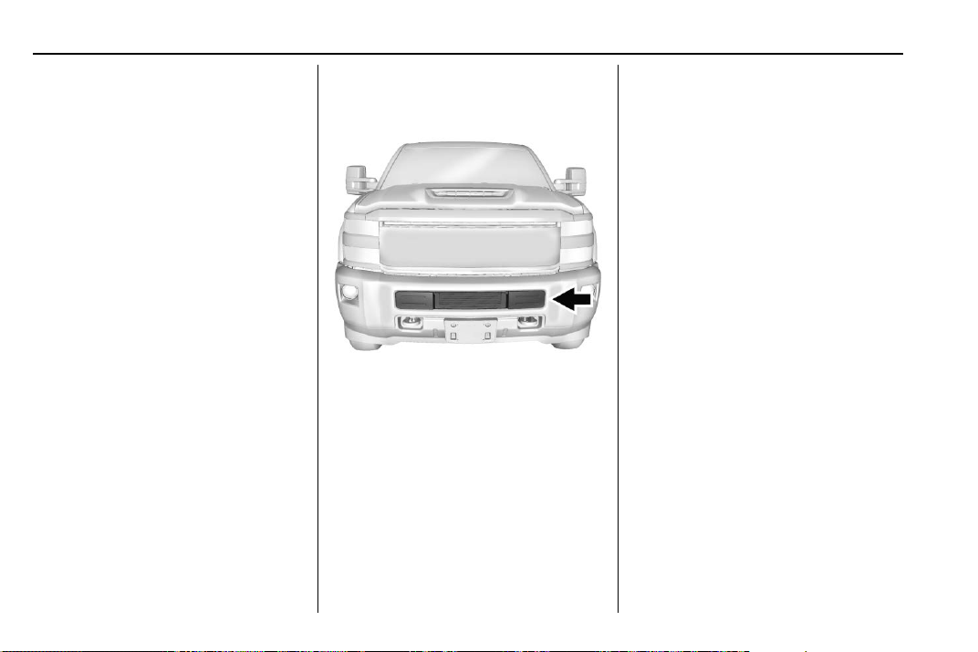
Vans and 8-Cylinder Pickups Only
If equipped, the winter cover can be
used to enhance heater
performance in extremely cold
conditions below −18 °C (0 °F). The
winter cover installs over the grille
and restricts airflow to the engine
compartment.
Page 29
Chevrolet/GMC Duramax Diesel Supplement (GMNA-Localizing-U.S./Canada-
11354421) - 2018 - CRC - 10/10/17
28 Driving and Operating
For vehicles that did not come with
a winter cover, a GM winter cover
can be purchased. See your dealer
for additional information.
When the winter cover is in use, the
heater, ventilation, and air
conditioning AUTO mode may not
function properly. Use the manual
settings for comfort.
Usage Guidelines
The winter cover should only be
used while operating the vehicle in
extremely cold temperatures or in
heavy snow for extended periods. In
these temperatures, the vehicle
does not need a large amount of air
to properly cool the engine. When
more airflow is required to cool the
vehicle, the winter cover should not
be used. The following usage
guidelines will allow adequate
airflow for proper radiator and air
cooler performance:
.
Do not use the winter cover if
towing a trailer. The vehicle may
overheat if the radiator is
covered while towing.
.
Do not use the winter cover if a
snow plow is mounted on the
truck.
.
Do not cover the opening in the
front bumper.
.
Do not modify the cover. The
winter cover does not cover
some sections of the front of the
vehicle to provide enough
airflow.
.
When the winter cover is used,
the outside air temperature
display may not function
properly.
.
Keep the underside of the winter
cover as clean as possible.
Remove monthly or as
necessary and clean away dust
and debris.
.
Use only a mild soap to clean.
Do not use harsh soap, strong
detergents, or vinyl protectant/
sealant type products as they
may damage the special finish.
Allow the winter cover to dry
completely before reinstalling.
Installation Instructions
When first trying to fit the cover, it
may appear to be undersized but
will stretch during installation to
ensure a tight fit. The initial
installation of the cover is best
performed when the winter cover
is warm.
Page 30
Chevrolet/GMC Duramax Diesel Supplement (GMNA-Localizing-U.S./Canada-
11354421) - 2018 - CRC - 10/10/17
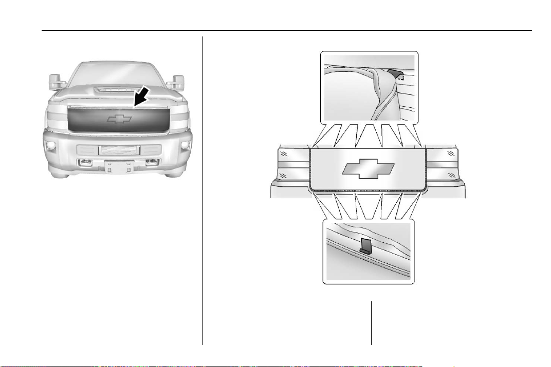
Installation (Chevrolet Pickup)
1. The white label must be at the
top and back of the cover.
Driving and Operating 29
2. Starting in the middle, attach
fastening points as illustrated.
3. To remove, reverse the steps
listed previously.
Page 31

Chevrolet/GMC Duramax Diesel Supplement (GMNA-Localizing-U.S./Canada-
11354421) - 2018 - CRC - 10/10/17
30 Driving and Operating
Installation (GMC Pickup)
1. The white label must be at the
top and back of the cover.
2. Starting in the middle, attach
fastening points as illustrated.
3. To remove, reverse the steps
listed previously.
Installation (Van Models)
1. Open the hood and secure it
with the prop rod.
Page 32

Chevrolet/GMC Duramax Diesel Supplement (GMNA-Localizing-U.S./Canada-
11354421) - 2018 - CRC - 10/10/17
2. Hook the five J-clips to the
bottom edge of the grille.
3. Hook the top center J-clip by
the hood latch.
4. Attach the metal hooks, one
each at the top corners.
Driving and Operating 31
5. To remove the winter cover,
reverse the steps listed
previously.
Engine Heater
Warning
{
Do not plug in the engine block
heater while the vehicle is parked
in a garage or under a carport.
Property damage or personal
injury may result. Always park the
vehicle in a clear open area away
from buildings or structures.
If equipped, the engine heater can
provide easier starting in cold
weather conditions at or below
−18 °C (0 °F). The engine heater
should be plugged in at least four
hours before starting.
To Use the Engine Heater
1. Turn off the engine.
Page 33

Chevrolet/GMC Duramax Diesel Supplement (GMNA-Localizing-U.S./Canada-
11354421) - 2018 - CRC - 10/10/17
32 Driving and Operating
8-Cylinder Pickups
2. Open the hood and unwrap the
3. Clean and dry the heater cord
4-Cylinder Pickups
4-Cylinder Vans
electrical cord. For 8-cylinder
pickups, the cord is in the
engine compartment, on the
driver side near the battery. For
4-cylinder pickups, the cord is
in the engine compartment, on
the driver side behind the
battery, and on the passenger
side for 4-cylinder vans.
and connector ends. Check the
heater cord for damage. If it is
damaged, do not use it. See
your dealer for a replacement.
Inspect the cord for damage
yearly.
4. Plug it into a normal, grounded
110-volt AC outlet.
Warning
{
Improper use of the heater cord
or an extension cord can damage
the cord and may result in
overheating and fire.
.
Plug the cord into a
three-prong electrical utility
receptacle that is protected
by a ground fault detection
function. An ungrounded
outlet could cause an
electric shock.
.
Use a weatherproof,
heavy-duty, 15 amp-rated
extension cord if needed.
Failure to use the
recommended extension
cord in good operating
condition, or using a
damaged heater or
(Continued)
Page 34

Chevrolet/GMC Duramax Diesel Supplement (GMNA-Localizing-U.S./Canada-
11354421) - 2018 - CRC - 10/10/17
Warning (Continued)
extension cord, could make
it overheat and cause a fire,
property damage, electric
shock, and injury.
.
Do not operate the vehicle
with the heater cord
permanently attached to the
vehicle. Possible heater
cord and thermostat
damage could occur.
.
While in use, do not let the
heater cord touch vehicle
parts or sharp edges. Never
close the hood on the
heater cord.
.
Before starting the vehicle,
unplug the cord, reattach
the cover to the plug, and
securely fasten the cord.
Keep the cord away from
any moving parts.
5. Before starting the engine, be
sure to unplug and store the
cord as it was before to keep it
away from moving engine parts
and prevent damage.
The length of time the heater should
remain plugged in depends on the
outside temperature. You may wish
to use the coolant heater to improve
ease of starting at temperatures
between −18 °C (0 °F) and
−29 °C (−20 °F). Keep the coolant
heater plugged in for a minimum of
four hours. At temperatures below
−29 °C (−20 °F), the coolant heater
should remain plugged in for at least
eight hours. Be sure to store the
cord before starting the engine. See
Fuel for Diesel Engines 0 45 for
information on what fuel to use in
cold weather.
Do not use the engine heater
continuously. This could damage
the engine heater and may cause
a fire. Always unplug the engine
heater after use.
Caution
Driving and Operating 33
Fuel Operated Heater (FOH) (Van Models Only)
If equipped, the FOH will enhance
heater performance and will reduce
the amount of time it takes to warm
the inside of the vehicle in cold
conditions below or equal to 4 °C
(39 °F).
The FOH is installed on the frame
rail on the driver side of the vehicle
and uses diesel fuel to heat the
engine coolant, which warms up the
passenger cabin air.
Page 35

Chevrolet/GMC Duramax Diesel Supplement (GMNA-Localizing-U.S./Canada-
11354421) - 2018 - CRC - 10/10/17
34 Driving and Operating
The FOH will turn on if all of the
following conditions exist:
.
Outside air temperature is below
or equal to 4 °C (39 °F).
.
Fuel level is greater or equal to
12.5% of the total fuel tank
volume.
.
The engine is running.
.
Coolant temperature is less than
70 °C (158 °F).
Parking over Things That Burn
Warning
{
Things that can burn could touch
hot exhaust parts under the
vehicle and ignite. Do not park
over papers, leaves, dry grass,
or other things that can burn.
Diesel Particulate Filter
The vehicle has a Diesel Particulate
Filter (DPF) as part of the exhaust
system to reduce vehicle emissions.
The DPF requires a unique exhaust
tailpipe with an exhaust cooler. The
exhaust cooler mixes air with the
exhaust to lower the temperature
before it leaves the tailpipe.
The DPF, the tailpipe, or other
exhaust system components must
not be altered. Inspect regularly and
clean any mud or dirt from the
exhaust cooler, especially where the
exhaust cooler connects to the
tailpipe and the openings where
fresh air enters the cooler.
The DPF will clean itself as part of
normal operation. Several factors
including fuel consumed, hours of
engine operation, and miles driven
are monitored by the Engine Control
Module (ECM). The self-cleaning
occurs approximately once per tank
of fuel.
Caution
Permanent damage can occur to
the DPF or related components if
the required Ultra Low Sulfur
Diesel (15 ppm sulfur maximum)
or low ash CJ-4 engine oil is not
used. This damage would not be
covered by the vehicle warranty.
Under certain driving conditions,
such as stop-and-go traffic, the filter
cannot clean itself. A message
comes on when the DPF is dirty and
needs to perform a self cleaning.
For the filter to clean itself, the
vehicle must be driven above
50 km/h (30 mph) until the message
goes off. This will take about
30 minutes.
Warning
{
During DPF self cleaning or
during extended idling in P (Park),
the exhaust system and exhaust
(Continued)
Page 36

Chevrolet/GMC Duramax Diesel Supplement (GMNA-Localizing-U.S./Canada-
11354421) - 2018 - CRC - 10/10/17
Warning (Continued)
gases are very hot. Things that
burn could touch hot exhaust
parts under the vehicle and ignite.
You or others could be burned.
Do not park, or idle for an
extended period of time, near or
over papers, leaves, dry grass,
or other things that can burn.
Keep the exhaust area clear of
material that could ignite or burn.
See Parking over Things That
Burn 0 34.
Caution
Extended idle should be avoided
because the DPF system is not
capable of self cleaning at idle.
During extended idle operation,
monitor the instrument cluster
telltale lights and Driver
Information Center for messages
and take appropriate indicated
(Continued)
Caution (Continued)
action. Continued idling with the
warning light/message on could
cause irreversible damage to the
DPF requiring repair and possible
replacement that might not be
covered by the vehicle warranty.
You will also notice a change in the
exhaust sound and engine idle
speed. This is normal.
If you continue to drive with the DPF
warning message on and the
exhaust filter is not cleaned as
required, the malfunction indicator
lamp and the ENGINE POWER IS
REDUCED message will come on
and dealer service is necessary.
See Malfunction Indicator Lamp
(Check Engine Light) 0 18.
Vehicles with the DPF have specific
fuel and engine oil requirements.
See What Fuel to Use in the U.S.
0 46 and Engine Oil 0 91.
Driving and Operating 35
Extended idling in P (Park) can
cause exhaust parts and gases to
become very hot. Keep the exhaust
area clear of material that could
ignite or burn. See Parking over
Things That Burn 0 34.
If equipped with Power
Take-Off (PTO), monitor the
instrument cluster for lights related
to the DPF.
See Accessories and Modifications
0 84 for important information if you
are considering adding accessories
or modifying the vehicle.
Manual Regeneration of Diesel
Particulate Filter
This feature is only available on
Fleet and Commercial vehicles. To
verify that the vehicle has this
feature, refer to the Vehicle Service
Parts Identification label (SPID) for
RPO code FPF or see
www.gmupfitter.com to contact the
GM Upfitter Integration Group for
assistance.
Page 37

Chevrolet/GMC Duramax Diesel Supplement (GMNA-Localizing-U.S./Canada-
11354421) - 2018 - CRC - 10/10/17
36 Driving and Operating
If equipped, this feature allows for
manual cleaning/regeneration of the
Diesel Particulate Filter (DPF) when
it is unable to clean itself. It may be
necessary to perform a manual
regeneration if driving conditions —
such as extended slow speed,
stop-and-go traffic, extended idles,
short drive cycles, or stationary PTO
operation — prevent DPF
self-cleaning.
Manual regeneration can only be
used when the DPF has become at
least 90% full. At 100% full, it will
attempt to automatically self-clean if
proper driving conditions are met.
The DPF will clean itself if the
vehicle can be driven above
50 km/h (30 mph) for about
30 minutes.
A Driver Information Center (DIC)
message displays when manual
regeneration is possible.
Scroll through the DIC pages to find
the Exhaust Cleaning menu.
Depending on whether the vehicle
has a base or uplevel cluster, it may
be under the Settings menu.
If the vehicle cannot be stopped
when the DIC message first
indicates cleaning is available,
automatic self-cleaning may have
begun. If conditions cannot be met
for self-cleaning to complete, and
manual regeneration is selected, it
may take up to four minutes for the
system to switch to manual
regeneration. When the switch
occurs, a DIC message prompts to
start the cleaning process.
Warning: The exhaust system and
exhaust gases get very hot during a
manual regeneration. Things that
burn could touch hot exhaust parts
under the vehicle and may catch
fire. You or others could be burned.
Do not leave the vehicle unattended
during a manual regeneration.
Before starting the manual
regeneration, make sure all of the
following safety conditions are met:
.
The vehicle is parked on level
ground, away from any
flammable materials.
.
The vehicle is parked outdoors,
away from any walls or
buildings.
.
The vehicle is at least 3 m (10 ft)
from any obstructions or
materials that may combust
or melt.
.
The shift lever is in P (Park).
.
The fuel tank is at least
one-eighth full
.
All fluids are at the proper level.
.
No diagnostic trouble codes
have been set, and the
malfunction indicator lamp is
not on.
.
The engine coolant temperature
is above 71 °C (160 °F).
After making sure all of the safety
conditions have been met, press the
trip odometer reset stem or <
symbol for the check button> on the
steering wheel control for at least
one second to select Start on the
infotainment display.
Page 38

Chevrolet/GMC Duramax Diesel Supplement (GMNA-Localizing-U.S./Canada-
11354421) - 2018 - CRC - 10/10/17
Follow the instructions in the DIC
messages. Touch ACCEPT to
acknowledge that all of these safety
conditions have been met and to
activate regeneration.
If the infotainment display returns to
the previous screen, then one or
more of the necessary operating
conditions has not been met. If you
cannot determine which condition
has not been met, see
www.gmupfitter.com to contact the
GM Upfitter Integration Group for
assistance.
Continue to follow the instructions in
the DIC messages. Hold the
Exhaust Brake switch on the
instrument panel below the climate
controls for more than
three seconds, and then release it,
to begin the regeneration process.
If the EXHAUST BRAKE ON
message displays, then the switch
was released too soon. Press it
again to turn off the exhaust brake,
then try again when the DIC
message prompts.
When manual regeneration begins,
the engine speed increases, the
engine cooling fan sound increases,
and a DIC message indicates that
cleaning is in progress.
A DIC message will display when
cleaning has completed. The
message will remain as long as
cleaning is not necessary. Cleaning
could take up to 30 minutes. Upon
completion, the engine will return to
normal idle, but exhaust
components will remain hot for
several minutes. Do not move the
vehicle until the exhaust has had
time to cool. Manual regeneration
can be canceled at any time by
pressing the brake pedal or turning
the engine off. Unusual noises may
be heard if regeneration is
interrupted.
Driving and Operating 37
Diesel Exhaust Fluid
Warning
{
Diesel Exhaust Fluid (DEF) is
corrosive. Do not allow it to come
in contact with your skin, eyes,
or the finished surfaces of the
vehicle. If exposed, it may cause
skin and eye irritation. Wear skin
and eye protection when
handling. Inhalation may cause
irritation to the upper respiratory
tract. For more safety and storage
information, see the label of the
Diesel Exhaust Fluid container.
Diesel Exhaust Fluid (DEF) is used
with diesel engines to reduce the
amount of regulated emissions
produced. The fluid level in the DEF
tank must be maintained for the
vehicle to run properly. DEF is not a
fuel additive. DEF should not be
mixed with or added to diesel fuel.
DEF freezes when exposed to
Page 39

Chevrolet/GMC Duramax Diesel Supplement (GMNA-Localizing-U.S./Canada-
11354421) - 2018 - CRC - 10/10/17
38 Driving and Operating
temperatures below −11 °C
(12 ° F).For DEF tank capacity see
Capacities and Specifications 0 131.
Locating Diesel Exhaust Fluid
DEF can be purchased at a
Chevrolet or GMC dealer. It can
also be purchased at authorized
vehicle and truck dealerships.
Additionally, some diesel truck
fueling stations or retailers may
have DEF for purchase. For
vehicles with an active OnStar
subscription, OnStar can help to
locate a DEF retailer. See
“Customer Assistance Offices” in
the owner manual for phone
numbers to assist in contacting a
GM dealer. See Recommended
Fluids and Lubricants 0 126.
Filling the DEF Tank
Caution
Use only DEF that is GM
approved, or fluid containing the
API certified or ISO 22241 label.
The use of other fluids could
damage the system, requiring
costly repairs that will not be
covered by the vehicle warranty.
When adding fluid, it is
recommended to fill the DEF tank.
For DEF tank capacity see
Capacities and Specifications 0 131.
Do not overfill the DEF tank. When
fluid reaches the top of the fill pipe,
stop filling.
If you spill DEF on the vehicle while
filling the tank, rinse the area with
water and wipe the surface with a
damp cloth.
DEF Fill–Van Model Shown,
4-Cylinder Pickups Similar
For vans and 4-cylinder pickups, the
DEF fill is behind the fuel fill door.
The DEF cap is blue, and the diesel
cap is green.
The fill tube location for chassis cab
and cutaway vans finished by an
upfitter will vary. Check the upfitter
manual.
Page 40

Chevrolet/GMC Duramax Diesel Supplement (GMNA-Localizing-U.S./Canada-
11354421) - 2018 - CRC - 10/10/17
As the DEF level drops, warnings
will automatically be displayed in the
DIC. DEF level status is available
on the DIC under the vehicle
Information button. See “Exhaust
Fluid Level” in Driver Information
Center (DIC) 0 21.
To avoid vehicle speed limitations,
the DEF tank should be refilled at
the first opportunity after a low
warning indication. If DEF is added
DEF Fill–8-Cylinder Pickups
For 8-cylinder pickups, the DEF fill
is under the hood, on the passenger
side, at the back of the engine
compartment. The DEF cap is blue.
In certain cold conditions, it is
possible to find some frozen DEF in
the DEF fill pipe opening. If this
condition prevents the filling of a
DEF tank, place the vehicle in a
warm garage overnight.
Exhaust Fluid Low
A full DEF tank will last for several
thousand kilometers (miles),
depending on vehicle usage.
before the EXHAUST FLUID
EMPTY REFILL NOW message
appears, it may take several km/mi
for the DIC message to update.
If the vehicle speed has been
limited and DEF has been added, it
may take up to 30 seconds after
engine start with the vehicle
stopped for the EXHAUST FLUID
EMPTY REFILL NOW message to
clear. If the vehicle is driven prior to
the DIC message clearing, the
vehicle speed will still be limited.
If the DIC message clears while
driving, the speed limitation will be
removed gradually.
Driving and Operating 39
If DEF is added under freezing
conditions, additional time may be
required to remove speed limitations
and may require less fluid to fill the
DEF tank.
The following actions describe
strategies required by the U.S.
Environmental Protection Agency
(EPA) and the California Air
Resource Board (CARB). The DEF
messages relate to these strategies.
The EXHAUST FLUID RANGE
message first displays at
approximately 1 600 km (1,000 mi).
This message appears again at
approximately 500 km (300 mi) of
remaining range before the exhaust
fluid tank becomes empty.
Based on driving conditions the
amount needed to fill the tank
will vary.
See the following list for
approximate volume required to fill
the DEF tank when 1 600 km
(1,000 mi) warning appears:
.
Colorado/Canyon - 4-cylinder -
16.5 L (4.5 gal)
Page 41

Chevrolet/GMC Duramax Diesel Supplement (GMNA-Localizing-U.S./Canada-
11354421) - 2018 - CRC - 10/10/17
40 Driving and Operating
.
Silverado/Sierra/Sierra Denali 8-cylinder - 14.5 L (3.8 gal)
.
Express/Savana - 4-cylinder -
14.5 L (3.8 gal)
Below 500 km (300 mi) of range
remaining, these messages will
appear every time the vehicle is
started.
If these warnings are ignored and
the DEF tank becomes empty, the
DIC message displays:
.
For vans and 4-cylinder pickups,
EXHAUST FLUID EMPTY
REFILL NOW - 644 KM (400 MI)
UNTIL 105 KM/H (65 MPH) MAX
SPEED.
.
For 8-cylinder pickups,
EXHAUST FLUID EMPTY
REFILL NOW - 805 KM (500 MI)
UNTIL 105 KM/H (65 MPH) MAX
SPEED.
.
For emergency pickups with
RPO ANM, EXHAUST FLUID
EMPTY REFILL NOW 65 534 KM (40,721 MI) UNTIL
158 KM/H (98 MPH) MAX
SPEED.
The displayed mileage will decrease
as driving continues. A warning light
also comes on.
When the mileage countdown is
zero, the DIC message EXHAUST
FLUID EMPTY REFILL NOW TRANSITIONING TO 105 KM/H
(65 MPH) MAX SPEED displays.
A warning light and a chime also
come on. Vehicle speed will be
reduced to a maximum speed limit
of 105 km/h (65 mph).
After the transition to 105 km/h
(65 mph) is complete, the DIC
message displays:
.
EXHAUST FLUID EMPTY
REFILL NOW - SPEED LIMITED
TO 105 KM/H (65 MPH) –
120 KM (75 MI) UNTIL 89 KM/H
(55 MPH) MAX SPEED.
.
For emergency pickups with
RPO ANM, EXHAUST FLUID
EMPTY REFILL NOW - SPEED
LIMITED TO 158 KM/H
(98 MPH) MAX SPEED.
The displayed mileage will decrease
as driving continues. A warning light
and a chime also come on.
When the mileage countdown is
zero, the DIC message EXHAUST
FLUID EMPTY REFILL NOW TRANSITIONING TO 89 KM/H
(55 MPH) MAX SPEED displays.
A flashing warning light and a chime
also come on. Vehicle speed will be
reduced to a maximum speed limit
of 89 km/h (55 mph).
After the transition to 89 km/h
(55 mph) is complete, the DIC
message EXHAUST FLUID EMPTY
REFILL NOW - SPEED LIMITED
TO 89 KM/H (55 MPH) – 120 KM
(75 MI) UNTIL 8 KM/H (5 MPH) MAX
SPEED displays. The displayed
mileage will decrease as driving
continues. A flashing warning light
and a chime also come on.
When the mileage countdown is
zero, the DIC message EXHAUST
FLUID EMPTY REFILL NOW TRANSITIONING TO 8 KM/H
(5 MPH) MAX SPEED displays.
A flashing warning light and a chime
also come on. Vehicle speed will be
reduced to a maximum speed limit
of 8 km/h (5 mph).
Page 42

Chevrolet/GMC Duramax Diesel Supplement (GMNA-Localizing-U.S./Canada-
11354421) - 2018 - CRC - 10/10/17
After the transition to 8 km/h (5 mph)
is complete, the DIC message
EXHAUST FLUID EMPTY REFILL
NOW - SPEED LIMITED TO 8 KM/H
(5 MPH) displays. A flashing
warning light and a chime also
come on.
It is recommended to fill the DEF
tank. At least 7.6 L (2 gal) of DEF
need to be added to release the
vehicle from the speed limitation.
See Capacities and Specifications
0 131, Diesel Exhaust Fluid (DEF)
Warning Light 0 20, and
Recommended Fluids and
Lubricants 0 126.
Exhaust Fluid Quality Poor
Use only DEF that is GM approved,
or fluid containing the API certified
or ISO 22241 label.
DEF has an expiration date. If the
system detects poor quality,
or contaminated or diluted DEF, the
DIC message displays:
.
EXHAUST FLUID QUALITY
POOR - SEE OWNERS
MANUAL NOW – 160 KM
(99 MI) UNTIL 105 KM/H
(65 MPH) MAX SPEED.
.
For emergency pickups with
RPO ANM, EXHAUST FLUID
QUALITY POOR - SEE
OWNERS MANUAL NOW –
65 534 KM (40,721 MI) UNTIL
158 KM/H (98 MPH) MAX
SPEED.
The displayed mileage will decrease
as driving continues. A warning light
also comes on. Adding fresh DEF to
the system may resolve the
problem, depending on several
factors. If the DIC message persists,
see your dealer or additional DIC
messages may display.
When the mileage countdown is
zero, a DIC message EXHAUST
FLUID QUALITY POOR - SEE
OWNERS MANUAL NOW TRANSITIONING TO 105 KM/H
(65 MPH) MAX SPEED displays.
A warning light and a chime also
Driving and Operating 41
come on. Vehicle speed will be
reduced to a maximum speed limit
of 105 km/h (65 mph).
After the transition to 105 km/h
(65 mph) is complete, the DIC
message displays:
.
EXHAUST FLUID QUALITY
POOR - SEE OWNERS
MANUAL NOW - SPEED
LIMITED TO 105 KM/H
(65 MPH) – 120 KM (75 MI)
UNTIL 89 KM/H (55 MPH) MAX
SPEED.
.
For emergency pickups with
RPO ANM, EXHAUST FLUID
QUALITY POOR - SEE
OWNERS MANUAL NOW SPEED LIMITED TO 158 KM/H
(98 MPH) MAX SPEED.
The displayed mileage will decrease
as driving continues. A warning light
and a chime also come on.
When the mileage countdown is
zero, the DIC message EXHAUST
FLUID QUALITY POOR - SEE
OWNERS MANUAL NOW TRANSITIONING TO 89 KM/H
(55 MPH) MAX SPEED displays.
Page 43

Chevrolet/GMC Duramax Diesel Supplement (GMNA-Localizing-U.S./Canada-
11354421) - 2018 - CRC - 10/10/17
42 Driving and Operating
A flashing warning light and a chime
also come on. Vehicle speed will be
reduced to a maximum speed limit
of 89 km/h (55 mph).
After the transition to 89 km/h
(55 mph) is complete, a DIC
message EXHAUST FLUID
QUALITY POOR - SEE OWNERS
MANUAL NOW - SPEED LIMITED
TO 89 KM/H (55 MPH) – 120 KM
(75 MI) UNTIL 8 KM/H (5 MPH) MAX
SPEED displays. The displayed
mileage will decrease as driving
continues. A flashing warning light
and a chime also come on.
When the mileage countdown is
zero, a DIC message EXHAUST
FLUID QUALITY POOR - SEE
OWNERS MANUAL NOW TRANSITIONING TO 8 KM/H
(5 MPH) MAX SPEED displays.
A flashing warning light and a chime
also come on. Vehicle speed will be
reduced to a maximum speed limit
of 8 km/h (5 mph).
After the transition to 8 km/h (5 mph)
is complete, a DIC message
EXHAUST FLUID QUALITY POOR
- SEE OWNERS MANUAL NOW -
SPEED LIMITED TO 8 KM/H
(5 MPH) displays. A flashing
warning light and a chime also
come on.
Service Exhaust Fluid System
If a problem occurs with the DEF
system, the DIC message displays:
.
SERVICE EXHAUST FLUID
SYSTEM - SEE OWNERS
MANUAL NOW – 160 KM
(99 MI) UNTIL 105 KM/H
(65 MPH) MAX SPEED.
.
For emergency pickups with
RPO ANM, SERVICE EXHAUST
FLUID SYSTEM - SEE
OWNERS MANUAL NOW –
65 534 KM (40,721 MI) UNTIL
158 KM/H (98 MPH) MAX
SPEED.
The displayed mileage will decrease
as driving continues. A warning light
also comes on. In some cases this
message will clear itself, indicating
that the DEF system was able to
correct the condition. If the DIC
message persists, see your dealer
or additional DIC messages may
display.
When the mileage countdown is
zero, the DIC message SERVICE
EXHAUST FLUID SYSTEM - SEE
OWNERS MANUAL NOW TRANSITIONING TO 105 KM/H
(65 MPH) MAX SPEED displays.
A warning light and a chime also
come on. Vehicle speed will be
reduced to a maximum speed limit
of 105 km/h (65 mph).
After the transition to 105 km/h
(65 mph) is complete, a DIC
message displays:
.
SERVICE EXHAUST FLUID
SYSTEM - SEE OWNERS
MANUAL NOW - SPEED
LIMITED TO 105 KM/H
(65 MPH) – 120 KM (75 MI)
UNTIL 89 KM/H (55 MPH) MAX
SPEED.
.
For emergency pickups with
RPO ANM, SERVICE EXHAUST
FLUID SYSTEM - SEE
OWNERS MANUAL NOW SPEED LIMITED TO 65 534 KM
(40,721 MI) UNTIL 158 KM/H
(98 MPH) MAX SPEED.
Page 44

Chevrolet/GMC Duramax Diesel Supplement (GMNA-Localizing-U.S./Canada-
11354421) - 2018 - CRC - 10/10/17
The displayed mileage will decrease
as driving continues. A warning light
and a chime also come on.
When the mileage countdown is
zero, the DIC message SERVICE
EXHAUST FLUID SYSTEM - SEE
OWNERS MANUAL NOW TRANSITIONING TO 89 KM/H
(55 MPH) MAX SPEED displays.
A flashing warning light and a chime
also come on. Vehicle speed will be
reduced down to a maximum speed
limit of 89 km/h (55 mph).
After the transition to 89 km/h
(55 mph) is complete, the DIC
message SERVICE EXHAUST
FLUID SYSTEM - SEE OWNERS
MANUAL NOW - SPEED LIMITED
TO 89 KM/H (55 MPH) – 120 KM
(75 MI) UNTIL 8 KM/H (5 MPH) MAX
SPEED displays. The displayed
mileage will decrease as driving
continues. A flashing warning light
and a chime also come on.
When the mileage countdown is
zero, the DIC message SERVICE
EXHAUST FLUID SYSTEM - SEE
OWNERS MANUAL NOW TRANSITIONING TO 8 KM/H
(5 MPH) MAX SPEED displays.
A flashing warning light and a chime
also come on. Vehicle speed will be
reduced to a maximum speed limit
of 8 km/h (5 mph).
After the transition to 8 km/h (5 mph)
is complete, the DIC message
SERVICE EXHAUST FLUID
SYSTEM - SEE OWNERS
MANUAL NOW - SPEED LIMITED
TO 8 KM/H (5 MPH) displays.
A flashing warning light and a chime
also come on.
Service Emission System
These restrictions are not applicable
to emergency pickups with
RPO ANM.
If a problem occurs with the vehicle
emission system, the DIC message
SERVICE EMISSION SYSTEM SEE OWNERS MANUAL NOW –
282 KM (175 MI) UNTIL 105 KM/H
(65 MPH) MAX SPEED displays.
The displayed mileage will decrease
as driving continues. In some cases
this message will clear itself,
indicating that the emission system
was able to correct the condition.
Driving and Operating 43
If the DIC message persists, see
your dealer or additional DIC
messages may display.
When the mileage countdown is
zero, the DIC message SERVICE
EMISSION SYSTEM - SEE
OWNERS MANUAL NOW TRANSITIONING TO 105 KM/H
(65 MPH) MAX SPEED displays.
A chime also comes on. Vehicle
speed will be reduced to a
maximum speed limit of 105 km/h
(65 mph).
After the transition to 105 km/h
(65 mph) is complete, the DIC
message SERVICE EMISSION
SYSTEM - SEE OWNERS
MANUAL NOW - SPEED LIMITED
TO 105 KM/H (65 MPH) – 120 KM
(75 MI) UNTIL 89 KM/H (55 MPH)
MAX SPEED displays. The
displayed mileage will decrease as
driving continues. A chime also
comes on.
When the mileage countdown is
zero, the DIC message SERVICE
EMISSION SYSTEM - SEE
OWNERS MANUAL NOW TRANSITIONING TO 89 KM/H
Page 45

Chevrolet/GMC Duramax Diesel Supplement (GMNA-Localizing-U.S./Canada-
11354421) - 2018 - CRC - 10/10/17
44 Driving and Operating
(55 MPH) MAX SPEED displays.
A chime also comes on. Vehicle
speed will be reduced to a
maximum speed limit of 89 km/h
(55 mph).
After the transition to 89 km/h
(55 mph) is complete, the DIC
message SERVICE EMISSION
SYSTEM - SEE OWNERS
MANUAL NOW - SPEED LIMITED
TO 89 KM/H (55 MPH) displays.
A chime also comes on.
Brakes
Exhaust Brake
The exhaust brake can be used to
enhance the vehicle brake system
and reduce brake lining wear.
Downshifts may be automatically
selected to increase engine speed,
which increases the effectiveness of
the exhaust brake. The number of
downshifts selected is determined
by the length of time the brakes are
applied and the rate the vehicle is
slowing. The system delivers the
correct amount of braking to assist
in vehicle control. The heavier the
vehicle load, the more active the
engine exhaust brake will be. Use of
the exhaust brake will help maintain
vehicle speed when used with
cruise control. See “Cruise Control”
in the owner manual.
Automatic downshifts will not occur
if the vehicle is in Range Selection
Mode. See “Manual Mode” in the
owner manual.
The exhaust brake only activates
when the transmission torque
converter is locked. This can vary
based on vehicle speed, gear,
and load.
To activate the system, press the
switch on the center stack.
8-Cylinder Pickups
For 8-cylinder pickups, use the
exhaust brake switch. A light in the
switch will come on when the
exhaust brake is activated. The
switch must be pressed at each
vehicle start for the system to be
active.
Page 46

Chevrolet/GMC Duramax Diesel Supplement (GMNA-Localizing-U.S./Canada-
11354421) - 2018 - CRC - 10/10/17
The Driver Information Center (DIC)
displays the message EXHAUST
BRAKE ON for approximately
three seconds, then clears.
To turn the brake off, press the
exhaust brake switch a second time.
The DIC displays the message
EXHAUST BRAKE OFF for
approximately three seconds, then
clears.
The exhaust brake will be more
active when in Tow/Haul Mode.
4-Cylinder Pickups
4-Cylinder Vans
For 4-cylinder pickups and vans, the
exhaust brake is activated when
Tow/Haul Mode is activated. See
“Tow/Haul Mode” in the owner
manual.
A light comes on in the instrument
cluster when the exhaust brake and
Tow/Haul are activated. The switch
must be pressed at each vehicle
start for the system to be active.
Driving and Operating 45
Fuel
Fuel for Diesel Engines
The selection of a high quality fuel
is important for maintaining optimum
performance. Do not use diesel fuel
with more than 15 ppm sulfur
content. Do not use a diesel blend
containing more than 20% biodiesel
by volume. Both diesel and
biodiesel blends must meet all the
requirements as defined in the most
current versions of the local fuel
standards. See the recommended
fuels under What Fuel to Use in the
U.S. 0 46 and What Fuel to Use in
Canada 0 47.
Caution
Engine damage may occur if
recommended fuels are not used,
which may void the vehicle
warranty. Some improper
fuels are:
(Continued)
Page 47

Chevrolet/GMC Duramax Diesel Supplement (GMNA-Localizing-U.S./Canada-
11354421) - 2018 - CRC - 10/10/17
46 Driving and Operating
Caution (Continued)
.
Diesel fuel with the addition
of gasoline.
.
Diesel fuel mixed with
engine oil or automatic
transmission fluid.
.
Triglyceride fuels, such as
raw vegetable oil or animal
fat, in any form, including
with blends of diesel or
biodiesel.
.
Marine diesel fuel and
fuel oils.
.
Diesel-water emulsions,
such as Aquazole.
.
Aftermarket diesel fuel
additives, which contain
alcohols, organo-metallic
additives, or water
emulsifiers.
.
Diesel fuel with sulfur
greater than 15 ppm.
.
Diesel-biodiesel blends not
within the required
specification.
Some conditions, such as dirty fuel,
may decrease fuel filter life and a
CHANGE FUEL FILTER message
may come on in the Driver
Information Center (DIC).
What Fuel to Use in the U.S.
Use of diesel fuel with ultra low
sulfur content (15 ppm, maximum) is
required. Look for service station
fuel dispensers with this label in
green:
Use diesel fuel that meets ASTM
specification D975, Grades No. 2-D
or No. 1-D S15, also known as Ultra
Low Sulfur Diesel. Contact a fuel
suppler for any questions.
Caution
Use of diesel fuel other than Ultra
Low Sulfur Diesel (15 ppm sulfur
maximum) will cause damage to
the exhaust after-treatment
system. This damage would not
be covered by the vehicle
warranty. Do not use marine,
locomotive, or boiler distillate fuel
since it may contain higher sulfur
levels.
Diesel Fuel Grades
For best results use No. 2-D diesel
fuel year-round because it is
blended for seasonal temperature
differences, both above and below
freezing conditions. No. 1-D diesel
also meeting ASTM International
D975 fuel can be used in very cold
temperatures (below −18 °C or
0 °F); however, it will reduce power
Page 48

Chevrolet/GMC Duramax Diesel Supplement (GMNA-Localizing-U.S./Canada-
11354421) - 2018 - CRC - 10/10/17
and fuel economy. Avoid using No.
1-D diesel fuel in warm or hot
climates. It can result in stalling,
poor starting when the engine is hot,
and damage to the fuel injection
system.
Premium Diesel Fuel
Premium Diesel Fuel (FQP-1A)
corresponding to the Engine
Manufacturers Association (EMA)
Recommended Guideline may
provide less noise, better starting,
and better vehicle performance, but
is not required.
What Fuel to Use in Canada
Use of diesel fuel with ultra low
sulfur content (15 ppm maximum) is
required. Use diesel fuel that meets
CAN/CGSB-3.517 specification in
Canada. Contact a fuel supplier for
questions about fuel.
Use of diesel fuel other than Ultra
Low Sulfur Diesel (15 ppm sulfur
maximum) will cause damage to
the exhaust after-treatment
system. This damage would not
be covered by the vehicle
warranty. Do not use marine,
locomotive, or boiler distillate fuel
since it may contain higher sulfur
levels.
Diesel Fuel Types
Fuels are blended for seasonal
changes. Diesel Type A fuel is
blended to ensure vehicles operate
in extreme cold temperatures. This
fuel, however, may cause some
power and fuel economy losses.
Diesel Type B fuel is blended for
higher temperatures experienced
during most of the year. Avoid using
Diesel Type A fuel in warm or hot
climates. Doing so can result in
stalling, poor starting when the
engine is hot, and damage to the
fuel injection system.
Caution
Driving and Operating 47
Premium Diesel Fuel
If available, premium diesel fuel
(FQP-1A) corresponding to the
Engine Manufacturers Association
(EMA) Recommended Guideline
could provide better starting and
vehicle performance with less noise.
Biodiesel
Biodiesel is a renewable fuel
produced from vegetable oils or
animal fats that have been
chemically modified to make it
compatible with diesel fuel.
Caution
Do not use home-made biodiesel
or home test kits because the
quality cannot be verified by
approved scientific methods. Do
not use raw vegetable oil or other
unmodified bio-oils, fats,
or blends of vegetable oil with
diesel. They could damage the
fuel system and engine, and
damages would not be covered
by the vehicle warranty.
Page 49

Chevrolet/GMC Duramax Diesel Supplement (GMNA-Localizing-U.S./Canada-
11354421) - 2018 - CRC - 10/10/17
48 Driving and Operating
Caution
Do not use blends containing
more than 20% biodiesel. Any
engine, fuel system, or exhaust
after-treatment system damage
would not be covered by the
vehicle warranty.
As a renewable fuel, biodiesel
provides some environmental
benefits. However, biodiesel has
unique properties and needs to be
handled differently than diesel fuel.
Its use presents additional risks and
may not be appropriate in all
situations. Certain vehicle operating
modes increase these risks and
should be avoided. Read further to
determine if your driving habits are
compatible with the use of biodiesel.
Biodiesel fuel quality degrades with
time and exposure to high
temperature quicker than Ultra Low
Sulfur Diesel fuel. More frequent
refueling provides the best
opportunity to have a supply of fresh
fuel. Storage at hot ambient
temperatures will accelerate
biodiesel degradation.
Owners who use very little fuel,
or who have vehicles stored for
extended periods of time, should
avoid the use of biodiesel blended
fuels above 5% by volume. When
vehicles are stored for longer than
one month, they should be run out
of biodiesel to below one-quarter
tank, refueled with Ultra Low Sulfur
Diesel fuel, and driven several miles
before storage.
At temperatures below 32 °F (0 °C),
it is recommended to switch to Ultra
Low Sulfur Diesel fuel with no
biodiesel content, or to blends with
biodiesel containing less than 5% by
volume. At these extreme cold
temperatures, biodiesel blends
higher than 5% by volume may
cause fuel filter plugging and
system gelling, which can lead to
vehicle operability problems.
Fuels improperly blended for cold
temperature operation may result in
restricted fuel filters and degraded
vehicle performance. The vehicle is
equipped with a fuel heating system
to provide a level of protection
against filter plugging from gelling or
waxing of conventional diesel fuel
and biodiesel blends. If the
operating temperature is far below
the temperature at which gelling or
waxing of the fuel occurs, the
system will not prevent all cases of
filter plugging.
If the vehicle experiences a fuel
filter restriction, the on-board
monitoring system will alert the
driver that the fuel filter requires
service. The fuel filter, however, will
not prevent all damage caused by
poor quality biodiesel.
Page 50

Chevrolet/GMC Duramax Diesel Supplement (GMNA-Localizing-U.S./Canada-
11354421) - 2018 - CRC - 10/10/17
Biodiesel Blends in the U.S.
Use biodiesel blends that meet the
ASTM specification D6751.
Retail pumps dispensing blends
containing up to 5% biodiesel (B5)
are not required to be labeled with
the concentration of biodiesel.
Blends up to B5 must meet ASTM
D975 (Grades No. 2-D or No. 1-D
S15 Ultra Low Sulfur Diesel). When
refueling with a biodiesel blend
above B5, one of the following
labels should appear on the
dispenser:
Caution
Do not use blends containing
more than 20% biodiesel. Any
engine, fuel system, or exhaust
after-treatment system damage
would not be covered by the
vehicle warranty.
Blends containing more than 5%
and up to 20% biodiesel must meet
ASTM specification D7467
(Biodiesel blend, B6 - B20) and are
labeled with an orange or blue label.
Driving and Operating 49
To reduce the risk of poor quality
fuel, purchase biodiesel blends from
a fuel supplier or fueling station
which sells BQ-9000 certified
biodiesel. See www.bq-9000.org for
a list of certified marketers.
Biodiesel Blends in Canada
Biodiesel blends that meet the
CAN/CGSB-3.522 specifications up
to 20% (B20) can be used. Do not
use biodiesel blends above 20%, as
they may damage the engine and
fuel system.
Cold Weather Operation
In cold weather, the fuel filter may
become clogged by wax naturally
present in the fuel. To unclog it,
move the vehicle to a warm garage
area and allow the filter to warm up.
The fuel filter may need to be
replaced. See Fuel Filter
Replacement 0 54.
At temperatures below 0 °C (32 °F),
it is recommended to avoid using
biodiesel blends above 5% blend.
This blend may cause fuel filter
plugging, system gelling, and
Page 51

Chevrolet/GMC Duramax Diesel Supplement (GMNA-Localizing-U.S./Canada-
11354421) - 2018 - CRC - 10/10/17
50 Driving and Operating
freezing that may affect vehicle
starting. You may need to turn the
ignition on and off a few times
before the vehicle will start. Also,
idle the vehicle for a couple of
minutes before accelerating.
It is recommended to use Ultra Low
Sulfur No. 1-D diesel fuel or a blend
of No. 1-D and No. 2-D diesel fuel to
enhance vehicle operation in cold
weather at temperatures below 0 °C
(32 °F). Use of No. 1-D diesel fuel
may lower the fuel economy. For
additional information for better cold
weather operation, see Engine
Heater 0 31.
Water in Fuel
Improper fuel tank inspection or
cleaning, or contaminated fuel from
suppliers, can cause water to be
pumped into the fuel tank along with
the diesel fuel. If a WATER IN FUEL
SERVICE REQUIRED message
displays, the water must be drained
immediately.
Warning
{
Diesel fuel containing water is still
combustible. You or others could
be burned. If the fuel needs to be
drained, keep sparks, flames, and
smoking materials away from the
mixture.
Caution
Water in the diesel fuel can
corrode internal components of
the fuel system and lead to
severe damage. It can also
support fungus or bacteria
growth, which can damage the
fuel system and fuel operated
heater (FOH) (if equipped). Even
with a diesel fuel biocide, the fuel
system may still need to be
cleaned. Your dealer can advise
of the appropriate solution.
(Continued)
Caution (Continued)
If the fuel tank needs to be
purged to remove water, see your
dealer or a qualified technician.
Improper purging can damage the
fuel system and block the FOH.
Water in Fuel Troubleshooting
If the WATER IN FUEL SERVICE
REQUIRED message comes on:
Problem
Message
displays but
goes off during
the ignition
cycle.
Recommended
Action
The fuel filter is
partially filled
with water. Drain
the water as
soon as
possible. See
"Removing
Water from the
Fuel Filter"
following.
Page 52

Chevrolet/GMC Duramax Diesel Supplement (GMNA-Localizing-U.S./Canada-
11354421) - 2018 - CRC - 10/10/17
Driving and Operating 51
Problem
Message
displays and
stays on.
Recommended
Action
Drain the fuel
filter
immediately.
If no water can
be drained, and
the temperature
is below
freezing, then
water may be
frozen in the
filter. Move the
vehicle to a
warm location to
thaw the water,
then drain the
fuel. If water still
does not drain,
see your dealer.
Problem
Immediately
after refueling,
message
displays and
stays on.
Recommended
Action
A large amount
of water is in the
fuel tank. Drain
the fuel filter
immediately.
If the message
stays on or
comes back on
without
refueling, then
fuel tank purging
is required. See
your dealer.
If the message
displays and the
engine stalls or
runs rough, do
not drive until
the water
contaminated
fuel is drained.
Caution
Driving with this message on can
damage the fuel injection system
and the engine. If the message
comes on right after a refuel,
water was pumped into the fuel
tank. Turn off the engine and
drain the water immediately.
Removing Water from the Fuel
Filter
To drain water:
1. Turn the engine off and apply
the parking brake.
Page 53

Chevrolet/GMC Duramax Diesel Supplement (GMNA-Localizing-U.S./Canada-
11354421) - 2018 - CRC - 10/10/17
52 Driving and Operating
8-Cylinder Pickup Shown, Van
Similar
4-Cylinder Pickup
2. Place a container under the
filter drain valve. The filter drain
valve is on the bottom of the
fuel filter. The filter drain valve
is under the vehicle on the
driver side, inside the
frame rail.
3. For 8-cylinder pickup and
4-cylinder van models, open
the drain valve by turning it
counterclockwise. Allow the
filter to drain until all of the
water has been removed.
Close the valve.
For 4-cylinder pickups, open
the fuel filter drain valve by
turning it two to three turns.
Allow the filter to drain until all
of the water has been
removed. Close the valve hand
tight.
4. Properly dispose of the water
contaminated fuel.
5. Start the engine and let it run
for a few minutes. During the
draining process, air may have
entered the fuel system. If the
engine stalls, the fuel system
may need to be primed. See
“Fuel Priming” following.
Fuel Priming
For the fuel system to work properly,
the fuel lines must be full of fuel.
If air gets in, the fuel lines need to
be primed before operating the
vehicle and the fuel operated
heater (FOH).
If air is present, the following may
have happened:
.
The vehicle ran out of fuel.
.
The fuel filter was removed.
.
The fuel lines were removed or
disconnected.
.
The fuel filter water drain valve
was opened while the engine
was running.
.
The FOH pump and FOH fuel
lines were removed or
disconnected.
Page 54

Chevrolet/GMC Duramax Diesel Supplement (GMNA-Localizing-U.S./Canada-
11354421) - 2018 - CRC - 10/10/17
The system is not harmed by air in
the fuel lines; however, the engine
and/or the FOH may not start until
the fuel system is primed and the air
is removed.
Priming the Fuel System
There is an electric priming pump
that will bring fuel to the engine and
eliminate air in the fuel lines. To
prime the engine:
1. Correct any condition that
caused the loss of prime.
2. Turn the ignition on for
30 seconds. Do not start the
engine. The fuel pump will start
priming.
3. Turn the ignition off, then back
to start, and crank the engine
for 15 seconds.
4. If the engine does not start,
repeat Steps 2 and 3 until the
engine starts.
If the engine does not start
after repeating Steps 2 and 3
three times, turn the ignition off
for 60 seconds.
5. Repeat the above steps until
the engine starts.
6. If the engine starts, but does
not run smoothly, increase the
engine speed slightly.
7. If the engine starts and runs
but stalls again, turn the
ignition off for 60 seconds.
8. When the engine starts, let it
idle for a few minutes and
check the filter for any leaks.
To Prime the Fuel Operated Heater
(FOH) Fuel Lines (Van Models)
See your dealer or qualified
technician if the FOH fuel lines need
to be primed.
Running Out of Fuel
8-Cylinder Pickup Models
{
Diesel fuel is combustible. It could
start a fire if it gets on hot engine
parts. You could be burned. Catch
Warning
(Continued)
Driving and Operating 53
Warning (Continued)
any fuel from the air bleed valve,
and wipe up any spilled fuel with
a cloth.
If the engine has stalled due to
running out of fuel, try the following
steps to restart it:
1. If parked on a level surface,
add at least 7.6 L (2 gal) of
fuel. Up to 18.9 L (5 gal) may
be needed if parked on a
slope.
2. Follow the fuel priming
procedure earlier in this section
to prime the fuel filter.
3. Turn the ignition key to START
for 10 to 15 seconds at a time
until the engine starts. If the
engine tries to run, but does
not run smoothly, increase the
rpm slightly by using the
accelerator pedal. This will help
force air through the system.
4. Return to Step 2 if the engine
stalls and will not restart.
Page 55

Chevrolet/GMC Duramax Diesel Supplement (GMNA-Localizing-U.S./Canada-
11354421) - 2018 - CRC - 10/10/17
54 Driving and Operating
5. After a few attempts, if the
engine still does not start, see
your dealer.
4-Cylinder Pickup and Van
Models
If the engine has stalled due to
running out of fuel, try to restart it:
1. If parked on a level surface,
add at least 3.8 L (1 gal) of fuel.
Up to 18.9 L (5 gal) may be
needed if parked on a slope.
2. Follow the vehicle fuel system
priming procedure earlier in
this section to re-prime the
system and restart the engine.
If the check engine light comes on
due to running out of fuel, it may
take a few drive cycles to clear.
On van models only, the fuel
operated heater (FOH) stops
automatically when the fuel tank
volume is less than or equal to 10%
of the total tank. The FOH fuel lines
will not need to be primed if the
vehicle runs out of fuel.
Fuel Filter Replacement
8-Cylinder Pickup and 4-Cylinder
Van Models
Warning
{
Diesel fuel is flammable. It could
start a fire if something ignites it,
and people could be burned. Do
not let it get on hot engine parts,
and keep matches or other
ignition sources away.
The fuel filter is on the driver side,
inside the frame rail.
To replace the fuel filter:
1. Drain any water from the filter.
See “Removing Water from the
Fuel Filter” in Water in Fuel
0 50.
Keep the engine off until the
procedure is completed.
2. Apply the parking brake.
Van Shown, Pickup Similar
3. Remove the filter element cap
by turning it counterclockwise.
4. Remove the filter element.
If there is any dirt on the filter
sealing surface, clean it off.
5. Install the new filter element
and o-ring.
6. Reinstall and tighten the filter
cap to the housing.
7. Use the fuel filter priming
procedure to prime the fuel
filter. See “Fuel Priming” in
Water in Fuel 0 50.
Page 56

Chevrolet/GMC Duramax Diesel Supplement (GMNA-Localizing-U.S./Canada-
11354421) - 2018 - CRC - 10/10/17
8. Start the engine and let it idle
for five minutes. Check the fuel
filter and air bleed valve for
leaks.
9. Reset the fuel filter monitor.
See Driver Information Center
(DIC) 0 21.
If the van Fuel Operated Heater
(FOH) (if equipped) is not working,
the FOH line requires priming. See
your dealer for service. See Fuel
Operated Heater (FOH) (Van
Models Only) 0 33.
4-Cylinder Pickup Models
Warning
{
Diesel fuel is flammable. It could
start a fire if something ignites it,
and people could be burned. Do
not let it get on hot engine parts,
and keep matches or other
ignition sources away.
The fuel filter is on the driver side,
inside the frame rail in front of the
fuel tank.
1. Drain any water from the filter.
See “Removing Water from the
Fuel Filter” in Water in Fuel
0 50.
Keep the engine off until the
procedure is completed.
2. Apply the parking brake.
3. There are two caps under the
filter. Clean the fuel filter area
before removing these two
filter caps.
Driving and Operating 55
Caution
Failure to cover the fuel filter with
a clean cloth to keep out debris
when replacing may cause dirt to
get into the engine. This could
cause engine damage. Keep the
fuel filter covered with a clean
cloth when replacing.
4. Remove both filter elements.
If there is any dirt on the filter
sealing surface, clean it off.
5. Install the new filter elements
and tighten both caps.
Page 57

Chevrolet/GMC Duramax Diesel Supplement (GMNA-Localizing-U.S./Canada-
11354421) - 2018 - CRC - 10/10/17
56 Driving and Operating
6. Use the fuel filter priming
procedure earlier in this section
to prime the fuel filter.
7. Start the engine and let it idle
for five minutes. Check the fuel
filter for leaks.
8. Reset the fuel filter monitor.
See Driver Information Center
(DIC) 0 21.
Filling the Tank
Warning
{
Fuel vapors and fuel fires burn
violently and can cause injury or
death.
.
To help avoid injuries to you
and others, read and follow
all the instructions on the
fuel pump island.
.
Turn off the engine when
refueling.
.
Keep sparks, flames, and
smoking materials away
from fuel.
(Continued)
Warning (Continued)
.
Do not leave the fuel pump
unattended.
.
Do not re-enter the vehicle
while pumping fuel.
.
Keep children away from
the fuel pump and never let
children pump fuel.
.
Fuel can spray out if the fuel
cap is opened too quickly.
This spray can happen if the
tank is nearly full, and is
more likely in hot weather.
Open the fuel cap slowly
and wait for any hiss noise
to stop, then unscrew the
cap all the way.
Van Shown, Pickup Similar
The green fuel cap is behind a
hinged door on the driver side of the
vehicle. On van and 4-cylinder
pickup models, the blue Diesel
Exhaust Fluid cap is also behind the
fuel door. Do not remove both caps
at the same time.
For models with dual fuel tanks, the
fuel gauge shows an average of
both tanks. The rear tank is emptied
first. When refueling, refuel the front
tank first, then add fuel to the
rear tank.
To remove the fuel cap, turn it
slowly counterclockwise.
Page 58

Chevrolet/GMC Duramax Diesel Supplement (GMNA-Localizing-U.S./Canada-
11354421) - 2018 - CRC - 10/10/17
Driving and Operating 57
Warning
{
Overfilling the fuel tank by more
than three clicks of a standard fill
nozzle may cause:
.
Vehicle performance issues,
including engine stalling and
damage to the fuel system.
.
Fuel spills.
.
Potential fuel fires.
Be careful not to spill fuel. Wait a
few seconds after you have finished
pumping before removing the
nozzle. Clean fuel from painted
surfaces as soon as possible. See
“Exterior Care” in the owner’s
manual.
Diesel fuel can foam when filling the
tank. This can cause the automatic
pump nozzle to shut off, even if the
tank is not full. If this happens, wait
for the foaming to stop, and then fill
the tank more slowly.
Heat coming from the engine can
cause the fuel to expand and
force the fuel out of the tank.
If something ignites the fuel, a fire
could start. To help avoid this, fill
the tank slowly and only until the
nozzle shuts off. Do not top it off.
Clean up any spilled fuel.
When replacing the fuel cap, turn it
clockwise until it clicks. Make sure
the cap is fully installed.
If a fire starts while you are
refueling, do not remove the
nozzle. Shut off the flow of fuel by
shutting off the pump or by
notifying the station attendant.
Leave the area immediately.
{
{
Warning
Warning
Caution
If a new fuel cap is needed, be
sure to get the right type of cap
from your dealer. The wrong type
of fuel cap might not fit properly
and could damage the fuel tank
and emissions system.
Accidental Refueling with
Gasoline
Caution
If the vehicle is accidentally
refueled with gasoline, do not
continue driving the vehicle
except to get to a location where
it can be stopped safely. Driving
the vehicle will damage the fuel
system. Have the vehicle towed
to a qualified technician to have
the gasoline removed from the
tank and fuel system. Flush the
fuel system with Ultra Low Sulfur
Diesel fuel to ensure all gasoline
is removed.
Page 59

Chevrolet/GMC Duramax Diesel Supplement (GMNA-Localizing-U.S./Canada-
11354421) - 2018 - CRC - 10/10/17
58 Driving and Operating
Filling a Portable Fuel Container
Warning
{
Filling a portable fuel container
while it is in the vehicle can cause
fuel vapors that can ignite either
by static electricity or other
means. You or others could be
badly burned and the vehicle
could be damaged. Always:
.
Use approved fuel
containers.
.
Remove the container from
the vehicle, trunk, or pickup
bed before filling.
.
Place the container on the
ground.
(Continued)
Warning (Continued)
.
Place the nozzle inside the
fill opening of the container
before dispensing fuel, and
keep it in contact with the fill
opening until filling is
complete.
.
Fill the container no more
than 95% full to allow for
expansion.
.
Do not smoke, light
matches, or use lighters
while pumping fuel.
.
Avoid using cell phones or
other electronic devices.
Trailer Towing
When towing at high elevation on
steep uphill grades, consider the
following:
Engine coolant at higher elevation
will boil at a lower temperature than
at or near sea level. If the engine is
turned off immediately after towing
at high elevation on steep uphill
grades, the vehicle may show signs
similar to engine overheating. To
avoid this, let the engine run while
parked (preferably on level ground)
with the transmission in P (Park)
and the parking brake applied for at
least five minutes before turning the
engine off. If the overheat warning
comes on, see Engine Overheating
0 106.
Page 60

Chevrolet/GMC Duramax Diesel Supplement (GMNA-Localizing-U.S./Canada-
11354421) - 2018 - CRC - 10/10/17
Driving and Operating 59
Use the following chart to determine the maximum the trailer can weigh, based upon your vehicle model and options.
All axles of the trailer must be equipped with brakes adequate for the intended use. Trailer braking equipment
conforming to Canadian Standards Association (CSA) requirement CAN3-D313, or its equivalent, is recommended.
2500/3500 Series Pickup Models – SAE J2807 Compliant
Vehicle Axle Ratio Max. Trailer Wt.
C-2500 Pickup Models – 2WD
Pickup Model Double Cab
Standard Box
Pickup Model Crew Cab Standard
1
Box
Pickup Model Regular Cab Long
2
Box
Pickup Model Double Cab Long
2
Box
Pickup Model Crew Cab Long
2
Box
1
K-2500 Pickup Models – 4WD
Pickup Model Double Cab
Standard Box
Pickup Model Crew Cab Standard
1
Box
1
3.73 7 439 kg (16,400 lb) 11 476 kg (25,300 lb)
3.73 6 985 kg (15,400 lb) 11 476 kg (25,300 lb)
3.73 8 210 kg (18,100 lb) 11 476 kg (25,300 lb)
3.73 7 121 kg (15,700 lb) 11 476 kg (25,300 lb)
3.73 6 713 kg (14,800 lb) 11 476 kg (25,300 lb)
3.73 6 532 kg (14,400 lb) 11 476 kg (25,300 lb)
3.73 6 123 kg (13,500 lb) 11 476 kg (25,300 lb)
5
GCWR *
Page 61

Chevrolet/GMC Duramax Diesel Supplement (GMNA-Localizing-U.S./Canada-
11354421) - 2018 - CRC - 10/10/17
60 Driving and Operating
2500/3500 Series Pickup Models – SAE J2807 Compliant
Vehicle Axle Ratio Max. Trailer Wt.
Pickup Model Regular Cab Long
2
Box
Pickup Model Double Cab Long
2
Box
Pickup Model Crew Cab Long
2
Box
C-3500 Pickup Model Double Cab Long Box – 2WD
Single Rear Wheels
Dual Rear Wheels
2
3
C-3500 Pickup Model Crew Cab Standard Box – 2WD
Single Rear Wheels
1
C-3500 Pickup Model Crew Cab Long Box – 2WD
Single Rear Wheels
Dual Rear Wheels
2
3
K-3500 Pickup Model Regular Cab Long Box – 4WD
Single Rear Wheels
Dual Rear Wheels
2
3
3.73 7 212 kg (15,900 lb) 11 476 kg (25,300 lb)
3.73 6 214 kg (13,700 lb) 11 476 kg (25,300 lb)
3.73 5 625 kg (12,400 lb) 11 476 kg (25,300 lb)
3.73 7 938 kg (17,500 lb) 11 476 kg (25,300 lb)
3.73 10 523 kg (23,200 lb) 14 197 kg (31,300 lb)
3.73 7 938 kg (17,500 lb) 11 476 kg (25,300 lb)
3.73 7 893 kg (17,400 lb) 11 476 kg (25,300 lb)
3.73 10 478 kg (23,100 lb) 14 197 kg (31,300 lb)
3.73 7 983 kg (17,600 lb) 11 476 kg (25,300 lb)
3.73 10 569 kg (23,300 lb) 14 197 kg (31,300 lb)
5
GCWR *
Page 62

Chevrolet/GMC Duramax Diesel Supplement (GMNA-Localizing-U.S./Canada-
11354421) - 2018 - CRC - 10/10/17
Driving and Operating 61
2500/3500 Series Pickup Models – SAE J2807 Compliant
Vehicle Axle Ratio Max. Trailer Wt.
K-3500 Pickup Model Double Cab Long Box – 4WD
Single Rear Wheels
Dual Rear Wheels
2
3
3.73 7 802 kg (17,200 lb) 11 476 kg (25,300 lb)
3.73 10 387 kg (22,900 lb) 14 197 kg (31,300 lb)
K-3500 Pickup Model Crew Cab Standard Box – 4WD
Single Rear Wheels
1
3.73 7 802 kg (17,200 lb) 11 476 kg (25,300 lb)
K-3500 Pickup Model Crew Cab Long Box – 4WD
Single Rear Wheels
Dual Rear Wheels
4
3
3.73 7 711 kg (17,000 lb) 11 476 kg (25,300 lb)
3.73 10 297 kg (22,700 lb) 14 197 kg (31,300 lb)
*The Gross Combination Weight Rating (GCWR) is the total allowable weight of the completely loaded vehicle and
trailer including any passengers, cargo, equipment, and conversions. The GCWR for the vehicle should not be
exceeded.
1
Trailer rating limited to 5 897 kg (13,000 lb) with conventional hitch.
2
Trailer rating limited to 6 577 kg (14,500 lb) with conventional hitch.
3
Trailer rating limited to 9 072 kg (20,000 lb) with conventional hitch.
4
Trailer rating limited to 6 804 kg (15,000 lb) with conventional hitch.
5
For chassis cab and pickup box delete vehicles, choose an appropriate hitch and load the truck and trailer within
the limits of GCWR, GVWR, and RGAWR.
5
GCWR *
Page 63

Chevrolet/GMC Duramax Diesel Supplement (GMNA-Localizing-U.S./Canada-
11354421) - 2018 - CRC - 10/10/17
62 Driving and Operating
C/K-3600 Series Chassis Cab
Vehicle Axle Ratio Max. Trailer Wt.
C/K-3600 Chassis Cab – 2WD/4WD
All 3.73
1
*The Gross Combination Weight Rating (GCWR) is the total allowable weight of the completely loaded vehicle and
trailer including any passengers, cargo, equipment, and conversions. The GCWR for the vehicle should not be
exceeded.
1
Maximum Trailer Weight cannot be provided because total vehicle weight is unknown.
2
For chassis cab and pickup box delete vehicles, choose an appropriate hitch and load the truck and trailer within
the limits of GCWR, GVWR, and RGAWR.
Colorado/Canyon Pickup Models – SAE J2807 Compliant
Vehicle Axle Ratio Max. Trailer Wt. GCWR *
Colorado/Canyon Pickup Models – 2WD
All 3.42 3 492 kg (7,700 lb) 5 761 kg (12,700 lb)
Colorado/Canyon Pickup Models – 4WD
Short Wheelbase Ext. Cab 3.42 3 492 kg (7,700 lb) 5 761 kg (12,700 lb)
Short Wheelbase Crew Cab 3.42 3 447 kg (7,600 lb) 5 761 kg (12,700 lb)
Colorado Pickup – Long
3.42 3 447 kg (7,600 lb) 5 761 kg (12,700 lb)
Wheelbase Crew Cab
2
GCWR *
14 197 kg (31,300 lb)
Page 64

Chevrolet/GMC Duramax Diesel Supplement (GMNA-Localizing-U.S./Canada-
11354421) - 2018 - CRC - 10/10/17
Driving and Operating 63
Colorado/Canyon Pickup Models – SAE J2807 Compliant
Vehicle Axle Ratio Max. Trailer Wt. GCWR *
Canyon Pickup – Long
Wheelbase Crew Cab
Colorado ZR2 Models – 4WD
All 3.42 2 268 kg (5,000 lb) 4 853 kg (10,700 lb)
*The Gross Combination Weight Rating (GCWR) is the total allowable weight of the completely loaded vehicle and
trailer including any passengers, cargo, equipment, and conversions. The GCWR for the vehicle should not be
exceeded.
2500/3500 Series Van Models
Vehicle Axle Ratio Max. Trailer Wt.
G2500 Cargo Van Short
Wheelbase
G2500 Cargo Van Long
Wheelbase
G3500 Cargo Van Short
Wheelbase
G3500 Cargo Van Long
Wheelbase
3.42 3 425 kg (7,550 lb) 5 761 kg (12,700 lb)
1
GCWR *
3.42 3 175 kg (7,000 lb) 5 897 kg (13,000 lb)
3.42 2 767 kg (6,100 lb) 5 897 kg (13,000 lb)
3.42 2 812 kg (6,200 lb) 5 897 kg (13,000 lb)
3.42 2 722 kg (6,000 lb) 5 897 kg (13,000 lb)
Page 65

Chevrolet/GMC Duramax Diesel Supplement (GMNA-Localizing-U.S./Canada-
11354421) - 2018 - CRC - 10/10/17
64 Driving and Operating
2500/3500 Series Van Models
Vehicle Axle Ratio Max. Trailer Wt.
G2500 Passenger Van Short
3.42 2 858 kg (6,300 lb) 5 897 kg (13,000 lb)
Wheelbase
G3500 Passenger Van Short
3.42 2 586 kg (5,700 lb) 5 897 kg (13,000 lb)
Wheelbase
G3500 Passenger Van Long
3.42 2 404 kg (5,300 lb) 5 897 kg (13,000 lb)
Wheelbase
*The Gross Combination Weight Rating (GCWR) is the total allowable weight of the completely loaded vehicle and
trailer including any passengers, cargo, equipment, and conversions. The GCWR for the vehicle should not be
exceeded.
1
For Full Box Vans, choose an appropriate hitch and load the truck and trailer within the limits of GCWR, GVWR,
and RGAWR.
1
GCWR *
See “Trailer Towing” in the owner
manual for kingpin weight and trailer
tongue weight information.
Weight of the Trailer Tongue
The tongue weight load (1) of any
trailer is very important because it is
also part of the vehicle weight. The
Gross Vehicle Weight (GVW)
includes the curb weight of the
vehicle, any cargo carried in it, and
the people who will be riding in the
vehicle as well as trailer tongue
weight. Vehicle options, equipment,
passengers, and cargo in the
vehicle reduce the amount of
tongue weight the vehicle can carry,
which will also reduce the trailer
weight the vehicle can tow.
Page 66

Chevrolet/GMC Duramax Diesel Supplement (GMNA-Localizing-U.S./Canada-
11354421) - 2018 - CRC - 10/10/17
Driving and Operating 65
Colorado/Canyon
Vehicle Series Hitch Type
2.8L Diesel
4x2 (ALL)
2.8L Diesel SWB
Ext. Cab 4x4
2.8L Diesel SWB/
LWB Crew
Cab 4x4
In general, trailer tongue weight (1)
should be 10–15% and fifth-wheel
or gooseneck kingpin weight should
be 15–25% of the loaded trailer
weight (2). Some specific trailer
types, such as boat trailers, fall
outside of this range. Refer to the
trailer owner’s manual for the
recommended trailer tongue weight.
In all cases, do not exceed the
maximum loads for the vehicle
series and hitch type.
Do not exceed the maximum
allowable tongue weight for the
vehicle. Choose the shortest hitch
extension that will position the hitch
ball closest to the vehicle. This will
help reduce the effect of trailer
tongue weight on the rear axle.
Trailer rating may be limited by the
vehicle's ability to carry tongue
weight. Tongue or kingpin weight
cannot cause the vehicle to exceed
the GVWR (Gross Vehicle Weight
Rating) or the RGAWR (Rear Gross
Axle Weight Rating). See “Total
Weight on the Vehicle's Tires” in the
owner manual.
Maximum Tongue
Weight
Conventional Load 349 kg (770 lb)
Conventional Load 349 kg (770 lb)
Conventional Load 345 kg (760 lb)
After loading the trailer, weigh the
trailer and then the tongue,
separately, to see if the weights are
proper. If they are not, adjustments
might be made by moving some
items around in the trailer.
If a cargo carrier is used in the
trailer hitch receiver, choose a
carrier that positions the load as
close to the vehicle as possible.
Make sure the total weight,
including the carrier, is no more than
half of the maximum allowable
tongue weight for the vehicle or
227 kg (500 lb), whichever is less.
Page 67

Chevrolet/GMC Duramax Diesel Supplement (GMNA-Localizing-U.S./Canada-
11354421) - 2018 - CRC - 10/10/17
66 Driving and Operating
Conversions and Add-Ons
Power Take-Off (PTO)
If equipped, the Power Take-Off
(PTO) is a GM Upfitter integrated
system that is used to create an
auxiliary power source for running
add-on equipment, such as salt
spreaders, snow plows, winches,
and lift buckets. The PTO system
controls engine speed to values
higher than normal base idle, PTO
load relay engagement, and remote
starting and shutdown of the engine.
When installing PTO aftermarket
equipment, the PTO wiring and
operation recommendations
provided by the service manual and
GM Upfitter documentation must be
strictly followed.
Refer to the bulletins in the
Upfitter Integration website
www.gmupfitter.com for the Power
Take Off (PTO) operating
description and application guide.
Engine exhaust contains Carbon
Monoxide (CO), which cannot be
seen or smelled. Exposure to CO
can cause unconsciousness or
even death. Never operate PTO
in an enclosed area such as a
garage or building that has no
fresh air ventilation. See “Engine
Exhaust” in the owner manual.
If the key is in the ignition during
Remote PTO operation, the
vehicle can be shifted out of
P (Park). Even though PTO will
be disengaged, depending on
PTO Upfitter application, personal
injury or property damage may
result from vehicle movement.
Always remove the key from the
ignition before operating
Remote PTO.
Caution
Caution
Primary PTO Operating Modes
PTO modes of operation are:
.
Preset
Stationary operation only: In-cab
control is standard, remote
control is available.
.
Variable
Stationary operation only: In-cab
control is standard, remote
control is available.
.
Mobile
In-cab control only.
.
Operator Selectable In-Cab
Mode (OSIM)
OSIM is for in-cab
operation only.
OSIM is for vehicles that require
both stationary and mobile
modes. OSIM is available via the
GM Service Tool only. During the
configuration of OSIM, two
modes must be paired. The
options for pairing are: stationary
preset and mobile, or stationary
variable and mobile. During
activation of OSIM, the operator
Page 68

Chevrolet/GMC Duramax Diesel Supplement (GMNA-Localizing-U.S./Canada-
11354421) - 2018 - CRC - 10/10/17
must select one of the two
modes within the pre-configured
pairing. If an OSIM mode is not
selected, PTO will not operate.
OSIM modes of operation are:
‐ Stationary
For stationary mode, the
configuration may be
stationary preset or stationary
variable.
‐ Mobile
For mobile mode, the
configuration is variable only.
Selection between OSIM
pairings is not available.
Remote modes are not
available.
The factory default programming
enables in-cab control. For
stationary modes, a GM Service
Tool can reprogram the system to
allow for remote control and disable
the in-cab control.
All PTO modes provide for engine
rpm control and PTO load relay
control.
All PTO modes provide for safety
interlocks for PTO load
disengagement.
Remote PTO modes provide for
remote engine starting and
shutdown.
Stationary in-cab and Remote PTO
modes provide for engine shutdown
due to critical engine conditions, as
well as a timed engine shutdown
feature.
Preset PTO
Preset Enable Conditions –
In-Cab Operation
To enable PTO:
1. With the engine running, shift
the vehicle into P (Park) and
set the parking brake. Do not
press the brake pedal.
2. Confirm that cruise control
is off.
3. Press and release the PTO
in-cab switch below the climate
controls in the center stack.
The PTO indicator light will
blink rapidly until the PTO load
Driving and Operating 67
relay becomes engaged and
will then be on steady. The
engine will advance to the PTO
Standby Speed.
4. Once the PTO Standby Speed
is reached, use SET− and
+RES on the cruise control to
reach the Set 1 or Set 2 PTO
engine speeds.
The accelerator pedal is
disabled and cannot be used to
override the PTO preset
speeds.
Factory Default PTO Engine
Speeds
Standby 900 rpm
Set 1 (SET−) 1200 rpm
Set 2 (+RES) 1900 rpm
The first time a vehicle is used
for PTO:
1. The PTO Control setting on the
GM Service Tool is
programmed to Interior Mode
PTO Switch.
Page 69

Chevrolet/GMC Duramax Diesel Supplement (GMNA-Localizing-U.S./Canada-
11354421) - 2018 - CRC - 10/10/17
68 Driving and Operating
2. Check the correct operation of
the default PTO preset
stationary mode to observe the
three idle up speeds. The PTO
function should be confirmed
before any wiring modifications
are done or any
reprogramming is attempted.
See your dealer if the default
presets are not functioning
properly.
3. The PTO indicator light will not
initially reflect the status of the
PTO load until the PTO load
relay is wired into the system.
The PTO load relay output is
enabled as a factory default.
When the PTO indicator light is
either blinking or on solid, the
PTO relay output will be
activated.
Preset Enable Conditions –
Remote Operation
This requires programming with the
GM Service Tool and remote switch
panel provided by GM Upfitter.
1. Confirm that cruise control
is off.
2. Set the parking brake and shift
the transmission into P (Park).
3. Turn the engine off. Remove or
place the key in the ignition off
position. Lock the vehicle,
if desired.
4. Confirm the hood is closed.
5. From outside the vehicle, press
and release the Remote PTO
Arm switch.
6. Within five seconds, open and
close the Remote PTO Engine
Start/Shutdown switch.
7. The horn will chirp, and then
engine starting will be
automatically initiated. The
PTO system will then elevate
engine rpm to PTO Standby
Speed and engage the PTO
load relay.
8. The Remote PTO Set switch
can now be used to accomplish
the PTO Set 1 and Set 2
engine speeds.
The accelerator pedal is
disabled when Remote PTO
operation is selected.
Preset Enable Conditions –
Remote Operation In-Cab Enable
This requires programming with the
GM Service Tool and remote switch
panel provided by GM Upfitter.
Starting remote operation in-cab:
1. With the engine running, shift
the vehicle into P (Park),
release the brake pedal, and
set the parking brake.
2. Confirm that cruise control
is off.
3. Confirm the hood is closed.
4. Press and release the in-cab
PTO switch.
5. The horn will chirp, the PTO
load relay will engage, and the
engine will advance to the PTO
Standby Speed.
6. The Remote PTO Set switch
may be used to select PTO Set
1 and Set 2 engine speeds.
The accelerator pedal is disabled
when Remote PTO operation is
selected.
The operator may exit the vehicle.
Page 70

Chevrolet/GMC Duramax Diesel Supplement (GMNA-Localizing-U.S./Canada-
11354421) - 2018 - CRC - 10/10/17
Warning
{
If the key is in the ignition during
Remote PTO operation, the
vehicle can be shifted out of
P (Park) by an unauthorized
operator. Even though PTO will
be disengaged, depending on
PTO Upfitter application, personal
injury or property damage may
result from vehicle movement.
The operator must ensure that the
vehicle is secured against
unauthorized access during
Remote PTO operation.
Remote PTO operation may be
ended by pressing the brake pedal
at which time the PTO load relay
disengages and the engine returns
to base idle speed. The operator
may drive the vehicle after releasing
the park brake.
Preset Enable Conditions –
Operator Selectable In-Cab
Mode (OSIM)
This requires programming with the
GM Service Tool and requires
pairing OSIM stationary preset with
OSIM mobile mode. If OSIM pairing
has been configured, initiate OSIM
preset operation:
1. With the engine running, shift
the vehicle into P (Park) and
release the brake pedal, and
set the parking brake.
2. Confirm cruise control is off.
3. Confirm the hood is closed.
4. Press and release the in-cab
PTO switch. The PTO indicator
light will blink slowly.
5. Within 10 seconds, press and
release SET− on the cruise
control.
6. The PTO indicator light will
change to solid when the PTO
load relay becomes engaged.
The engine speed will advance
to the PTO Standby Speed.
Press and release SET− on the
Driving and Operating 69
cruise control to select the PTO
Set 1 speed. Press and release
+RES on the cruise control to
select the PTO Set 2 speed.
.
The PTO load relay engages
immediately when the PTO
operation is initiated by the
switch input. The transmission
torque converter is unlocked.
The torque converter will lock
upon reaching stable PTO
Standby Speed (default = 900
rpm) so maximum power is
available.
.
The first elevated engine speed,
PTO Standby Speed, is not
intended as a working speed but
as a verification that the system
is active and ready to go to a
working speed. This speed can
be modified to a working speed
with the GM Service Tool. The
upper limit for PTO Standby
Speed is 1500 rpm.
.
The remote switches and relay
connections are made at the
PTO Upfitter Connector located
on the chassis frame behind
the cab.
Page 71

Chevrolet/GMC Duramax Diesel Supplement (GMNA-Localizing-U.S./Canada-
11354421) - 2018 - CRC - 10/10/17
70 Driving and Operating
.
The PTO Control setting on the
Service Tool must be
programmed to Remote PTO
Mode Switch before the remote
switches can be used.
.
The PTO relay is programmed to
be enabled in the factory default
configuration.
.
Refer to the service manual or
go to the Upfitter Integration
website www.gmupfitter.com for
details, advanced programming
features, and usage with a
removable pendant.
Variable PTO
Variable Enable Conditions –
In-Cab Operation
To enable PTO:
1. With the engine running, shift
the vehicle into P (Park) and
set the parking brake. Do not
press the brake pedal.
2. Press and release the PTO
in-cab switch below the climate
controls in the center stack.
The PTO indicator light will
blink rapidly until the PTO load
relay becomes engaged and
will then be on steady. The
engine will advance to the PTO
Standby Speed.
3. Once PTO Standby Speed is
reached, SET− and +RES on
the cruise control can be used
to tap up and tap down the
engine speed. Factory setting
for the tap step is 100 rpm and
the setting for the ramp rate is
150 rpm/sec. The GM Service
Tool can enable the capability
to change the default value for
tap step via the Radio
Customization menu. The
default values for both tap step
and ramp rate can be changed
with the GM Service Tool. The
accelerator pedal is disabled,
and cannot be used to control
PTO engine speed.
Variable Enable Conditions –
Remote Operation
This requires programming with the
GM Service Tool and the
appropriate remote switch panel
provided by GM Upfitter.
1. Confirm that cruise control
is off.
2. Set the parking brake and shift
the transmission into P (Park).
3. Turn the engine off. Remove or
place the key in the ignition off
position. Lock the vehicle,
if desired.
4. The hood must be closed.
5. From outside the vehicle, press
and release the Remote PTO
Arm switch.
6. Within five seconds, open and
close the Remote PTO Engine
Start/Shutdown switch.
7. The horn will chirp, and then
engine starting will be
automatically initiated. The
PTO system will then elevate
engine rpm to PTO Standby
Speed and engage the PTO
load relay.
Page 72

Chevrolet/GMC Duramax Diesel Supplement (GMNA-Localizing-U.S./Canada-
11354421) - 2018 - CRC - 10/10/17
Variable Enable Conditions –
Remote Operation In-Cab Enable
Starting Remote Operation from
In-Cab
This requires programming with the
GM Service Tool and remote switch
panel provided by GM Upfitter.
1. With the engine running, shift
the vehicle into P (Park),
release the brake pedal, and
set the parking brake.
2. Confirm cruise control is off.
3. Confirm the hood is closed.
4. Press and release the PTO
in-cab switch.
5. The horn will chirp, the PTO
load relay will engage, and the
engine will advance to the PTO
Standby Speed.
The operator may exit the vehicle.
Warning
{
If the key is in the ignition during
Remote PTO operation, the
vehicle can be shifted out of
P (Park) by an unauthorized
operator. Even though PTO will
be disengaged, depending on
PTO Upfitter application, personal
injury or property damage may
result from vehicle movement.
The operator must ensure that the
vehicle is secured against
unauthorized access during
Remote PTO operation.
The accelerator pedal is disabled
when Remote PTO operation is
selected.
Remote PTO operation can be
ended by pressing the brake pedal.
The PTO load relay disengages and
the engine returns to base idle
speed. The operator may drive the
vehicle after releasing the park
brake.
Driving and Operating 71
.
The desired engine operating
speed can now be
accomplished. Two versions of
engine rpm control are available,
switches or potentiometer,
depending on which one was
installed.
‐ Switches – the Remote PTO
Set and Resume switches can
be used to tap up and tap
down to the desired engine
speed.
‐ Potentiometer – a Remote
PTO Throttle Potentiometer
can be used as a continuous
variable throttle control to dial
in the desired engine speed.
Variable Enable Conditions
– OSIM
This requires programming with the
GM Service Tool and specific
pairing of stationary variable and
mobile modes. Remote operation is
not available.
Page 73

Chevrolet/GMC Duramax Diesel Supplement (GMNA-Localizing-U.S./Canada-
11354421) - 2018 - CRC - 10/10/17
72 Driving and Operating
If OSIM pairing has been
configured, initiate OSIM stationary
variable operation:
1. With the engine running, shift
the vehicle into P (Park),
release the brake pedal, and
set the parking brake.
2. Confirm cruise control is off.
3. Confirm the hood is closed.
4. Press and release the PTO
in-cab switch. The PTO
indicator light will blink slowly.
5. Within 10 seconds, press and
release SET− on the cruise
control. The PTO load relay will
engage and the PTO indicator
light will change to solid. The
engine speed will advance to
the PTO Standby Speed.
6. The desired operating speed
may be achieved by tapping up
and down with +RES and SET
− on the cruise control.
.
The PTO load relay engages
immediately when the PTO
operation is initiated by the
switch input. The transmission
torque converter is unlocked.
The torque converter will lock
upon reaching stable PTO
Standby Speed (default = 900
rpm) so maximum power is
available.
.
The first elevated engine speed,
PTO Standby Speed, is not
intended as a working speed but
as a verification that the system
is active and ready to go to a
working speed.
.
The relay connections are made
at the PTO Upfitter Connector
located on the chassis frame
behind the cab.
.
The engine speeds can be
adjusted between the low of
PTO Standby Speed and the
high of PTO Max Engine speed
limits. Both values can be
modified from the factory default
settings with the GM Service
Tool. Based on the value chosen
for PTO Max Engine Speed, the
PTO menu in the center stack
may show speeds that are not
available.
.
Factory setting for the tap step is
100 rpm and the setting for ramp
rate is 150 rpm/sec. The default
value for tap step can be
modified via the Radio
Customization menu. The
default values for both tap step
and ramp rate can be changed
with the GM Service Tool.
.
The PTO load relay is enabled
as the factory default
programmed setting.
.
Refer to the service manual or
go to the GM Upfitter Integration
website www.gmupfitter.com for
details.
Mobile PTO
Mobile Enable Conditions –
In-Cab Operation Only
This requires programming with the
GM Service Tool.
1. The engine must be running.
2. The parking brake must be
released.
3. Confirm that cruise control
is off.
Page 74

Chevrolet/GMC Duramax Diesel Supplement (GMNA-Localizing-U.S./Canada-
11354421) - 2018 - CRC - 10/10/17
4. Engine rpm must be less than
1500 rpm.
5. Shift the transmission to M1,
M2, or M3.
6. Tap the brake pedal and then
do not press the brake pedal.
7. Keep the driver door closed.
The driver door can be kept
open if reconfigured using the
GM Service Tool. See
www.gmupfitter.com.
8. Press and release the PTO
in-cab switch below the climate
controls in the center stack.
Then within 10 seconds press
and release +RES on the
cruise control. The PTO
indicator light will blink slowly
between presses. The PTO
indicator light will then blink
rapidly until the PTO load
becomes engaged, and then
come on steady. The engine
speed will remain at the current
throttle setting or advance to
PTO Standby Speed,
whichever value is greater.
If the engine rpm is above
1500 rpm, the PTO relay will
not engage until the engine
rpm drops below 1500 rpm.
9. Once engaged, if additional
engine speed is desired, use
either the cruise control or the
accelerator pedal to temporarily
adjust the engine speed.
‐ +RES on the cruise control
can be used to tap up, or if
continuously held to ramp
up, to the desired operating
speed. SET− on the cruise
control can be used to tap
down or coast down if
continuously held to the
desired engine speed. Top
limit is PTO Max Engine
Speed, default 2100 rpm and
programmable to 2900 rpm.
Lower limit is PTO Standby
Speed, default 900 rpm with
program range from base
idle to 900 rpm.
‐ The accelerator pedal can be
used to achieve the desired
speed. When the desired
speed is reached, SET− on
the cruise control would be
Driving and Operating 73
used to capture and maintain
that speed. Normal tap up
and tap down can then be
used to fine tune the setting.
In Mobile PTO mode, the vehicle
speed achieved is the result of the
current engine speed requested and
the transmission gear range
selected. When the vehicle is
placed in M2 or M3, the vehicle will
upshift according to engine rpm set
point, and vehicle speed will
increase. To prevent upshifts and
maintain lower vehicle speeds,
place the vehicle in M1.
Mobile Enable Conditions –
Operator Selectable In-Cab
Mode (OSIM)
This requires programming with the
GM Service Tool and specific
pairing mobile mode with either
stationary preset or variable.
Remote operation is not available.
See “Mobile PTO” previously in this
section.
Page 75

Chevrolet/GMC Duramax Diesel Supplement (GMNA-Localizing-U.S./Canada-
11354421) - 2018 - CRC - 10/10/17
74 Driving and Operating
PTO System Disengage
Conditions
Preset or Variable Stationary
Modes – In-Cab Operation
To disengage PTO, do one of the
following:
.
Press the brake pedal. The
engine returns to base idle, but
the PTO load relay remains
engaged. The PTO indicator
light will blink slowly indicating
that a PTO set speed is still
stored in memory. Upon
releasing the brake, the factory
default programming is for the
engine speed to remain at curb
idle. A press and release of
+RES on the cruise control will
restore engine rpm to the last
PTO set speed. The PTO
system can also be programmed
to return engine rpm to the PTO
Standby Speed setting.
.
Press
* on the cruise control.
The engine returns to base idle,
but the PTO load relay remains
engaged. The PTO indicator
light will blink slowly indicating
that a PTO set speed is still
stored in memory. Activating
+RES on the cruise control will
restore engine rpm to the last
PTO set speed.
.
Press and release the PTO
in-cab switch. The PTO load
relay disengages and the engine
returns to base idle. The PTO
indicator light will turn off,
indicating the PTO load relay is
disengaged and the stored set
speed has been cleared from
memory.
Stationary Modes (Preset or
Variable) – Remote Control
To disengage PTO:
.
Open the Remote PTO Engine
Start/Shutdown switch. Load
relay disengages and the engine
will stop.
.
If equipped, press the PTO
Emergency Stop switch. Load
relay disengages and the engine
will stop. Refer to the bulletins in
the Upfitter Integration website
www.gmupfitter.com for the
Power Take Off (PTO) operating
description and application
guide.
.
With the key in the ignition and
rotated to the RUN position,
press the brake pedal. The PTO
load relay disengages and the
engine returns to base idle
speed. The operator may drive
the vehicle.
Stationary Modes will also
disengage if:
.
Vehicle movement is detected.
.
The parking brake is released.
.
The transmission is shifted out
of P (Park).
.
The ignition is cycled from RUN
to OFF.
.
The PTO feedback signal is lost
indicating the load is disengaged
if used. See
www.gmupfitter.com.
.
Cruise control becomes enabled.
.
Timed auto-engine shutdown:
This feature will shut down the
engine automatically after a
Page 76

Chevrolet/GMC Duramax Diesel Supplement (GMNA-Localizing-U.S./Canada-
11354421) - 2018 - CRC - 10/10/17
predefined time. PTO must be
operational for this function to be
active.
.
Engine shutdown based on
critical engine or PTO system
fault conditions: This feature will
shut down the engine when PTO
is operating if a critical engine
condition such as low oil, low oil
pressure, hot engine, hot
transmission, low fuel, or Diesel
Particulate Filter regeneration is
detected by the vehicle system.
If PTO operation is continued
when critical engine conditions
are present, a horn chirp
warning will occur after 30–
60 seconds. The engine will shut
down two minutes after the horn
warning. The engine can be
restarted with the ignition key or
with the Remote PTO engine
start controls. The horn warning
and engine shutdown will again
occur if the critical engine
condition is still present.
Resume memory speed is cleared
for the above actions.
When Remote PTO engine starting
has been initialized with the ignition
key in the RUN position, the shift
lever will remain locked if the brake
pedal is pressed and a shift from
P (Park) is attempted while the
engine is running and PTO is active
(standby mode). A shift out of
P (Park) will not be allowed until one
of the following actions is taken by
the vehicle operator:
.
Press the Remote PTO Engine
Start/Shutdown switch.
.
Press the PTO in-cab switch
(only if the PTO in-cab Remote
Start/Stop feature is enabled).
This requires programming with
the GM Service Tool.
.
Press
5 on the cruise control.
.
Release the parking brake.
Mobile Mode
To disengage PTO:
.
Press the brake pedal. The PTO
system releases control of
engine speed, but the PTO load
relay remains engaged. The
engine will return to base idle
Driving and Operating 75
unless the accelerator pedal is
pressed. The PTO load relay
remains engaged. The PTO
indicator light will blink slowly
indicating that a PTO set speed
is still stored in memory. Upon
releasing the brake, the factory
default programming is for the
engine speed to remain at curb
idle awaiting an input from +RES
on the cruise control to restore
engine rpm to the last PTO set
speed. The system can also be
programmed to return engine
rpm to the PTO Standby Speed
setting.
.
Press
* on the cruise control.
The engine returns to base idle,
but the PTO load relay remains
engaged. The PTO indicator
light will blink slowly indicating
that a PTO set speed is still
stored in memory. Pressing
+RES on the cruise control will
restore engine rpm to the last
PTO set speed.
.
Press the PTO in-cab switch.
Load relay disengages and the
engine returns to base idle. The
Page 77

Chevrolet/GMC Duramax Diesel Supplement (GMNA-Localizing-U.S./Canada-
11354421) - 2018 - CRC - 10/10/17
76 Driving and Operating
PTO indicator light will turn off,
indicating the PTO load relay is
disengaged and the stored set
speed has been cleared from
memory.
Mobile Mode will also disengage if:
.
PTO feedback input is lost. The
engine speed is returned to the
PTO Standby speed setting and
the load is still engaged. This is
configurable with the GM
Service Tool.
.
Vehicle Speed exceeds Max
Vehicle Speed. Factory default
setting = 94 km/h (58 mph). PTO
relay will re-engage and
advance to the last engine
speed stored in memory when
both the Vehicle Speed is
reduced below 94 km/h (58 mph)
and the engine speed ramps
down below the maximum PTO
engagement speed (1500 rpm
factory default setting).
.
Engine Speed exceeds Max
Engine Speed for more than
15 seconds. Factory default
setting = 2100 rpm.
.
5 on the cruise control is
pressed.
.
The parking brake is applied.
.
The shift lever is moved out of
manual shift selection, M1,
M2, or M3.
Resume memory speed is cleared
for the above actions.
Although the PTO system attempts
to limit accelerator and PTO switch
inputs to comply with maximum
speed and/or rpm parameters, some
vehicle operating conditions such as
downhill acceleration can cause the
vehicle speed or engine rpm to
exceed these limits. In those cases,
the PTO system may disengage.
Operator Selectable In-Cab
Mode (OSIM)
To disable OSIM Stationary PTO:
.
Press and release the PTO
in-cab switch.
To disable OSIM Mobile PTO:
.
Press and release the PTO
in-cab switch.
Prolonged or Extended PTO
Operation
When operating the vehicle in
stationary PTO mode, the Diesel
Particulate Filter (DPF) will continue
to filter the exhaust and accumulate
soot. The engine control system,
depending on the speed and load
being applied by the PTO, may not
be able to generate enough energy
or adequate heat needed to
automatically clean or regenerate
the DPF. If manual regeneration is
not initiated, continued operation
under conditions that do not allow
effective regeneration or cleaning
will eventually plug the DPF and
result in reduced power. The
ENGINE POWER IS REDUCED
Driver Information Center (DIC)
message and malfunction indicator
lamp will be displayed, and dealer
service will be required to return the
vehicle to normal, full power
operation. To prevent this from
occurring, frequently monitor the
vehicle during stationary PTO
operation, paying particular attention
to any horn chirps and/or the
Page 78

Chevrolet/GMC Duramax Diesel Supplement (GMNA-Localizing-U.S./Canada-
11354421) - 2018 - CRC - 10/10/17
CLEAN EXHAUST FILTER SEE
OWNER MANUAL NOW DIC
warning messages. If the DIC
message is displayed during PTO
operation, see Diesel Particulate
Filter 0 34 for information on how to
clean or regenerate the DPF.
PTO Operational Speed
Control
Variable PTO operational speed
control provides the following
functions:
Cruise Control SET− (In-Cab) or
Remote PTO Set 1 Switch
SET : Press and hold the
accelerator to obtain the desired
engine speed, then press and
release SET− on the cruise control.
The current engine speed will be
maintained. This action can be
repeated as desired to capture a
higher rpm value. The PTO set
speed cannot exceed 2900 rpm.
TAP DOWN : Press and release
SET− on the cruise control to
reduce the engine speed by
increments of 100 rpm. The tap
down engine speed increments can
be adjusted by the GM Service Tool.
The Service Tool can enable the
option for adjustment of tap down
engine speed increments through
the Radio Customization menu.
COAST : Press and hold SET− on
the cruise control to reduce the rpm
at 150 rpm/sec until the desired
engine speed is reached or until the
initial PTO Standby Speed is
reached.
In-Cab Cruise Control +RES or
Remote PTO Set 2 Switch
RESUME : After a PTO set speed
has been met, a Resume Speed
message is retained after an
application of the brake pedal.
Engine speed will reduce to basic
idle speed. The PTO indicator light
will blink slowly indicating the
Driving and Operating 77
previous PTO set speed has been
retained in memory. Press and
release +RES on the cruise control
to resume the previous PTO set
speed.
TAP UP : Press and release +RES
on the cruise control to increase the
engine speed by increments of 100
rpm (factory preset value). The tap
up engine speed increments can be
adjusted by the GM Service Tool.
The Service Tool can enable the
option for adjustment of tap up
engine speed increments through
the Radio Customization menu.
ACCEL : Press and hold +RES on
the cruise control to increase the
rpm by 150 rpm/sec until the
desired engine speed is reached or
until the maximum allowable PTO
set speed is reached. Alternatively,
the engine speed acceleration can
be adjusted through the Radio
Customization menu.
Page 79

Chevrolet/GMC Duramax Diesel Supplement (GMNA-Localizing-U.S./Canada-
11354421) - 2018 - CRC - 10/10/17
78 Driving and Operating
Factory Preset Parameters
The following table lists the factory preset parameters. These may be altered by the GM Service Tool to configure the
various PTO features.
Programmable
Parameters
PTO Option Configuration VEHICLE STATIONARY,
PTO Control In-Cab PTO Mode In-Cab PTO Mode, Remote
Type of Set Switch
Operation
PTO SET 1 Engine Speed
After PTO On
PTO Load Feedback DISABLED DISABLED ENABLED
PTO Relay ENABLED DISABLED ENABLED
Keep PTO Relay Engaged
during Braking or upon
Pressing
*
Factory Setting Minimum Value Maximum Value
VEHICLE STATIONARY,
PRESET SPEED
PRESET SPEED
VEHICLE STATIONARY,
VARIABLE SPEED
VEHICLE MOBILE,
VARIABLE SPEED
PTO Mode, Operator
In-Cab Selectable
Mode (OSIM)
MOMENTARY MOMENTARY LATCHING
DISABLED DISABLED ENABLED
ENABLED DISABLED ENABLED
Page 80

Chevrolet/GMC Duramax Diesel Supplement (GMNA-Localizing-U.S./Canada-
11354421) - 2018 - CRC - 10/10/17
Driving and Operating 79
Programmable
Parameters
Action after Brake Is
Released
Set Low Fuel Level for
Engine Shutdown
Engine Run Time with PTO
Active Timer
Engine Run Time while
PTO Is Active
PTO Max. Engine Speed 2100 rpm 1100 rpm 2900 rpm
Min. Engine Speed for
PTO Engagement
Max. Engine Speed for
PTO Engagement
PTO Standby rpm 900 rpm 700 rpm 1500 rpm
PTO Set Speed 1 1200 rpm 1100 rpm 2900 rpm
PTO Set Speed 2 1900 rpm 1900 rpm 2900 rpm
Factory Setting Minimum Value Maximum Value
RETURN TO BASE
IDLE rpm
15% 0% 25%
ENABLED DISABLED ENABLED
420 min 10 min 3480 min
500 rpm 500 rpm 1000 rpm
1500 rpm 1000 rpm 1800 rpm
RETURN TO BASE
IDLE rpm
RETURN TO
STANDBY rpm
Max. vehicle speed may be
limited to 64 km/h (40 mph)
if this is programmed with
the GM Service Tool.
Page 81

Chevrolet/GMC Duramax Diesel Supplement (GMNA-Localizing-U.S./Canada-
11354421) - 2018 - CRC - 10/10/17
80 Driving and Operating
Programmable
Parameters
Engine Speed Tap Step 100 rpm 4 rpm 500 rpm
Engine Speed Ramp Rate 150 rpm 4 rpm 150 rpm
Maximum Vehicle Speed 94 km/h (58 mph) 30 km/h (19 mph) 94 km/h (58 mph)
Minimum Remote
Potentiometer Threshold
Maximum Remote
Potentiometer Threshold
Remote Set Switch
Transition to Low Voltage
(<33% of Ignition Voltage)
Remote Set Switch
Transition to Open State
(>33% of Ignition, and
<67% of Ignition Voltage)
Remote Set Switch
Transition to High Voltage
(>67% of Ignition Voltage)
Horn Chirps during a
Remote Start Event
Personalization Menu ENABLED DISABLED ENABLED
Factory Setting Minimum Value Maximum Value
2% 0% 50%
95% 50% 100%
SET SPEED 1 STANDBY SPEED, SET SPEED 1, or SET SPEED 2
PTO STANDBY STANDBY SPEED, SET SPEED 1, or SET SPEED 2
SET SPEED 2 STANDBY SPEED, SET SPEED 1, or SET SPEED 2
ENABLED DISABLED ENABLED
Page 82

Chevrolet/GMC Duramax Diesel Supplement (GMNA-Localizing-U.S./Canada-
11354421) - 2018 - CRC - 10/10/17
Driving and Operating 81
Programmable
Parameters
Standby Speed Menu DISABLED DISABLED ENABLED
Set 1 Speed Menu
(In Stationary Preset)
Set 2 Speed Menu
(In Stationary Preset)
Engine Run Shutdown
Time Menu
(In Stationary Preset)
Engine Speed Tap
(In Stationary Variable and
Remote Set Switch Speed
Remote Engine Shutdown DISABLED DISABLED ENABLED
Step Menu
Mobile)
Control
Remote Throttle Speed
Control
Remote Engine Start DISABLED DISABLED ENABLED
Throttle Override ENABLED DISABLED ENABLED
Throttle Override Timer 10 Minutes 10 Minutes 13 Minutes
Factory Setting Minimum Value Maximum Value
DISABLED DISABLED ENABLED
DISABLED DISABLED ENABLED
DISABLED DISABLED ENABLED
DISABLED DISABLED ENABLED
DISABLED DISABLED ENABLED
DISABLED DISABLED ENABLED
Page 83

Chevrolet/GMC Duramax Diesel Supplement (GMNA-Localizing-U.S./Canada-
11354421) - 2018 - CRC - 10/10/17
82 Driving and Operating
Programmable
Parameters
Driver Door Status Usage ENABLED DISABLED ENABLED
Remote PTO In Cab
Control
If the PTO factory preset
parameters do not match the
settings described above, then they
may have already been altered in
order to satisfy the requirements of
the installed PTO system and body
equipment.
The following PTO settings are also
offered via the vehicle customization
screens, which can be enabled by
your service technician. These
include the following parameters:
.
PTO Standby rpm
.
PTO Set 1 Speed
.
PTO Set 2 Speed
.
Tap Step Speed
.
PTO Engine Run Timer
Factory Setting Minimum Value Maximum Value
DISABLED DISABLED ENABLED
.
Driver Information Center (DIC)
Warning Messages
If the PTO indicator light does not
remain on, it indicates that not all
PTO enabling conditions have been
met. One or more of the following
DIC messages may display if the
PTO will not engage and the
appropriate action must be taken.
.
PTO: SHIFT TO PARK (P)
(Stationary mode only)
.
PTO: SET PARK BRAKE
(Stationary mode only)
.
PTO: PRESS & RELEASE
BRAKE (Mobile mode only)
.
PTO: RELEASE BRAKE TO
ENGAGE PTO
PTO: REDUCE VEHICLE
SPEED
.
PTO: REDUCE ENGINE SPEED
.
PTO: DISENGAGE CRUISE
CONTROL
.
PTO: ACCELERATION UPON
BRAKE RELEASE
.
PTO: SERVICE PTO
.
PTO: SHIFT TO M1, M2 OR M3
(Mobile mode only)
.
Action Required Cleaning
Exhaust Filter Continue Driving
(DPF only)
.
Action Required Cleaning
Exhaust Filter Must Continue
Driving (DPF only)
Page 84

Chevrolet/GMC Duramax Diesel Supplement (GMNA-Localizing-U.S./Canada-
11354421) - 2018 - CRC - 10/10/17
.
Exhaust Filter Cleaning
Available Go to Options Menu
(DPF only)
In addition, the PTO indicator light
will light when all conditions
required to engage PTO have not
been met. When enabling PTO, the
PTO indicator light will turn on, then
turn off after one second. Under
normal operating conditions, the
PTO indicator light will remain on
throughout the PTO operating cycle.
Additional in-vehicle PTO module
information can be accessed by the
service technician to aid in
troubleshooting. Also see the
service manual for more
information.
The GM service technician can
access Service Tool information that
will contain reasons why PTO may
not engage and why PTO may
unexpectedly disengage due to
system conditions.
See www.gmupfitter.com for
information on the installation of
wiring and programming for PTO
aftermarket equipment.
Diesel Particulate Filter
Cleaning during PTO
Operation
This feature is only available on
Fleet and Commercial vehicles. To
verify that the vehicle has this
feature, see www.gmupfitter.com to
contact the GM Upfitter Integration
Group for assistance.
If equipped, this feature allows for
manual cleaning/regeneration of the
Diesel Particulate Filter (DPF) when
it is unable to clean itself. It may be
necessary to perform a manual
regeneration if driving conditions —
such as extended slow speed,
stop-and-go traffic, extended idles,
short drive cycles, or stationary PTO
operation — prevent DPF
self-cleaning.
Driving and Operating 83
Manual regeneration can only be
used when the DPF has become at
least 90% full. At 100% full, it will
attempt to automatically self-clean if
proper driving conditions are met.
The DPF will clean itself if the
vehicle can be driven above
50 km/h (30 mph) for about
30 minutes.
Manual regeneration can be used
during a stationary PTO session.
However it is strongly recommended
that the exhaust filter be cleaned
before continuous PTO. If manual
regeneration is operating
concurrently with PTO then the PTO
system will retain control of the
engine speed. Low PTO engine
speeds will cause regeneration to
take longer. To initiate a manual
DPF regeneration, see “Manual
Regeneration of Diesel Particulate
Filter” under Diesel Particulate Filter.
Page 85

Chevrolet/GMC Duramax Diesel Supplement (GMNA-Localizing-U.S./Canada-
11354421) - 2018 - CRC - 10/10/17
84 Vehicle Care
Vehicle Care
General Information
Accessories and
Modifications . . . . . . . . . . . . . . . . . 84
Vehicle Checks
Engine Compartment
Overview . . . . . . . . . . . . . . . . . . . . . 86
Engine Oil . . . . . . . . . . . . . . . . . . . . . 91
Engine Oil Life System . . . . . . . . 95
Automatic Transmission
Fluid . . . . . . . . . . . . . . . . . . . . . . . . . 95
Engine Air Cleaner/Filter . . . . . . . 99
Cooling System . . . . . . . . . . . . . . 102
Engine Overheating . . . . . . . . . . 106
Battery (4-Cylinder
Pickup Only) . . . . . . . . . . . . . . . . 107
Electrical System
Engine Compartment Fuse
Block . . . . . . . . . . . . . . . . . . . . . . . . 108
Appearance Care
Exterior Care . . . . . . . . . . . . . . . . . 119
General Information
Accessories and Modifications
Adding non-dealer accessories or
making modifications to the vehicle
can affect vehicle performance and
safety, including such things as
airbags, braking, stability, ride and
handling, emissions systems,
aerodynamics, durability, and
electronic systems like antilock
brakes, traction control, and stability
control. These accessories or
modifications could even cause
malfunction or damage not covered
by the vehicle warranty.
Damage to vehicle components
resulting from modifications or the
installation or use of non-GM
certified parts, including control
module or software modifications, is
not covered under the terms of the
vehicle warranty and may affect
remaining warranty coverage for
affected parts.
GM Accessories are designed to
complement and function with other
systems on the vehicle. See your
dealer to accessorize the vehicle
using genuine GM Accessories
installed by a dealer technician.
See the warranty manual.
Page 86

Chevrolet/GMC Duramax Diesel Supplement (GMNA-Localizing-U.S./Canada-
11354421) - 2018 - CRC - 10/10/17
Aftermarket Engine
Performance Enhancement
Products and Modifications
Some aftermarket engine
performance products and
modifications promise a way to
increase the horsepower and torque
levels of the vehicle's powertrain.
You should be aware that these
products could have harmful effects
on the performance and life of the
engine, exhaust emission system,
transmission, and drivetrain. The
engines, transmissions, and
drivetrains have been designed and
built to offer industry leading
durability and performance in the
most demanding applications.
Vehicle Care 85
Engine power enhancement
products may enable the engine to
operate at horsepower and torque
levels that could damage, create
failure, or reduce the life of the
engine, engine emission system,
transmission, and drivetrain.
Damage, failure, or reduced life of
the engine, transmission, emission
system, drivetrain, or other vehicle
components caused by aftermarket
engine performance enhancement
products or modifications might not
be covered under the vehicle
warranty.
Page 87

Chevrolet/GMC Duramax Diesel Supplement (GMNA-Localizing-U.S./Canada-
11354421) - 2018 - CRC - 10/10/17
86 Vehicle Care
Vehicle Checks
Engine Compartment Overview
2.8L 4-Cylinder Engine Pickup Models
Page 88

Chevrolet/GMC Duramax Diesel Supplement (GMNA-Localizing-U.S./Canada-
11354421) - 2018 - CRC - 10/10/17
1. Coolant Surge Tank and
Pressure Cap
2. Engine Air Cleaner/Filter
3. Engine Oil Fill Cap
4. Engine Fan (Out of View)
5. Engine Oil Dipstick
6. Engine Compartment Fuse
Block
Vehicle Care 87
7. Brake Fluid Reservoir
8. Windshield Washer Fluid
Reservoir
9. Battery
Page 89

Chevrolet/GMC Duramax Diesel Supplement (GMNA-Localizing-U.S./Canada-
11354421) - 2018 - CRC - 10/10/17
88 Vehicle Care
6.6L 8-Cylinder Engine Pickup Models
Page 90

Chevrolet/GMC Duramax Diesel Supplement (GMNA-Localizing-U.S./Canada-
11354421) - 2018 - CRC - 10/10/17
1. Battery
2. Engine Air Cleaner/Filter
3. Coolant Surge Tank and
Pressure Cap
4. Remote Positive (+) Terminal
5. Diesel Exhaust Fluid (DEF)
Fill Tube
6. Engine Fan (Out of View)
7. Automatic Transmission
Dipstick
8. Engine Oil Fill Cap
9. Power Steering Fluid Reservoir
10. Engine Oil Dipstick
11. Brake Fluid Reservoir
Vehicle Care 89
12. Windshield Washer Fluid
Reservoir
13. Auxiliary Battery
14. Engine Compartment Fuse
Block
15. Remote Negative (-) Terminal
Page 91

Chevrolet/GMC Duramax Diesel Supplement (GMNA-Localizing-U.S./Canada-
11354421) - 2018 - CRC - 10/10/17
90 Vehicle Care
2.8L 4-Cylinder Engine Van Models
Page 92

Chevrolet/GMC Duramax Diesel Supplement (GMNA-Localizing-U.S./Canada-
11354421) - 2018 - CRC - 10/10/17
.
1. Battery
2. Coolant Surge Tank and
Pressure Cap
3. Engine Fan (Out of View)
4. Engine Oil Fill Cap
5. Engine Oil Dipstick
6. Engine Air Cleaner/Filter
7. Engine Compartment Fuse Box
8. Power Steering Fluid Reservoir
9. Brake Fluid Reservoir
10. Windshield Washer Fluid
Reservoir
Engine Oil
To ensure proper engine
performance and long life, careful
attention must be paid to engine oil.
Following these simple, but
important steps will help protect
your investment:
.
Use engine oil approved to the
proper specification and of the
proper viscosity grade. See
“Selecting the Right Engine Oil”
in this section.
Check the engine oil level
regularly and maintain the
proper oil level. See “Checking
Engine Oil” and “When to Add
Engine Oil” in this section.
.
Change the engine oil at the
appropriate time. See “Engine
Oil Life System” in the owner’s
manual.
.
Always dispose of engine oil
properly. See “What to Do with
Used Oil” in this section.
Checking Engine Oil
Check the engine oil level regularly,
every 650 km (400 mi), especially
prior to a long trip. The engine oil
dipstick handle is a loop. See
Engine Compartment Overview 0 86
for the location.
{
The engine oil dipstick handle
may be hot; it could burn you.
Use a towel or glove to touch the
dipstick handle.
Warning
Vehicle Care 91
If a low oil Driver Information Center
(DIC) message displays, check the
oil level.
Follow these guidelines:
.
To get an accurate reading, park
the vehicle on level ground.
Check the engine oil level after
the engine has been off for at
least two hours. Checking the
engine oil level on steep grades
or too soon after engine shutoff
can result in incorrect readings.
Accuracy improves when
checking a cold engine prior to
starting. Remove the dipstick
and check the level.
.
If unable to wait two hours, the
engine must be off for at least
15 minutes if the engine is
warm, or at least 30 minutes if
the engine is not warm. Pull out
the dipstick, wipe it with a clean
paper towel or cloth, then push it
back in all the way. Remove it
again, keeping the tip down, and
check the level.
Page 93

Chevrolet/GMC Duramax Diesel Supplement (GMNA-Localizing-U.S./Canada-
11354421) - 2018 - CRC - 10/10/17
92 Vehicle Care
When to Add Engine Oil
If the oil is below the cross-hatched
area at the tip of the dipstick and
the engine has been off for at least
15 minutes, add 1 L (1 qt) of the
recommended oil and then recheck
the level. See “Selecting the Right
Engine Oil” later in this section for
an explanation of what kind of oil to
use. For engine oil crankcase
capacity, see Capacities and
Specifications 0 131.
Caution
Do not add too much oil. Oil
levels above or below the
acceptable operating range
shown on the dipstick are harmful
to the engine. If you find that you
(Continued)
Caution (Continued)
have an oil level above the
operating range, i.e., the engine
has so much oil that the oil level
gets above the cross-hatched
area that shows the proper
operating range, the engine could
be damaged. You should drain
out the excess oil or limit driving
of the vehicle and seek a service
professional to remove the
excess amount of oil.
See Engine Compartment Overview
0 86 for the location of the engine
oil fill cap.
Be sure to add enough oil to put the
level somewhere in the proper
operating range. Push the dipstick
all the way back in when through.
Selecting the Right Engine Oil
(2.8L 4-Cylinder Engine)
Selecting the right engine oil
depends on both the proper oil
specification and viscosity grade.
See Recommended Fluids and
Lubricants 0 126.
Specification
Ask for and use engine oils that
meet the dexos2 specification.
Engine oils that have been
approved by GM as meeting the
dexos2 specification are marked
with the dexos2 approved logo. See
www.gmdexos.com.
Use of Substitute Engine Oils if
dexos2 is unavailable: In the event
that dexos2-approved engine oil is
not available at an oil change or for
maintaining proper oil level, you
may use substitute engine oil that
meets ACEA C3 of the appropriate
viscosity grade.
Page 94

Chevrolet/GMC Duramax Diesel Supplement (GMNA-Localizing-U.S./Canada-
11354421) - 2018 - CRC - 10/10/17
Caution
Failure to use the recommended
engine oil or equivalent can result
in engine damage not covered by
the vehicle warranty.
Viscosity Grade
Use SAE 5W-30 viscosity grade
engine oil.
Cold Temperature Operation: In an
area of extreme cold, where the
temperature falls below −29 °C
(−20 °F), an SAE 0W-40 oil may be
used. An oil of this viscosity grade
Vehicle Care 93
will provide easier cold starting for
the engine at extremely low
temperatures. When selecting an oil
of the appropriate viscosity grade, it
is recommended to select an oil of
the correct specification. See
“Specification” earlier in this section.
Engine Oil Additives/Engine Oil
Flushes — dexos2
Do not add anything to the oil. The
recommended oils meeting the
dexos2 specification are all that is
needed for good performance and
engine protection.
Engine oil system flushes are not
recommended and could cause
engine damage not covered by the
vehicle warranty.
Selecting the Right Engine Oil
(6.6L 8-Cylinder Engine)
Specification
Oils designated as API CJ-4 or
CK-4 are required for the vehicle.
The CJ-4 or CK-4 designation can
appear either alone or in
combination with other American
Petroleum Institute (API)
Page 95

Chevrolet/GMC Duramax Diesel Supplement (GMNA-Localizing-U.S./Canada-
11354421) - 2018 - CRC - 10/10/17
94 Vehicle Care
designations, such as API CJ-4/SL.
These letters show API levels of
quality.
American Petroleum Institute (API)
Symbol
This doughnut-shaped logo
(symbol) is used on most oil
containers to help you select the
correct oil. It means that the oil has
been certified by the American
Petroleum Institute.
Look for this on the oil container,
and use only those oils that display
this logo.
Caution
Use only engine oils that have the
designation CJ-4 for the diesel
engine. Failure to use the
recommended oil can damage the
DPF and result in engine damage
not covered by the vehicle
warranty.
Viscosity Grade
Use SAE 15W-40 viscosity grade
engine oil.
When it is very cold, below −18 °C
(0 °F), use SAE 5W-40 to improve
cold starting. These numbers on the
oil container show its viscosity,
or thickness.
Page 96

Chevrolet/GMC Duramax Diesel Supplement (GMNA-Localizing-U.S./Canada-
11354421) - 2018 - CRC - 10/10/17
When selecting an oil of the
appropriate viscosity grade, always
select an oil of the correct
specification. See “Specification”
earlier in this section.
Engine Oil Additives/Engine Oil
Flushes — API
Do not add anything to the oil. The
recommended oils with the API
service symbol are all that is
needed for good performance and
engine protection.
Engine oil system flushes are not
recommended and could cause
engine damage not covered by the
vehicle warranty.
What to Do with Used Oil
Used engine oil contains certain
elements that can be unhealthy for
your skin and could even cause
cancer. Do not let used oil stay on
your skin for very long. Clean your
skin and nails with soap and water,
or a good hand cleaner. Wash or
properly dispose of clothing or rags
containing used engine oil. See the
manufacturer's warnings about the
use and disposal of oil products.
Used oil can be a threat to the
environment. If you change your
own oil, be sure to drain all the oil
from the filter before disposal. Never
dispose of oil by putting it in the
trash or pouring it on the ground,
into sewers, or into streams or
bodies of water. Recycle it by taking
it to a place that collects used oil.
Engine Oil Life System
The engine oil life system calculates
engine oil life based on vehicle use
and displays the CHANGE ENGINE
OIL SOON message when it is time
to change the engine oil and filter.
The oil life system should be reset
to 100% only following an oil
change. See “Engine Oil Life
System” in the owner’s manual.
Vehicle Care 95
Automatic Transmission Fluid
When to Check and Change
(2.8L 4-Cylinder Engine Pickup
Models)
See “Automatic Transmission Fluid”
in the owner ’s manual.
When to Check and Change
(6.6L 8-Cylinder Engine Pickup
Models)
Change the fluid and filter at the
intervals listed. See Maintenance
Schedule 0 122.
Use the transmission fluid listed in
Recommended Fluids and
Lubricants 0 126.
How to Check
Because this operation can be a
little difficult, the decision may be
made to have this done by your
dealer.
If the decision is made to perform
this operation, be sure to follow all
the instructions here, or a false
reading on the dipstick could result.
Page 97

Chevrolet/GMC Duramax Diesel Supplement (GMNA-Localizing-U.S./Canada-
11354421) - 2018 - CRC - 10/10/17
96 Vehicle Care
Caution
Too much or too little fluid can
damage the transmission. Too
much can mean that some of the
fluid could come out and fall on
hot engine parts or exhaust
system parts, starting a fire. Too
little fluid could cause the
transmission to overheat. Be sure
to get an accurate reading if
checking the transmission fluid.
Wait at least 30 minutes before
checking the transmission fluid level
if the vehicle has been driven:
.
When outside temperatures are
above 32 °C (90 °F).
.
At high speed for quite a while.
.
In heavy traffic — especially in
hot weather.
.
While pulling a trailer.
Checking the Fluid Level
Prepare the vehicle as follows:
1. Park the vehicle on a level
place. Keep the engine
running.
2. With the parking brake applied,
place the shift lever in P (Park).
3. With a foot on the brake pedal,
run the engine for at least
one minute and shift to D
(Drive). Then shift to
N (Neutral) and then
R (Reverse) to fill the hydraulic
system. Then, put the shift
lever in P (Park).
4. Allow the engine to run at idle
(500 – 800 rpm). Slowly
release the brake pedal.
Then, without shutting off the
engine, follow these steps:
Cold Check Procedure
The purpose of the cold check is to
determine if the transmission has
enough fluid to be operated safely
until a hot check can be made. The
fluid level rises as fluid temperature
increases. DO NOT fill above the
COLD band if the transmission fluid
is below normal operating
temperatures.
1. Pull out the dipstick and wipe it
with a clean rag or paper towel.
The transmission dipstick is
near the center of the engine
compartment. See Engine
Compartment Overview 0 86
for location.
Page 98

Chevrolet/GMC Duramax Diesel Supplement (GMNA-Localizing-U.S./Canada-
11354421) - 2018 - CRC - 10/10/17
2. Push it back in all the way, wait
three seconds, and then pull it
back out again.
3. Check the fluid level reading.
Repeat the check procedure to
verify the reading.
4. If the fluid level is within the
COLD band, the transmission
may be operated until the fluid
is hot enough to perform a hot
check. If the fluid level is not
within the COLD band, add or
drain fluid as necessary to
bring the level into the middle
of the COLD band.
5. Perform a hot check at the first
opportunity after the normal
operating temperature of 71 °C
(160 °F) to 93 °C (200 °F) is
reached.
6. If the fluid level is in the
acceptable range, push the
dipstick back in all the way.
Hot Check Procedure
The fluid must be hot to ensure an
accurate check. The fluid level rises
as temperature increases.
1. Operate the transmission in D
(Drive) until the normal
operating temperature of 71 °C
(160 °F) to 93 °C (200 °F) is
reached.
2. Pull out the dipstick and wipe it
with a clean rag or paper towel.
3. Push it back in all the way, wait
three seconds, and then pull it
back out again. Repeat the
check procedure to verify the
reading.
4. Safe operating level is within
the HOT band on the dipstick.
The width of the HOT band
represents approximately 1.0 L
(1.06 qt) of fluid at normal
operating temperature.
5. If the fluid level is not within the
HOT band, add or drain fluid as
necessary to bring the fluid
level to within the HOT band.
6. If the fluid level is in the
acceptable range, push the
dipstick back in all the way.
Vehicle Care 97
Consistency of Readings
Always check the fluid level at least
twice using the procedures
described previously. Consistency is
important to maintaining proper fluid
level. If inconsistent readings
persist, check the transmission
breather to be sure it is clean and
unclogged. If readings are still
inconsistent, contact your dealer.
What Transmission Fluid
to Use
Cold Operation
When temperatures are very cold,
the transmission will prevent certain
operations to protect against
damage. The information below
shows shift range availability based
on transmission oil temperatures:
.
All shift ranges available at
−25 °C (−13 °F) or above.
.
2 (Second) and 3 (Third) shift
ranges only at −35 °C (−31 °F)
to −25 °C (−13 °F).
.
2 (Second) shift range only at
−35 °C (−31 °F) or lower.
Page 99

Chevrolet/GMC Duramax Diesel Supplement (GMNA-Localizing-U.S./Canada-
11354421) - 2018 - CRC - 10/10/17
98 Vehicle Care
Torque converter clutch operation
will also be prevented when air or
transmission oil temperatures are
below certain levels.
Transmission shifting might be
firmer with a cold transmission. This
difference in shift quality is normal.
1. For areas where ambient
temperatures stay above
−40 °C (−40 °F), regular
transmission fluid can be used.
See Recommended Fluids and
Lubricants 0 126.
2. For areas where ambient
temperatures fall below
−40 °C (−40 °F), synthetic
transmission fluid should be
used. See Recommended
Fluids and Lubricants 0 126.
The synthetic transmission fluid
can be used for all temperature
ranges.
How to Add Fluid
See Recommended Fluids and
Lubricants 0 126 to determine what
kind of transmission fluid to use.
Add fluid only after checking the
transmission fluid while it is hot.
A cold check is used only as a
reference. If the fluid level is low,
add only enough of the proper fluid
to bring the level up to the HOT area
for a hot check. It does not take
much fluid, generally less than 0.5 L
(1 pt). Do not overfill.
Caution
Use of the incorrect automatic
transmission fluid may damage
the vehicle, and the damage may
not be covered by the vehicle
warranty. Always use the
automatic transmission fluid listed
in Recommended Fluids and
Lubricants 0 126.
.
After adding fluid, recheck the
fluid level as described under
“How to Check” previously in this
section.
.
When the correct fluid level is
obtained, push the dipstick back
in all the way.
When to Check and Change
(2.8L 4-Cylinder Engine Van
Models)
It is not necessary to check the
transmission fluid level.
A transmission fluid leak is the only
reason for fluid loss. If a leak
Page 100

Chevrolet/GMC Duramax Diesel Supplement (GMNA-Localizing-U.S./Canada-
11354421) - 2018 - CRC - 10/10/17
occurs, take the vehicle to your
dealer and have it repaired as soon
as possible.
There is a special procedure for
checking and changing the
transmission fluid. Because this
procedure is difficult, this should be
done at your dealer. Contact your
dealer for additional information.
Change the fluid and filter at the
intervals listed in Maintenance
Schedule 0 122, and be sure to use
the fluid listed in Recommended
Fluids and Lubricants 0 126.
Engine Air Cleaner/Filter
2.8L 4-Cylinder Engine Pickup
Models
See “Engine Air Cleaner/Filter” in
the owner’s manual.
6.6L 8-Cylinder Engine Pickup
Models
The air cleaner/filter assembly is on
the front corner of the engine
compartment on the passenger side
of the vehicle. See Engine
Compartment Overview 0 86.
When to Inspect the Engine Air
Cleaner/Filter
For intervals on changing and
inspecting the engine air filter, see
Maintenance Schedule 0 122.
How to Inspect the Engine Air
Cleaner/Filter
Do not start the engine or have the
engine running with the engine air
filter housing open. Before removing
the engine air filter, make sure that
the engine air filter housing and
nearby components are free of dirt
and debris. Remove the engine air
filter. Lightly tap and shake the
engine air filter (away from the
vehicle) to release dust and dirt.
Inspect the engine air filter for
damage, and replace if damaged.
Do not clean the engine air filter or
components with water or
compressed air. When changing the
air filter, remove the dust valve from
the front intake air duct and clean
out any debris if necessary.
Vehicle Care 99
Caution
Water sprayed into or on the air
intake box in the engine
compartment may damage the air
filter or electrical components. Do
not spray water into or on the air
intake box.
1. Housing Base
2. Screws
3. Housing Cover
4. Electrical Connector
5. Clamps
 Loading...