

Page 1
Application Manual
General Motors
Powertrain Group
Gasoline 4.3L
V6 90 Degree
2001 Model Year
Page 2

ENGINE APPLICATION MANUAL GM Powertrain
Gasoline 4.3L V6 90 Degree Revised: 08/15/2000
ENGINE
APPLICATION MANUAL
Gasoline 4.3L V6 90 Degree
Engines RPO : L35
Model Year: 2001
General Motors Powertrain Group
895 Joslyn Ave
MC: 480-710-225
Pontiac MI 48340
Contact:Luis Nespolo - (248) 857-1558 Printed: 8/15/00
i
Page 3
ENGINE APPLICATION MANUAL GM Powertrain
Gasoline 4.3L V6 90 Degree Revised: 08/15/2000
1 . 0 INTRODUCTION
This manual assists the reader in the application of the 4.3L V6 90 Degree family of engines to
Transportation Vehicles, Marine and Industrial applications. It gives an overview of the engine, its
features, and systems. Details are provided on typical interfaces between the engine, related
subsystems, and the vehicle.
Caution:
The performance of the engine is dependent on the specific application. It is recommended that the
owner of this document be contacted before specific application decisions are made.
2 . 0 PRODUCT SUMMARY
2 .1 APPEARANCE
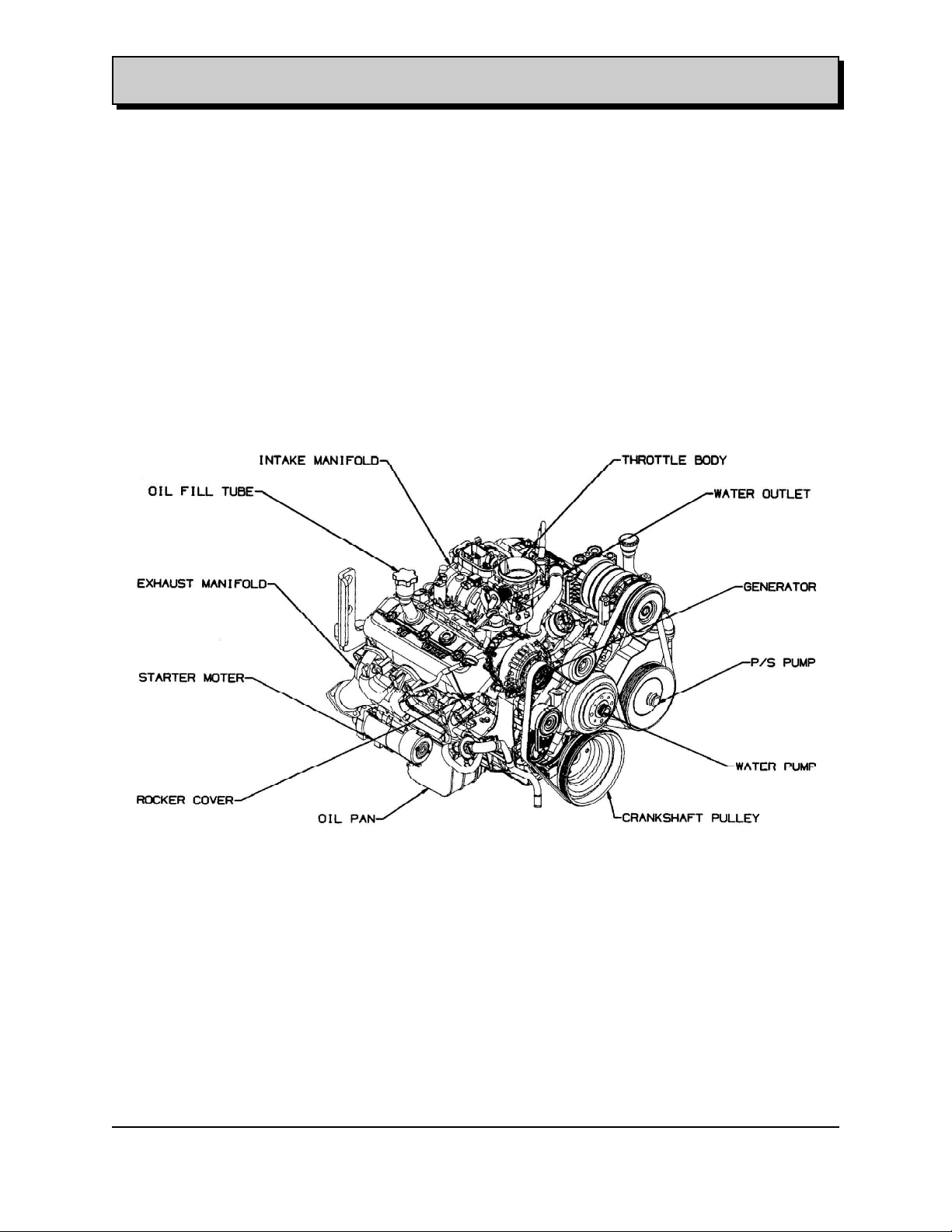
The figure 2.1-I shows the 4.3L V6 90 Degree Engine.
L35 Isometric View
Figure: 2.1-I
2 . 2 FEATURES
The model year 2001 for 4.3L V6 90 Degree Engine has one version: L35.
This Engine has specific values of power and torque, which allow for a very wide range of
application up to 15000 Lbs. GVW.
The more distinctive common features of this family of engines are:
-Optimized Intake Manifold
-Stiff Oil Sump
-High reliability and durability
-OBDII compliant
File: c:\data\manuales\v6-truck\am43v6#3.doc
Contact:Luis Nespolo - (248) 857-1558 Printed: 8/15/00
1
Page 4

ENGINE APPLICATION MANUAL GM Powertrain
Gasoline 4.3L V6 90 Degree Revised: 08/15/2000
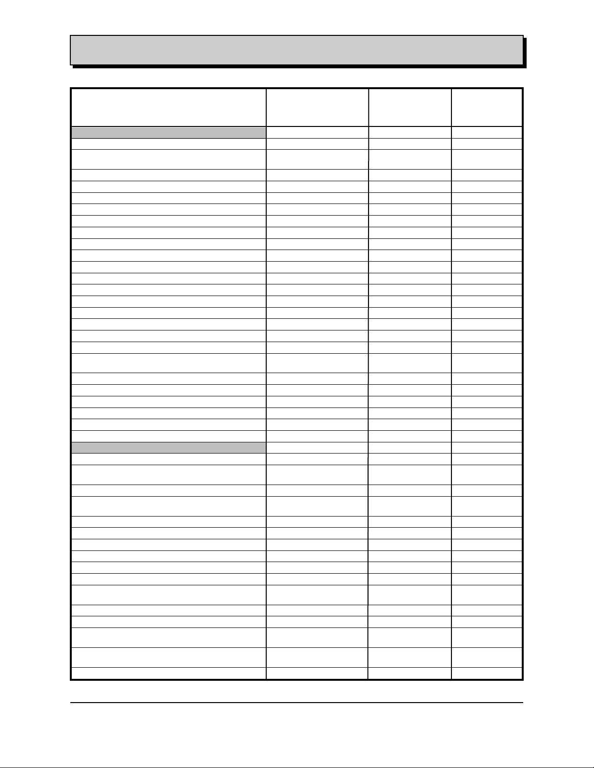
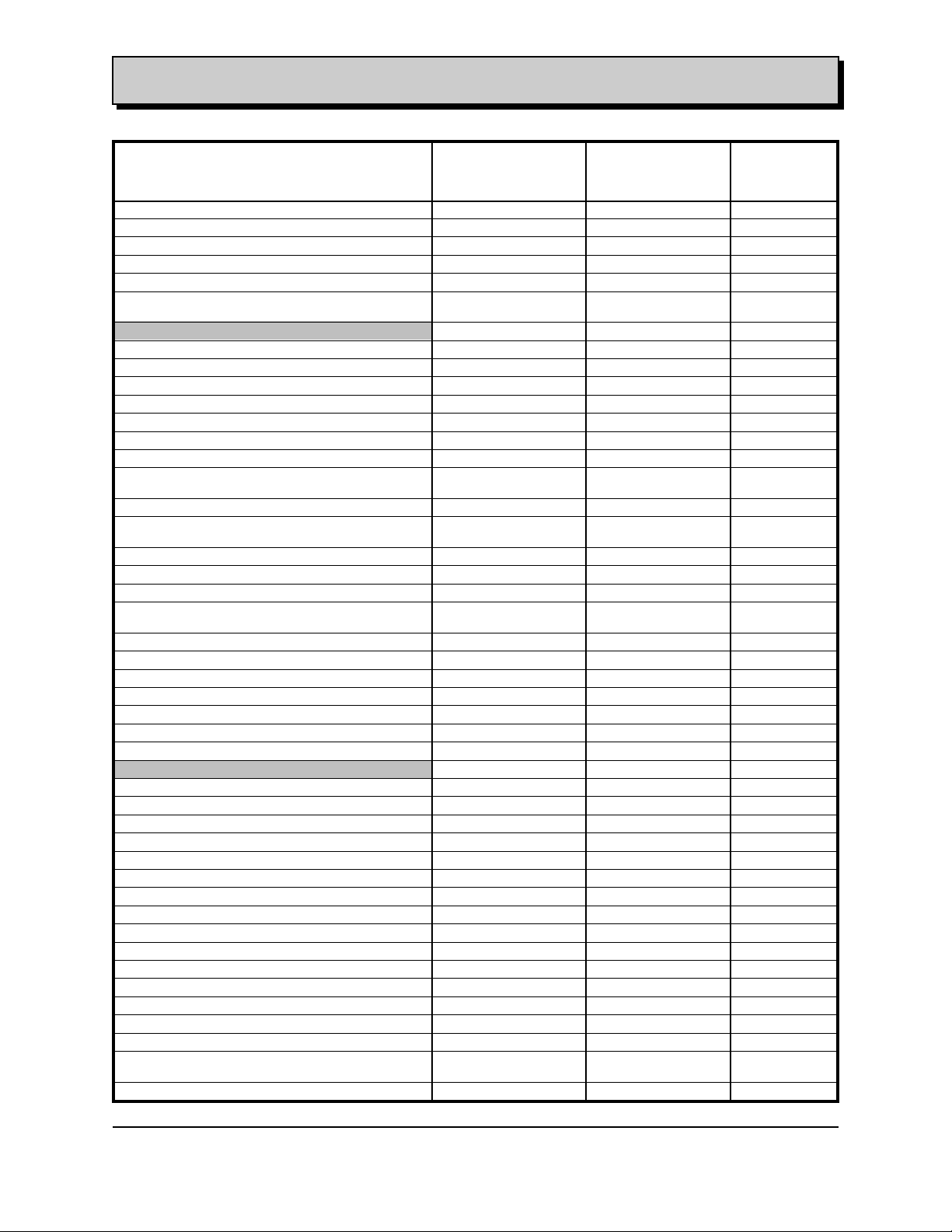
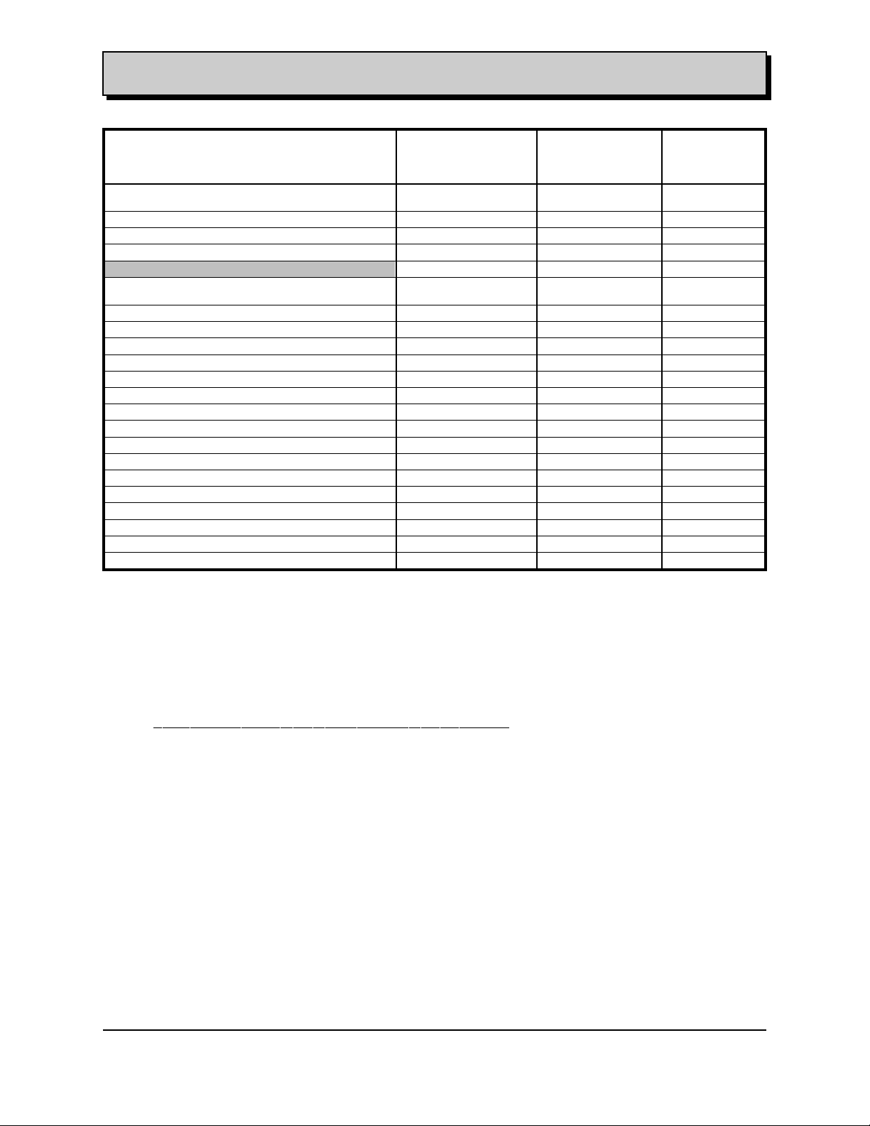
2 . 3 PRODUCT SPECIFICATION SUMMARY
2.3.1 SPECIFICATION
ENGINE L35 L35 UNITS
Truck Application Marine
Application
PERFORMANCE
Rated Power 200 223 hp
Rate Power Speed 4600 4800 rpm
Rated Torque 260 275 Lb. ft
Rated Torque Speed 2800 3800 rpm
Torque Extension Speed Range
(From Peak Torque to Peak Power) 1800 1000 rpm
Exhaust Restriction at Rated Power 8.85 to 8.58 0 in hg
(Better than) @ 4600 rpm Piezometer
Inlet Restriction at Rated Power w/Filter -0.89 0 in hg
Redline Speed 5000 5000 rpm
Fuel Cut-Off Speed, Nominal Conditions 5200 5200 rpm
Fuel Cut-Off Speed, Cold Conditions 5200 5200 rpm
Maximum Upshift Speed 5100 Man - 5200 Auto N/A rpm
Minimum Idle Speed 525 650 rpm
Minimum Unassisted Start Temperature -20 -20 Degree C
PHYSICAL/CONTENT
Type: 4 Cycle 4 Cycle
Service Type Naturally Aspirated Naturally Aspirated
Configuration: V V
Bank Angle: 90 90 Degree
Number of Cylinders: 6 6
Valvetrain Configuration: OHV OHV
Number of Valves per Cylinder: 2 2
Displacement: 4302 4302 cc.cm
Bore: 101.6 101.6 mm
Stroke: 88.4 88.4 mm
Compression Ratio: 9.4:1 9.4:1
Firing Order: 1-6-5-4-3-2 1-6-5-4-3-2
Rotational Direction: CW CW
Fuel Injection Pump Electronic Electronic
Certification Federal & California N/A
Engine Mass 200 200 Kg
Spark Plugs 41-932 (0.060”) 41-932 (0.060”)
Oil Filter PF-52 PF-52
Controller Electronic Electronic
SubSystems
Air Intake Subsystem
Throttle Body Type SCPI SCPI
Max Air Flow Rate: 158@ 4600 rpm 158@ 4600 rpm Gr/sec
Intake manifold : Symmetrical Runner Symmetrical Runner
Lower Intake: Aluminum Aluminum
Upper Intake: Composite Composite
@ 4600 rpm Piezometer
(-40) (-40)
Sequential Central Sequential Central
Port Injection Port Injection
File: c:\data\manuales\v6-truck\am43v6#3.doc
Contact:Luis Nespolo - (248) 857-1558 Printed: 8/15/00
2
Page 5
ENGINE APPLICATION MANUAL GM Powertrain
Gasoline 4.3L V6 90 Degree Revised: 08/15/2000
ENGINE L35 L35 UNITS
Truck Application Marine
Application
Cylinder Head Subsystem
Cylinder Head
Material Cast-Iron Cast-Iron
Cylinder Head Type: OHV OHV
Valves Actuation: Push Rod Push Rod
Rocker Arm Ratio 1.5:1 1.5:1
Valve Train
Valves per Cylinder: 2 2
Valves Angle from Vertical: 15 15 Degree
Lifters - Type Hydraulic Roller Hydraulic Roller
Valve Guides Cast Iron Cast Iron
Intake Valves
Material 1541 Steel 1541 Steel
Head Diameter 49.3 49.3 mm
Stem Diameter 7.965 7.965 mm
Length 123.68 123.68 mm
Seats 45 Degree 45 Degree
Lift 11.2 11.2 mm
Exhaust Valves
Material 21 - 4N 21 - 4N
3140 Welded Tip 3140 Welded Tip
Head Diameter 38.1 38.1 mm
Stem Diameter 7.965 7.965 mm
Length 124.84 124.84
Seats 45 Degree 45 Degree
Lift 11.0 11.0 mm
Main Block Subsystem
Block Assembly:
Material Cast-Iron Cast-Iron
Cylinders Cast Iron Cast Iron
Lower Structure Four main bearing Four main bearing
Bore Spacing 111.76 111.76 mm
Deck Height 234.7 234.7 mm
Connecting rods:
Material - Forged-SAE 1141 Forged-SAE 1141
Length - 154.9 154.9 mm
Bolts 9 9 mm
Bearings Aluminum Tin Aluminum Tin
Rod Length to Stroke Ratio 1.68:1 1.68:1
Piston
Type - Strutless Strutless Cam Turned
Material - Eutectic Cast Eutectic Cast
Weight 437 437 Gr
GM232-M GM232-M
Stainless Steel with Stainless Steel with
GM232-M GM232-M
Supports Supports
Silicon Alloy Silicon Alloy
Flat Top Flat Top
Aluminum Alloy Aluminum Alloy
File: c:\data\manuales\v6-truck\am43v6#3.doc
Contact:Luis Nespolo - (248) 857-1558 Printed: 8/15/00
3
Page 6

ENGINE APPLICATION MANUAL GM Powertrain
Gasoline 4.3L V6 90 Degree Revised: 08/15/2000
ENGINE L35 L35 UNITS
Truck Application Marine
Application
Piston Pins
Type - Fixed 24X70 Fixed 24X70 mm
Material - Steel SAE 1019 Steel SAE 1019
Piston Rings
Compression Rings Number: 2 2
Top Compression Steel Barrel Steel Barrel
Second Compression Cast Iron Cast Iron
Oil Control Rings Number - 1 1
Type - Low Tension Low Tension
Material - Plated Steel Plated Steel
Camshaft
Material - 5150 5150
Description Gun Drilled Gun Drilled
Base Circle Diameter: 39.4 39.4 Mm
Drive Chain Pitch Roller 3/8 3/8
Camshaft Valve Timing:
Intake Valve........Opens -33 -33 Crk Degree
Closes 286 286 Crk Degree
Exhaust Valve.....Opens -271 -271 Crk Degree
Closes 48 48 Crk Degree
Camshaft Bearings Steel Backed Steel Backed
Valve Springs
Material Super Clean Super Clean
Type Double Shot Double Shot
Dimension 4.6 mm 4.6 mm
Closed (Valve Closed) 356 356 Newtons
Open (Rate) 65 65 Newtons/mm
Crankshaft
Material - Cast Nodular Cast Nodular
Number of Counterweights 6 6
Main Journal Diameter - 62.2 62.2 Mm
Crank Pin Journal Diameter 57.1 57.1 Mm
Bearings Aluminum Tin Aluminum Tin
Torsional Damper Ring Inertia Ring Inertia Rubber Mounted
Crankcase Ventilation Negative Closed Negative Closed
1.5mm 1.5mm
1.5 mm 1.5 mm
3 Pieces 3 Pieces
Steel Billet Steel Billet
BTDC BTDC
ATDC ATDC
BTDC BTDC
TDC TDC
Copper/Lead Copper/Lead
Cr-Si Cr-Si
Peened Peened
Round Round
Undercut Rolled Fillet Undercut Rolled Fillet
Silicon Alloy Silicon Alloy
(Vacuum created from (Vacuum created from
Intake Manifold) Intake Manifold)
File: c:\data\manuales\v6-truck\am43v6#3.doc
Contact:Luis Nespolo - (248) 857-1558 Printed: 8/15/00
4
Page 7
ENGINE APPLICATION MANUAL GM Powertrain
Gasoline 4.3L V6 90 Degree Revised: 08/15/2000
ENGINE L35 L35 UNITS
Truck Application Marine
Application
Balance Shaft
Type First Order First Order
Material Nodular Cast Nodular Cast
Rotation CCW CCW
Speed Same as Crank. Same as Crank.
Drive Helical Gear 14 ° Helical Gear 14 °
Oil Lubrication
Main and Rod Bearings Pressure Pressure N/a
Camshaft Pressure Pressure N/a
Timing Gear Splash Splash N/a
Connecting Rods Pressure Pressure N/a
Valve Mechanism Pressure Pressure N/a
Cylinder Walls Splash Splash N/a
Piston & Pins Splash Splash N/a
Cylinder Head Hollow Hollow N/a
Oil Capacity
Oil 5W-30W 5W-30W N/a
W/ Filter 4.5 4.5 Qts
W/o Filter 4.0 4.0 Qts
Oil Filter
Type Full Flow Full Flow N/a
Capacity 0.3 0.3 Qts
Oil Pump
Type Spur Gear Spur Gear N/a
Normal Pressure 40-45 psi 40-45 psi @ 2000 RPM
Idle Pressure 20-25 psi 20-25 psi @ Idle
Oil Flow @ 1000 RPM 2 2 GPM
Drive Camshaft Camshaft N/a
Fuel Injection System
Mean Features
Injection Pump Make Delphi Delphi
Type Top Feed Top Feed
Model SCFI SCFI
Injection Timing Sequential Sequential
Operating Pressure 425 +/- 9 425 +/- 9 KPa
Opening Pressure 285 +/- 9 285 +/- 9 KPa
Fuel Pump
Fuel Pump Make Delphi Delphi
Type 44MM -G-Rotor 44MM –G-Rotor
Minimum Fuel Flow 25 25 Gram/Sec
Maximum Fuel Flow TBD TBD Gram/Sec
Fuel Pump Voltage Range 6-12 6-12 Volts
Fuel Pump Pressure 425 425 Kpa
Fuel Filter Delphi Delphi
Type Full Full
Material Nylon 66 Nylon 66
Off Cam Off Cam
Push Rod Push Rod
Mineral Mineral
PF-47 PF-47
Recirculation Recirculation
File: c:\data\manuales\v6-truck\am43v6#3.doc
Contact:Luis Nespolo - (248) 857-1558 Printed: 8/15/00
5
Page 8
ENGINE APPLICATION MANUAL GM Powertrain
Gasoline 4.3L V6 90 Degree Revised: 08/15/2000
ENGINE L35 L35 UNITS
Truck Application Marine
Application
Regulator Delphi Delphi
Nominal Pressure 425 425 Kpa
Injectors Delphi Delphi
Recommended Fuel 87 87 Octane = (R+M)/2
Water Pump Type: Centrifugal Centrifugal
Water Pump Maximum Flow @ Engine RPM: 76.5 76.5 GPM @ 4600
Maximum Sustained Coolant Temperature: 262 262 F
Thermostat Setting
Starts to Open 180 180 F
Full Open 262 262 F
Bearing Type Ball/Roller Ball/Roller
Impeller Material Cast iron Cast iron
Housing Material Cast iron Cast iron
By Pass Recirculation Type External External
Water Jackets full length of Cylinder Yes Yes
Water Jackets all around Cylinder Yes Yes
Water Jackets open at head face No No
Surge Tank System No No
Coolant Fill LocationDeaeration Tank Deaeration Tank
Circulation Thermostat Type Bypass Bypass
- direction of rotation : CCW CCW
- drive ratio (relative to crankshaft) 1.25 1.25
Cartridge Cartridge
RPM
2.3.2 Fuel Requirements
The 4.3L V6 90 Degree Engine System meets the emissions standard established in the FMVS
and EPA regulations with fuel quality in accordance with the API standards.
The engine must operate on the following types of fuels:
Unleaded Gasoline 87 (R+M)/2 (ASTM D4814),
Unleaded Gasoline 87 (R+M)/2 with up 15 % MTBE (Methyl Tertiary-Butyl Ether),
Canadian Gasoline 87 (R+M)/2 (CGSB 3.5-92) w/ MMT @ 18 mg/L manganese,
Reformulated Gasoline,
Premium Unleaded 91 (R+M)/2,
Export Gasoline as low as 80 (R+M)/2,
South American Gasoline with Peroxide contamination to 2.5%
Methanol mixes with gasoline to 15 %,
Ethanol mixes with gasoline to 25 %, Brazilian fuel system (SCPI) required.
Leaded Gasoline. Special cylinder heads required- NM8
File: c:\data\manuales\v6-truck\am43v6#3.doc
Contact:Luis Nespolo - (248) 857-1558 Printed: 8/15/00
6
Page 9
ENGINE APPLICATION MANUAL GM Powertrain
Gasoline 4.3L V6 90 Degree Revised: 08/15/2000
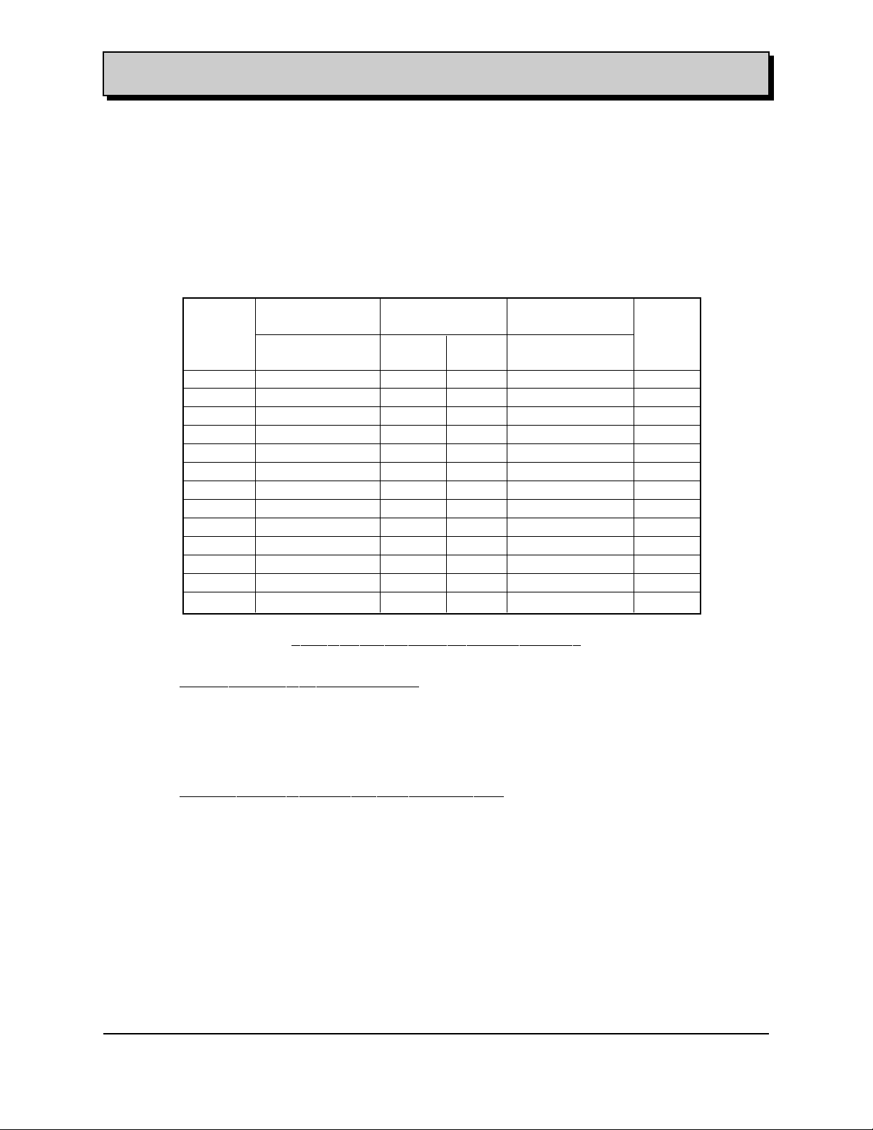
2. 3 . 2 Performance
2.3.2.1 Engine Power & Torque
The performance of the 4.3L V6 Engine is specified in the following paragraphs.
The Fig 2.3.2.1-I shows the following performance characteristics for the L35 engine: Power,
Torque and Speed Range.
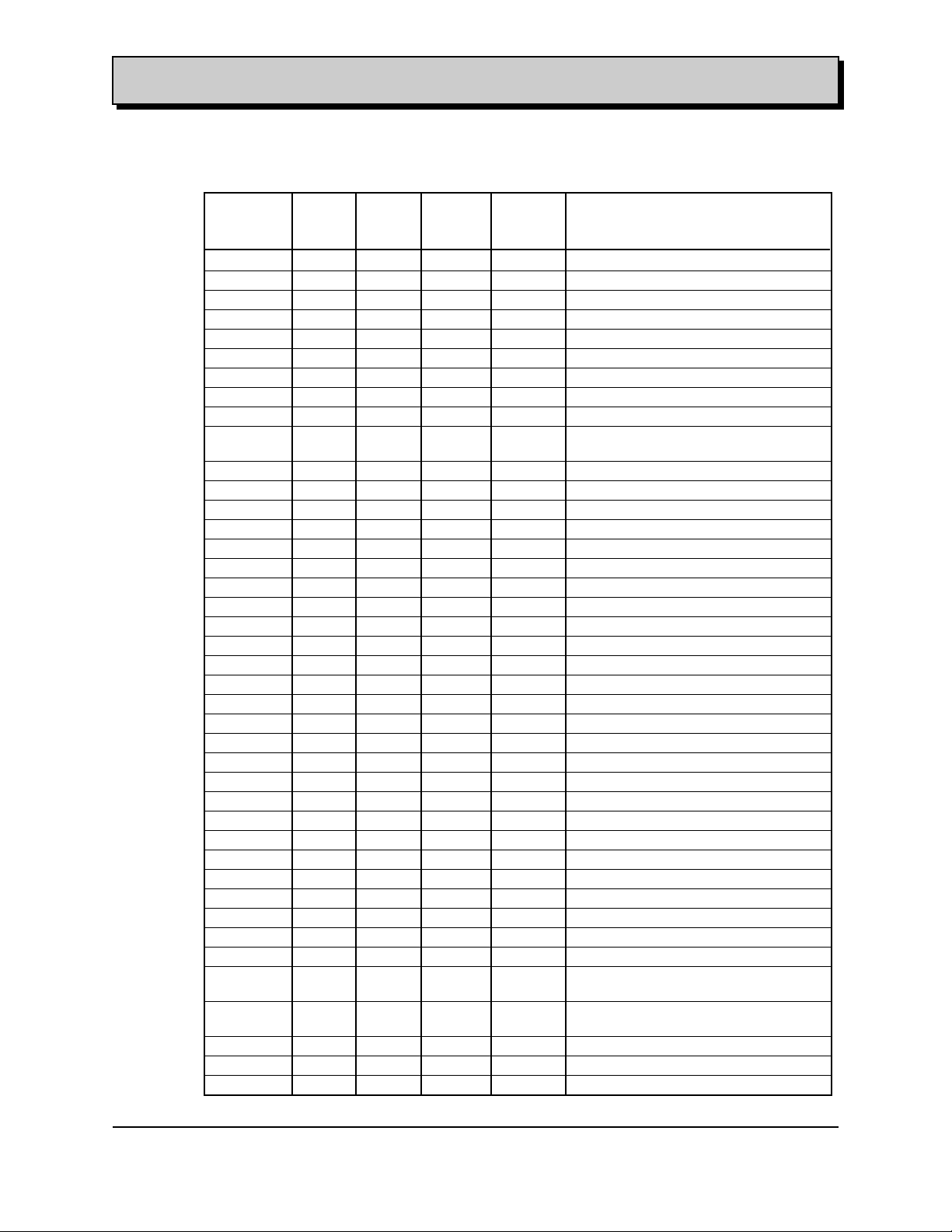
The engine will deliver the power and torque levels within +/-5% (after run in) as shown in
Table 2.3.2-I.
RPM Truck Marine Industrial Notes
Applications Applications Applications
Power Torque Power Torque Power Torque
HP Lbs.-ft HP Lbs.-ft HP Lbs.-ft
800 32.4 210.4 35.7 233.5 N/A N/A
1200 50.7 221.9 57.0 248.6 35 200
1600 72.6 238.1 78.7 257.7 60 210
2000 93.8 246.1 99.1 260.2 80 220
2400 116.3 254.3 120.3 262.5 105 230
2800 137.9 258.2 143.4 269.1 118 220
3200 157.5 257.9 166.4 272.7 120 210
3600 174.7 254.4 188.2 274.1 119 200
4000 188.5 247.1 206.2 270.2 118 190
4400 195.8 233.0 217.6 259.5 N/A N/A
4600 198.1 226 220.8 252.0 N/A N/A
4800 197.8 216.3 221.6 242.3 N/A N/A
5200 192.3 194.2 216.0 218.0 N/A N/A
Fig 2.3.2.1 -I 4.3L V6 Engine Power & Torque
Test Conditions for Truck Applications
* Based on the following conditions (measured at maximum rated speed W.O.T):
-Exhaust restriction 8.5” of Hg
-Air Intake temperature 77° F
-Intake restriction - 1” of Hg
-SAE J1349
Test Conditions for Marine & Industrial Applications
* Based on the following conditions (measured at maximum rated speed W.O.T):
-Exhaust restriction: 0 of Hg
- Air Intake temperature: 77 ° F
-Intake restriction - 1” of Hg
-GMPT Test #20
-This data reflects the Maximum values obtained with Different Intakes Manifolds & Fuel
Systems
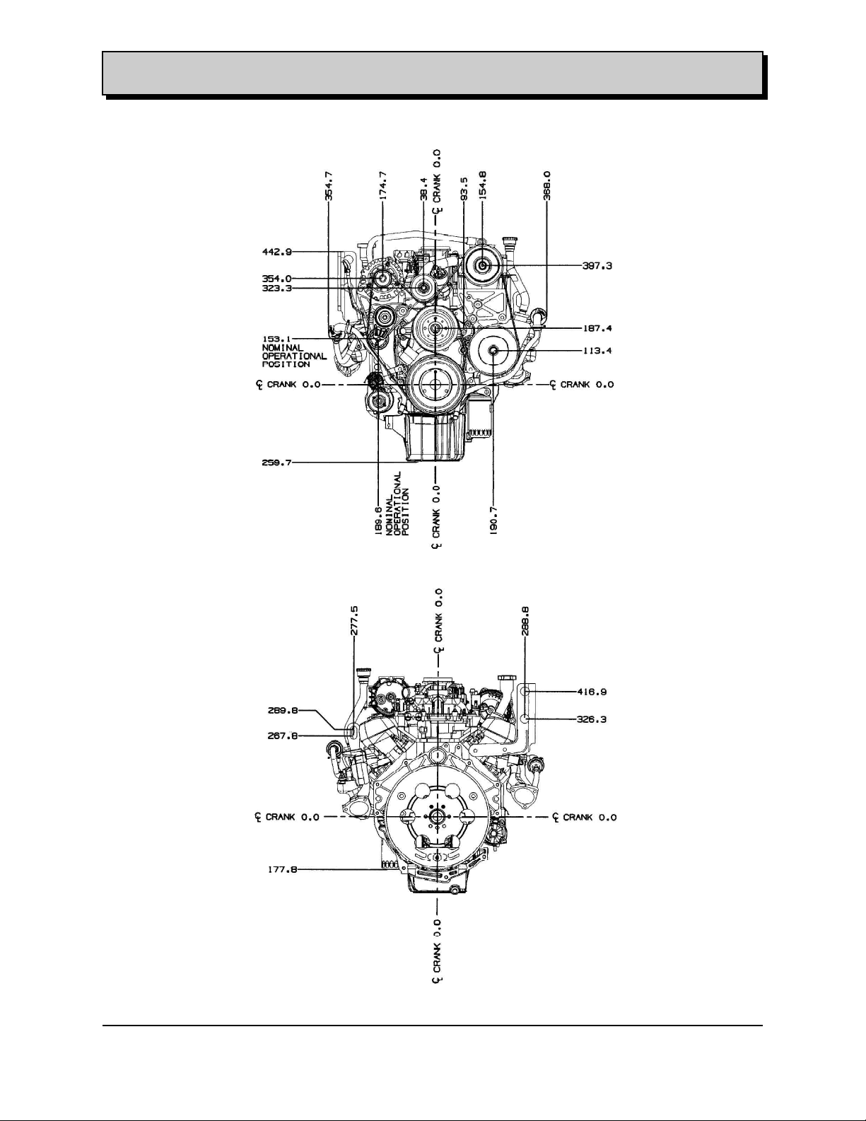
2 . 4 FEATURE LOCATION ILLUSTRATIONS
Front, Rear, Rh and Lh views of the 4.3L V6 90 Degree are included here with its overall dimensions
for preliminary packaging evaluations.
File: c:\data\manuales\v6-truck\am43v6#3.doc
Contact:Luis Nespolo - (248) 857-1558 Printed: 8/15/00
7
Page 10
ENGINE APPLICATION MANUAL GM Powertrain
Gasoline 4.3L V6 90 Degree Revised: 08/15/2000
L35 Main Views
L35 Front View
L35 Rear View
File: c:\data\manuales\v6-truck\am43v6#3.doc
Contact:Luis Nespolo - (248) 857-1558 Printed: 8/15/00
8
Page 11
ENGINE APPLICATION MANUAL GM Powertrain
Gasoline 4.3L V6 90 Degree Revised: 08/15/2000
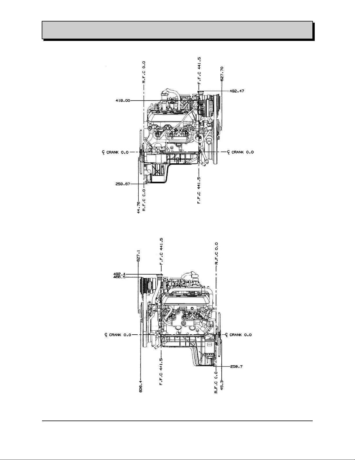
L35 RH Side View
L35 LH Side View
File: c:\data\manuales\v6-truck\am43v6#3.doc
Contact:Luis Nespolo - (248) 857-1558 Printed: 8/15/00
9
Page 12

ENGINE APPLICATION MANUAL GM Powertrain
Gasoline 4.3L V6 90 Degree Revised: 08/15/2000
2 . 5 CONFIGURATION AS SHIPPED
2. 5 . 1 Engine as Shipped
Engine as shipped from the engine plant is to conform to a common state of dress as described
below. The following components are installed at the engine plant:
Harmonic balancer Crankshaft sensor
Direct drive accessories (not belt driven) E.G.R. system
Engine lift brackets Engine oil
Engine oil dipstick and tube Exhaust manifold(s)
Exhaust manifold heat shields (As required) Engine Fuel system
Heater hose nipples Coolant temperature sensor/switch
Manifold air pressure sensor Oil pressure sensor/switch
Oil filter (except remote mounted) Transmission alignment dowels
Water pump Flywheel and or Flexplate
Crankcase ventilation system
2 . 6 IDENTIFICATION AND MARKING
2.6.1 VIN Identification Labeling
There are two places for the stamping of the V.I.N.: one is provided side by side on the left hand
side of powertrain and the other is in rear face of cylinder case.
2.6.2 Emissions Certification Labeling
A vehicle emission control label that meets the format and content requirements of Federal
Regulation 40 CRF 86.095-35 and CARB Regulation Title XIII California Code of Regulations
Section 1965 shall be attached to the vehicle subsystem in the location required by the
regulations above.
Incomplete Vehicles manufactured in two or more stages shall meet the certification labeling
requirements of the regulations above.
Emissions Certification is not provided for Marine Industrial Applications.
2.6.3 Engine Identification - Broadcast Codes
The 4.3L V6 Engine has an identification number cast into the cylinder case front LH side.
Also, an Engine Verification Label is applied to the rear of the left bank cylinder head. This is the
single label location for passenger car engines. In addition to the LH rear head location, the
truck engines have another identical label applied to the oil pan (near the bottom of the engine)
on the right side.
The labels show the following information:
• First Two characters: 10 - Indicates an engine not a transmission.
• Next 3 characters: Broadcast code (engine configuration which includes a cross reference to
model year of build):
- Model year (1st letter)
characters: Julien Date of Build
• Last 4 Characters: Sequence number of build on that date.
Translated the engine verification number shown in the sample label below identifies an engine,
broadcast code (XJB) (1999 5.3L Federal Auto), built at Romulus on February 10 , 1999;
sequence number 1034.
Example: * 10XJB W990411034*
File: c:\data\manuales\v6-truck\am43v6#3.doc
Contact:Luis Nespolo - (248) 857-1558 Printed: 8/15/00
10
Page 13

ENGINE APPLICATION MANUAL GM Powertrain
Gasoline 4.3L V6 90 Degree Revised: 08/15/2000
2.6.3.1 Engine Option Description
RPO Description Notes
L35 4.3L V-6 Engine w/ SCPI
M30/MT1 Automatic Transmission
M50/MG5 Manual Transmission
K18 Air Injection (Electric pump)
KC4 Engine Oil Cooler
KL5 Gaseous Fuel Compatible
NA1 Below 8500# GVW
NA3 Emission System - Japan
NA4 Above 8500# GVW
NB6 Emission System - Calif. Tier 1 (-K18 on CK Manuals)
NC1 Emission System - Calif. LEV (+K18 on CK / -K18 on M/L)
NC8 Emission System - Calif. ULEV (-K18 on ML)
NF2 Emission System - Federal Tier 1 (-K18 on CK & P)
NF4 Emission System - Clean Fuel Fleet
NF7 Emission System - Federal N LEV
NM2 Emission System - Leaded Fuel (Export for ML & P)
NM8 Leaded Fuel System Compatible (Export for ST)
NN8 Emission Override - Unleaded Fuel (Export)
NW7 Traction Control
RHD Right Hand Drive
S5I Brazil Equipment
W99 Venezuela Equipment
TZ0 Mexican Equipment (Manual Transmission)
ZK3 G-Van Pull Ahead (Vehicle only)
File: c:\data\manuales\v6-truck\am43v6#3.doc
Contact:Luis Nespolo - (248) 857-1558 Printed: 8/15/00
11
Page 14
ENGINE APPLICATION MANUAL GM Powertrain
Gasoline 4.3L V6 90 Degree Revised: 08/15/2000
2.6.3.2 Engine Broadcast Codes & Part Numbers
Part TON ROM Broad Vehicle Description
Number Cast
Code
12559672 X AAA CK L35+M30+NF2 (-K18)
12559676 X AAF CK L35+M30+NC1 (+K18)
12559673 X AAB CK L35+MG5+NF2 (-K18)
12559677 X AAH CK L35+MG5+NC1 (+K18)
12559680 X ABA G-LD L35+M30+NA1-K18
12559681 X ABB G-HD L35+MT1+NA4 (-K18)
12559682 X ABC G-LD L35+M30+NA1+NF4+K18
12559684 X ACA ML L35+M30+NA3/NC1/NC8/NF2/NF4/
NF7
12559685 X ACB ML L35+M30+NM2
12559687 X ADA P L35+MT1+NF2-KL5
12559688 X ADB P L35+MT1+KL5+NF2
12559691 X X AFC S L35+M30-K18-NM8 (+NN8)
12559707 X AFL S L35+M30+NM8
12559692 X X AFD S L35+M50-K18-NM8 (+NN8)
12559708 X AFN S L35+M50+NM8
12559701 X X AFJ S L35+M30+K18+NF4
12559702 X X AFK S L35+M50+K18+NF4
12559695 X X AHC T L35+M50-K18-NM8-RHD
12559696 X X AHD T L35+M30-K18-NM8-RHD
12559709 X AHP T L35+M50+NM8-W99
12559710 X AHS T L35+M50+W99+NN8
12560378 X AHX T L35+M30+RHD-NM8-K18
12560379 X AHY T L35+M50+RHD-NM8-K18
12559711 X AHT T L35+M30+NM8
12559705 X X AHL T L35+M30+NF4+K18
12559706 X X AHN T L35+M50+NF4+K18
12560483 X 1LB —- Marine (Volvo) 2Bbl w/Dist.
12560485 X 1LJ —- Marine (Merc) 2Bbl w/o Dist.
12560484 X 1LC —- Marine 4Bbl w/ Dist.
12560486 X 1LK —- Marine 4Bbl w/o Dist.
12560481 X 1LT —- Indust 2Bbl Gaseous - Bucks
Irrigation
12560482 X 1LX —- Indust 2Bbl Gas - Williams
Powertrain
12559712 X 1LA T L35+M50+S5I (Brazil)
12559713 X 1LD T L35+M30+S5I (Brazil)
File: c:\data\manuales\v6-truck\am43v6#3.doc
Contact:Luis Nespolo - (248) 857-1558 Printed: 8/15/00
12
Page 15
ENGINE APPLICATION MANUAL GM Powertrain
Gasoline 4.3L V6 90 Degree Revised: 08/15/2000
3.0 GMPT SYSTEM INTERFACES
3.1 INTERNAL INTERFACES TO GMPT
3.1.1 Engine Interface to transmission
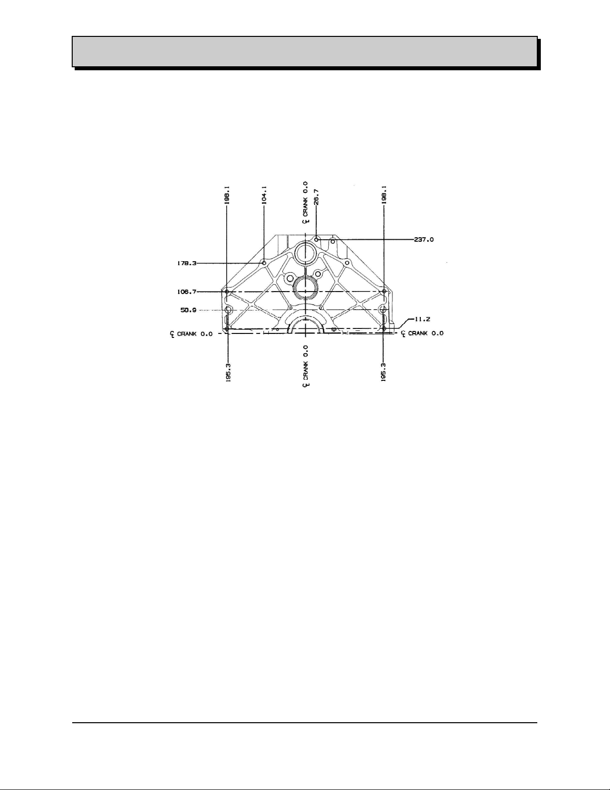
The transmission shall be attached to the rear end of the engine, which provided the flange face
attachment illustrated in the figure 3.1.1- I.
Figure 3.1.1-I: Transmission attachment
3.1.1.1 Automatic Transmission
The 4.3L V6 engine could be mated to either: the GM Automatic Transmission Hydra Matic
4L60E or the GM Automatic Transmission Hydra Matic 4L80E
Figure 3.2.1-I to 3.2.1-XVIII shows the PCM Engine to Automatic Transmission Mechanization
Diagram.
3.1.1.2 Manual Transmission and Clutch
The GM Manual Transmission recommended is a Five Speed Manual (MW 3)
The following engine-transmission, clutch interface issues must be considered:
Manual transmissions require the engine crankshaft pilot bearing to be able to support up to 920
lbs (4292 N) of radial load due to transmission internal gear forces.
File: c:\data\manuales\v6-truck\am43v6#3.doc
Contact:Luis Nespolo - (248) 857-1558 Printed: 8/15/00
13
Page 16
ENGINE APPLICATION MANUAL GM Powertrain
Gasoline 4.3L V6 90 Degree Revised: 08/15/2000
The following table shows the different Transmissions and Components coupled to the L35 engine and
GM platforms.
Transmission P-Truck C/K Truck G-Van M/L -Van S/T Truck
( UPC: 7 )
Auto 4L80E MT1 24210752 N/A 24210754 N/A N/A
Bolt/Screw/Stud 15724226 N/A 15724226
11514224 11514224 N/A N/A
Auto 4L60E M30 N/A 24211665 24211668 24211663 24211662
24211666 24211664 24211663
24211667
Brace N/A N/A N/A 15992466 N/A
Bolt/Screw/Stud N/A 11515768 11515768 15724226 11517000
15724226 15724226 11517000 1261968
25624806
Manual 5-Speed MW3 15020892 N/A N/A N/A N/A
15031131
Bolt/Screw/Stud 11514224 N/A N/A N/A N/A
Manual 5-Speed MG5 N/A 15769087 N/A N/A N/A
15769088
Bolt/Screw/Stud N/A 11515768 N/A N/A N/A
Manual 5-Speed MW2 N/A N/A N/A N/A 15045050
Bolt/Screw/Stud N/A N/A N/A N/A 11515768
Manual 5-Speed M50 N/A N/A N/A N/A 15769696
15769697
15769698
Bolt/Screw/Stud 11517000
File: c:\data\manuales\v6-truck\am43v6#3.doc
Contact:Luis Nespolo - (248) 857-1558 Printed: 8/15/00
14
Page 17

ENGINE APPLICATION MANUAL GM Powertrain
Gasoline 4.3L V6 90 Degree Revised: 08/15/2000
3.1.2 Engine Interface to PCM ( Vehicular and Marine/Industrial Application)
The 4.3L V6 90 Degree Engine uses the Powertrain Control Unit (PCM) to control the engine,
automatic transmission, the vehicle performance parameters and the onboard diagnostic system.
3.1.2.1 Inputs from the Engine to the PCM
The following Inputs are internal engine parameters and must be supplied to the Powertrain
Control Module:
Barometric Pressure (Or Manifold Absolute Pressure) - POA Engine Assembly
Mass Airflow Sensor (Air Cleaner/Air Duct)
Engine Speed
Crankshaft Sensor and Camshaft Sensor
Knock Sensor
Air intake Temperature Sensor (POA MAF) - (Only for the GMT-800 Truck)
Engine Coolant Temperature ECT Sensor-POA Engine Assembly
Engine Oil Pressure Sensor
3.1.2.2 Outputs from PCM to the Engine
Fuel Injectors Management – (Injection Pulse Width Signal)
Idle Air Control Motor (IACV)
Ignition Control Coil Module
Linear EGR Valve Solenoid
Evap. System
Purge Solenoid
Secondary Air (AIR) System
A/C Control
Serial Data
3.1.3 PCM Interface to Transmission
The PCM uses an Electronic Transmission Control Algorithm to monitor and control the transmission.
This algorithm is actually a combination of four algorithms, these algorithms monitor and control
the various aspects of the transmission shifting.
3.1.3.1 Input Algorithm:
The Input Algorithm samples all external sensors and scale these values.
3.1.3.2 Shift Control Algorithm:
The Shift Control Algorithm determines which gear ratio the transmission is currently in and
changes the state of the control solenoid to accomplish a shift.
The shift pattern is controlled by a set of tables. These contain the vehicle speed at which the
shift is to occur as a function of throttle position.
In the manual mode, the current gear may be determined by the operator’s movement of the
gearshift selector lever.
3.1.3.3 Shift Quality Algorithm:
The Shift Quality Algorithm determines shift quality (or firmness).
This is accomplished by controlling the pressure control solenoid, which regulates the torque
signal modulation pressure.
This pressure is determined by a table that is based on vehicle speed and Throttle position.
Garage Shift quality (shifting from Park or Neutral to Drive or Reverse when the vehicle is
stationary) is also controlled by torque signal pressure.
File: c:\data\manuales\v6-truck\am43v6#3.doc
Contact:Luis Nespolo - (248) 857-1558 Printed: 8/15/00
15
Page 18

ENGINE APPLICATION MANUAL GM Powertrain
Gasoline 4.3L V6 90 Degree Revised: 08/15/2000
3.1.3.4 TCC Control Algorithm
The TCC algorithm determines when the torque converter clutch is applied or released, using
a set of tables. These tables also determine and control the rate of application and release of
the TCC based on Throttle position
3.1.3.5 Inputs from Transmission to PCM
The following are external Inputs coming from the Transmission to the PCM:
Transmission Speed Sensor
Transmission Fluid Temperature Sensor
Transmission Range Pressure Sensor
3.1.3.6 Output to the Transmission from PCM
TCC Solenoid
Transmission Shift solenoids
Pressure Control Solenoid
3.1.4 PCM Interface to Vehicle
3.1.4.1 External Inputs of the Engine
The following are external Inputs coming from the vehicle to the PCM:
A/C Status
Ignition Voltage
Serial Data (Diagnostics)
Brake/ Clutch Status
4WD Lo Switch (If Applicable)
Diagnostic Enable
Cruise Control Inputs
Tow/Haul Input Switch
3.1.4.2 Output to the Vehicle:
Data link Connector
MIL “Service Engine Soon” Lamp
“Service Throttle Soon” (STS) Lamp
File: c:\data\manuales\v6-truck\am43v6#3.doc
Contact:Luis Nespolo - (248) 857-1558 Printed: 8/15/00
16
Page 19
ENGINE APPLICATION MANUAL GM Powertrain
Gasoline 4.3L V6 90 Degree Revised: 08/15/2000
3.1.5a PCM Pin Out and Pin In – Truck Applications
See Figure 3.1.5 - I Powertrain Control Module Diagram to reference the following pin out and
pin in connector information
Figure : 3.1.5a - I PCM Pin Out /In Connector C1
File: c:\data\manuales\v6-truck\am43v6#3.doc
Contact:Luis Nespolo - (248) 857-1558 Printed: 8/15/00
17
Page 20
ENGINE APPLICATION MANUAL GM Powertrain
Gasoline 4.3L V6 90 Degree Revised: 08/15/2000
Figure : 3.1.5a -II PCM Pin Out /In Connector C2
File: c:\data\manuales\v6-truck\am43v6#3.doc
Contact:Luis Nespolo - (248) 857-1558 Printed: 8/15/00
18
Page 21
ENGINE APPLICATION MANUAL GM Powertrain
Gasoline 4.3L V6 90 Degree Revised: 08/15/2000
The following table shows the different PCM ASM and Components coupled to the L35 engine per GM
platforms.
PCM
( 12 F ) P-Truck C/K Truck G-Van M/L -Van S/T Truck
Module ASM 9368071 12201281 12201281 12201281 12201281
52370668
Housing Extension 15003789
Bracket 15005865 15047570 15766026 15047570 15767011
15714426
Bolt/Screw/Nut 3846202 11516568 11514519 11516568 11516568
11514139 11514006
Sensors P-Truck C/K Truck G-Van M/L -Van S/T Truck
( 12 F )
Oxygen Sensor 25312191 25312191 25312191 25312191 25312191
25312201 25314006 25314006 25314006 25314006
Mass Air Flow Sensor 25168491 Include in Air Include in Air Include in Air Include in Air
SubSystem SubSystem SubSystem SubSystem
File: c:\data\manuales\v6-truck\am43v6#3.doc
Contact:Luis Nespolo - (248) 857-1558 Printed: 8/15/00
19
Page 22

ENGINE APPLICATION MANUAL GM Powertrain
Gasoline 4.3L V6 90 Degree Revised: 08/15/2000
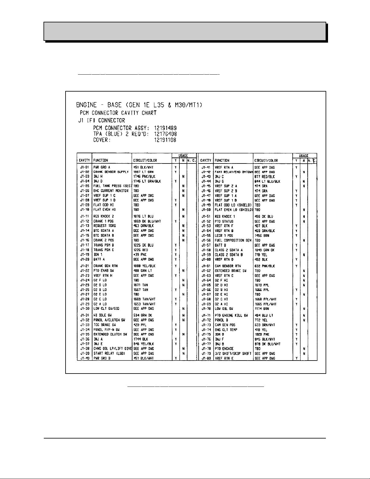
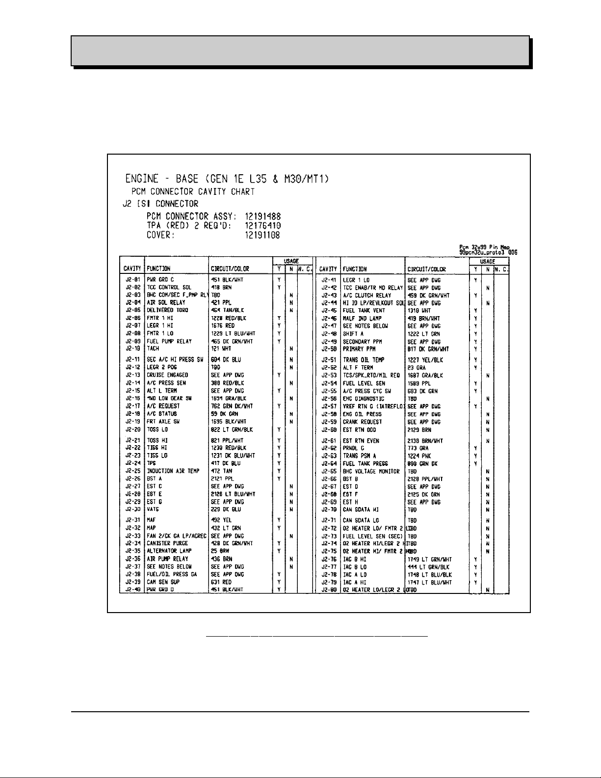
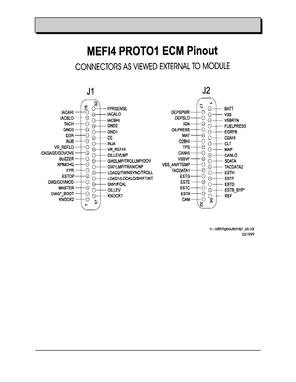
3.1.5b PCM Pin Out and Pin In – Marine and Industrial Applications
Marine Applications use a different control module : MEFI – 4 Multiport Electronic Fuel Injection.
Interfaces as those described for vehicles application, OBD II, and Emissions requirement are
not longer needed.
Table A.1 shows the connector pin out for MEFI Electronic Control Module (ECM) Part Number
12569494 Rev B.
Table A.1 – Pinout
PIN MEFI4 PIN NAME PIN MEFI4 PIN NAME
J1-1 KNOCK2 J2-1 BATT
J1-2 DIAG*_BOOT J2-2 V5B
J1-3 MASTER J2-3 V5BRTN
J1-4 GW2/GOVMOD J2-4 FUELPRESS
J1-5 ESTOP J2-5 EGRFB
J1-6 FPR J2-6 O2AHI
J1-7 RPMCHG J2-7 CLT
J1-8 BUZZER J2-8 MAP
J1-9 CKGAGE/GOVOVS J2-9 CANLO
J1-10 VR_REFLO J2-10 SDATA
J1-11 INJB J2-11 TACDATA2
J1-12 EGR J2-12 ESTH
J1-13 GND3 J2-13 ESTF
J1-14 TACH J2-14 ESTD
J1-15 IACBLO J2-15 ESTB_BYP*
J1-16 IACAHI J2-16 REF
J1-17 KNOCK1 J2-17 DEPSPWR
J1-18 OILLEV J2-18 DEPSLO
J1-19 GW1/FCAL J2-19 IGN
J1-20 LOAD1/LOCKLO/SHIFTINT J2-20 OILPRESS
J1-21 LOAD2/TWINSYNC/TROLL J2-21 MAT
J1-22 GW1LMP/TRAN/CNP J2-22 O2BHI
J1-23 GW2LMP/TROLLMP/GOV J2-23 TPS
J1-24 OILLEVLMP J2-24 CANHI
J1-25 VR_REFHI J2-25 VSSVF
J1-26 INJA J2-26 VSS_AN/FTEMP
J1-27 CE J2-27 TACDATA1
J1-28 GND1 J2-28 ESTG
J1-29 GND2 J2-29 ESTE
J1-30 IACBHI J2-30 ESTC
J1-31 IACALO J2-31 ESTA
J1-32 FPRSENSE J2-32 CAM
File: c:\data\manuales\v6-truck\am43v6#3.doc
Contact:Luis Nespolo - (248) 857-1558 Printed: 8/15/00
20
Page 23
ENGINE APPLICATION MANUAL GM Powertrain
Gasoline 4.3L V6 90 Degree Revised: 08/15/2000
File: c:\data\manuales\v6-truck\am43v6#3.doc
Contact:Luis Nespolo - (248) 857-1558 Printed: 8/15/00
21
Page 24

ENGINE APPLICATION MANUAL GM Powertrain
Gasoline 4.3L V6 90 Degree Revised: 08/15/2000
3.1.6 Engine interface to exhaust
3.1.6.1 Content
The engine is provided with exhaust manifolds for vehicles and Industrial Applications.
The exhaust manifold system includes the manifold, fasteners to the cylinder head, and
partial or full cover type heat shield. The exhaust manifold may also incorporate provisions
for EGR attachment.
Vehicle Exhaust System
The 4.3L V6 90 Degree Engine shall be attached to the vehicle and interface with the
Vehicle Exhaust System.
The Vehicle Exhaust System will be designed or adapted considering the following Issues:
Vehicle Exhaust System Back pressure: All performance parameters specified in paragraph:
2.3.2.1 were measured with a maximum exhaust restriction of 8.5” of Hg.
Thermal Management of Exhaust
Thermal management of exhaust
The following issues must be considered:
a. Location of Catalytic Converter: The location of the catalytic converter is determined by
resolving three competing needs. The first need is to locate the converter such that it is
close enough to the engine so that sufficient heat is transferred to the converter via the
exhaust stream so as to initiate catalytic activity and therefore constituent conversion
soon enough to meet emission requirements. The second need is to locate the catalytic
converter far enough downstream from the engine in the vehicle’s exhaust system so that
the converter will not be damaged during extended duration high exhaust gas stream
temperature excursions resulting from high speed and load operation of the engine. The
third need is to locate the converter in a position in the chassis where it will package with
sufficient clearance to surrounding components or systems to prevent heat related
failures in those systems or components.
b. Location of Oxygen Sensor(s)
All OBD II compliant exhaust systems contain enough oxygen sensors to guarantee
proper monitoring of the exhaust gases. Each engine cylinder bank requires an oxygen
sensor for air/fuel ratio control. An oxygen sensor is required behind each catalytic
converter for diagnosis purposes. Post converter oxygen sensors are also implied for
slow air/fuel ratio trim. Oxygen sensor wiring connections must be located to as to avoid
moisture contamination.
c. Converter Volume and Flow
d. Location of muffler
e Vibration/shock of catalytic converter
f. Material life for exhaust system through catalytic converter
g. Thermal Characteristics
h. Exhaust Leakage
The exhaust system must be leak free for the emission useful life of the vehicle.
In order to have a working definition of leak free, the exhaust system is divided into three
zones:
Zone A (A/F Control) Cylinder head / exhaust manifold interface to
control oxygen sensor
Zone B (Converter Feedstream) Control oxygen sensor to converter
Zone C (Diagnostic Feedstream) Converter to 12 inches downstream of the
diagnostic oxygen sensor
Maximum allowable leakage in each zone is 2 liters/minute at 15 kPa.
File: c:\data\manuales\v6-truck\am43v6#3.doc
Contact:Luis Nespolo - (248) 857-1558 Printed: 8/15/00
22
Page 25

ENGINE APPLICATION MANUAL GM Powertrain
Gasoline 4.3L V6 90 Degree Revised: 08/15/2000
The following table shows the different Exhaust Assemblies and Components coupled to the L35 engine
per GM platforms.
Exhaust P-Truck C/K Truck G-Van M/L -Van S/T Truck
( 8 C )
Manifold ASM 15986438 15029769 15029769 15029769 15029769
Pipe ASM Exhaust 15045399 15749444 15744824
15034810 15744826
15743099 15744828/9
Manifold Seal 12555091 15035747 11514597 12555091 12555091
15035748
Manifold Gasket 15997189 15997189 15997189 15997189 15997189
15767098
Shield 15753676 15027911 15027911 15736668
Screw/Bolt/Nut 11514597 15733192 15997953 15023752 15023752
15733192 15032594 11514597 11514597
Converter ASM 25160620 15052911 15159709 15744810 15744810
15986441 15756278 15160977 15749445 15749445
15700838 12568312
15747730
Converter Pipe ASM 15986425 15709444 15709444 N/A N/A
15986425
15986428
Converter Gasket 15027074 15027074 15027074 15027074 15027074
Shield 15739194 TBD 15739194 15027095 TBD
1507912 1507912 15150934
Clamp 15529483 15529483 15529483 15529483 15529483
Screw/Bolt/Nut 15709703 15709703 15709703 15709703 15709703
9442939 15997953 15997953 15997953 15997953
11517501 11517501 11517501 11517501
Muffler ASM 15727690 15040396 15008799 15756876 15756876
15040397 15159716 15756877 15756877
15061814 15761545
Exhaust Pipe ASM 15727691 15756780 15739879 N/A 15156883/4
15156936/5
Shield 15739195 15739195 15990607 15990607
Hanger/Bracket 15986421 15986421 15986421 15152715 15023065/6
15986422 15986422 15986422 15976360
15976332
Clamp 15595047 15595047 15595047 15595047 15595047
15529483 15529483 15529483 15529483 15529483
Screw/Bolt/Nut 11515799 11515799 11515799 11500831 11500831
11515216 11515216 11515216 11515768 11515768
9424320 9424320 9424320 15695050
File: c:\data\manuales\v6-truck\am43v6#3.doc
Contact:Luis Nespolo - (248) 857-1558 Printed: 8/15/00
23
Page 26
ENGINE APPLICATION MANUAL GM Powertrain
Gasoline 4.3L V6 90 Degree Revised: 08/15/2000
3.1.6.2 Back Pressure
Exhaust back pressure shall not exceed 8.5 inches of Hg at rated speed and load. Lower
exhaust back pressure is desired from a performance and fuel economy standpoint.
3.1.6.3 Packaging
The vehicle assembly plant attaches the exhaust pipe to the manifold with the proper
fasteners and a gasket or seal. Exhaust manifold takedowns will be 2 or 3 fastener designs.
Consult GM application engineer.
The current exhaust manifolds are made from Nodular Iron with incorporated and
detachable heat shields.
Fasteners at the manifold takedown must be capable of withstanding temperatures up to
800°C and will require stainless steel or sermagard coated steel. The gasket/seal must also
withstand these temperatures and will require stainless steel or stainless steel with mica or
grafoil.
The heat shield provided on the exhaust manifold will reduce radiant heat to nearby critical
components and reduce or minimize the number of separate shields required by the vehicle.
3.1.6.4 Exhaust Gas Recirculation (EGR)
EGR P-Truck C/K Truck G-Van M/L -Van S/T Truck
( 6 L 3 )
EGR ASM Valve 17200268 17200268 17200268 17200268 17200268
3.1.6.5 Secondary Air
GMPT will indicate the needs for secondary air recirculation.
The following table shows the different Secondary Air and EGR Assemblies and
Components coupled to the L35 engine per GM platforms.
Engine Secondary Air P-Truck C/K Truck G-Van M/L -Van S/T Truck
( 6T )
Pump Air Inj ASM 15059238 15053709 15056764
Hose ASM 15022544 N/A 15023825
Hose ASM By Pass 15022570 N/A 15760279
Stud 20513798 N/A
Washer 15953691
Strap 11509086
Bolt Screw 11508706
Pipe ASM 12561825 12562572 12561250/51
Check Valve (or Bypass) 12567731 12567745 15037955
Check Valve (or Bypass) 12567732 12567746 15056713
Bolt Screw 12558020 11515210 15695050
9440034
Gasket 12561871 12561871 12561871
Shield 15026631
Nut 11514596
File: c:\data\manuales\v6-truck\am43v6#3.doc
Contact:Luis Nespolo - (248) 857-1558 Printed: 8/15/00
24
Page 27

ENGINE APPLICATION MANUAL GM Powertrain
Gasoline 4.3L V6 90 Degree Revised: 08/15/2000
3.1.7 Engine Interface to Cruise Control
Figure 3.2.1-I to 3.2.1-XVIII shows the PCM Engine to Vehicle Mechanization Diagram with this
interface. The following table shows the different Cruise Control Modules and Components used
with the L35 engine and GM platforms.
Cruise Control P-Truck C/K Truck G-Van M/L -Van S/T Truck
( 6 N 4 )
Cruise Control Module 25315559 25315559 25315090 25315087 15028014
Cable 15040802 15040802 15031096 15045430 15045460
15040801 15040801 15751730
Bolt/Screw 11517009 11517009 15685170 11515928 11508010
11518009 11518009 15983425 11517507
15685170 15685170
3.1.8 Accelerator Pedal
Figure 3.2.1-I to 3.2.1-XVIII shows the PCM Engine to Vehicle Mechanization Diagram with this
interface. The following table shows the different Pedal Accelerator Assemblies and
Components used with the L35 engine and GM platforms.
Pedal Accelerator P-Truck C/K Truck G-Van M/L -Van S/T Truck
( 6 N 2 )
Pedal Accelerator ASM 15944514 15944514 15756441 15756441 15015757
15160381 15716466
Cable 15148661 15038820 15031093 15031093 15010419
15148662 15741073 15153422
Bolt/ Screw 9433298 11514516 11514516 15010419
11516150
11517519
15717608
25315088
15729139
3.1.9 Engine to Evaporative Fuel System
Figure 3.2.1-I to 3.2.1-XVIII shows the PCM Engine to Vehicle Mechanization Diagram with this
interface. The following table shows the different Fuel Lines, Fuel Tank and Evaporative
Assemblies and Components coupled to the L35 engine per GM platforms.
Fuel Evaporative P-Truck C/K Truck G-Van M/L -Van S/T Truck
( 8 D )
Canister ASM 17098106 15056485 17098085 17098085 17201171
Shield 15004076
Hose 10282447 15759042 N/A 15012787 9439150
15721451 15759043 15150414
15733597 15726983
15721447 15768562
15721448
15731510
Clamp 10108259 10108259 N/A 10108259 10108259
11516221 11516221 11516221 11516221
Separator 17096210 N/A 15032645 15032645 15032645
15032646 15032646 15032646
Bracket 15009801 15056490 15769694 15769694 15049107
15013689 15742240
15746404 15734230
17565062 15992101
15731699
Harness 12556909 12555973 12561900 12561900 11509087
Strap 11509087 11509087 15000499 11509087 11509087
Valve 12559015 15032643 15032643 15759225 25658328
15032644 15032644 12559015
Bolt/Screw/Nut 11508797 11516573 11515211 11515211 11515654
3847758 11513914 11508797 11508797 11515656
3975550 3847758 11515658
11515211 3975550
17097127
17097120
12566190
File: c:\data\manuales\v6-truck\am43v6#3.doc
Contact:Luis Nespolo - (248) 857-1558 Printed: 8/15/00
25
Page 28

ENGINE APPLICATION MANUAL GM Powertrain
Gasoline 4.3L V6 90 Degree Revised: 08/15/2000
3.1.10 Accessory Drive System
The engine is released with an accessory drive system whose components are dimensioned
and released as indicated in the paragraphs 3.1.11 to 3.1.16.
The maximum torque from the front crankshaft pulley is 150 ft lb., regardless of the engine
speed; so it is recommended that the Belt System Drive maximum Torque requirement not to
exceed 140 ft lb.
For torque values above 140 ft. lb. the customer shall provide different PTO assembly.
3.1.11 Standard Accessory Descriptions
GMPT accessory drive design release engineer will provide attachment points and drive of these
components on the engine.
The following table 3.1.11-I shows the different combinations of components coupled to the L35
engine accessory drive brackets per GM platforms.
3.1.12 Cooling Fan
Cooling Fan assembly is not part of the engine scope or extent of supply.
Cooling fan is designed, dimensioned and released by the GM - HVAC engineering group taking
in consideration the Heat Rejection (indicated in the paragraph 3.4.5) needed to evacuate from
the engine through the radiator assembly.
If the Fan is driven from the crankshaft front pulley and the maximum torque values specified in
paragraph 3.1.10 shall be taken in consideration.
3.1.13 Alternator
Alternator is not part of the engine scope or extent of supply.
Alternator is designed, dimensioned and released by the GM - Electrical engineering group
taking in consideration all vehicles electrical power needs.
If the alternator is driven from the crankshaft front pulley and the maximum torque values
specified in paragraph 3.1.10 shall be taken in consideration.
3.1.14 Power Steering Pump
Power Steering Pump is not part of the engine scope or extent of supply.
Power Steering Pump is designed, dimensioned and released by the GM - Chassis engineering
group taking in consideration the vehicles drive needs.
If the power steering pump is driven from the crankshaft front pulley and the maximum torque
values specified in paragraph 3.1.10 shall be taken in consideration.
3.1.15 AC Compressor
AC Compressor assembly is not part of the engine scope or extent of supply.
AC Compressor is designed, dimensioned and released by the GM - HVAC engineering group
taking in consideration the Vehicle Air Conditioned needs.
AC Compressor is driven from the crankshaft front pulley and the maximum torque values
specified in paragraph 3.1.10 shall be taken in consideration.
3.1.16 Crank Shaft Nose Load
Crankshaft maximum load at the nose will not exceed 140 Lbs.
File: c:\data\manuales\v6-truck\am43v6#3.doc
Contact:Luis Nespolo - (248) 857-1558 Printed: 8/15/00
26
Page 29

ENGINE APPLICATION MANUAL GM Powertrain
Gasoline 4.3L V6 90 Degree Revised: 08/15/2000
The application engineer can provide information above accessory bracket assemblies available for
various engine applications.
MY-2001 MY-2001 MY-2001 MY-2001 MY-2001
Steering Pump System P-Truck C/K Truck G-Van M/L -Van S/T Truck
( 9E )
Steering Pump 26042592 15772602 26070078 26057292 26058060
26068923 26070099
26081015
15754215/16
Steering Pump Pulley 10085755 10085755 10085755 10085755 10085755
Steering Pump Bracket RR 10236998 10236998 10236998 N/A 10236998
Steering Pump Reservoir 15682455 N/A 26073040/1 26057780 N/A
Steering Pump Cooler 26063303/5 26063303/5 26063303/5 N/A N/A
Steering Pump Hose 3931898 26051184 26040765 26057733 26057936
Steering Pump Hose 3773687 26068830 26063303 26063303 26042259
Steering Pump Hose 3786228 N/A N/A 26055306 26055306
Steering Pump Strap 11501907 N/A N/A 11509086 11509086
Steering Pump Pipe 15983287 26051176 26051176 26050743 15159570
Steering Pump Clamp 11516255 11516255 11516223 15735493 22514443
Steering Pump Bracket Nut 10242827 10242827 10242827 10242827 10242827
Steering Pump Stud 10224557 10224557 10224557 10224557 10224557
Steering Pump Nut 10242827 10242827 10242827 10242827 10242827
Steering Pump Bolt 11516349 11516349 11516349 11516349 11516349
Steering Pump Bolt 10244162 10244168 10244168 10244168 10244168
Steering Pump Bolt 11517950 11517950 11517950 11517950 11515586
Steering Pump Bolt 52476687 52476687 52476687 52476687 52476687
HVAC Compressor ASM P-Truck C/K Truck G-Van M/L -Van S/T Truck
( 1A 2G )
Compressor 1136580 15766590 15766591 15765192 15765201/2
Brace N/A N/A N/A 12555015 N/A
Bolt Screw 11516285 11516285 11516285 11516285 11516285
Bolt Screw N/A 11516704 N/A 11516246 N/A
Bolt Screw N/A N/A N/A 10157953 N/A
Engineer WE08 XS03-U101 0AHD U101 0UR1-U101
Bracket HVAC ASM ( 9E ) 12554522 12554522 12554522 12554522 12554522
Generator ASM
( 6Y1 ) P-Truck C/K Truck G-Van M/L -Van S/T Truck
Alternator 10480270/1 10480388/90 15768829/30 10480326 10480288
Screw/Bolt Alternator 11516704 11516704 11516285 11516285 11516285
Screw/Bolt Alternator 11516283 11516283 11516283 11516283 11516283
Screw/Bolt Tensioner 10244168 10244168 10244168 10244168 10244168
Nut Tensioner 10242827 10242827 10242827 10242827 10242827
Stud Tensioner 10224557 10224557 10224557 10224557 10224557
Generator Bracket Rr 10237271 N/A N/A N/A N/A
Screw/Bolt Bracket Rr 11516284 N/A N/A N/A N/A
Bolt Screw
Bolt Screw
Engineer WE08 UT06 OAKQ UQ12 UT06
Bracket ASM 10236997 10236997 10236997 10236997 10236997
Table 3.1.11-I Accessory Drive Brackets Components Combination
File: c:\data\manuales\v6-truck\am43v6#3.doc
Contact:Luis Nespolo - (248) 857-1558 Printed: 8/15/00
27
Page 30

ENGINE APPLICATION MANUAL GM Powertrain
Gasoline 4.3L V6 90 Degree Revised: 08/15/2000
3.2 INTERFACES WITH VEHICLE SUBSYSTEMS
3.2.1a GMPT interface with Electrical Supply System-Truck Application
Battery Type Description
Model 78A-72
Voltage 12
Amps ( Minimum ) 600
Minutes Reserve Capacity 115
Amps/hrs.-20 hr. rate 69
Alternator Type Description
Rating (idle/max. rpm) 50 / 120 Amps
Ratio (alt. crank/rev) 2.52:1
Volt Nominal Output 12 volts
Regulator Type Description
Electronic Integral to alternator
Electric Ignition Type Description
High Energy Single Coil Electronic Distributor
Spark Plug Type Description
AC 41-931-Dual Pad Platinum Gap 1.5mm
See Table 3.1.11-I Accessory Drive Brackets Components Combination for Generator usage
information.
The following table shows the different Harnesses and components used with the L35 engine
per GM platforms.
Electrical
( 12 H ) P-Truck C/K Truck G-Van M/L -Van S/T Truck
Harness ASM 15323118 12172550 15059848 15045564 15328570
15301067 12172551 15059849 15045565 15328572
15301068 12172552 15059850 15045566 15328574
12153424 12172553 15059851 15062567 15328576
12153346 15059852 15062568 15328577
15301097 15059853 15062569 15328578
15311589 15059854 15062570 15365302
15323111 15059855 15763497 15365303
15323112 15059856 15365306
15059857 15365307
15059858 15770834
Harness Extension 15323114 15969147 15709061 15709061 N/A
15323164 15328807 15319959 15319959
15323165 15038561 15350451 15350451
Bracket 15985078 15033674 15738436 15993897 15999051
15002035 15733696 15741029
15708423
15023004
15985076
11501907
11509087
15517469
15990187
Strap 11501907 11501907 11501900 11501900 11509086
11509087 11509087
15517469 15517469
Bolt/Screw/Nut 3975550 11516587 11516587 9419301 9440034
566314 15714906 15714906 11516567 11500815
9440963 11516793 11516793 15994522 15961952
9440034 15709062 15709062 11503740 11506117
11509572 15735328 15735328 11515971 15961953
File: c:\data\manuales\v6-truck\am43v6#3.doc
Contact:Luis Nespolo - (248) 857-1558 Printed: 8/15/00
28
Page 31

ENGINE APPLICATION MANUAL GM Powertrain
Gasoline 4.3L V6 90 Degree Revised: 08/15/2000
Figure 3.2.1-I to 3.2.1-XVI shows the PCM Engine to Vehicle Mechanization Diagram for the PTruck platform application.
Figure Number Description
Figure 3.2.1 - I Cooling, MAP, TPS and OIL Sensors
Figure 3.2.1a – II EGR, Purge & Vent Solenoid Fuel Canister
Figure 3.2.1a - III VSS (TISS & TOSS), Air Pump & Solenoid Relay
Figure 3.2.1a - IV Engine to Transmission (Auto & Manual)
Figure 3.2.1a - V Engine Injectors
Figure 3.2.1a - VI TCC Switch & Cruise Control
Figure 3.2.1a - VII Starter, Alternator & IP Gages
Figure 3.2.1a - VIII Brake, ABS Switch, Serial Data Link I/P Cluster & Cruise Module
Figure 3.2.1a - IX Oxygen Sensors
Figure 3.2.1a - X Idle Air Controller & Knock Sensor
Figure 3.2.1a - XI Fuel System and Optional ETC
Figure 3.2.1a - XII Engine Ignition System
Figure 3.2.1a - XIII Engine Crank & Cam Sensors
Figure 3.2.1a - XIV HVAC
Figure 3.2.1a - XV Power Distribution
Figure 3.2.1a - XVI Note & references
File: c:\data\manuales\v6-truck\am43v6#3.doc
Contact:Luis Nespolo - (248) 857-1558 Printed: 8/15/00
29
Page 32

ENGINE APPLICATION MANUAL GM Powertrain
Gasoline 4.3L V6 90 Degree Revised: 08/15/2000
Figure 3.2.1a - I - P/Truck - Mechanization Diagram – Cooling, MAP, TPS and OIL Sensors
File: c:\data\manuales\v6-truck\am43v6#3.doc
Contact:Luis Nespolo - (248) 857-1558 Printed: 8/15/00
30
Page 33

ENGINE APPLICATION MANUAL GM Powertrain
Gasoline 4.3L V6 90 Degree Revised: 08/15/2000
Figure 3.2.1a – II – P/Truck - Mechanization Diagram – EGR, Purge & Vent Solenoid Fuel Canister
File: c:\data\manuales\v6-truck\am43v6#3.doc
Contact:Luis Nespolo - (248) 857-1558 Printed: 8/15/00
31
Page 34

ENGINE APPLICATION MANUAL GM Powertrain
Gasoline 4.3L V6 90 Degree Revised: 08/15/2000
Figure 3.2.1a - III - P/Truck - Mechanization Diagram-VSS (TISS & TOSS), Air Pump & Solenoid Relay
File: c:\data\manuales\v6-truck\am43v6#3.doc
Contact:Luis Nespolo - (248) 857-1558 Printed: 8/15/00
32
Page 35

ENGINE APPLICATION MANUAL GM Powertrain
Gasoline 4.3L V6 90 Degree Revised: 08/15/2000
Figure 3.2.1a - IV - P/Truck - Mechanization Diagram – Engine to Transmission (Auto & Manual)
File: c:\data\manuales\v6-truck\am43v6#3.doc
Contact:Luis Nespolo - (248) 857-1558 Printed: 8/15/00
33
Page 36

ENGINE APPLICATION MANUAL GM Powertrain
Gasoline 4.3L V6 90 Degree Revised: 08/15/2000
Figure 3.2.1a - V - P/Truck - Mechanization Diagram – Engine Injectors
File: c:\data\manuales\v6-truck\am43v6#3.doc
Contact:Luis Nespolo - (248) 857-1558 Printed: 8/15/00
34
Page 37

ENGINE APPLICATION MANUAL GM Powertrain
Gasoline 4.3L V6 90 Degree Revised: 08/15/2000
Figure 3.2.1a - VI - P/Truck - Mechanization Diagram – TCC Switch & Cruise Control
File: c:\data\manuales\v6-truck\am43v6#3.doc
Contact:Luis Nespolo - (248) 857-1558 Printed: 8/15/00
35
Page 38

ENGINE APPLICATION MANUAL GM Powertrain
Gasoline 4.3L V6 90 Degree Revised: 08/15/2000
Figure 3.2.1a - VII - P/Truck - Mechanization Diagram – Starter, Alternator & IP Gages
File: c:\data\manuales\v6-truck\am43v6#3.doc
Contact:Luis Nespolo - (248) 857-1558 Printed: 8/15/00
36
Page 39

ENGINE APPLICATION MANUAL GM Powertrain
Gasoline 4.3L V6 90 Degree Revised: 08/15/2000
Figure 3.2.1a - VIII - P/Truck - Mechanization Diagram –
Brake, ABS Switch, Serial Data Link I/P Cluster & Cruise Module
File: c:\data\manuales\v6-truck\am43v6#3.doc
Contact:Luis Nespolo - (248) 857-1558 Printed: 8/15/00
37
Page 40

ENGINE APPLICATION MANUAL GM Powertrain
Gasoline 4.3L V6 90 Degree Revised: 08/15/2000
Figure 3.2.1a - IX - P/Truck - Mechanization Diagram – Oxygen Sensors
File: c:\data\manuales\v6-truck\am43v6#3.doc
Contact:Luis Nespolo - (248) 857-1558 Printed: 8/15/00
38
Page 41

ENGINE APPLICATION MANUAL GM Powertrain
Gasoline 4.3L V6 90 Degree Revised: 08/15/2000
Figure 3.2.1a - X - P/Truck - Mechanization Diagram – Idle Air Controller & Knock Sensor
File: c:\data\manuales\v6-truck\am43v6#3.doc
Contact:Luis Nespolo - (248) 857-1558 Printed: 8/15/00
39
Page 42

ENGINE APPLICATION MANUAL GM Powertrain
Gasoline 4.3L V6 90 Degree Revised: 08/15/2000
Figure 3.2.1a - XI - P/Truck - Mechanization Diagram – Fuel System and Optional ETC
File: c:\data\manuales\v6-truck\am43v6#3.doc
Contact:Luis Nespolo - (248) 857-1558 Printed: 8/15/00
40
Page 43

ENGINE APPLICATION MANUAL GM Powertrain
Gasoline 4.3L V6 90 Degree Revised: 08/15/2000
Figure 3.2.1a - XII - P/Truck - Mechanization Diagram – Engine Ignition System
File: c:\data\manuales\v6-truck\am43v6#3.doc
Contact:Luis Nespolo - (248) 857-1558 Printed: 8/15/00
41
Page 44

ENGINE APPLICATION MANUAL GM Powertrain
Gasoline 4.3L V6 90 Degree Revised: 08/15/2000
Figure 3.2.1a - XIII - P/Truck - Mechanization Diagram – Engine Crank & Cam Sensors
File: c:\data\manuales\v6-truck\am43v6#3.doc
Contact:Luis Nespolo - (248) 857-1558 Printed: 8/15/00
42
Page 45

ENGINE APPLICATION MANUAL GM Powertrain
Gasoline 4.3L V6 90 Degree Revised: 08/15/2000
Figure 3.2.1a - XIV - P/Truck - Mechanization Diagram – HVAC
File: c:\data\manuales\v6-truck\am43v6#3.doc
Contact:Luis Nespolo - (248) 857-1558 Printed: 8/15/00
43
Page 46

ENGINE APPLICATION MANUAL GM Powertrain
Gasoline 4.3L V6 90 Degree Revised: 08/15/2000
Figure 3.2.1a - XV - P/Truck - Mechanization Diagram – Power Distribution
File: c:\data\manuales\v6-truck\am43v6#3.doc
Contact:Luis Nespolo - (248) 857-1558 Printed: 8/15/00
44
Page 47

ENGINE APPLICATION MANUAL GM Powertrain
Gasoline 4.3L V6 90 Degree Revised: 08/15/2000
Figure 3.2.1a - XVI - P/Truck - Mechanization Diagram – Note & references
File: c:\data\manuales\v6-truck\am43v6#3.doc
Contact:Luis Nespolo - (248) 857-1558 Printed: 8/15/00
45
Page 48

ENGINE APPLICATION MANUAL GM Powertrain
Gasoline 4.3L V6 90 Degree Revised: 08/15/2000
3.2.1b GMPT interface with Electrical Supply System- Marine and Industrial Application
Figure 3.2.1b-I to 3.2.1b-II shows the PCM Engine to Vehicle Mechanization Diagram for the
Marine and Industrial Applications
Figure Number Description
Figure 3.2.1b - I Cam, Crank, MAP,TPS and OIL Sensors
Figure 3.2.1b – II Engine Injectors, Spark Plugs
Figure 3.2.1b - I - Mechanization Diagram – Cam, Crank, MAP, TPS and OIL Sensors
File: c:\data\manuales\v6-truck\am43v6#3.doc
Contact:Luis Nespolo - (248) 857-1558 Printed: 8/15/00
46
Page 49

ENGINE APPLICATION MANUAL GM Powertrain
Gasoline 4.3L V6 90 Degree Revised: 08/15/2000
Figure 3.2.1b – II - Mechanization Diagram – Engine Injectors, Spark Plugs
File: c:\data\manuales\v6-truck\am43v6#3.doc
Contact:Luis Nespolo - (248) 857-1558 Printed: 8/15/00
47
Page 50

ENGINE APPLICATION MANUAL GM Powertrain
Gasoline 4.3L V6 90 Degree Revised: 08/15/2000
3.2.2 GMPT interface with Electrical Starting System
L35
Motor
PG260 Current Drain 312 Amps
Power Rating Kw 1.4Kw
Motor Drive Engagement Type Solenoid Actuated
Positive Engagement
Gear Reduction Type Pinion Engages From: Front
The following table shows the different Starters and Components coupled to the L35 engine and
GM platforms.
Engine Starter P-Truck C/K Truck G-Van M/L -Van S/T Truck
( 6 Y 2 )
Starter ASM 12563829 12564107 12564107 12564107 12564107
Shield 12561327 12561327 12561327 12561327 12561327
Bolt/Screw 12561387 12561387 12561387 12561387 12561387
12555162 12555162 12555162 12555162 12555162
1246249 1246249 1246249 1246249 1246249
• Ignition voltage to PCM must be maintained at or above 7 volts during cranking.
• The operation of the 4.3L V6 90 Degree Engine System shall not adversely affect any of the
vehicle electrical subsystems.
• Conversely, the operation of any vehicle electrical subsystem shall not adversely affect the
operation of the 4.3L V6 90 Degree Engine System.
• Before performing any welding, disconnect negative battery cable and PCM connectors to
avoid damage to other systems components.
• All engine electrical systems and controllers are not to exceed the allowable levels of radiated
electromagnetic emissions described in specification GM 9114P dated December 14, 1994.
• Engine Electric Wiring Harness Including Connections Provisions For:
Battery, Grounding Requirements, Mounting (Wiring Retention for Function and
Appearance), Starter, Alternator, Sensors and Switches, Thermal Environment, IP Signal
Information, Oil Life, Monitoring, Oil Level Sensing, PCM & Governor Wiring Assembly.
• All Electrical Connector Insertion Forces Less than 80 Newton’s.
• The electrical generator assembly is not part of the engine scope of supply.
The following table shows the different Pre-Heaters and Components coupled to the L35 engine
and GM platforms.
Engine Pre Heather P-Truck C/K Truck G-Van M/L -Van S/T Truck
( 6Y 2C )
Pre Heather ASM 12556261 12556261 12556261 12556261 12556261
Screw/Bolt 15969147 15969147 15969147 15969147 15969147
11509126 11509126 11509126 11509126 11509126
11515763 11515763 11515763 11515763 11515763
Cord ASM 52353022 52353022 52353022 52353022 52353022
15726112 15726112 15726112 15726112 15726112
Strap 15517469 15517469 15517469 15517469 15517469
3.2.3 GMPT interface with CHASSIS BRAKE ABS System
Figure 3.2.1-I to 3.2.1-XVIII shows the PCM Engine to Vehicle Mechanization Diagram with this
interface.
File: c:\data\manuales\v6-truck\am43v6#3.doc
Contact:Luis Nespolo - (248) 857-1558 Printed: 8/15/00
48
Page 51

ENGINE APPLICATION MANUAL GM Powertrain
Gasoline 4.3L V6 90 Degree Revised: 08/15/2000
3.2.4 GMPT Interface with HVAC System
In order to properly attach the engine to the vehicle and interface with the Vehicle Cooling
System the following cooling issues must be considered:
This engine is designed to operate with a surge tank that shall be located at the highest point of
the cooling system.
a. Coolant contamination level e. By-pass System
b. Corrosion protection 1. Deaeration
1. Coolant change intervals 2. Fill rate & capacity
2. Coolant type 3. System pressure and Draw Down
c. Ports/Sealing f. Engine Oil Cooler
1. Water pump d. Temperature Management
1. Thermostat and Low Coolant Sensor location
Figure 3.2.1-I to 3.2.1-XVIII shows the PCM Engine to Vehicle Mechanization Diagram with this
interface.
3.2.4.1 Fan Cooling System
Figure 3.2.1-I to 3.2.1-XVIII shows the PCM Engine to Vehicle Mechanization Diagram with
this interface. The following table shows the different Fan ASM and Components coupled to
the L35 engine per GM platforms.
Engine Air Fan ASM P-Truck C/K Truck G-Van M/L -Van S/T Truck
( 6K1 )
Tensioner 12561094 12561094 12561094 12561094 12561094
Bolt/Screw Tensioner 11517648 11517648 N/A N/A N/A
11517649 N/A 11517649 11517649 11517649
Belt 12559620 12569349 12564749 12564762 12564761
12564759/60 12569350 12564760 12564759 12564763
12564763/4 N/A 12564761 N/A 12564759
N/A N/A 12564763 N/A N/A
Blade ASM FAN 15738321 15017911 15002575 15976889 15600390
Blade ASM FAN N/A N/A 15657381 N/A 15976889
Bolt/Screw Blade 15548719 11516869 15548719 15548719 15548719
Clutch ASM FAN 15735393 22149836 22135998 15976997 15154901
15735394 22149880 22136704 N/A 22136712
N/A 15710101 N/A N/A N/A
Engine Pulley Crank Shaft 10085754 10085754 10085754 10085754 10085754
Bolt/Screw Pulley Crank Shaft 10179287 10179287 10179287 10179287 10179287
Pulley FAN 12550053 12550053 12550053 12550053 12550053
Bolt/Screw Pulley Fan 11516292 11516292 11516292 11516292 11516292
Pulley ASM Belt Idler 12555609 12555609 10239930 10239930 10239930
Pulley ASM Belt Idler 12556612 12556612 12557819 12557819 12557819
Pulley ASM Belt Idler 12557819 N/A N/A N/A N/A
Bolt/Screw Fan Idler 11515756 11515756 11515756 11515756 11515756
12550053 N/A N/A N/A N/A
File: c:\data\manuales\v6-truck\am43v6#3.doc
Contact:Luis Nespolo - (248) 857-1558 Printed: 8/15/00
49
Page 52

ENGINE APPLICATION MANUAL GM Powertrain
Gasoline 4.3L V6 90 Degree Revised: 08/15/2000
3.2.4.2 Coolant Properties
GMPT engines are liquid cooled and designed to operate with a mix of ethylene glycol and
water. GMPT recommends a daily audit of glycol to water concentration and a yearly audit of
water quality at the vehicle assembly fill station.
Mixture Ratio 52 % Ethylene Glycol and 48 % Water By Volume
Ethylene Glycol Specifications Any Meeting GM 6277 M Specification
Water Specifications Maximum Contaminants Or Range
- Total Solids 350 PPM
- Total Hardness 150 PPM
- pH 6.9-9.0
- Calcium And Magnesium 100 PPM (COMBINED)
- Chlorides 50 PPM
- Sulfates 100 PPM
- Bicarbonates 150 PPM
3.2.4.3 Coolant Radiator (Recommended Minimum Values)
Cooling Radiator L35 UNITS
Radiator Heat Evacuation To Coolant 4460 BTU/Min
Total Average Heat Coefficient- 34 BTU/Hr-sq. ft-F
GM Recommend Better Than
Radiator Efficiency - 60%
GM Recommend Better Than
Radiator Type Crossflow
Radiator Capacity (minimum) 11.8 Liters
GM Recommend Better Than
Minimum Radiator Frontal Area TBD by Customer Sq. Meter
Radiator Total Area TBD by Customer Sq. Meter
Radiator Coolant Flow GPM
@ Rated Power
Radiator Coolant Peak Pressure 103 kPa
Thermostat Open 170 F
Thermostat Fully Open 190 F
Radiator Coolant Inlet Location & Size Top/ 46.2 mm
Radiator Coolant Outlet Location & Size Bottom/ 60.0 mm
Fan Engine Driven
1:25 Ratio to Crank
3.2.4.3.1 Heater Performance
Three coolant temperature performance exist in support of heater performance for the
purpose of providing adequate cab heat. These temperatures shall be selected through
the thermostat setting.
3.2.4.3.1.1 Fast Warm-Up
The engine can provide a minimum of 170°F coolant to the heater in 10 minutes after
the engine started to run from cold conditions.
3.2.4.3.1.2 Uniform Comfort.
The engine can provide 190°F +/-5°F coolant to the heater at 20 minutes after the
engine started to run from cold conditions.
3.2.4.3.1.3 Degradation of Comfort
The engine can provide 190°F +/-5°F coolant to the heater during the 20 minutes
idle, after the engine started to run from cold conditions.
A thermostat temperature of 190°F is assumed. A higher thermostat temperature is
acceptable.
File: c:\data\manuales\v6-truck\am43v6#3.doc
Contact:Luis Nespolo - (248) 857-1558 Printed: 8/15/00
50
Page 53

ENGINE APPLICATION MANUAL GM Powertrain
Gasoline 4.3L V6 90 Degree Revised: 08/15/2000
The following table shows the different Radiator ASM and Components coupled to the L35
engine per GM platforms.
Engine Coolant Radiator P-Truck C/K Truck G-Van M/L -Van S/T Truck
( 13A )
Radiator ASM 52473151 52486600 15766916 52482175 52472963
Radiator ASM N/A 52486601 15762434 N/A 52472964
Radiator ASM N/A N/A 15762437 N/A N/A
Radiator ASM N/A N/A 15766914 N/A N/A
Cap Radiator 15977333 15982188 15982188 15982188
Reservoir Coolant ASM 15687277 15030565 15720807
15058245 15720808
Bolt Screw or Retainer 11509745 11515904 22535007 15999164
Bolt Screw or Retainer N/A N/A N/A N/A 15685170
Bracket ASM 15996772 15958651 N/A
Cap Reservoir 14054390
Hose Reservoir Coolant 9439035 15007480
Hose Reservoir Coolant 9439124 15689607
Hose Reservoir Coolant 9439145
Clamp 3786276 1622710 1622710 1626260
Clamp 14029188
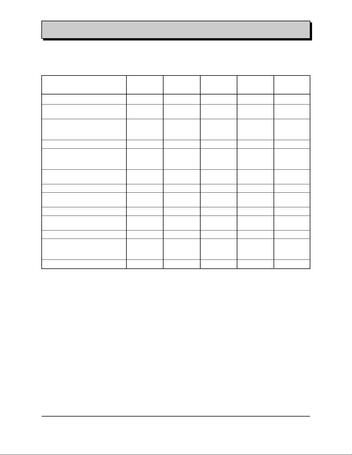
3.2.4.3 Operating Conditions and Measures
3.2.4.3.1 Heat Rejection
Heat rejection levels for combined engine coolant and oil are measured per GM Test #9
and are summarized in the table below. The values for the specific heat rejection to the
coolant and Lube oil are shown below in table 3.5.3.1-I.
RPM L35 L35 Condition
Truck Marine
Applications Applications
Heat rejection Heat rejection
BTU/Min BTU/Min
2000 1339 n/a Road Load
2800 2038 n/a Road Load
3600 2937 n/a Road Load
1600 1536 n/a 7.2% Grade
2400 2226 n/a 7.2% Grade
2000 2209 2336 WOT
3000 3001 3202 WOT
4000 3910 4274 WOT
4200 4080 4314 WOT
4400 4309 4799 WOT
4600 4460 4716 WOT
750 486 539 Idling
1300 1016 1074 Parked
2200 1756 1826 Parked
Table 3.5.3.1-I 4.3L V6 90 Degree Engine Heat Rejection
3.2.4.3.2 System Pressure
GMPT engines are designed to operate with a pressurized cooling system and surge tank.
System pressure is controlled with a spring loaded pressure (RC33) relief cap with a nominal
setting of 15 Psi.
File: c:\data\manuales\v6-truck\am43v6#3.doc
Contact:Luis Nespolo - (248) 857-1558 Printed: 8/15/00
51
Page 54

ENGINE APPLICATION MANUAL GM Powertrain
Gasoline 4.3L V6 90 Degree Revised: 08/15/2000
3.2.4.3.3 Coolant Operating Temperatures
This engine has been validated for continuous duty including continuous operation at
WOT with the coolant temperature under thermostat control (see thermostat start to
open and full open temperatures). Limited operation above thermostat full open
temperature is allowed as shown in the table below.
OPERATION MAX ALLOWABLE TEMP
Extended Idle (Up To 30 Minutes) In Ambient up to >38 C 262.4 F
City Traffic Operation In Ambient
- Up To 109.4 F 237.2 F
- Up To 118.4 F 255.2 F
Grades
- Trucks At GCW, 7.2% Grade, 100 F, Ambient 250 F
- Passenger Cars At GVW, 7.2% Grade, 100 F , Ambient 250 F
High Speed Operation
- Passenger Cars At GVW, 167 kph, Up To 48 C Ambient 237 F
Soaks Following Grade Operation 262 F
3.2.4.3.4 Flow Rates
Flow to the radiator and heater vary with pump speed, thermostat valve position, and
pressure drop across the heat exchangers.
RPM L35 Condition
All Applications
Coolant Flow
GPM
2000 32.5 Road Load
2800 46.1 Road Load
3600 59.9 Road Load
1600 26.1 7.2% Grade
2400 37.7 7.2% Grade
2000 32.6 WOT
3000 49.5 WOT
4000 66.6 WOT
4200 70.1 WOT
4400 73.6 WOT
4600 76.5 WOT
750 12.1 Idling
1300 21.2 Parked
2200 36.0 Parked
Figure: 3.2.4.3.4 - I - Water Pump Flow Rates
File: c:\data\manuales\v6-truck\am43v6#3.doc
Contact:Luis Nespolo - (248) 857-1558 Printed: 8/15/00
52
Page 55

ENGINE APPLICATION MANUAL GM Powertrain
Gasoline 4.3L V6 90 Degree Revised: 08/15/2000
3.2.4.3.5 Coolant Fill
Assembly Plant- GMPT requires the engine cooling system to be at least 95% filled
(from a dry system no bleed valves) before the engine is started.
Service- GMPT requires a clear unobstructed view of the coolant deaeration tank be
provided in an underhood location. The system should be designed to be capable of
replacing 95% of the coolant drained during a service situation without starting the
engine or opening any bleed valves.
3.2.4.3.5.1 System Drain Down
The system is to be designed to displace all air in the engine, hoses, heater(s), and
radiator into the deaeration tank while the engine is operating. After the engine,
upper radiator hose, and radiator are charged with coolant the charge must be
maintained at all times prior to low coolant light activation. The only air in the
cooling system should be located in the deaeration tank.
Letting air enter the engine, upper radiator hose, or radiator can allow coolant in the
system to drain down, which is unacceptable. Drain down can result in a false
indication of the coolant level at the deaeration tank.
It also forces the system to run aerated coolant for a short time after every cold start
while the engine, upper radiator hose, and radiator are recharged with coolant.
3.2.4.3.5.2 Service Fill/Procedure
Capability to fill the system to 95% or more of capacity without running the engine.
This ensures enough coolant is in the system to prevent engine damage if run for
extended periods of time without checking the coolant level. Rear heater systems
generally can not be filled without running the engine making it difficult to achieve a
90% static fill. However, rear heaters are difficult to drain as well and typically do
not have to be refilled during service fill. If the rear heater is drained, a few minutes
of running at moderate engine speeds is usually adequate to flush the air out of the
heater and achieve a 90% fill.
3.2.4.3.5.3 Fill Rate
The system should be able to achieve a 95% static fill at the 3 GPM rate.
This indicates adequate sizing of the deaeration tank fill line and proper venting of the
system.
3.2.4.3.5.4 Drawdown Capacity
The cooling system must be capable of losing approximately 10% or 2.4L (2.5 QTS.)
of coolant without aeration occurring or loss of flow. Run at 3500 RPM with a
blocked open thermostat.
This allows the engine to operate without damage when only a 95% fill is obtained.
3.2.4.3.5.5 Deaeration Capability
The ability for the system to run un-aerated within 20 minutes after a service fill.
Run with an operating thermostat and at 3500 RPM. The system needs to be able
to purge air into the deaeration tank during closed and partially open thermostat
conditions.
3.2.4.3.5.6 Air Handling Capability
The ability to lose no more than 50% of the water pump flow with 0.2 CFM of air injected
into the engine. The air is injected into an area after the water pump to simulate a
combustion leak into the coolant. Coolant loss during the test should not exceed the
Drawdown capacity. Test run at 3500 RPM with a blocked open thermostat.
3.2.4.3.5.7 Low Coolant Light Calibration
The low coolant light is to be calibrated to activate prior to coolant aeration
occurring. Normally the low coolant light should come on when the amount of
coolant lost is less than or equal to the Drawdown capacity.
In some installation (see 3.5.3.5.1) the Low Coolant Light will have to come on prior
to the Drawdown capacity to prevent drain down.
File: c:\data\manuales\v6-truck\am43v6#3.doc
Contact:Luis Nespolo - (248) 857-1558 Printed: 8/15/00
53
Page 56

ENGINE APPLICATION MANUAL GM Powertrain
Gasoline 4.3L V6 90 Degree Revised: 08/15/2000
3.2.4.4 Coolant and Heater Subsystem Descriptions
3.2.4.4.1 Coolant Inlet- Water Pump Inlet Restriction
Typical Diameter: 60 mm +/- 0.3 mm.
The suction at the water pump inlet should not exceed approximately 1.0" HG (-1.0" HG
pressure) when run at 3500 RPM without a pressure cap. Exceeding this suction could
cause the lower radiator hose to collapse if the system loses cap pressure.
3.2.4.4.2 Coolant OutletTypical Diameter: 46.2 mm +/- 0.3 mm.
3.2.4.4.3 Heater FeedTypical Diameter: 15.9 mm +/- 0.3 mm or 19.05 mm +/- 0.3 mm
3.2.4.4.4 Heater Return
Typical Diameter: 15.9 mm +/- 0.3 mm or 19.05 mm +/- 0.3 mm
3.2.4.4.5 Coolant Hose Material
GMPT requires hose material meeting GM specification 6140m, 6250m, 6278m, or
6149m (hose material specifications vary by the severity of the environment they will be
subjected to).
Reference radiator and heater hose dimensional specifications listed on drwg. #
12552514. Suggested lubricant for ease of hose assembly to inlet nipple is GM
9985406
3.2.4.4.6 Hose Clamps
GMPT requires the use of constant tension clamps for all hose connections.
Reference dimensional information on hose clamp drwg. # 11516215 and equivalents.
3.2.4.4.7 Thermostat
- start to open temperature- 170°F
- full open temperature- 190°F
File: c:\data\manuales\v6-truck\am43v6#3.doc
Contact:Luis Nespolo - (248) 857-1558 Printed: 8/15/00
54
Page 57

ENGINE APPLICATION MANUAL GM Powertrain
Gasoline 4.3L V6 90 Degree Revised: 08/15/2000
3.3.1 GMPT Interface with CHASSIS Fuel System
Figure 3.2.1-I to 3.2.1-XVIII shows the PCM Engine to Vehicle Mechanization Diagram with this
interface.
RPM L35 L35 Units
Truck Marine
Application Application
800 17.16 17.7 PPH
1200 26.45 27.3 PPH
1600 35.12 37.9 PPH
2000 44.17 46.7 PPH
2400 54.79 56.1 PPH
2800 64.74 67.9 PPH
3200 75.30 76.3 PPH
3600 84.40 85.1 PPH
4000 94.33 94.9 PPH
4400 102.80 104.3 PPH
4800 105.4 112.2 PPH
5200 106.97 119.0 PPH
Figure: 3.3.1 - I 4.3L V6 90 Degree Engine - Fuel requirements vs. Engine Speed
The following table shows the different Fuel Lines, Fuel Tank and Evaporative Assemblies and
Components coupled to the L35 engine per GM platforms.
Fuel P-Truck C/K Truck G-Van M/L -Van S/T Truck
( 8 A )
Pipe ASM Fuel N/A N/A 15030585 15000300 N/A
Pipe ASM Fuel Feed N/A N/A 15043227 15023800 15023800
15043228 15023801 15023801
15023802 15023802
Fitting Fuel Pipe 15550219 15550219 N/A 15036790 15036790
Hose 15733594 15765804 N/A 15054322 15054322
15035085 15765806
15721387
Fuel Filter 15530354 N/A 25121800 25171788 25171788
25055129
Bracket N/A 15013855 15009324 N/A N/A
Clip/Clamp 343449 343449 343449 343449 343449
15973085 15973085 15973085 15973085 15973085
15677730 15677730 15677730 15677730 15677730
Bolt/Screw/Nut/Stud 11515211 11515211 11515211 15604106 15604106
11516076 11516076 11516076 15708937 15708937
11508279 11508279 11508279 3932368 3932368
9428638 9428638
File: c:\data\manuales\v6-truck\am43v6#3.doc
Contact:Luis Nespolo - (248) 857-1558 Printed: 8/15/00
55
Page 58

ENGINE APPLICATION MANUAL GM Powertrain
Gasoline 4.3L V6 90 Degree Revised: 08/15/2000
Fuel Tank P-Truck C/K Truck G-Van M/L -Van S/T Truck
( 8 B )
Fuel Tank ASM with Pump N/A 15759638 15017931 15747872 15013150
15759639 15017932 15066407 15028431
15767150 15020046 15048831
15062877 15761468
15762977
15762978
Fuel Tank ASM no Pump 15721311 N/A N/A N/A N/A
Fuel Pump 25315352 N/A N/A 15062879 N/A
25314575
Fuel Valve 15978533 N/A N/A N/A N/A
Pipe Filler 15030687 15747585 15052676 15061623
15015206 15062980
15062981
Strap 15311568 15745095 15015617 15745065 15015589
15745096 15015618 15032208
15770877 15745014
15770878 15745015
Cap 22616285 15763225 15746557 22660002 22660002
Bolt/Screw/Nut/Stud 9428638 11516551 11516523 15604106 15604106
11518477 11516770 11518476 11508561 11508561
11517784
Fuel Evaporative P-Truck C/K Truck G-Van M/L -Van S/T Truck
( 8 D )
Canister ASM 17098106 15056485 17098085 17098085 17201171
17097127
17097120
Shield 15004076
Hose 10282447 15759042 N/A 15012787 9439150
15721451 15759043 15150414
15733597 15726983
15721447 15768562
15721448
15731510
Clamp 10108259 10108259 N/A 10108259 10108259
11516221 11516221 11516221 11516221
Separator 17096210 N/A 15032645 15032645 15032645
15032646 15032646 5032646
Bracket 15009801 15056490 15769694 15769694 15049107
15013689 15742240
15746404 15734230
17565062 15992101
15731699
Harness 12556909 12555973 12561900 12561900 11509087
12566190
Strap 11509087 11509087 15000499 11509087 11509087
Valve 12559015 15032643 15032643 15759225 25658328
15032644 15032644 12559015
Bolt/Screw/Nut 11508797 11516573 11515211 11515211 11515654
3847758 11513914 11508797 11508797 11515656
3975550 3847758 11515658
11515211 3975550
File: c:\data\manuales\v6-truck\am43v6#3.doc
Contact:Luis Nespolo - (248) 857-1558 Printed: 8/15/00
56
Page 59

ENGINE APPLICATION MANUAL GM Powertrain
Gasoline 4.3L V6 90 Degree Revised: 08/15/2000
3.3.2 GMPT interface with Air Induction System
3.3.2.1 Air Requirement
RPM L35 L35 Units
Truck Marine
Application Application
800 23.8 24.9 gr/sec
1200 37.8 39.3 gr/sec
1600 51.8 52.7 gr/sec
2000 65.8 67.4 gr/sec
2400 81.3 82.9 gr/sec
2800 97.7 99.0 gr/sec
3200 113.7 116.3 gr/sec
3600 128.8 130.5 gr/sec
4000 143.3 142.3 gr/sec
4400 154.7 154.0 gr/sec
4800 160.9 165.1 gr/sec
5200 163.7 175.0 gr/sec
Figure: 3.3.2.1-I 4.3L V6 90 Degree Engine Air Requirements
3.3.2.2 Air Flow Path
The air flow path in the vehicle at the air inlet of the air induction system shall not be
obstructed with vehicle components that will cause loss of pressure or flow disturbance.
All performance parameters specified in paragraph: 2.3.2.1 were measured with a maximum
air restriction of 1” of Hg.
As reference in table 3.3.2.1 - I, development power and torque data is shown to illustrate
the order of magnitude that may result as increasing the induction restriction.
Table 3.3.2.1 - I
4.3L V6
Development Peak Power and Torque Levels
Induction Restriction *
Induction Torque Power
Restriction (Lb.-Ft) (Hp)
1” Hg. 264 200
1.2” Hg. 262 198
1.4” Hg. 260 196
1.6” Hg. 258 194
* Exhaust backpressure held at 11” Hg.
File: c:\data\manuales\v6-truck\am43v6#3.doc
Contact:Luis Nespolo - (248) 857-1558 Printed: 8/15/00
57
Page 60

ENGINE APPLICATION MANUAL GM Powertrain
Gasoline 4.3L V6 90 Degree Revised: 08/15/2000
3.3.2.4 Temperature Rise
The intake of air must avoid the suction of air coming from the hot spot areas of the inside of
the engine bay such as proximity to exhaust manifold.
As referenced in table 3.3.2.4 - I, development power and torque data is shown to illustrate
the order of magnitude that may result as increasing the induction temperature.
Table 3.3.2.4 - I
4.3L V6
Development Power Variation and
Induction Temperature Increase
Inlet Air Temperature Power Loss
(Deg-F) (%)
77 0
90 2.7
100 5.1
122 8.5
144 11.6
176 16
208 20.3
3.3.2.4 Filtration Requirements
GMPT requires an air filtration medium that is capable of removing 98.7% of the material
contained in reference material SAE “Course Dust”.
The following table shows the different Air Cleaner ASM and Components coupled to the
L35 engine per GM platforms.
Engine Air Cleaner P-Truck C/K Truck G-Van M/L -Van S/T Truck
( 6 M 3 )
Air Cleaner 25147074 25322546 15754209 15747601 15747865
15766610 15747867
Bracket 15982176 15735434 25171130
15987694 15735435
Adapter 15997186
Bolt/Screw/Nut/Stud 3846202 11516484 11516727 15992646 15994910
11508300 11516589 11992647 11515933
11509542 11516587 11514596
14045263 15994910
15992647
15994910
Duct 15985845 15057511 15016578 25160175 25173868
15985846 25168087
15729512
15971184
15755160
15020026
Clamp 15986419 15986419
2465839 2465839
8868639 8868639
Elbow 15003750 15003750
15994899 15994899
File: c:\data\manuales\v6-truck\am43v6#3.doc
Contact:Luis Nespolo - (248) 857-1558 Printed: 8/15/00
58
Page 61

ENGINE APPLICATION MANUAL GM Powertrain
Gasoline 4.3L V6 90 Degree Revised: 08/15/2000
3.3.3 GMPT Interface with Oil Cooling Subsystem
3.3.3.1 Oil Cooler Requirements -
Heat Rejection to Oil - Consult GM Application Engineer.
The following table shows the different Oil Cooling, Filter Assemblies and Components
coupled to the L35 engine per GM platforms.
Oil Cooling P-Truck C/K Truck G-Van M/L -Van S/T Truck
( 6 G 3 )
Oil Cooler ASM 15722841 15021207 15021207 15021207 15021207
Oil Hose Cooler ASM 15007061 15736423 15736423 15764375 15760333
Bolt/Screw/Nut 9419683 9419683 9419683 9419683 9419683
11514139 11514139 11514139 11514139 11514139
15679508 15679508 15679508 15679508 15679508
Bracket 15557752
Bolt Screw w/Nut 11508253 11508253 11508253 11508253 11508253
11516071 11516071
Strap 11501907 15607246 15607246 15607246 15607246
Bracket 15996659 15029984 15029984 15029984 15029984
Bolt Screw 11509759 11515210 11515210 11504357 11504357
Connector 15719697 15719697
Oil Filter P-Truck C/K Truck G-Van M/L -Van S/T Truck
( 6 G 5 )
Filter 25170846 25014831 25014831 25014831 12556880
15026051
15026052
Adapter 12558731 3952301 3952301 3952301 12556880
12562830 12562831 12562831 12562831 15760334
Fitting N/A 3853870 3853870 3853870 15689615
Gasket 12551589 12551589 12551589 12551589 12551589
12552828 12552828 12552828 12552828 12552828
Bolt/Screw 10168445 3951644 3951644 3951644 11508253
9421634 9421634 9421634 11505347
15701734
File: c:\data\manuales\v6-truck\am43v6#3.doc
Contact:Luis Nespolo - (248) 857-1558 Printed: 8/15/00
59
Page 62

ENGINE APPLICATION MANUAL GM Powertrain
Gasoline 4.3L V6 90 Degree Revised: 08/15/2000
3.3.4 GMPT Interface with Chassis Engine Mountings
3.3.4.1 Engine Packaging Dimensions
The packaging dimensions for the 4.3L V6 90 Degree referenced from the center line of
crankshaft and the rear face of block are shown in the Figure 3.3.4.1-I. Adequate engine roll,
load, or thermal clearances (which ever is largest) should be added to these dimensions.
Figure 3.3.4.1 – L 4.3L V6 90 Degree Packaging Dimensions
3.3.4.2 Recommended Installation Angles
See Figure 3.3.4.2 for the vehicle installation angle description in a transverse powertrain
application.
Side View Front View Plan View
Figure 3.3.4.2 Installation Angles
3.3.4.2.1 Recommended Side View Angle
The a angle shown in powertrain side view shall not exceed 5 Degree. For greater
values consult GM Application Engineering.
3.3.4.2.2 Recommended Front View Angle
The b angle shown in powertrain front view shall not exceed 5 Degree. For greater
values consult GM Application Engineering.
3.3.4.2.3 Recommended Plan View Angle
The e angle shown in powertrain plan view shall not exceed 5 Degree. For greater
values consult GM Application Engineering.
File: c:\data\manuales\v6-truck\am43v6#3.doc
Contact:Luis Nespolo - (248) 857-1558 Printed: 8/15/00
60
Page 63

ENGINE APPLICATION MANUAL GM Powertrain
Gasoline 4.3L V6 90 Degree Revised: 08/15/2000
3.3.4.3 Rear Face of Block Configuration
The rear face of block is illustrated in Figure 3.3.4.3. Dimensions are from the center line of
crank.
Figure 3.3.4.3 Rear Face of Block
3.3.4.4 Ground Clearance
No engine component shall be positioned below the vehicle dynamic ground line.
File: c:\data\manuales\v6-truck\am43v6#3.doc
Contact:Luis Nespolo - (248) 857-1558 Printed: 8/15/00
61
Page 64

ENGINE APPLICATION MANUAL GM Powertrain
Gasoline 4.3L V6 90 Degree Revised: 08/15/2000
The following table 4.4.1-I shows the different Mounting Components coupled to the L35 engine
per GM platforms.
Powertrain Mounting P-Truck C/K Truck G-Van M/L -Van S/T Truck
( 6 Q )
Engine Mountings
Engine Mounting ASM 14031472 22174978 15017907 22112499 22173023
Engine Mounting ASM 15037192 22179440 15017908 22112500
Bolt Screw 9420462 11516941-2-3 11515765 11509141 9442966
9424320 11517017-8 25623779 15596428 11517706
6262211
Nut 9442946 9442946 9442946 11516077 15956061
9442947 9442947 9442947 9442947 9442947
9418897 9418897 9418897 9418897 9418897
Spacer 15160007 15160007 N/A N/A N/A
Bracket 15041538 15753409 15969182 22145863 15725993
6259949 15753410 15054180 15697577 15725994
Bracket 15953632 15753411 N/A 15708672
6259950 15708673
Bracket 15037193 15732463 N/A 15999045
Bracket 15557731 15732464 15999046
Bolt Screw 9433115 9433115 11509141 15672901
9420462 9420462 11509141
Bolt Screw 11517706 11517706
Washer 407795 407795
15531204 15531204
Shield 15037194 N/A 15764435-6 15977043
Transmission Mountings
Trans Mounting ASM M74 15683966 N/A
Bolt Screw 9441662
15592071
Washer 11505575
Nut 11516077
15151028
9442946
Trans Mounting ASM MT1 17990857 N/A 22179376-7 22145766 15767866
15717594
Bolt Screw 15592071 N/A 11515946 11500831 15726468
11514071
Washer 11505575 N/A N/A 11500046
11500223
Nut 11516077 N/A 11514521 11515552 11515552
Shields N/A N/A 15160656
Bolt Screw Shield N/A N/A 15712486
Trans Mounting ASM MG5 N/A 15761786 N/A
Bolt Screw N/A 15592071 N/A
Washer N/A 11505575 N/A
Nut N/A 11516077 N/A
Trans Mounting ASM M30 N/A 15768333 N/A
Bolt Screw N/A 15592071 N/A
Washer N/A 11505575 N/A
Nut N/A 11516077 N/A
File: c:\data\manuales\v6-truck\am43v6#3.doc
Contact:Luis Nespolo - (248) 857-1558 Printed: 8/15/00
62
Page 65

ENGINE APPLICATION MANUAL GM Powertrain
Gasoline 4.3L V6 90 Degree Revised: 08/15/2000
4.0 DETAILED PERFORMANCE DESCRIPTION
4.1 EXHAUST AND EVAPORATIVE EMISSIONS
4.1.1 EPA Certification
This engine when equipped with GMPT specified exhaust after treatment systems and GMPT
transmissions has been certified to EPA requirements
4.1.2 CARB Certification
This engine when equipped with GMPT specified exhaust after treatment systems and GMPT
transmissions has been certified to CARB requirements
4.1.3 Other Regulations
The Engine must comply with the following regulations: (Based on application and time of
production.)
GVWR # LVW# FEDERAL (TIER 1) (g/mile) CALIFORNIA (TIER 1) (g/mile)
3751 5750
6001 8500
5751 8500
NOx THC NMHC CO PM MILES NOx THC NMHC CO PM MILES
— — .32 4.4 — 50K .98 .45 6.4 .10 120K
.98 .80 .46 6.4 .10 120K
NOx THC NMHC CO PM MILES NOx THC NMHC CO PM MILES
— — .39 5.0 — 50K 1.53 .56 7.3 .12 120K
1.53 .80 .56 7.3 .12 120K
8501-
8501 14,000 10,000 - 4.0* 1.3* 15.5* NOx THC THC CO PM MILES
>14000 >14000 4.0* 1.9* 37.7* 3.9* 14.4* .10* 110K
10,000
14,000 4.0* 1.9* 37.7* 2.77 .86 10.3 .18 120K
NOx THC NMHC CO PM MILES NOx THC NMHC CO PM MILES
4.0* 1.3* 15.5* .10* 110K 1.81 .66 8.1 .15 120K
NOx THC NMHC CO PM MILES NOx THC THC CO PM MILES
OPT FOR DIESEL/INCOMPL.* (GVW 8501-14,000)
NOx & NHM C CO PM MILES
3.9* 14.4* .10* 110K
* g/bhp - hr
Figure: 4.1.1-I EPA Regulations
File: c:\data\manuales\v6-truck\am43v6#3.doc
Contact:Luis Nespolo - (248) 857-1558 Printed: 8/15/00
63
Page 66

ENGINE APPLICATION MANUAL GM Powertrain
Gasoline 4.3L V6 90 Degree Revised: 08/15/2000
4.1.3.1 Onboard Diagnostics
Onboard diagnostic refers to the ability of the Powertrain control system to self diagnose
emission performance related problems and communicate the existence of such problems to
the vehicle operator via the “Service Engine Soon” telltale light present in the vehicle
instrument panel, or to the service technician via a serial data communication tool attached
to what has been the Assembly Line Data Link (ALDL), but what is becoming an industry
standard “Class 2” serial data link per SAE J1850.
a. Improve in-use compliance with emission standards for the lifetime of the vehicle.
b. Detect & identify deterioration and malfunction of emission related components and
systems.
c. Augment/supplant current inspection/maintenance programs.
d. Detect deterioration or malfunction of individual emission related components.
e. Define a standardized electronic communication protocol to enable interrogation of the
control system so as to allow independent service stations the ability to diagnose and repair
emission related failures with communized electronic instruments across various
manufacturer’s product lines.
4.1.3.2 Applicability
Table 4.1.3.2 -1 defines the applicability of Federal OBD II requirements to Federally
emission certified full size GMTG vehicles.
GVWR (Lbs.) OBDII Compliance Requirements
EPA California
< 8500 Lbs. yes yes
8500 < GVWR < 14000 no N/a
> 14000 Lbs. N/a N/a
Table 4.1.3.2-I. Applicability of Federal/California OBD II Full-Size Vehicles
4.1.3.3 Requirements
Federal OBD II requirements may be categorized into two basic groups. The two groups
include:
a. Standardization requirements
b. Diagnostic Requirements specific to Federal OBD II
Requirement Description
Data Link Connector and Protocol SAEJ1850 - Specifics requirements for vehicle data
communications network. GM implementation of this
standard known as Class 2 Serial Data
SAEJ1962 - Specifies the new 16 pin under dash
diagnostic connector.
SAEJ1978 - Specifies the OBD II scan tool which is
designed to attach and communicate via the under
dash diagnostic connector.
Test Modes and Fault Codes SAEJ1979 - Specifies CARB/EPA functions and
messages
Parameter Information SAEJ2012 - Specifies format and messages for
diagnostic trouble codes
File: c:\data\manuales\v6-truck\am43v6#3.doc
Contact:Luis Nespolo - (248) 857-1558 Printed: 8/15/00
64
Page 67

ENGINE APPLICATION MANUAL GM Powertrain
Gasoline 4.3L V6 90 Degree Revised: 08/15/2000
5.0OPERATING ENVIRONMENT
5.1 ROADWAY GRADES, SURFACES AND HAZARDS
The careful selection of 4.3L V6 90 Degree Engine and Transmission in accordance with the proper
installation to the vehicle will assure the operation of the engine in a very wide range of roadway
grades, surfaces, hazard and Off Road conditions.
Altitude: The engine is designed to function at altitudes from 200ft (61M) below sea level to 14500ft
(4420M) above sea level.
Gradability: The engine is designed to function at grades -16<0< 16% GM Application engineering
will support the customer with applications out of this range.
5.2 CRITICAL COMPONENT TEMPERATURE LIMITS
The following table 5.2 shows Critical Component Temperature Limits as a reference value for
different components. The GM application will verify these values for each specific application. All
engine non-metallic components not listed in the table will withstand a minimum underhood
temperature of 121 Degree Celsius.
Component Temperature Range Excursion Temp (Deg. C)
Coolant Temperature Sensor -40 to 132 172
Aux. Cooling Fan Switch -40 to 132 172
ESC Sensor -50 to 135 185
Spark Plug Wire Conduit - Nylon -40 to 120 180
Spark Plug Wire Clips - Nylon 66 -40 to 135 200
Spark Plug Wire Boots - Hi Temp Silicone -40 to 232 272
Fuel Injectors -40 to 120 160
MAP Sensors -40 to 105 145
Fuel Rail -40 to 125 165
Coil Driver Module -40 to 125 165
Crank Sensor -40 to 150 165
Oxygen Sensor Connector -40 to 125 165
Starter Motor -40 to 121 161
High Voltage Switch & Internal CAM Sensor -40 to 150 165
ECM Coolant Sensor -40 to 155 195
Ignition Coil -40 to 105 145
MAF sensor -40 to 125 165
Throttle Body -40 to 120 160
Purge Valve -40 to 125 150
Evap. Tube -40 to 125 150
Canister -40 to 90 125
IAT Sensor -40 to 125 165
EGR & Internal -40 to 135 175
Oil Pressure Sensor -40 to 150 190
Ignition Cable -40 to 232 272
Block Heater -40 to 135 175
Bypass Coolant Hose -40 to 130 170
Exhaust Manifold & Components -40 to 950 1100
Underbody Attaching Harnesses/Connectors -40 to 125 165
Transmission to Engine Electrical Connectors -40 to 135 175
Oil Pan Gasket -40 to 150 190
Quick Connect Cooler Fitting Seal -40 to 150 190
Oil Pan Drain Plug Seal -40 to 150 190
NSBU Switch -40 to 150 190
Oil Mineral -30 to 128 150
Belts -40 to 121 121
File: c:\data\manuales\v6-truck\am43v6#3.doc
Contact:Luis Nespolo - (248) 857-1558 Printed: 8/15/00
65
Page 68

ENGINE APPLICATION MANUAL GM Powertrain
Gasoline 4.3L V6 90 Degree Revised: 08/15/2000
5.3 HUMIDITY, RELATIVE HUMIDITY (SEE CHART 5.2-I)
5.4 PRESSURE (SEE CHART 5.2-I)
The 4.3L V6 90 Degree Engine shall be able to withstand any combination of environment conditions
that it may be exposed to in 10 years.
For the purpose of this application manual the environment is defined as the 4.3L V6 90 Degree
Engine exposed during the percentage of his life to the conditions showed in the chart 5.2.1-I.
Table : 5.2.1-I Temperature Operating Environment
Functionality Minimum Maximum
Temperature Temperature
Operate, Start Unassisted -20 F 120 F
Operate, Start Assisted
(1) Assisted starts in the -20 to -40 degree Fahrenheit range shall be interpreted as meaning that the vehicle must start
under the defined condition with use of appropriate aids such as an RPO engine block heater, reduced viscosity oil, an
auxiliary battery and or battery blanket(s). In the 120 to 135 degree Fahrenheit range an assisted start is defined as
permitting a hot engine to cool down to a level at which it will restart.
The temperature of the different Subsystems configuring the 4.3L V6 90 Degree Engine during
operation might be appreciable different from the values indicated in the Chart 5.2.1-I but will never
jeopardize the engine performance .See paragraph 5.2 for component max. temperatures.
The GM Application Engineer will define the TBD values in correspondence with the test procedure
adopted by the customer.
5.5 Underhood/Underbody Car Wash
No actual or projected loss of function or performance of the engine system shall occur as a result of
operating the vehicle in a car wash environment.
5.6 Fording
Consult the GM Application Engineer for application in conditions during Fording Operations.
5.7 Sand And Dust Exposure
No actual or projected loss of function or performance of the engine system shall occur as a result of
operating the vehicle in a sandy or dusty environment when the recommended air induction system
maintenance is performed.
5.8 Gravel And Stone Chip Exposure
No actual or projected loss of function or performance of the engine system shall occur as a result of
operating the vehicle in a gravel and stone environment.
5.9 Ozone exposure
No actual or projected loss of function or performance of the engine system shall occur as a result of
operating the vehicle in an environment with ozone exposure.
5.10 Electromagnetic Environment
The 4.3L V6 90 Degree Engine System is tested to ensure that electromagnetic environmental
conditions would not interfere with engine performance.
5.11 Shock, Impact
During the course of the normal operating life of the vehicle, the engine may be exposed to shock
loading. The engine, when installed in the vehicle, will be able to withstand the following G forces.
These are considered as random singular occurrences and are not cyclic.
a. Vertical - 2g’s, b. Fore-Aft - 6g’s, c. Lateral - 2g’s.
(1)
-40 F 135 F
Chart 6.2.1-I Environment Definitions
File: c:\data\manuales\v6-truck\am43v6#3.doc
Contact:Luis Nespolo - (248) 857-1558 Printed: 8/15/00
66
Page 69

ENGINE APPLICATION MANUAL GM Powertrain
Gasoline 4.3L V6 90 Degree Revised: 08/15/2000
5.12 Vibration Powertrain Bending
Powertrain Bending is a source of low frequency noise (50-200 Hz) which results in vibration.
Powertrain bending is defined as the point of the powertrain’s first vertical or horizontal bending.
In the case of the 4.3L V6 90 Degree Engine, the 2nd and 3rd orders of vibration are considered. The
low frequency vibration generated by Powertrain bending can be transmitted through the mounts
and into the frame and body of the vehicle.
This induced energy can cause vibration of vehicle components, which set up objectionable
resonance for the driver and passengers. For this reason, it is desired to make the Powertrain
package stiff enough so the Powertrain bending occurs at an engine RPM outside of the normal
operating mode or driving conditions of the vehicle. The ideal situation is to target the powertrain’s
bending moment so it occurs past the engine’s maximum RPM.
The minimum Powertrain stiffness as measured in units of Hertz to accomplish this can be
determined from the following equation:
Min. Bending Frequency (Hz) = (Constant *) x (RPM Max. Rated) * Use constant from table 6.12.1-I.
60 sec.
Table 6.12.1-I. Significant Orders of Vibration
Engine Configuration Orders of Vibration Constant *
L4 2nd Order 2
V6 - 60° 2nd Order 2
V6 - 90° 2nd Order 2
V6 - L6 3rd Order 3
V8 - 90° 1st Order 1
V8 - 90° 1-1/2 Order 1.5
V8 - 90° 4th Order 4
Example: a. 4.3L V6 90 Degree Engine = (2) x (5000 RPM) = 166 Hz Bending Frequency
60 sec.
In the case of a 4.3L V6 90 Degree Engine, it is desired to have the Powertrain stiffness great enough
so the bending resonance occurs at or above 90 Hz when the Powertrain is installed in the vehicle.
If the 4th order of vibration is considered, it is necessary to move the bending resonance out past 240
Hz to assure no resonance occurs within the engine operating speed. Since this is impractical
because of the design of the engine block and transmission housing, it is desirable to tailor the
component design so the bending resonance does not occur at idle or between 1800 and 2500 RPM.
See GM Application Engineer for further analysis.
File: c:\data\manuales\v6-truck\am43v6#3.doc
Contact:Luis Nespolo - (248) 857-1558 Printed: 8/15/00
67
Page 70

ENGINE APPLICATION MANUAL GM Powertrain
Gasoline 4.3L V6 90 Degree Revised: 08/15/2000
File: c:\data\manuales\v6-truck\am43v6#3.doc
Contact:Luis Nespolo - (248) 857-1558 Printed: 8/15/00
68
Page 71

ENGINE APPLICATION MANUAL GM Powertrain
Gasoline 4.3L V6 90 Degree Revised: 08/15/2000
6.0RECOMMENDED USAGE CONSTRAINTS
The following defines the outer limits of the envelope of operation that this engine has been validated to
(for its original application). Due to the extreme variation of potential usages, the attached information
should only be used as a guide toward pursuing alternate applications. Operation “outside” of the
described envelope should not be attempted without extensive testing and guidance from product
engineering. Data monitoring and providing shutdown capability would provide additional assurance that
the application’s intended envelope is not violated. The following parameters warrant measurement
consideration.
• Engine Speed -PCM controlled and monitored- Dash Light Sign
• Oil Temperature -Dash Light Sign
• Coolant Temperature -PCM controlled and monitored- Dash Light Sign
• Coolant Level -Dash Light Sign
6.1 ENGINE PRE-CONDITIONING PRIOR TO NORMAL OPERATION
No towing or continuous WOT operations for the first 500 miles or 12 hours.
6.2 ENGINE SPEED
Engine speed range has the ability to impact vehicle fuel economy, durability, and driveability
performance, particularly under heavy load.
The engine will provide the following speed dynamic range values shown in Table 2.2.3-II.
6.2.2 Maximum Start Time.
Engine start time is directly affected by the design of the starting subsystem. The starting
subsystem parameters include starter efficiency, battery cable length, battery cable gauge,
corrosion resistance and conductivity of cable connectors and battery cold cranking capacity.
The vehicle will start within the maximum times specified in Table 6.2.2 -I and continue to run at idle.
Table 6.2.2-I Maximum Start Time by Temperature
120 to 0 F 1 sec.
0 to -20 F 2 sec.
Table 6.2.2 -I 4.3L V6 90 Degree Engine Cranking
For temperature operating environment see table 5.2.1-I.
All starting times require at least 80% battery charge.
A starting aid (block heater) is required below -20°F.
Ignition voltage to PCM must be maintained at or above 7 volts during cranking.
6.2.3 Idle Quality (Speed and Stability)
6.2.3.1 Idle Stability
The PCM algorithm modifies fuel pulse and engine parameters to create smooth engine
idling at the values specified by the application engineer.
6.2.3.2 Idle Speed
The idle speed selected shall comprehend other subsystem requirements (i.e. cooling,
electrical, noise, accessory drive, etc. and be developed in the vehicle).
The engine idle speed will be targeted at the values shown in table 6.2.3.2-I to minimize fuel
consumption and emissions.
File: c:\data\manuales\v6-truck\am43v6#3.doc
Contact:Luis Nespolo - (248) 857-1558 Printed: 8/15/00
69
Page 72

ENGINE APPLICATION MANUAL GM Powertrain
Gasoline 4.3L V6 90 Degree Revised: 08/15/2000
Engine Speed Condition L35
Idle Speed Auto Transmission 575 rpm
Idle Speed Manual Transmission 525 rpm
Maximum Upshift 5200 rpm
Maximum Upshift
Hysteresis 5200 rpm
Table 6.2.3.2 -I V 6 Speed Dynamic Range
a) Operation at normal operating coolant temperature ( Range : 80 -128 ∞C)
Maximum Transient (W.O.T.) 5200 RPM
Minimum Transient (W.O.T.) 600 RPM
Instantaneous Maximum 5200 RPM
Continuous Maximum 4600 RPM
b) Operation at cold coolant temperature
Maximum @ - 28°C 4600 RPM
c) Operation at hot coolant temperature
Maximum @ 128°C 4600 RPM
File: c:\data\manuales\v6-truck\am43v6#3.doc
Contact:Luis Nespolo - (248) 857-1558 Printed: 8/15/00
70
Page 73

ENGINE APPLICATION MANUAL GM Powertrain
Gasoline 4.3L V6 90 Degree Revised: 08/15/2000
6.3 ENGINE LOAD
Sustained high engine loads (loads in excess of 90% of W.O. T. torque) should not be applied below
peak torque - engine rpm, See paragraph 2.3.2.1.
Torque Fluctuations.
Torque Fluctuations at WOT, will not exceed a value of ± 5% of the nominal torque value between
1000 RPM & max. rated speed.
Brake Specific Fuel Consumption
The engine brake specific fuel consumption (bsfc) shall be as follows:
1. The engines nominal brake specific fuel consumption point on a W.O.T. curve is shown in
table 6.3 -I.
2. The engine nominal specific fuel consumption shown in table 7.3 -I are for an operating range
between peak torque and maximum power at full load.
3. The engines best part throttle bsfc (on a fuel map) is shown in table 7.3 -I.
RPM L35 L35 Notes
Truck Marine
Applications Applications
800 0.529 0.495 lb./BHP-Hr
1200 0.521 0.478 lb./BHP-Hr
1600 0.484 0.481 lb./BHP-Hr
2000 0.470 0.471 lb./BHP-Hr
2400 0.471 0.466 lb./BHP-Hr
2800 0.469 0.472 lb./BHP-Hr
3200 0.478 0.458 lb./BHP-Hr
3600 0.483 0.452 lb./BHP-Hr
4000 0.500 0.460 lb./BHP-Hr
4400 0.525 0.479 lb./BHP-Hr
4800 0.532 0.506 lb./BHP-Hr
5200 0.556 0.550 lb./BHP-Hr
Table 6.3 -I V6 4.3L Engine BSFC
Engine Brake Capacity
FMVSS requires engine braking in at least one of the lower ratios, below 25mph.
For a transmission type similar to the 4L60-E this is equivalent to 2nd gear. For another type of
transmission combination the braking capability should be verified.
For manual transmissions, engine braking is calibrated with the GM transmissions to occur in the
highest ratio in each forward selector range
Some off road applications or very heavy load situations might require additional subsystems to
increase engine brake capacity.
Depending on the application, the GM release engineer and the customer will determine the
necessity of auxiliary or additional engine brake aid sub systems.
File: c:\data\manuales\v6-truck\am43v6#3.doc
Contact:Luis Nespolo - (248) 857-1558 Printed: 8/15/00
71
Page 74

ENGINE APPLICATION MANUAL GM Powertrain
Gasoline 4.3L V6 90 Degree Revised: 08/15/2000
6.4 OIL & CRANKCASE VENTILATION
Ambient Operating Temperature
-30°C to 128°C:use SAE 5W-30
Oil Quality: Use oil that meets the CF-2 quality standards of the API
Crankcase Ventilation
PCV Positive Crankcase Ventilation is used in the 4.3L V6 90 Degree.
6.5 COOLANT:
Coolant (See 3.5 Cooling/Heater)
Ethylene Glycol water mix 52/48 (normal) up to maximum of 60% glycol, 40% water
Coolant Temperature : See Section 3.5
Coolant Pressure: See Section 3.5
Warm-Up Rate: See Section 2.3.2.3.4
6.6 COMBUSTION CONTROL
All combustion controlled parameters are adjusted automatically through the PCM
7.0 QUALITY, RELIABILITY, & DURABILITY (QRD)
7.1 QUALITY AND RELIABILITY
Minimum Level of warranty is 12 month and 12000 miles, but there are available alternative warranty
plans throughout the GMPT and GM Service Group.
7.2 DURABILITY - USEFUL LIFE
Usage Mileage Years
4.3L (Light Duty) Unleaded Fuel 120,000 10
Useful Life Definition
File: c:\data\manuales\v6-truck\am43v6#3.doc
Contact:Luis Nespolo - (248) 857-1558 Printed: 8/15/00
72
Page 75

ENGINE APPLICATION MANUAL GM Powertrain
Gasoline 4.3L V6 90 Degree Revised: 08/15/2000
8.0SERVICE REQUIREMENTS
8.1 MAINTENANCE SCHEDULES (SEVERE USAGE AND NON SEVERE USAGE).
There are two maintenance schedules applicable to the 4.3L V6 90 Degree Engine.
These maintenance schedules relate to severe usage and non-severe usage.
8.1.1 Maintenance Schedules - Severe Usage (Schedule I)
Severe usage or short trip/city shall continue to be defined by the following description of typical
operation in the vehicle’s owner’s manual:
- Most trips are less than 4 miles (6km);
- Most trips are less than 10 miles (16km), and the ambient temperature is below freezing
- The engine is at low speed most of the time (door to door delivery, stop and go traffic,
commercial use)
- The vehicle is operated in dusty areas or off road frequently;
- The vehicle is used to tow a trailer
8.1.2 Maintenance Schedule - Non Severe or Long Trip/Highway Usage (Schedule II)
Long trip/highway shall continue to be defined in the vehicle owner’s manual as all typical
vehicle usage not defined to be included in the severe usage schedule.
8.2 SERVICE INTERVAL BY SCHEDULE
The service intervals for engine related service are defined in Table 8.2 - 1 as a function of vehicle
usage category, i.e. short trip/city usage or long trip/ highway usage.
Table : 8.2 - I Routine Service Interval by Usage
Item Schedule I Schedule II Schedule 1 Schedule II
(<8500 GVWR) (<8500 GVWR) (>8500 GVWR) (>8500 GVWR)
Engine Oil and Filter 3000 miles/3 month 7500 miles/12months 3000 miles/3 month 7500 miles/12months
Or on condition Or on condition Or on condition Or on condition
detected by oil detected by oil detected by oil detected by oil
quality monitoring quality monitoring quality monitoring quality monitoring
system system system system
Engine Coolant 50000 miles 50000 miles 50000 miles 50000 miles
Air Cleaner Filter 30000 miles 30000 miles 24000 miles 24000 miles
Spark Plug 100000 miles 100000 miles 100000 miles 100000 miles
Engine Wire ASM 100000 miles 100000 miles 100000 miles 100000 miles
Accessory Drive Belt 100000 miles 100000 miles 100000 miles 100000 miles
9.0 DIAGNOSTICS
Diagnosis shall be accomplished using industry standard electronic diagnosis tools such as Techline
Equipment (Tech 1/Tech 2 / Tech XS / CAMS).
10.0 OTHER AVAILABLE DOCUMENTS
The Application engineer will supply all technical documents needed to support the application and
validation process.
File: c:\data\manuales\v6-truck\am43v6#3.doc
Contact:Luis Nespolo - (248) 857-1558 Printed: 8/15/00
73
Page 76

ENGINE APPLICATION MANUAL GM Powertrain
Gasoline 4.3L V6 90 Degree Revised: 08/15/2000
File: c:\data\manuales\v6-truck\am43v6#3.doc
Contact:Luis Nespolo - (248) 857-1558 Printed: 8/15/00
74
Page 77

ENGINE APPLICATION MANUAL GM Powertrain
Gasoline 4.3L V6 90 Degree Revised: 08/15/2000
11.0 VALIDATION REQUIREMENTS
11.1 GENERAL
The validation of GM Powertrain units may follow a wide variety of validation procedures.
GMPT will participate with the customer in establishing the validation procedure needed to validate
the application of the V6 Gasoline Engine into the customer vehicle.
11.2 METHODS
When required, The GM Application and the Customer Release Engineer will determine a method of
design validation from the four acceptable methods listed below.
A: Validation by Analysis: 1) Simulation of the product (or its functions) or manufacturing
process and the specified conditions using mathematical
representation (math models, algorithms, equations, etc.), in
accordance with a procedure, and documenting the results
to ensure that a particular requirement has been met.
2) The generation of conclusions through the examination of
known data to ensure that a particular requirement has been
met.
I: Validation by Inspection: Examination of the product or manufacturing process, in
accordance with a procedure, and documenting specified
physical characteristics to ensure that a particular requirement
has been met.
D: Validation by Demonstration: Exercising the product or manufacturing process under specified
conditions, in accordance with a procedure, and documenting
the results to ensure that a particular requirement has been met.
T: Validation by Test: Exercising the product or manufacturing process under specified
conditions, in accordance with a procedure, collecting
quantitative data via instrumentation and documenting the
results to ensure that a particular requirement has been met.
11.3 VALIDATION DETAILS
Inspection and testing will be required to demonstrate that each V6 Gasoline Engine application is
adequate for the duty cycle and life demanded by the end user. This will take place as part of the initial
release process, and for significant changes to either the engine, transmission or vehicle systems.
Validation Methods of each application of the V6 4.3L Gasoline Engine will be applied at minimum to
the following issues:
11.3.1 Installation Review
The installation of the engine shall be validated and verified by comparison with the engineering
drawings created by vehicle manufacturer.
11.3.2 Emissions Test
To be negotiated between GM and Customer
11.3.3 Cooling System Performance Test
Cooling Subsystem Performance Test must be approved by the GM application engineer.
11.3.4 Water Snow Inhalation Performance Test
Test shall be performed to verify water and or snow can not be ingested by the engine.
11.3.5 Design Review/ Mockup
During the design installation process of the V6 Gasoline Engine into a vehicle, the GM
Application Engineer will indicate those areas that need design validation prior to construction.
File: c:\data\manuales\v6-truck\am43v6#3.doc
Contact:Luis Nespolo - (248) 857-1558 Printed: 8/15/00
75
Page 78

ENGINE APPLICATION MANUAL GM Powertrain
Gasoline 4.3L V6 90 Degree Revised: 08/15/2000
11.3.6 Underhood Temperature Measurements and Locations
Locations and Results performed by vehicle manufacturer shall be supplied to GMPT Application
Engineer
11.3.14 On Road Vehicle Test
This test will reflects performance requirements for speed, load, torque, power, and performance
of cooling system.
GMPT Application Engineer will provide vehicle level test specifications to the vehicle
manufacturer.
The vehicle manufacturer will execute physical test and provide test results approval by GMPT
Application Engineer.
File: c:\data\manuales\v6-truck\am43v6#3.doc
Contact:Luis Nespolo - (248) 857-1558 Printed: 8/15/00
76
Page 79

ENGINE APPLICATION MANUAL GM Powertrain
Gasoline 4.3L V6 90 Degree Revised: 08/15/2000
12.0 NOTES
12.1 ACRONYMS, ABBREVIATIONS, AND SYMBOLS
adv advance CAD Computer Aided Design
A/F Air -Fuel ratio CFR Cooperative Fuel Research
AIR Air Injection Reaction COE Council of Expertise
ASTM American Society for Testing Materials Corr corrected
API American Petroleum Institute COV coefficient of variation
ATDC after top dead center CR compression ratio
avg average CReff effective compression ratio
ACG Allied Component Group Cyl cylinder
B barometric pressure CNG Compressed Natural Gas
BMEP brake mean effective pressure
BP brake power
BSFC brake specific fuel D density
BSHC brake specific hydrocarbons Deg Degree
BSHR brake specific heat rejection Dia diameter
BSCO brake specific Carbon Monoxide
BSPM brake specific Particulate Mass
BSNOx brake specific NOx (oxides of nitrogen)
BTDC before top dead center
E engine displacement N polytropic compression coefficient
ECM Electronic Control Unit N Engine Speed
econ economy N2 Nitrogen
EEC European Economic Community NAO North American Operations
EFE Early Fuel Evaporation N/V Engine Speed/Vehicle Speed
eff efficiency NMEP Net Mean Effective Pressure
EFI Electronic Fuel Injection NMOG Non Methane Organic Gas
EGR Exhaust Gas Recirculation No. number
EPA Environmental Protection Agency
ESC Electronic Spark Control
exh Exhaust
exp experimental Obs observed
FMEP Friction Mean Effective Pressure OD outside diameter
FP Friction Power
FESM Front End Sheet Metal P Power
FMVSS Federal Motor Vehicle Safety Standards PCV Positive Crankcase Ventilation
GM General Motors PMEP Pumping Mean Effective Pressure
GMPT General Motors Powertrain PN Part Number
GMTG General Motors Truck Group
GPA Gas Processors Association Program PON Pump Octane Number
GVWR Gross Vehicle Weight Rating PP Peak Pressure
GMUTS General Motors Uniform Test Specifications PT Part Throttle
GPH Gallons Per Hour PCM Powertrain Control Module
HC hydrocarbon PTO Power Take-Off
H/C Hydrogen-Carbon ratio
Hz Hertz (frequency) QFD Quality Function Deployment
CEA Change Engineering Authorization
O/C Oxygen-Carbon ratio
PFI Port Fuel Injection
P/S Power Steering
IPTV Initial Defects Per Thousand Vehicle R Torque Scale Arm
IAC Idle Air Control RAT Radial Aperture Tube
ID inside diameter Rev revolution
IMEP Indicated Mean Effective Pressure RLP Road Load Power
int Intake RON Research Octane Number
IP Indicated Power RPO Regular Production Option
ISC Idle Speed Control RTD Resistive Temperature Detector
ISO Interl. Orgn. for Standardization RVP Reid Vapor Pressure
KT Knock threshold
File: c:\data\manuales\v6-truck\am43v6#3.doc
Contact:Luis Nespolo - (248) 857-1558 Printed: 8/15/00
RPM Revolutions Per Minute
77
Page 80

ENGINE APPLICATION MANUAL GM Powertrain
Gasoline 4.3L V6 90 Degree Revised: 08/15/2000
L stabilized dynamometer load VTS Vehicle Technical Specification
LBT Leanest Mixture for Best Torque VDP Vehicle Development Process (4-Phase)
LFE Laminar Flow Element VCM Vehicle Control Module
LPG Liquefied Petroleum Gas VE Volumetric Efficiency
LPP Location of Peak Pressure WOT Wide Open Throttle
MAP Manifold Absolute Pressure SAE Society of Automotive Engineers
max maximum ser no. serial number
MBT Minimum Spark Advance for Best Torque sg specific gravity
ME Mechanical Efficiency SI International System of Units
MEP Mean Effective Pressure std standard
m(a) air mass flow rate SSTS Subsystem Technical Specification
m(f) fuel mass flow rate
MMEP motoring Mean Effective Pressure T Torque
MON Motor Octane Number TBI Throttle Body Injection
MT Motoring Torque TDC Top Dead Center
MIL Malfunction Indicator Lamp TPS Throttle Position Sensor
WVRM World Vehicle Regulation Manual
TM Torque Management
TWO Test Work Order
File: c:\data\manuales\v6-truck\am43v6#3.doc
Contact:Luis Nespolo - (248) 857-1558 Printed: 8/15/00
78
Page 81

ENGINE APPLICATION MANUAL GM Powertrain
Gasoline 4.3L V6 90 Degree Revised: 08/15/2000
APPENDIX I
Engine-Vehicle Definition Form UNITS
VEHICLE PERFORMANCE
REQUIREMENTS
Maximum Speed on 1st Gear mph
Maximum Speed on 2nd Gear mph
Maximum Speed on 3rd Gear mph
Maximum Speed on 4th Gear mph
Maximum Speed on 5th Gear mph
Maximum Speed on Highway Mph
Body type
Body Cx
Body Width Ft
Body Height Ft
Body Length Ft
Body Frontal Area Sq. ft
Curb Weight Lbs
Gross Weight Lbs
Total weight Lbs
Maximum Acceleration (0-60mph)
Maximum Gradient %
CHASSIS
Single Axle Single Speed Ratio
Single Axle Double Speed - Low Ratio
Single Axle Double Speed - High Ratio
Tandem Axle Single Speed Ratio
Tandem Axle Double Speed - Low Ratio
Tandem Axle Double Speed - High Ratio
Driveline Efficiency
Single Axle Single Speed
Single Axle Double Speed
Tandem Axle Single Speed
Tandem Axle Double Speed
Wheelbase in
Tire Specification
Tire Footprint Development ft
Tire Maximum Speed rpm
File: c:\data\manuales\v6-truck\am43v6#3.doc
Contact:Luis Nespolo - (248) 857-1558 Printed: 8/15/00
79
Page 82

ENGINE APPLICATION MANUAL GM Powertrain
Gasoline 4.3L V6 90 Degree Revised: 08/15/2000
Engine-Vehicle Definition Form UNITS
TRANSMISSION
Manual transmission
1st Gear Ratio
2nd Gear Ratio
3rd Gear Ratio
4th Gear Ratio
5th Gear Ratio
6th Gear Ratio
Automatic transmission
1st Gear Ratio
2nd Gear Ratio
3rd Gear Ratio
4th Gear Ratio
5th Gear Ratio
6th Gear Ratio
Accessories
Accessory #1:
Accessory #1 Location:
Accessory #1 Type Drive:
Accessory #1 Hp required:
Accessory #2:
Accessory #2 Location:
Accessory #2 Type Drive:
Accessory #2 Hp required:
Accessory #3:
Accessory #3 Location:
Accessory #3 Type Drive:
Accessory #3 Hp required:
Accessory #4:
Accessory #4 Location:
Accessory #4 Type Drive:
Accessory #4 Hp required:
Vehicle Power & Torque Requirements Rolling Power Grade Power Aerodyn. Power Total
For Maximum Grade Requirements Requirements Requirements Power
Speed (MPH) K W V (1+ f)/ 375 G W V / 375 (100) 0.00256 C A V
hp hp hp Hp
3
10
15
20
25
30
35
40
45
Power for maximum Grade
Torque for maximum Grade
File: c:\data\manuales\v6-truck\am43v6#3.doc
Contact:Luis Nespolo - (248) 857-1558 Printed: 8/15/00
80
Page 83

ENGINE APPLICATION MANUAL GM Powertrain
Gasoline 4.3L V6 90 Degree Revised: 08/15/2000
Engine-Vehicle Definition Form UNITS
TRANSMISSION
Manual transmission
1st Gear Ratio
2nd Gear Ratio
3rd Gear Ratio
4th Gear Ratio
5th Gear Ratio
6th Gear Ratio
Automatic transmission
1st Gear Ratio
2nd Gear Ratio
3rd Gear Ratio
4th Gear Ratio
5th Gear Ratio
6th Gear Ratio
Accessories
Accessory #1:
Accessory #1 Location:
Accessory #1 Type Drive:
Accessory #1 Hp required:
Accessory #2:
Accessory #2 Location:
Accessory #2 Type Drive:
Accessory #2 Hp required:
Accessory #3:
Accessory #3 Location:
Accessory #3 Type Drive:
Accessory #3 Hp required:
Accessory #4:
Accessory #4 Location:
Accessory #4 Type Drive:
Accessory #4 Hp required:
Vehicle Power & Torque Requirements Rolling Power Grade Power Aerodyn. Power Total
For Maximum Grade Requirements Requirements Requirements Power
Speed (MPH) K W V (1+ f)/ 375 G W V / 375 (100) 0.00256 C A V
hp hp hp Hp
3
10
15
20
25
30
35
40
45
Power for maximum Grade
Torque for maximum Grade
File: c:\data\manuales\v6-truck\am43v6#3.doc
Contact:Luis Nespolo - (248) 857-1558 Printed: 8/15/00
81
Page 84

ENGINE APPLICATION MANUAL GM Powertrain
Gasoline 4.3L V6 90 Degree Revised: 08/15/2000
Engine-Vehicle Definition Form UNITS
Vehicle Power & Torque Requirements Rolling Power Grade Power Aerodyn. Power Total
For Maximum Speed Requirements Requirements Requirements Power
Speed (MPH) K W V (1+ f)/ 375 G W V / 375 (100) 0.00256 C A V
3
hp hp hp hp
10
20
30
40
50
60
70
80
90
100
Power for maximum Speed
Torque for maximum Speed
Vehicle Cooling System
Radiator: Make: M/N # : P/N:
Size: Height: Width: Thickness:
Number of Rows of Tubes: Fins/In.
Minimum Radiator Frontal Area Sq. Meter
Radiator Total Area Sq. Meter
Radiator Heat Evacuation Capacity BTU/Min
Maximum Radiator Coolant Flow GPM
Maximum Radiator Peak Pressure bar
Radiator Coolant inlet Size mm
Radiator Coolant Outlet Size mm
Surge Tank Make: M/N # : Location:
Capacity: Hose Size:
Deareation Tank Make: M/N # : Location:
Capacity: Hose Size:
Recovery Bottle Make: M/N # : Location:
Capacity: Hose Size:
Low Coolant Sensor Type
Low Coolant Sensor Location
Describe Deareation System: Lines Sizes: Location:
Describe obstruction to water flow:
Vehicle Heater Core: Make: Type: Location:
Auxiliary Heaters: Make: Type: Location:
Shutoff or By-Pass Valve:
Air Bleeds: Sq. Meter
Heater Hose Routing: Sq. Meter
Fan Make: M/N#: Max. Speed:
Fan Type:
Fan Drive Solid/Viscous Clutch: Drive Ratio:
Suction / Blower Diameter Blades #
Vehicle Electrical System
Battery Make: M/N # : Location:
Voltage Amperage Ambient
Voltage Amperage Cold
File: c:\data\manuales\v6-truck\am43v6#3.doc
Contact:Luis Nespolo - (248) 857-1558 Printed: 8/15/00
82
Page 85

ENGINE APPLICATION MANUAL GM Powertrain
Gasoline 4.3L V6 90 Degree Revised: 08/15/2000
Engine-Vehicle Definition Form UNITS
Alternator Make: M/N # : Location: Nominal
Voltage Amperage
Starter Make: M/N # : Location: Nominal
Power: Amperage:
Vehicle Oil System
Remote Filter: Type: Capacity:
Location & Measured height relative to
bottom of cylinder block
Oil Radiator Capacity
Radiator Number of Rows
Radiator Number of Tubes
Minimum Radiator Frontal Area Sq. Meter
Radiator Total Area Sq. Meter
Radiator Heat Evacuation Capacity BTU/Min
Maximum Radiator Coolant Flow GPM
Maximum Radiator Peak Pressure bar
Radiator Coolant inlet Size mm
Radiator Coolant Outlet Size mm
Vehicle Fuel System
Fuel Tank Material: Type: Capacity:
Fuel Lines Inlet Size: Length; Material:
Fuel Lines Return Size: Length; Material:
Height of Fuel Tank to Fuel Pump
Fuel Tank Cap Relief Pressure
Fuel Supply Pump
Type Make: Pressure: Flow:
Inlet Restriction @ Pump
Additional Comments
Air System
Air Cleaner Make: Type: Model:
Cleaner location Size: Length: Material:
Air Inlet Restriction @FL/NL:
Vehicle Exhaust System
Type : Single/Dual Pipe Size: Material: Make:
Muffler: Size: Material: Make:
Muffler/ Pipe Connection: Location: Flex / Solid:
Catalytic Converter Size: Material: Make:
@FL/NL: Location:
Exhaust Back Pressure @FL/NL: Location:
File: c:\data\manuales\v6-truck\am43v6#3.doc
Contact:Luis Nespolo - (248) 857-1558 Printed: 8/15/00
83
Page 86

ENGINE APPLICATION MANUAL GM Powertrain
Gasoline 4.3L V6 90 Degree Revised: 08/15/2000
File: c:\data\manuales\v6-truck\am43v6#3.doc
Contact:Luis Nespolo - (248) 857-1558 Printed: 8/15/00
84
Page 87

ENGINE APPLICATION MANUAL GM Powertrain
Gasoline 4.3L V6 90 Degree Revised: 08/15/2000
Contact:Luis Nespolo - (248) 857-1558 Printed: 8/15/00
ii
Page 88

ENGINE APPLICATION MANUAL GM Powertrain
Gasoline 4.3L V6 90 Degree Revised: 08/15/2000
PREFACE
This document will assist the reader in the application of the 4.3L V6 90 Degree Engine to the vehicle.
It gives an overview of the engine, its features, as well as focus on the systems, subsystems and
attachments that interface between the engine and the vehicle.
The performance of the 4.3L V6 90 Degree Engine is dependent on the design and processing of the
interface systems and their components.
Definitions:
The number between bracket shows the Specification level.
VTS: Vehicle Technical Specification. Level (1) SSTS.
Powertrain SSTS: Powertrain Subsystem Technical Specification. Level (2) SSTS.
Composed of Engine, Transmission and Controls, Similar to the other NAO Major Technical
Subsystems, like Electrical, HVAC, Chassis, Body, etc.
Engine SSTS: Engine Subsystem Technical Specification. Level (3) SSTS.
Transmission SSTS: Transmission Subsystem Technical Specification. Level (3) SSTS.
Controls SSTS: Controls Subsystem Technical Specification. Level (3) SSTS.
Cylinder Head SSTS: Cylinder Head Subsystem Technical Specification. Level (4) SSTS.
Piston CTS: Piston Component Technical Specification. Level (5) SSTS.
ACE: Assistant Chief Engineer, AE: Application Engineer, DRE: Design Release Engineer, PTVSE:
Powertrain Vehicle System Engineer.
The Word Subsystem is used in this context to indicate that a System Level (2) is part of a major System
Level (1).
The diagram 1.1 - I shows the scope of this specification with a dot line around the subsystems in which
it place precedence.
Diagram 1.1-I Powertrain SSTS scope of work
Contact:Luis Nespolo - (248) 857-1558 Printed: 8/15/00
iii
Page 89

ENGINE APPLICATION MANUAL GM Powertrain
Gasoline 4.3L V6 90 Degree Revised: 08/15/2000
GM Powertrain needs a thorough understanding of each application for the 4.3L V6 90 Degree Engine,
including for example, vehicle mass, transmission performance details, vehicle speed and grade as well
as vehicle cooling and air intake capabilities.
The OEM customer shall submit a completed “ Model Definition Form”, supplied by GM Powertrain at the
start of each project or equivalent “ Vehicle Powertrain Technical Requirement Specification” for each
project.
A sample form of the former appears as a supplement to this manual. (See Appendix I)
This data from the Model Definition Form, and the requirements contained within this manual, will be
used to generate an agreed specification for the complete 4.3L V6 90 Degree Engine.
All the dimensions and values in this manual are for reference only.
Refer to the appropriate 4.3L V6 90 Degree Engine installation drawing(s) for definitive information.
The following table summarizes the organization of the document.
Section Comments
1.0 Introduction
2.0 Product Summary Summarizes the Product Information, Provides
Feature Location Illustrations, and Characterizes
the Engine Content as Delivered.
3.0 Major System and Interface Descriptions Provides the “context” the Engine Operates
Within.
4.0 Vehicle Mounting and Packaging Details Mounting and Packaging.
5.0 Detailed Performance Description Provides Details on the Performance of the
Engine as an Overall System.
6.0 Operating Environment Details the Intended Operating Environment.
7.0 Recommended Usage Constraints Provides Cautions and Limits for Intended Usage.
8.0 Quality, Reliability, and Durability Details Design Intent QRD Performance.
9.0 Service Requirements Details Service Intervals and Service Parts.
10.0 Diagnostics Details Supported Diagnostics and Procedures
11.0 Other Available Documents Provides References to Related Documentation.
12.0 Validation Requirements Details Validation processes
13.0 Notes Defines Terms used in Manual.
Appendix I Engine – Vehicle Definition Form
Contact:Luis Nespolo - (248) 857-1558 Printed: 8/15/00
iv
Page 90

ENGINE APPLICATION MANUAL GM Powertrain
Gasoline 4.3L V6 90 Degree Revised: 08/15/2000
TEMPLATE OWNERS
Name Gasoline 4.3L V6 90 Degree Team : Date Approved
Title/Affiliation
Ron Meegan GMPT Total Integration Engineer L35
Frank Tenkel GMPT Application Engineering
Luis Nespolo GMPT Application Engineering
Jeremy Worm GMPT System Engineering
REVISION LOG
Revision Document Revision Paragraphs
Date ID Description Affected
7/21/00 Engine Revision 0 - Document Issued All
Application Manual
2001
4.3L V6 90Degree
Contact:Luis Nespolo - (248) 857-1558 Printed: 8/15/00
v
Page 91

ENGINE APPLICATION MANUAL GM Powertrain
Gasoline 4.3L V6 90 Degree Revised: 08/15/2000
Contact:Luis Nespolo - (248) 857-1558 Printed: 8/15/00
vi
Page 92

ENGINE APPLICATION MANUAL GM Powertrain
Gasoline 4.3L V6 90 Degree Revised: 08/15/2000
TABLE OF CONTENTS
1.0 INTRODUCTION ............................................................................................................................1
2.0 PRODUCT SUMMARY........................................................................................................................1
2.1 APPEARANCE1
2.2 FEATURES 1
2.3 PRODUCT SPECIFICATION SUMMARY ...................................................................................2
2.3.1 SPECIFICATION .............................................................................................................2
2.3.2 Fuel Requirements ..........................................................................................................6
2.3.2 Performance ....................................................................................................................7
2.3.2.1 Engine Power & Torque.....................................................................................7
2.4 FEATURE LOCATION ILLUSTRATIONS....................................................................................7
2.5 CONFIGURATION AS SHIPPED ..............................................................................................10
2.5.1 Engine as Shipped ........................................................................................................10
2.6 IDENTIFICATION AND MARKING ............................................................................................10
2.6.1 VIN Identification Labeling.............................................................................................10
2.6.2 Emissions Certification Labeling ...................................................................................10
2.6.3 Engine Identification - Broadcast Codes...................................................................... 10
2.6.3.1 Engine Option Description................................................................................11
2.6.3.2 Engine Broadcast Codes & Part Numbers.......................................................12
3.0 GMPT SYSTEM INTERFACES.........................................................................................................13
3.1 INTERNAL INTERFACES TO GMPT ........................................................................................13
3.1.1 Engine Interface to transmission...................................................................................13
3.1.1.1 Automatic Transmission ...................................................................................13
3.1.1.2 Manual Transmission and Clutch .....................................................................13
3.1.2 Engine Interface to PCM ( Vehicular and Marine/Industrial Application) .....................15
3.1.2.1 Inputs from the Engine to the PCM ..................................................................15
3.1.2.2 Outputs from PCM to the Engine .....................................................................15
3.1.3 PCM Interface to Transmission .....................................................................................15
3.1.3.1 Input Algorithm:.................................................................................................15
3.1.3.2 Shift Control Algorithm:.....................................................................................15
3.1.3.3 Shift Quality Algorithm: .....................................................................................15
3.1.3.4 TCC Control Algorithm .....................................................................................16
3.1.3.5 Inputs from Transmission to PCM ....................................................................16
3.1.3.6 Output to the Transmission from PCM .............................................................16
3.1.4 PCM Interface to Vehicle...............................................................................................16
3.1.4.1 External Inputs of the Engine ...........................................................................16
3.1.4.2 Output to the Vehicle: .......................................................................................16
3.1.5a PCM Pin Out and Pin In – Truck Applications...............................................................17
3.1.5b PCM Pin Out and Pin In – Marine and Industrial Applications......................................20
3.1.6 Engine interface to exhaust...........................................................................................22
3.1.6.1 Content .............................................................................................................22
3.1.6.2 Back Pressure ..................................................................................................24
3.1.6.3 Packaging .........................................................................................................24
3.1.6.4 Exhaust Gas Recirculation (EGR)....................................................................24
3.1.6.5 Secondary Air ...................................................................................................24
3.1.7 Engine Interface to Cruise Control ............................................................................... 25
3.1.8 Accelerator Pedal ......................................................................................................... 25
3.1.9 Engine to Evaporative Fuel System ..............................................................................25
3.1.10 Accessory Drive System ...............................................................................................26
3.1.11 Standard Accessory Descriptions .................................................................................26
3.1.12 Cooling Fan .................................................................................................................. 26
Contact:Luis Nespolo - (248) 857-1558 Printed: 8/15/00
vii
Page 93

ENGINE APPLICATION MANUAL GM Powertrain
Gasoline 4.3L V6 90 Degree Revised: 08/15/2000
3.1.13 Alternator .......................................................................................................................26
3.1.14 Power Steering Pump ...................................................................................................26
3.1.15 AC Compressor .............................................................................................................26
3.1.16 Crank Shaft Nose Load .................................................................................................26
3.2 INTERFACES WITH VEHICLE SUBSYSTEMS........................................................................28
3.2.1a GMPT interface with Electrical Supply System-Truck Application ................................28
3.2.1b GMPT interface with Electrical Supply System- Marine and Industrial Application ......46
3.2.2 GMPT interface with Electrical Starting System ...........................................................48
3.2.3 GMPT interface with CHASSIS BRAKE ABS System ..................................................48
3.2.4 GMPT Interface with HVAC System..............................................................................49
3.2.4.1 Fan Cooling System .........................................................................................49
3.2.4.2 Coolant Properties............................................................................................50
3.2.4.3 Coolant Radiator (Recommended Minimum Values) .......................................50
3.2.4.3.1 Heater Performance .........................................................................50
3.2.4.3 Operating Conditions and Measures................................................................51
3.2.4.3.1 Heat Rejection..................................................................................51
3.2.4.3.2 System Pressure ..............................................................................51
3.2.4.3.3 Coolant Operating Temperatures .................................................... 52
3.2.4.3.4 Flow Rates .......................................................................................52
3.2.4.3.5 Coolant Fill .......................................................................................53
3.2.4.4 Coolant and Heater Subsystem Descriptions ..................................................54
3.2.4.4.1 Coolant Inlet- Water Pump Inlet Restriction.....................................54
3.2.4.4.2 Coolant Outlet- .................................................................................54
3.2.4.4.3 Heater Feed- ....................................................................................54
3.2.4.4.4 Heater Return...................................................................................54
3.2.4.4.5 Coolant Hose Material......................................................................54
3.2.4.4.6 Hose Clamps....................................................................................54
3.2.4.4.7 Thermostat .......................................................................................54
3.3.1 GMPT Interface with CHASSIS Fuel System................................................................55
3.3.2 GMPT interface with Air Induction System....................................................................57
3.3.2.1 Air Requirement................................................................................................57
3.3.2.2 Air Flow Path ....................................................................................................57
3.3.2.4 Temperature Rise .............................................................................................58
3.3.2.4 Filtration Requirements ....................................................................................58
3.3.3 GMPT Interface with Oil Cooling Subsystem................................................................59
3.3.3.1 Oil Cooler Requirements - ............................................................................... 59
3.3.4 GMPT Interface with Chassis Engine Mountings..........................................................60
3.3.4.1 Engine Packaging Dimensions.........................................................................60
3.3.4.2 Recommended Installation Angles ...................................................................60
3.3.4.2.1 Recommended Side View Angle.......................................................60
3.3.4.2.2 Recommended Front View Angle.................................................... 60
3.3.4.2.3 Recommended Plan View Angle......................................................60
3.3.4.3 Rear Face of Block Configuration ....................................................................61
3.3.4.4 Ground Clearance ............................................................................................61
4.0 DETAILED PERFORMANCE DESCRIPTION ..................................................................................63
4.1 EXHAUST AND EVAPORATIVE EMISSIONS..........................................................................63
4.1.1 EPA Certification............................................................................................................63
4.1.2 CARB Certification ........................................................................................................63
4.1.3 Other Regulations ........................................................................................................63
4.1.3.1 Onboard Diagnostics ........................................................................................64
4.1.3.2 Applicability.......................................................................................................64
4.1.3.3 Requirements ...................................................................................................64
Contact:Luis Nespolo - (248) 857-1558 Printed: 8/15/00
viii
Page 94

ENGINE APPLICATION MANUAL GM Powertrain
Gasoline 4.3L V6 90 Degree Revised: 08/15/2000
5.0 OPERATING ENVIRONMENT ......................................................................................................... 65
5.1 ROADWAY GRADES, SURFACES AND HAZARDS................................................................65
5.2 CRITICAL COMPONENT TEMPERATURE LIMITS .................................................................65
5.3 HUMIDITY, RELATIVE HUMIDITY (SEE CHART 5.2-I)............................................................66
5.4 PRESSURE (SEE CHART 5.2-I)...............................................................................................66
5.5 UNDERHOOD/UNDERBODY CAR WASH...............................................................................66
5.6 FORDING ..................................................................................................................................66
5.7 SAND AND DUST EXPOSURE ................................................................................................66
5.8 GRAVEL AND STONE CHIP EXPOSURE............................................................................... 66
5.9 OZONE EXPOSURE .................................................................................................................66
5.10 ELECTROMAGNETIC ENVIRONMENT...................................................................................66
5.11 SHOCK, IMPACT.......................................................................................................................66
5.12 VIBRATION POWERTRAIN BENDING.....................................................................................67
6.0 RECOMMENDED USAGE CONSTRAINTS.....................................................................................69
6.1 ENGINE PRE-CONDITIONING PRIOR TO NORMAL OPERATION........................................69
6.2 ENGINE SPEED........................................................................................................................69
6.2.2 Maximum Start Time. ....................................................................................................69
6.2.3 Idle Quality (Speed and Stability)..................................................................................69
6.2.3.1 Idle Stability .......................................................................................................69
6.2.3.2 Idle Speed .........................................................................................................69
6.3 ENGINE LOAD ..........................................................................................................................71
6.4 OIL & CRANKCASE VENTILATION..........................................................................................72
6.5 COOLANT:.................................................................................................................................72
6.6 COMBUSTION CONTROL........................................................................................................72
7.0 QUALITY, RELIABILITY, & DURABILITY (QRD) ............................................................................72
7.1 QUALITY AND RELIABILITY ....................................................................................................72
7.2 DURABILITY - USEFUL LIFE....................................................................................................72
8.0 SERVICE REQUIREMENTS .............................................................................................................73
8.1 MAINTENANCE SCHEDULES (SEVERE USAGE AND NON SEVERE USAGE).................. 73
8.1.1 Maintenance Schedules - Severe Usage (Schedule I) .................................................73
8.1.2 Maintenance Schedule - Non Severe or Long Trip/Highway Usage (Schedule II) .......73
8.2 SERVICE INTERVAL BY SCHEDULE ......................................................................................73
9.0 DIAGNOSTICS ..................................................................................................................................73
10.0 OTHER AVAILABLE DOCUMENTS.................................................................................................73
11.0 VALIDATION REQUIREMENTS .......................................................................................................75
11.1 GENERAL..................................................................................................................................75
11.2 METHODS.................................................................................................................................75
11.3 VALIDATION DETAILS..............................................................................................................75
11.3.1 Installation Review ........................................................................................................75
11.3.2 Emissions Test................................................................................................................75
11.3.3 Cooling System Performance Test .................................................................................75
11.3.4 Water Snow Inhalation Performance Test ......................................................................75
11.3.5 Design Review/ Mockup .................................................................................................75
11.3.6 Underhood Temperature Measurements and Locations ................................................76
11.3.14 On Road Vehicle Test...................................................................................................76
12.0 NOTES...............................................................................................................................................77
12.1 ACRONYMS, ABBREVIATIONS, AND SYMBOLS ...................................................................77
Contact:Luis Nespolo - (248) 857-1558 Printed: 8/15/00
ix
 Loading...