

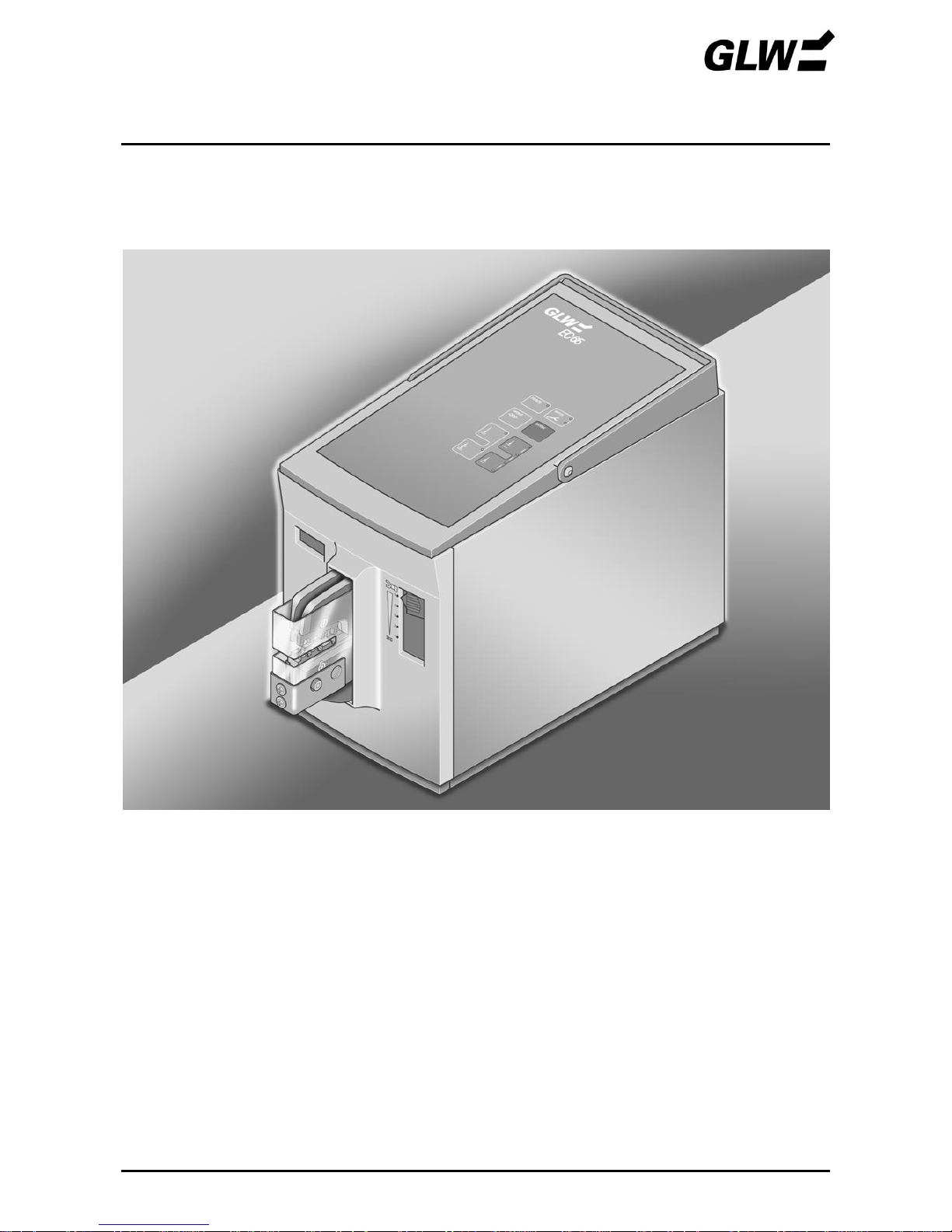
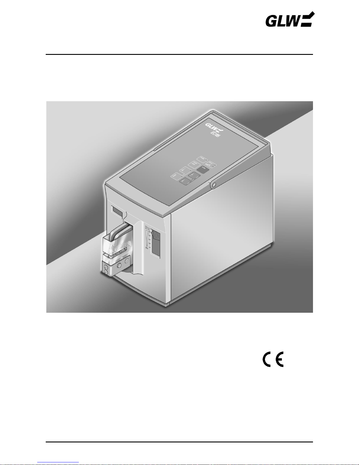
EC 65
DE Betriebsanleitung Electro Crimper EC 65
EN Operating Manual Electro Crimper EC 65
FR Mode d´emploi Sertisseuse électrique EC 65
Ausgabedatum /Date of issue/ Date d'édition: 08/2016

EC 65
EC 65
Betriebsanleitung
Elektrocrimper EC 65
Ausgabedatum: 08/2016
Für künftige Verwendung aufbewahren!

INHALT EC 65
12/09
Sicherheit
1 - 3
Grundlegende Hinweise
1
Symbole
1
Gefährlichkeit der Maschine
1
Bestimmungsgemäße Verwendung
2
Gefahrenquellen
2
Arbeitsplätze
2
Schutzeinrichtungen
2
Zugelassene Bediener
3
Gewährleistung
3
Beschreibung
4 - 7
Lieferumfang
4
Verwendung
4
Crimpgesenke
4
Bedienteile – Übersicht
5
Bedienteile - Funktion
6
Inbetriebnahme
8 - 13
Bedienung
14 – 16
Crimpen in einem Schritt
14
Crimpen in zwei Schritten
15
Störungen
17 - 19
Leuchtet
17
leuchtet nicht bzw. EC 65 lässt sich nicht einschalten
19
Ersatzteile 20
Technische Daten
21
Typenschild
21
EG Konformitätserklärung
22
Zubehör
23 - 25


SICHERHEIT EC 65
12/09 1
Grundlegende Hinweise
Grundvoraussetzung für den sicherheitsgerechten Umgang und störungsfreien Betrieb des EC 65
ist die Kenntnis und Beachtung der Sicherheitshinweise.
Es geht um Ihre Sicherheit!
Die Sicherheitshinweise sind von allen Personen zu beachten, die mit dem EC 65 arbeiten.
Darüber hinaus sind die für den Einsatzort geltenden Regeln und Vorschriften, insbesonders zur
Unfallverhütung, zu beachten.
Symbole
In dieser Betriebsanleitung werden folgende Symbole verwendet:
bezeichnet eine mögliche Unfall- und Verletzungsgefahr bzw. eine mögliche
Beschädigung des EC 65.
!
bezeichnet Anwendungshinweise.
Gefährlichkeit der Maschine
Der EC 65 ist nach anerkannten sicherheitstechnischen Regeln gebaut und wurde einer
Sicherheitsprüfung und -abnahme unterzogen.
Er ist mit Schutzeinrichtungen ausgerüstet.
Dennoch drohen bei Fehlbedienung oder Missbrauch Gefahren für
Leib und Leben des Bedieners,
die Maschine.
Der EC 65 ist nur zu benutzen
für die bestimmungsgemäße Verwendung und
in sicherheitstechnisch einwandfreiem Zustand.
Alle Personen, die mit der Inbetriebnahme, Bedienung und Instandhaltung des EC 65 zu tun
haben, müssen
entsprechend qualifiziert sein und
diese Betriebsanleitung genau beachten.
SICHERHEIT EC 65
12/09 2
Bestimmungsgemäße Verwendung
Der EC 65 ist ausschließlich für Crimparbeiten bestimmt.
Dabei dürfen nur Crimpgesenke mit dazu passenden Querschnitten gemäß Firmenbeiblatt ver-
wendet werden.
Auf keinen Fall massive Metallteile o. ä. Gegenstände einführen, das Crimpgesenk würde zerstört.
Eigenmächtige Umbauten, die über das Umrüsten hinausgehen und Veränderungen am EC 65
sind aus Sicherheitsgründen verboten!
!
Die Beachtung aller Hinweise und die Einhaltung der vorgeschriebenen
Betriebsbedingungen gehören zur bestimmungsgemäßen Verwendung.
Gefahrenquellen
Der EC 65 darf nur mit aufgesteckter Schutzhaube betrieben werden.
Vor allen Arbeiten, bei denen die Schutzhaube abgenommen werden muss (z. B. Gesenkjustie-
rung), ist der Netzstecker zu ziehen. In Arbeitspausen sowie bei Nichtgebrauch ist der Netzschalter
auszuschalten.
Arbeitsplätze
Für Betrieb und Lagerung sind zu vermeiden:
feuchte oder staubige Orte,
Orte, die hoher Wärme, direkter Sonneneinstrahlung oder tiefen Temperaturen ausgesetzt sind
(Betriebsbereich: 10 °C bis 40 °C).
Keine Flüssigkeiten auf dem EC 65 verschütten.
Den EC 65 keinen starken Erschütterungen und Stößen aussetzen.
Schutzeinrichtungen
Der EC 65 wird ausgeschaltet durch
den Netzschalter (0 gedrückt, LED dunkel).
Ziehen des Netzsteckers.
Ziehen der Schutzhaube.
Die Schutzhaube ist zur Sicherheit des Bedieners aufgesteckt. Sie darf unter keinen Umständen
verändert, entfernt oder durch Umbauten umgangen werden.
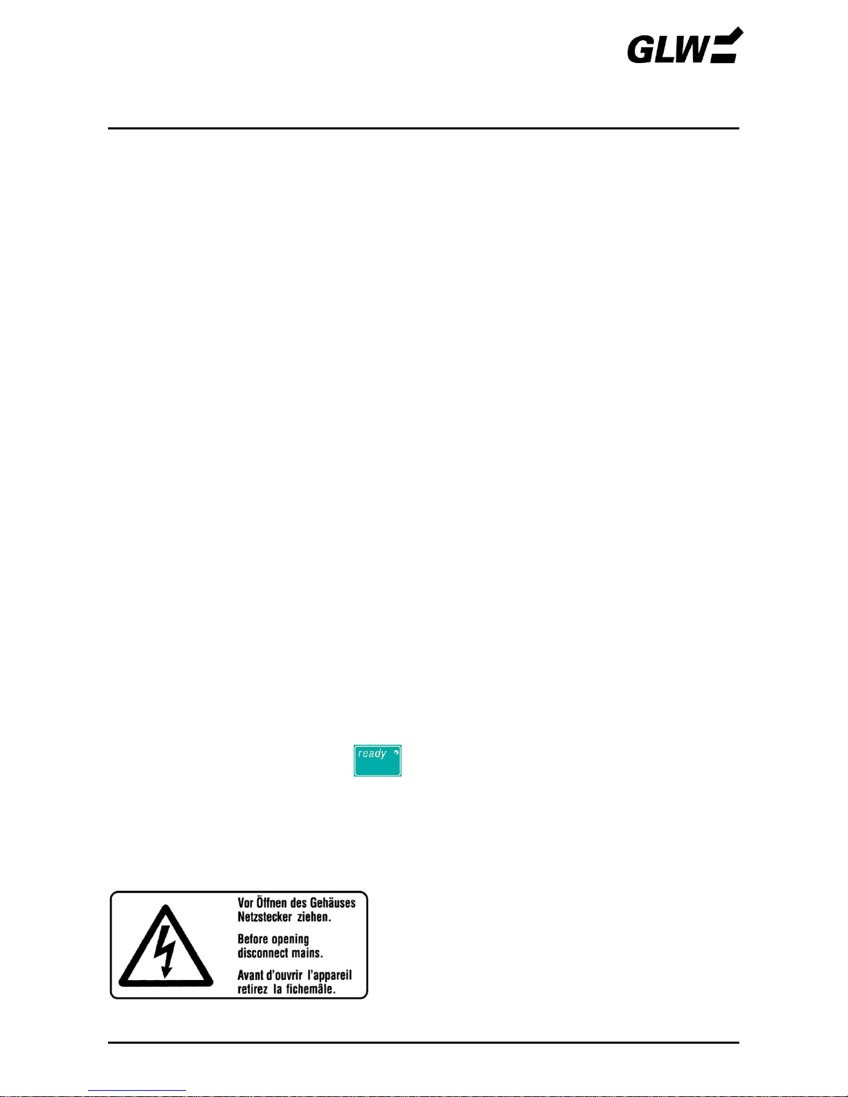
Ein Schild am Geräteboden weist auf bestehende Gefahren hin.
SICHERHEIT EC 65
12/09 3
Zugelassene Bediener
Am EC 65 dürfen nur autorisierte und eingewiesene Bediener arbeiten.
Der Bediener ist im Arbeitsbereich Dritten gegenüber verantwortlich.
Der Betreiber muss
dem Bediener die Betriebsanleitung zugänglich machen und
sich vergewissern, dass der Bediener sie gelesen und verstanden hat.
Gewährleistung
Grundsätzlich gelten unsere "Allgemeinen Verkaufs- und Lieferbedingungen". Diese stehen dem
Betreiber spätestens mit Vertragsabschluss zur Verfügung.
Gewährleistungs- und Haftungsansprüche bei Personen- und Sachschäden sind ausgeschlossen
bei Zuwiderhandlung gegen nachfolgende Punkte:
Nicht bestimmungsgemäße Verwendung des EC 65.
Unsachgemäße Arbeitsplätze.
Unsachgemäße und über die in der Betriebsanleitung beschriebene hinausgehende
Anwendung.
Eigenmächtige bauliche Veränderungen des EC 65.
Weiterbetreiben des EC 65 bei festgestellten Störungen.
Weiterbetreiben des EC 65 über 500.000 Crimpvorgänge hinaus. Nach 500.000 Crimpvor-
gängen ist ein Service durch den Hersteller durchzuführen. Der anstehende Service wird durch
LED am Bedienfeld angezeigt.
Unsachgemäß durchgeführte Gesenkmontagen/Reparaturen.
!
Nur Originalgesenke und Originalersatzteile verwenden.
BESCHREIBUNG EC 65
12/09 4
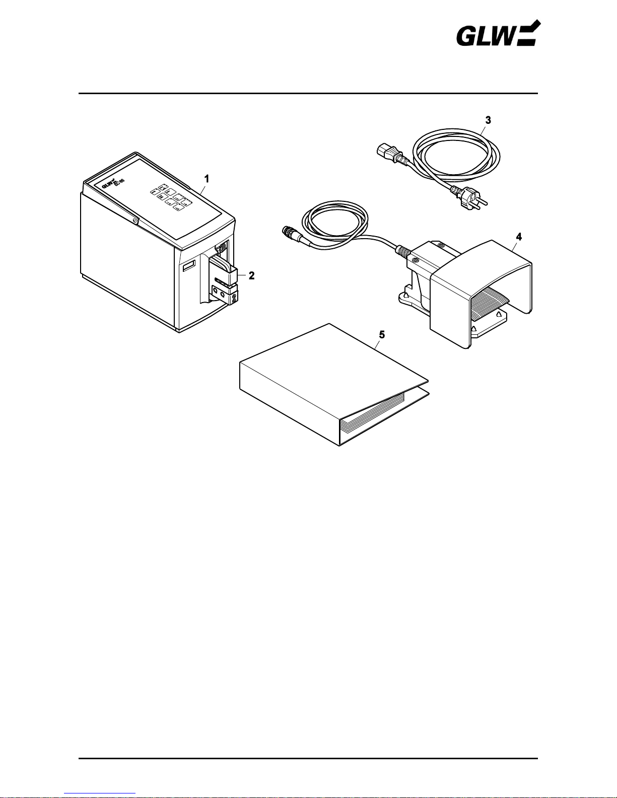
Lieferumfang
Bild 1 Lieferumfang
1
Grundgerät EC 65
4 Fußschalter
2
Schutzhaube
5
Betriebsanleitung
3
Netzkabel
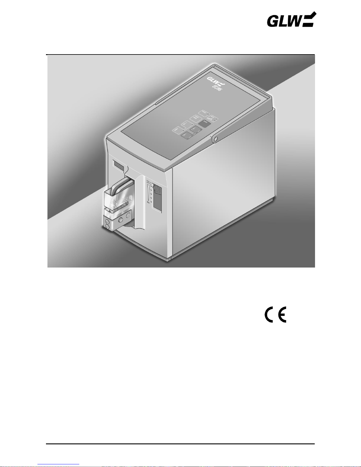
Verwendung
Der Elektrocrimper EC 65 dient zum Verpressen von Crimpkontakten.
Durch den Einsatz unterschiedlicher Crimpgesenke können Crimpkontakte verschiedenster Art in
einem großen Querschnittsbereich verarbeitet werden. Aufgrund dieser großen Bandbreite und
kurzer Taktzeiten (< 1 s) ist der EC 65 ebenso für den Einsatz in Werkstätten als auch in
komplexen Kabelkonfektionssystemen geeignet.
Crimpgesenke
Die lieferbaren Crimpgesenke sind aus den Firmenbeiblättern ersichtlich. Jedem Crimpgesenk ist
eine Schutzhaube mit passgenauem Einführungsschlitz zugeordnet.
BESCHREIBUNG EC 65
12/09 5
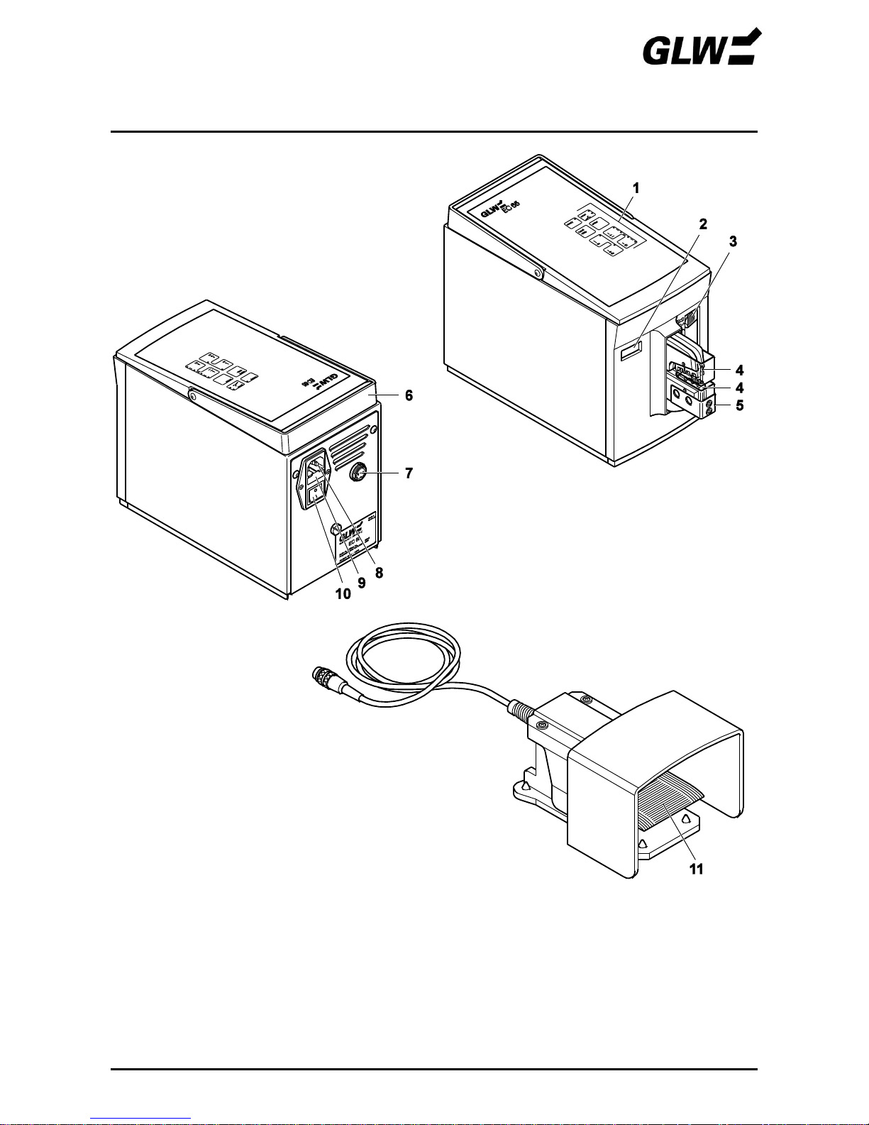
Bedienteile - Übersicht
Bild 2 Bedienteile
1
Bedienfeld
7
Anschluss Fußschalter
2
Stückzähler
8
Netzanschluss
3
Kraftbereich-Einstellschieber
9
Netzsicherungen
4
Crimpgesenk
10
Netzschalter
5
Schutzhaube
11
Fußschalter
6
Tragegriff
BESCHREIBUNG EC 65
12/09 6
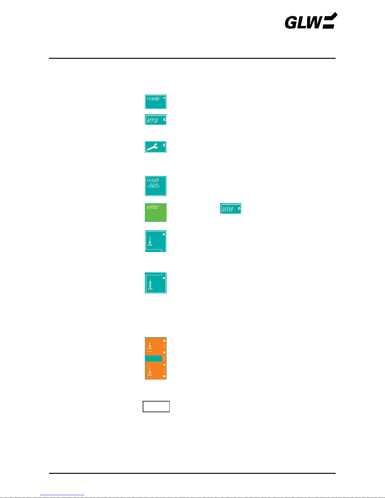
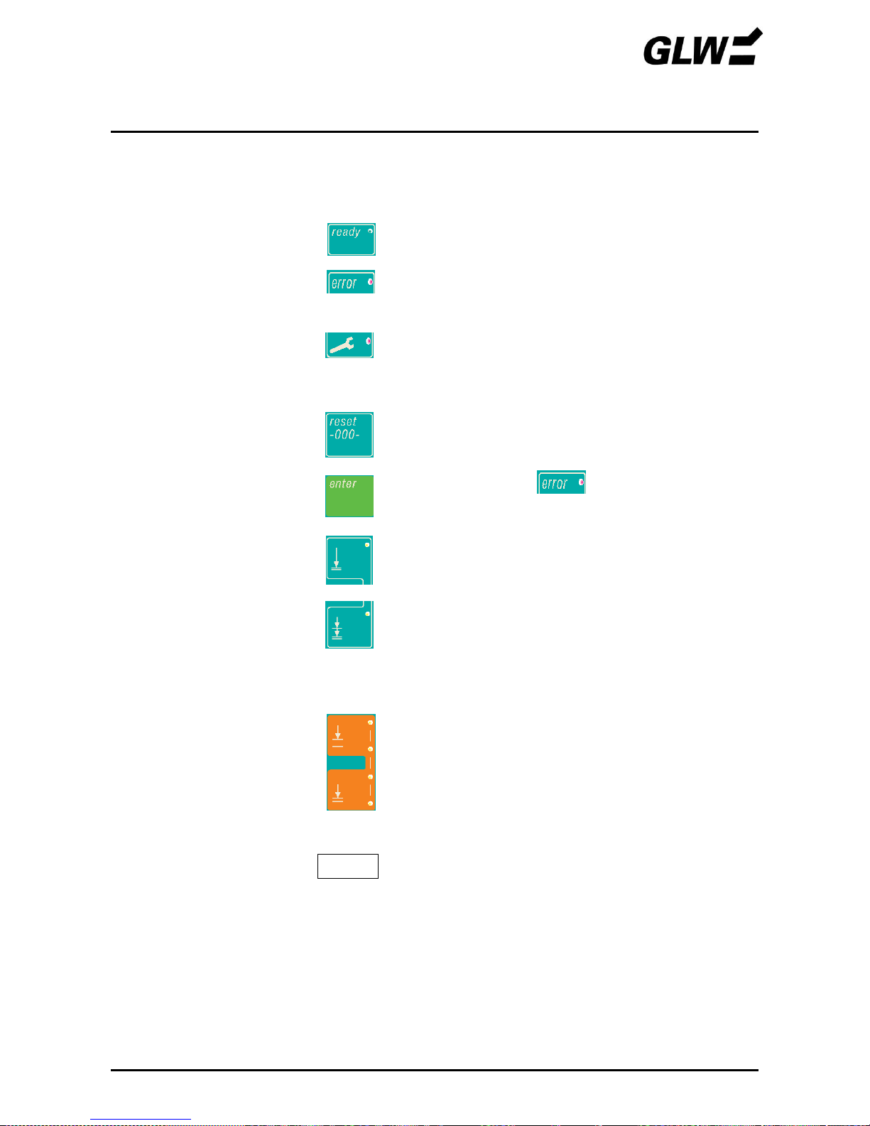
Bedienteile - Funktion
1
Bedienfeld
Dient zur Wahl von Bedienfunktionen und zur Anzeige
von Gerätezuständen
LED-ready
Zeigt die Betriebsbereitschaft an.
LED-error
Zeigt eine vorangegangene fehlerhafte Crimpung oder
eine Störung an (ein neuer Crimpvorgang lässt sich
nicht auslösen, solange die LED leuchtet).
LED-service
Zeigt einen anstehenden Service des EC 65 an (um
eine gleichbleibende Qualität der Vercrimpungen zu
gewährleisten, muss nach 500.000 Crimpungen ein
Service beim Hersteller durchgeführt werden).
Taste-reset
Setzt bei eingeschaltetem EC 65 den Zählerstand des
Stückzählers auf 0 zurück.
Taste-enter
Löscht die LED . Der EC 65 ist betriebsbereit.
Taste-Betriebsart 1
Schaltet den EC 65 in die Betriebsart 1 (LED leuchtet).
In Betriebsart 1 erfolgt der Crimpvorgang in einem
Schritt. Nach Drücken des Fußschalters wird das
Crimpgesenk vollständig geschlossen und wieder
geöffnet.
Taste-Betriebsart 2
Schaltet den EC 65 in die Betriebsart 2 (LED leuchtet).
In Betriebsart 2 erfolgt der Crimpvorgang in zwei
Schritten. Nach Drücken des Fußschalters wird der
Crimpkontakt im Crimpgesenk eingeklemmt, aber noch
nicht gecrimpt. Nun kann der Leiter in den Crimpkontakt
eingelegt werden. Nach erneutem Drücken des Fußschalters wird das Crimpgesenk vollständig
geschlossen und wieder geöffnet.
TastenÖffnungsbegrenzung
Durch Drücken der oberen (öffnen) oder unteren
(schließen) Taste kann die Öffnung des Crimpgesenkes
verändert werden. Die LEDs zeigen die Öffnung an:
4 LEDs leuchten: max. Öffnung
keine LED leuchtet: min. Öffnung
Eine Neueinstellung wird erst nach Ausführung des
nächsten Crimpvorganges wirksam.
2
Stückzähler
Der Stückzähler erfasst jeden vollendeten
Crimpvorgang. Durch Fehler abgebrochene
Crimpungen werden nicht erfasst. Der Zählerstand wird
auch bei abgeschaltetem Gerät ca. 1 Woche lang
gespeichert.
999999
BESCHREIBUNG EC 65
12/09 7
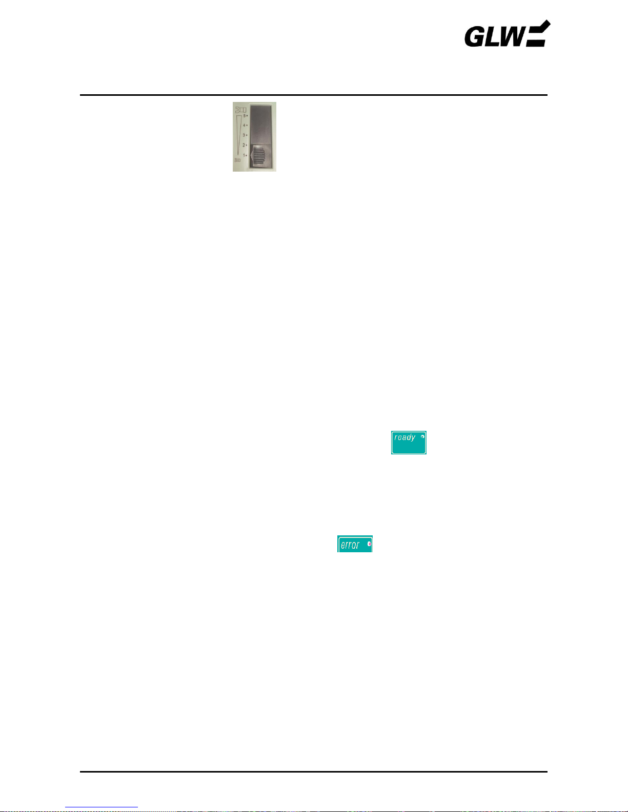
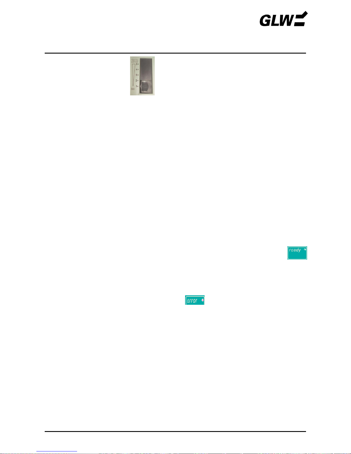
3
Kraftbereich-Einstellschieber
Mit diesem Schieber kann der Bereich eingestellt
werden, in dem das Crimpgesenk mit voller Kraft
zusammengedrückt wird. Stößt das Gesenk außerhalb
dieses Bereiches auf Widerstand, wird die Crimpzange
sofort geöffnet, um Beschädigungen an den Gesenken,
oder dem falsch eingeführten Material zu vermeiden.
Stellung 1: min. Kraftbereich
Stellung 5: max. Kraftbereich
4
Crimpgesenk
Positioniert den Crimpkontakt und verpresst diesen mit
dem Leiter.
Es besteht aus dem oberen und unteren Gesenk. Diese
können, je nach Anwendung, ausgetauscht werden.
5
Schutzhaube
Verhindert Verletzungen an Finger und Hand im
Gefahrenbereich des Crimpgesenkes.
Der EC 65 arbeitet nur bei vollständig eingesteckter
Schutzhaube..
6
Tragegriff
Dient zum Transport des EC 65.
7
Anschluss
Fußschalter
Geräteanschluss für den Fußschalter.
8
Netzanschluss
Geräteanschluss für das Netzkabel.
9
Netzsicherungen
Im Netzanschluss integrierte Feinsicherungen (2x).
10
Netzschalter
Schaltet die Stromversorgung ein (I gedrückt) oder aus
(0 gedrückt). Nach dem Einschalten leuchtet am
Bedienfeld die LED .
11
Fußschalter
Drücken des Fußschalters löst den Crimpvorgang aus.
Der Fußschalter muss solange gedrückt bleiben, bis das
Crimpgesenk vollständig geschlossen ist (Betriebsart 1)
bzw. der Crimpkontakt festgeklemmt wird (Betriebsart 2).
Leuchtet am Bedienfeld die LED , so lässt sich
der Crimpvorgang nicht auslösen.
INBETRIEBNAHME EC 65
12/09 8
1. Wahl des Aufstellungsortes
Der Aufstellungsort muss eben und waagrecht sein.
!
Die Bedingungen in Kapitel SICHERHEIT, Abschnitt Arbeitsplätze, sind zu beachten.
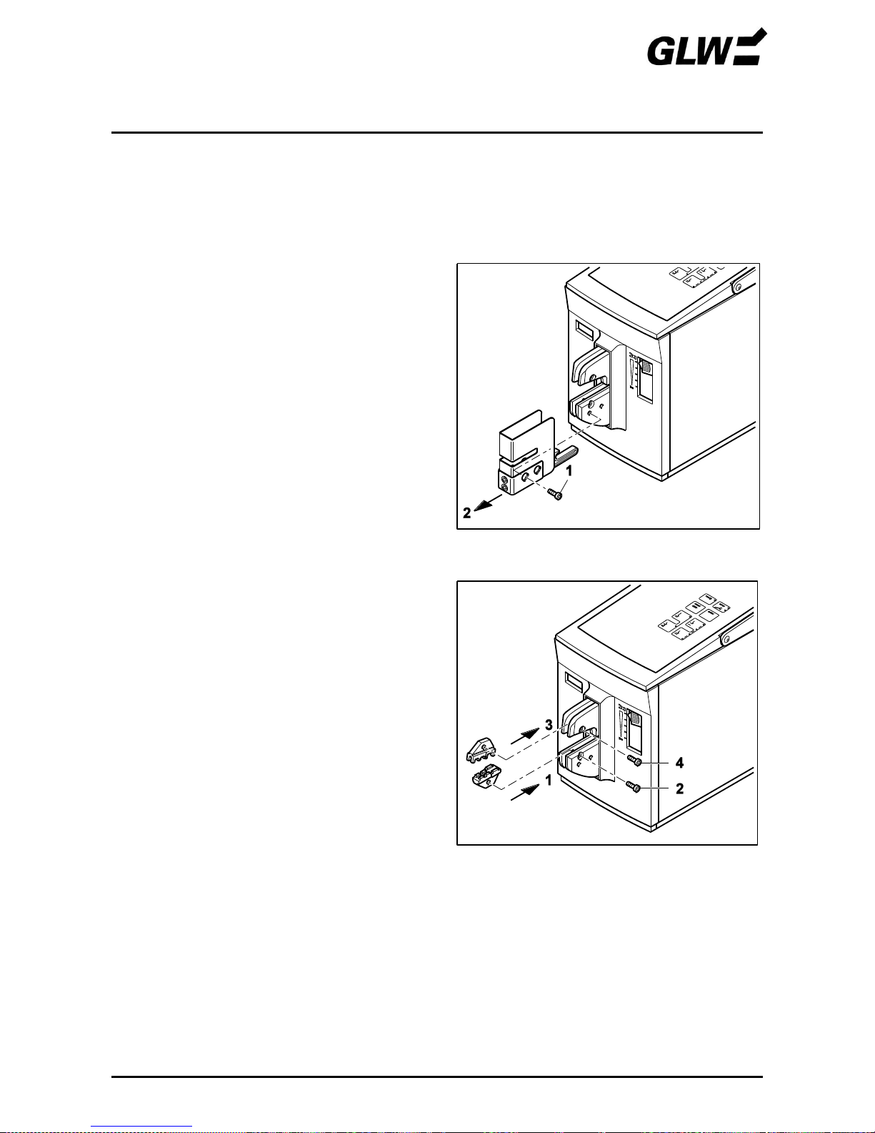
2. Schutzhaube abnehmen
Schraube (1) herausdrehen.
Schutzhaube (2) abziehen.
3. Crimpgesenk montieren
!
Einbaulage beachten:
Kleiner Querschnitt vorne.
Großer Querschnitt hinten.
Unteres Gesenk (1) einsetzen.
Schraube (2) lose anziehen.
Oberes Gesenk (3) einsetzen.
Schraube (4) lose anziehen.
Bild 3 Schutzhaube abnehmen
Bild 4 Crimpgesenk montieren
INBETRIEBNAHME EC 65
12/09 9
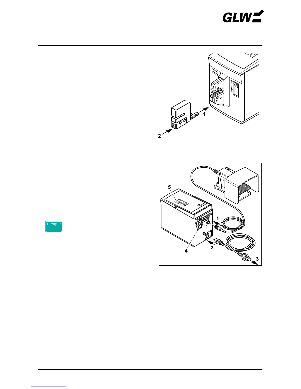
4. Schutzhaube aufstecken
• Sicherheitsdorn (1) in das untere Gesenk einsetzen und Schutzhaube (2) einschieben, bis
diese fühlbar einrastet
! Eine nicht / falsch aufgesteckte
Schutzhaube unterbricht die Stromversorgung des EC 65.
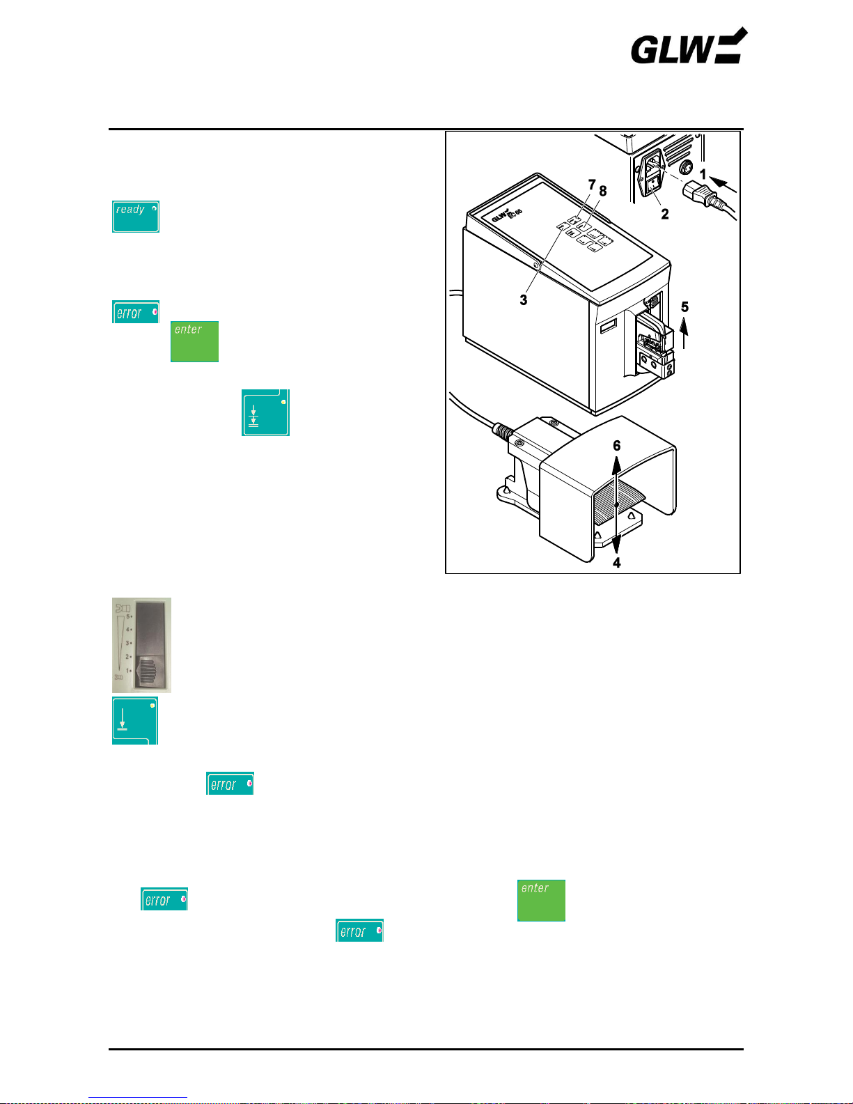
5. EC 65 anschließen / einschalten
Fußschalter (1) am Fußschalter-Anschluss
anschließen.
Netzstecker (2) am Netzanschluss und
Schukostecker (3) an Netzsteckdose
anschließen.
EC 65 mit Netzschalter (4) einschalten
(I drücken).
leuchtet (5).
Bild 5 Schutzhaube aufstecken
Bild 6 EC 65 anschließen / einschalten
INBETRIEBNAHME EC 65
12/09 10
6. Gesenke zentrieren
!
Da die Bohrungen der Gesenke etwas
Spiel zu den Befestigungsschrauben
haben, ist ein Versatz der beiden
Gesenke zueinander möglich.
Mit dem nachfolgenden Justiermodus
(Schritt 6 und 7) ist ein Zentrieren /
Justieren der Gesenke möglich.
Gleichzeitig + drücken (1).
+ blinken (2).
Kraftbereich-Einstellschieber (3) in Stellung 1
schieben.
Fußschalter (4) drücken und gedrückt halten.
Das Crimpgesenk (5) schließt langsam, bis es
auf Widerstand stößt und zentriert sich.
Fußschalter (6) loslassen.
!
Wird der Fußschalter losgelassen
bevor das Crimpgesenk geschlossen
ist, so öffnet dieses automatisch, der
Justiermodus wird beendet und
leuchtet.
Bild 7 Gesenke zentrieren
INBETRIEBNAHME EC 65
12/09 11
7. Gesenke justieren
Schutzhaube muss gezogen werden,
Netzstecker ziehen!
EC 65 mit Netzschalter (1) ausschalten
(0 drücken).
Netzstecker (2) ziehen.
Schutzhaube (3) abziehen.
Zentrierung der Gesenke prüfen, evtl. nach-
justieren (4).
Schrauben (5) festziehen.
Schutzhaube (6) aufstecken und Schraube (7)
festziehen
Bild 8 Gesenke justieren
INBETRIEBNAHME EC 65
12/09 12
8. Betriebsbereitschaft herstellen
Netzstecker (1) anschließen.
Netzschalter (2) einschalten (I drücken).
leuchtet (3).
Fußschalter (4) drücken.
Crimpgesenk (5) öffnet automatisch, Fußschalter
(6) kann losgelassen werden.
leuchtet (7).
drücken (8).
Betriebsbereitschaft ist hergestellt.
!
Betriebsart 2 ist eingestellt.
Vor jeweiliger Anwendung Betriebsart
prüfen.
9. Optimalen Kraftbereich einstellen
Kraftbereich-Einstellschieber in Stellung 1 schieben.
Betriebsart 1 einstellen.
Crimpvorgang ohne eingelegten Crimpkontakt durch Drücken des Fußschalters durchführen.
Falls hierbei leuchtet, Justierung der Gesenke prüfen (siehe Schritte 6 und 7).
Crimpvorgang mit eingelegtem Leiter und Crimpkontakt durchführen.
!
Auf richtigen Querschnitt achten.
Falls leuchtet, Schieber eine Raststellung hochschieben und drücken.
Vorgang wiederholen, bis nicht mehr leuchtet.
Um evtl. Materialtoleranzen auszugleichen, Einstellschieber noch eine Rastung nach oben
schieben.
Bild 9 Betriebsbereitschaft herstellen

INBETRIEBNAHME EC 65
12/09 13
10. Optimalen Öffnungsweg einstellen
Obere Taste drücken, bis alle 4 LEDs leuchten. Der maximale Öffnungsweg ist ein
gestellt.
Crimpvorgang durchführen.
!
Einstellungsänderungen wirken sich erst nach Ausführung des nächsten Crimpvorganges
aus.
Ist der Öffnungsweg zu groß, untere Taste drücken (3 LEDs leuchten) und neuen Crimpvorgang
durchführen.
Vorgang wiederholen, bis optimaler Öffnungsweg eingestellt ist.
BEDIENUNG EC 65
12/09 14
Crimpen in einem Schritt
1. Betriebsart 1 einstellen
EC 65 mit Netzschalter (1) einschalten
(I drücken).
leuchtet (2).
Betriebsart 1 einstellen (3).
Bei Bedarf Stückzähler (4) ablesen und mit
auf 0 rücksetzen (5)
2. Crimpkontakt crimpen
Crimpkontakt (1) auf unterem Gesenk zentrieren.
Leiter (2) in Crimpkontakt einlegen.
!
Auf richtigen Querschnitt gemäß
Firmenbeiblatt achten.
Fußschalter (3) drücken, bis das Crimpgesenk
vollständig geschlossen ist (4).
Crimpgesenk (5) öffnet automatisch, Fußschalter
(6) kann losgelassen werden.
Crimpkontakt mit gecrimpten Leiter entnehmen
(7).
!
Bei fehlerhafter Crimpung leuchtet
. Kapitel STÖRUNGEN zu Rate
ziehen.
3. Außer Betrieb setzen
Ggf. Stückzähler (1) ablesen.
EC 65 mit Netzschalter (2) ausschalten
(0 drücken).
Bild 10 Betriebsart 1 einstellen
Bild 11 Crimpkontakt crimpen
Bild 12 Außer Betrieb setzen
BEDIENUNG EC 65
12/09 15
Crimpen in zwei Schritten
1. Betriebsart 2 einstellen
EC 65 mit Netzschalter (1) einschalten
(I drücken).
leuchtet (2).
Betriebsart 2 einstellen (3).
Bei Bedarf Stückzähler (4) ablesen und mit
auf 0 rücksetzen (5)
2. Crimpkontakt festklemmen
Crimpkontakt (1) auf unterem Gesenk zentrieren.
!
Auf richtigen Querschnitt gemäß
Firmenbeiblatt achten.
Fußschalter (2) drücken, bis der Crimpkontakt
festgeklemmt ist (3).
Fußschalter (4) loslassen.
Bild 13 Betriebsart 2 einstellen
Bild 14 Crimpkontakt festklemmen
BEDIENUNG EC 65
12/09 16
3. Crimpkontakt crimpen
Leiter (1) in Crimpkontakt einlegen.
Fußschalter (2) drücken, bis das Crimpgesenk
vollständig geschlossen ist (3).
Crimpgesenk (4) öffnet automatisch, Fußschalter
(5) kann losgelassen werden.
Crimpkontakt mit gecrimpten Leiter entnehmen
(6).
!
Bei fehlerhafter Crimpung leuchtet
. Kapitel STÖRUNGEN zu Rate
ziehen.
4. Außer Betrieb setzen
Ggf. Stückzähler (1) ablesen.
EC 65 mit Netzschalter (2) ausschalten
(0 drücken).
Bild 15 Crimpkontakt crimpen
Bild 16 Außer Betrieb setzen
STÖRUNGEN EC 65
12/09 17
leuchtet
Für diese Störung gibt es folgende Ursachen:
1. Fußschalter zu früh losgelassen
Bei vorzeitigem Loslassen des Fußschalters öffnet das Crimpgesenk sofort bis zur Ausgangs-
stellung.
drücken.
erlischt.
Crimpvorgang wiederholen.
2. Falsch gewählter Querschnitt
Bei Einlegen eines zu großen Crimpkontaktes oder sonstigen ungeeigneten Gegenständen wird
der Crimpvorgang wegen Überlastung abgebrochen und das Crimpgesenk öffnet sofort bis zur
Ausgangsstellung.
drücken.
erlischt.
Crimpvorgang mit richtigem Querschnitt gemäß Firmenbeiblatt wiederholen.
3. Falsch eingestellter Kraftbereich
Überschreitet der beim Crimpvorgang erreichte Widerstand den am Kraftbereich-Einstellschieber
eingestellten Bereich, so öffnet das Crimpgesenk sofort bis zur Ausgangsstellung.
Kraftbereich-Einstellschieber eine Raststellung nach oben schieben.
drücken.
erlischt.
Crimpvorgang wiederholen, bis Kraftbereich optimal eingestellt ist.
STÖRUNGEN EC 65
12/09 18
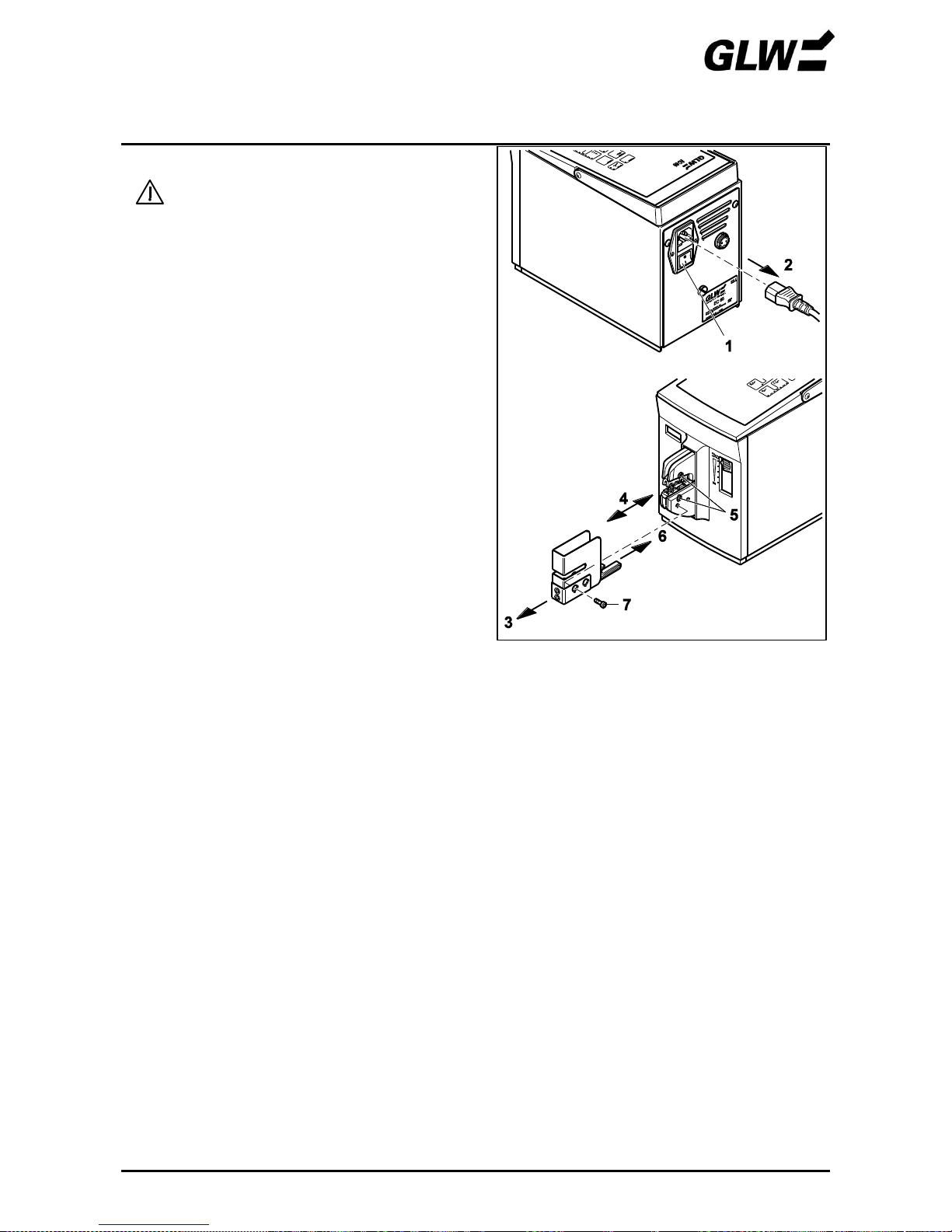
4. Gesenke nicht richtig justiert
Schutzhaube muss gezogen werden,
Netzstecker ziehen!
• EC 65 mit Netzschalter (1) ausschalten
(0 drücken).
• Netzstecker (2) ziehen.
Schraube (3) herausdrehen.
Schutzhaube (4) abziehen.
Schrauben (5) lösen.
Schritte 4 bis 10 der INBETRIEBNAHME
durchführen.
Bild 17 Gesenke lösen
STÖRUNGEN EC 65
12/09 19
leuchtet nicht bzw. EC 65 lässt sich nicht einschalten
Für diese Störung gibt es folgende Ursachen:
1. Kein Netzanschluss
Prüfen Sie, ob der Netzstecker am Netzanschluss des EC 65 und der Schukostecker an der
Netzsteckdose angeschlossen sind.
Vergewissern Sie sich, dass die Stromversorgung an der Netzsteckdose i. O. ist.
2. Netzsicherung defekt
Netzanschluss muss geöffnet werden,
Netzstecker ziehen!
EC 65 mit Netzschalter (1) ausschalten
(0 drücken).
Netzstecker (2) ziehen.
Sicherungshalter (3) herausziehen.
Netzsicherungen (4) prüfen.
Defekte Netzsicherung ersetzen (Artikel-Nr siehe
Kapitel ERSATZTEILE).
Sicherungshalter einschieben.
!
Sicherungshalter muss einrasten.
Bild 18 Netzsicherung prüfen
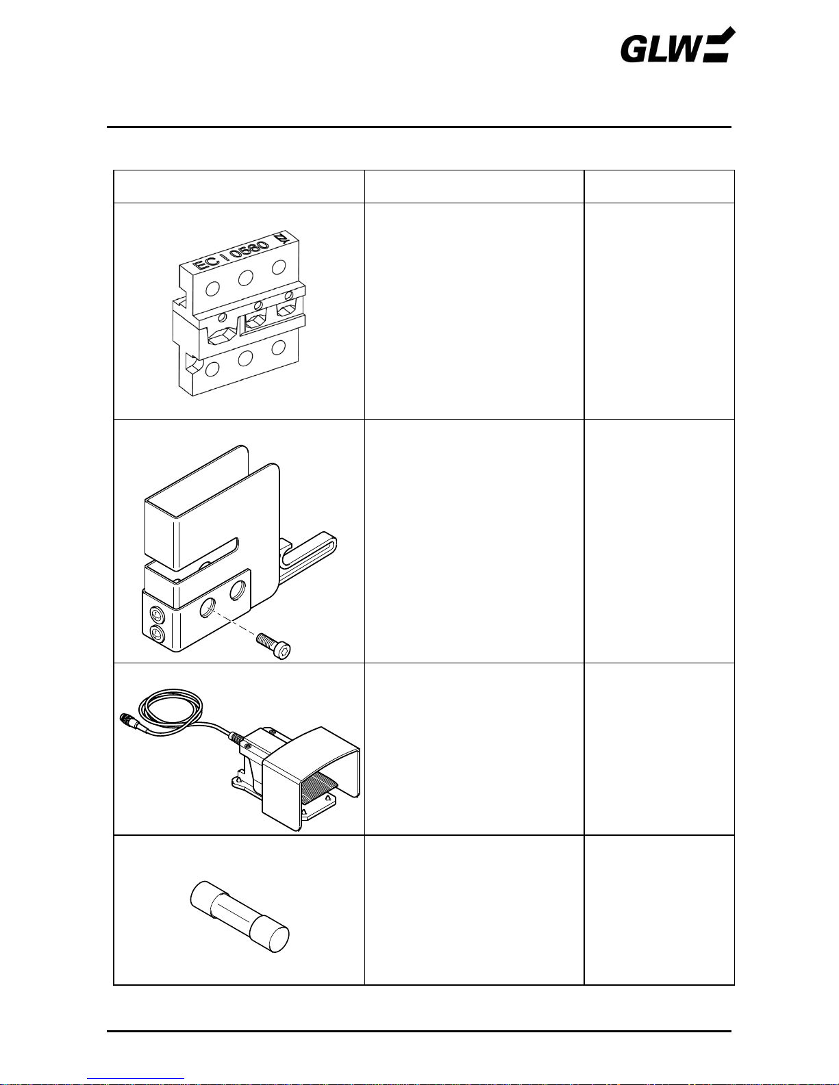
ERSATZTEILE EC 65
08/16 20
Nachfolgend aufgeführte Ersatzteile können unter Angabe der zugehörigen Artikel-Nr nachbestellt
werden.
Teil
Artikel-Nr
Liefermenge
Gesenke
Weitere Crimp - Gesenke siehe
Seite 23 – 24 und
www.glw.de/Crimpen
Schutzhaube
Weitere Schutzhauben siehe
Seite 23 – 24 und
www.glw.de/Crimpen
Fußschalter
005058
1 Stück
Netzsicherung T1,25A
001805
2 Stück
TECHNISCHE DATEN EC 65
08/16 21
Netzanschluss ............................................................................................................. 230 V / 50 Hz
Leistungsaufnahme ................................................................................................................ 160 VA
Max. Presskraft ........................................................................................................................ 10 kN
Presszeit ................................................................................................................................... < 1 s
Stückzähler ............................................................................... 6-stellige LCD-Anzeige, rücksetzbar
Maße (B x H x T)............................................................................................... 140 x 222 x 320 mm
Gewicht Grundgerät ................................ ..................................................................................10 kg
Gewicht Fußschalter ................................................................................................................1,2 kg
Emissionsschalldruckpegel LpA ....................................................................................... < 70 dB (A)
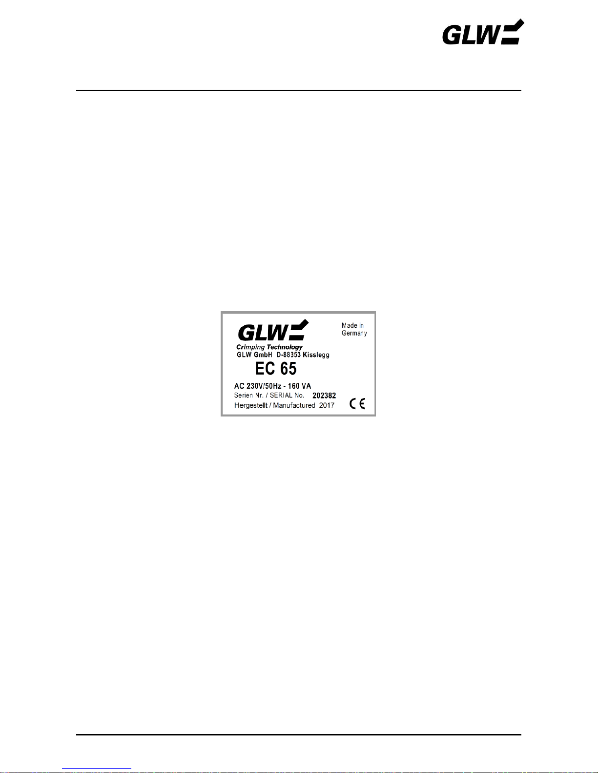
Typenschild
Herstellerland
Seriennummer
Baujahr
Leistungsaufnahme
Hersteller
Herstelleradresse
Maschinentyp
Netzanschluss
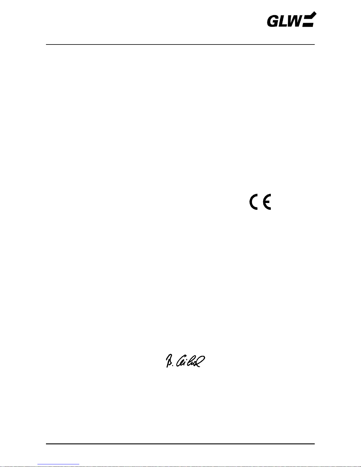
EG Konformitätserklärung EC 6 C 65
03/16 22
Hersteller: GLW GmbH
Anschrift: Steinbeisstraße 2
88353 Kisslegg
Germany
Hiermit erklären wir, dass die nachfolgend bezeichnete Maschine aufgrund ihrer Konzipierung und
Bauart sowie in der von uns in Verkehr gebrachten Ausrüstung den einschlägigen grundlegenden
Sicherheits- und Gesundheitsanforderungen der EG-Maschinenrichtlinie entspricht. Bei einer nicht
mit uns abgestimmten Änderung der Maschine verliert diese Erklärung ihre Gültigkeit.
Bezeichnung des
Betriebsmittels: Crimpautomat für Crimpkontakte
Maschinentyp: EC 65
EC 65 US (115 V)
Einschlägige EG-Maschinenrichtlinie 2006/42/EG
EG-Richtlinien: EG-Niederspannungsrichtlinie 2006/95/EG
EG-Richtlinie Elektromagnetische Verträglichkeit 2004/108/EG
Angewandte DIN EN ISO 12100-1 und -2:2004
harmonisierte DIN EN ISO 13857:2008
Normen DIN EN 349:2008
DIN EN 60204-1:2006
DIN EN 50081-1:1993
DIN EN 50082-2:1994
Ort, Datum Kisslegg, 16.03.2016
Rechtsverbindliche Unterschrift:
Angaben zum Unterzeichner: Bruno Weiland
Als Dokumentationsverantwortlicher wurde bestellt: Bruno Weiland
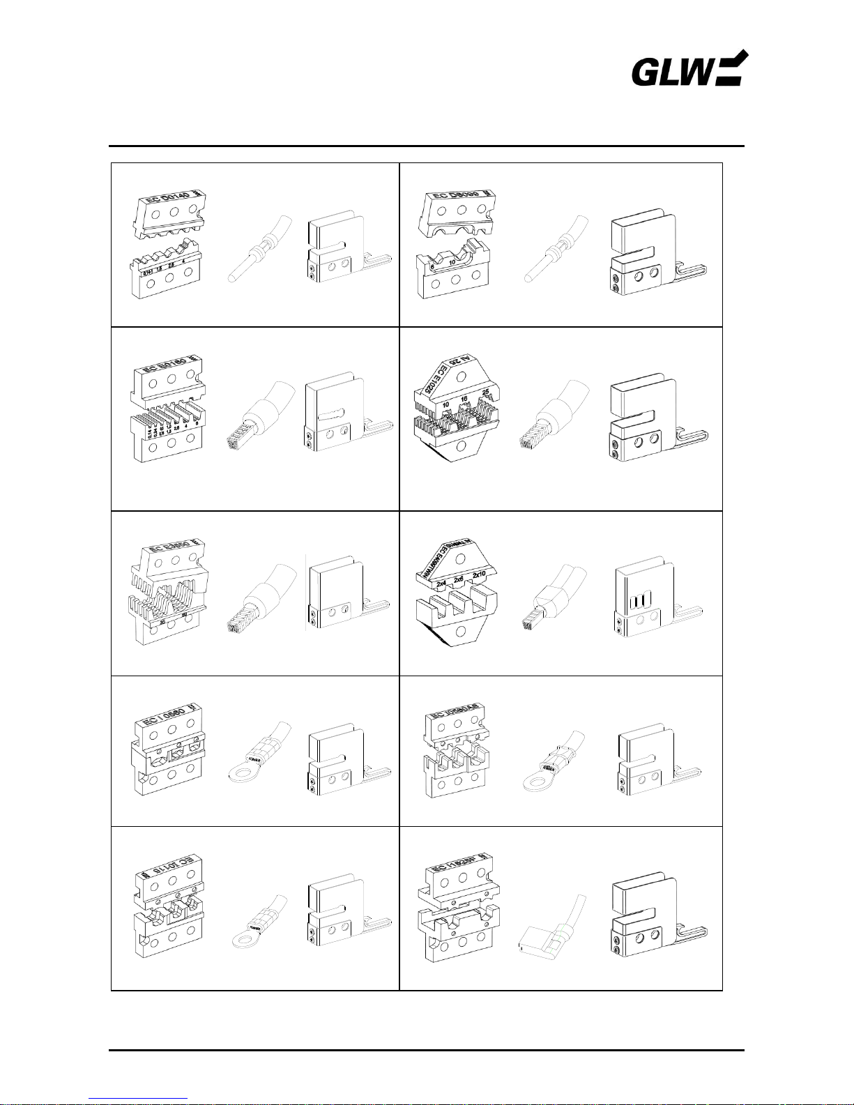
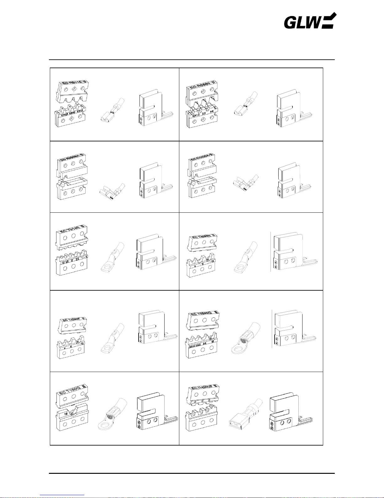
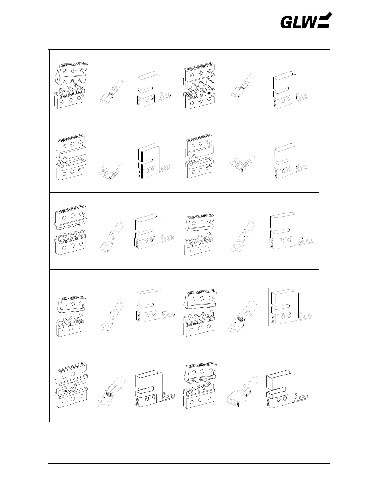
ZUBEHÖR EC 65
Crimpgesenke, Kontakte und Schutzhauben für unisolierte Flachsteckverbindung
08/16 23
EC D0140
EC PC06
EC D6099
EC PC 04.1
0,14-1,0 / 1,5 / 2,5 / 4 mm²
6 / 10 mm²
EC E0160
EC PC05
EC E1025
EC PC01
0,08-0,14/ 0,25-0,34/ 0,5-0,75/ 1-1,5/ 2,5 / 4 / 6
mm²
10 / 16 / 25 mm²
EC E3550
EC PC01
EC E4099TW
EC PC07
35 / 50 mm²
2x 4 / 2x 6 / 2x 10 mm² TWIN
EC I0560
EC PC06
EC I0560AS
EC PC06
0,5 – 6 mm²
0,5 – 6 mm² asy.
EC I0115
EC PC06
EC I1525F
EC PC06.1
0,10 – 1,5 mm²
1,5² - 2,5 mm²
weitere Crimpgesenke unter www.glw.de/Crimpen
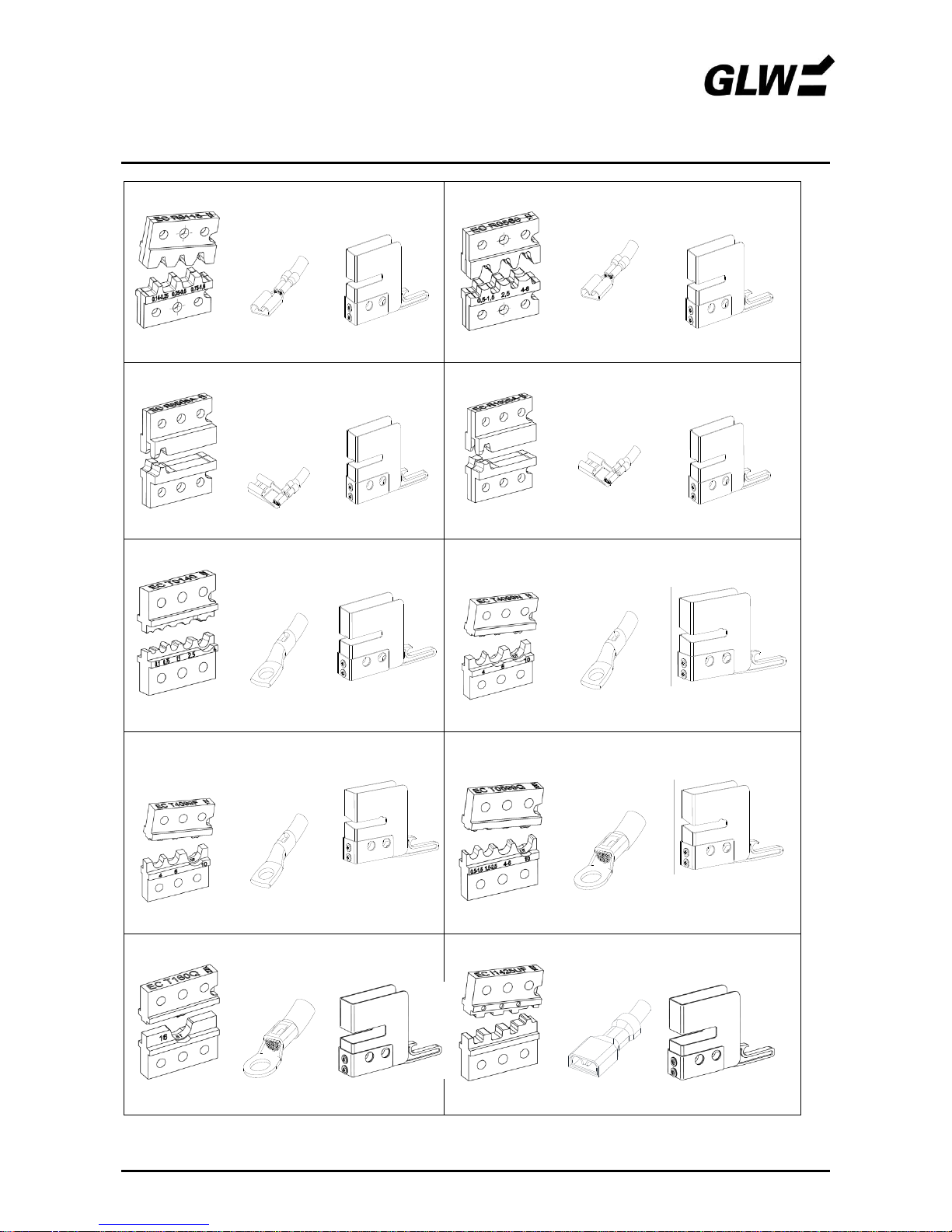
ZUBEHÖR EC 65
Crimpgesenke, Kontakte und Schutzhauben für unisolierte Flachsteckverbindung
08/16 24
EC R0115
EC PC02
EC R0560
EC PC02
0,1-0,5 / 0,5-1 / 0,5-1,5 mm²
0,5-1,5 / 2,5 / 4-6 mm²
EC R0508A
EC PC02
EC R1025A
EC PC02
0,5 – 0,75 mm²
1,0 – 2,5 mm²
EC T0140
EC PC04
EC T4099N
EC T4099E
øa/i 5/3 - 6,5/4,5 - 7/4,5
EC PC03
øa/i 5/3 - 6/4 - 8/5
0,34-0,75 /1-1,5 / 2,5 mm²
4 / 6 / 10 mm²
EC T4099P
EC T4099F
(NFC 20-130)
øa/i 5/3 - 5,5/3,8 - 8/5
EC PC03
EC T0599Q
EC PC03
øa/i 5/2,7- 5,5/3,3-
6,8/4,2
4 / 6 / 10 mm²
0,5 -1,5 / 1,5 - 2,5 / 4 - 6 / 10 mm²
EC T160Q
EC PC04.1
EC I1425UF
EC PC04.1
16 mm²
0,14-0,5 / 0,5-1,5 / 1,5-2,5 mm²
weitere Crimpgesenke siehe unter www.glw.de/Crimpen
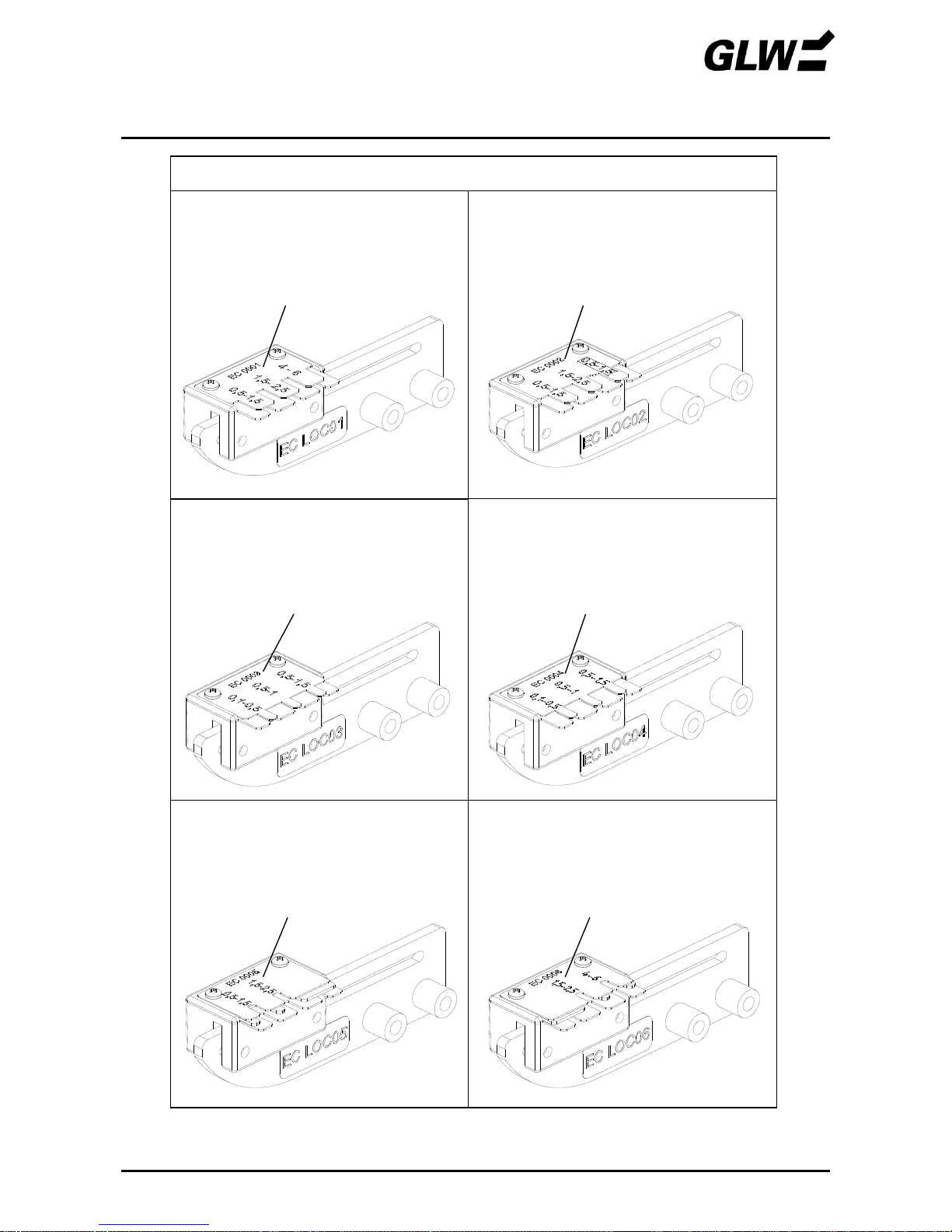
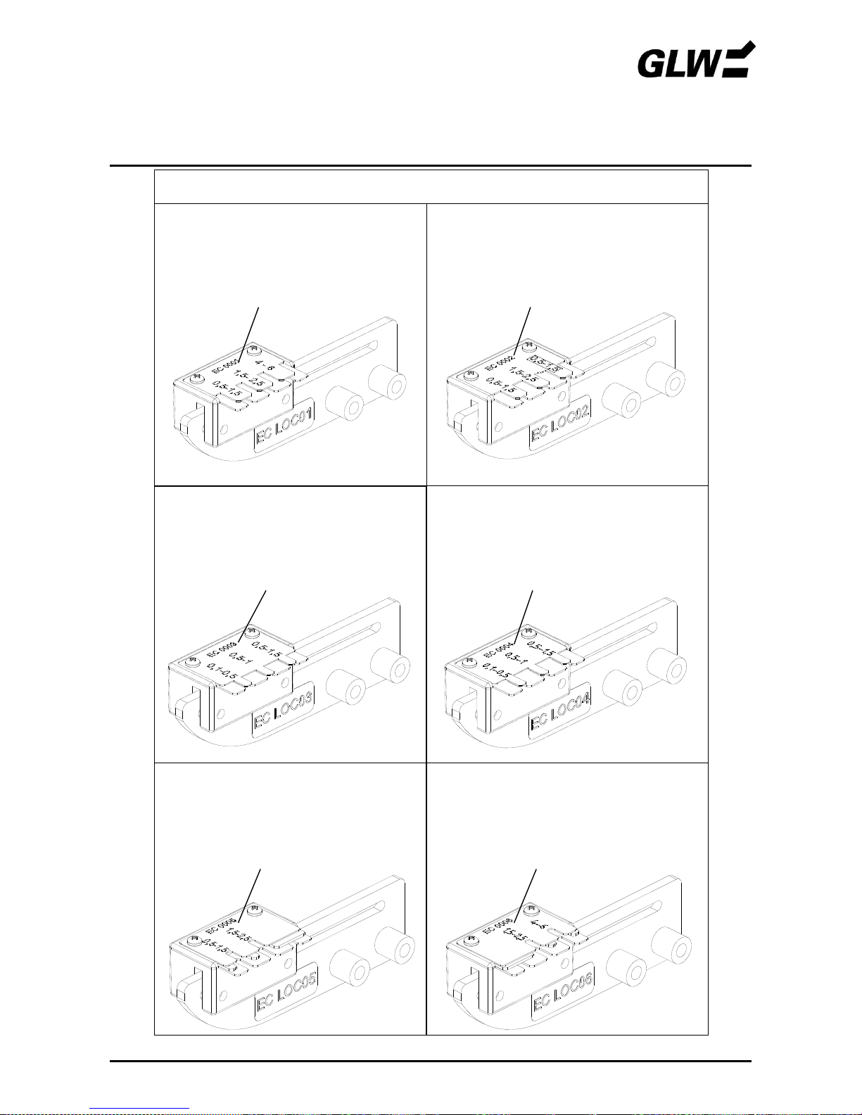
ZUBEHÖR EC 65
Locator für unisolierte Flachsteckverbindungen
08/16 25
Locator
Art.-Nr. EC LOC01 passend für:
> Flachsteckhülsen 6,3 DIN 46247
> Gesenk EC R0560
> Schutzhaube EC PC02
Ersatzteil: Positionierhilfe Art.-Nr. EC 0001
Art.-Nr. EC LOC02 passend für:
> Flachsteckhülsen 4,8 DIN 46247
> Gesenke EC R0115; EC R0560
> Schutzhaube EC PC02
Ersatzteil: Positionierhilfe Art.-Nr. EC 0002
Art.-Nr. EC LOC03 passend für:
> Flachsteckhülsen 2,8x5 DIN 4624
> Gesenke EC R0115; EC R0560
> Schutzhaube EC PC02
Ersatzteil: Positionierhilfe Art.-Nr. EC 0003
Art.-Nr. EC LOC04 passend für:
> Flachsteckhülsen 2,8x6 DIN 46247
> Gesenke EC R0115; EC R0560
> Schutzhaube EC PC02
Ersatzteil: Positionierhilfe Art.-Nr. EC 0004
Art.-Nr. EC LOC05 passend für:
> Flachstecker 6,3 DIN 46247
> Gesenke EC R0115; EC R0560
> Schutzhaube EC PC02
Ersatzteil: Positionierhilfe Art.-Nr. EC 0005
Art.-Nr. EC LOC06 passend für:
> Flachstecker 6,3 Typ HN DIN 46247
> Gesenke EC R0115; EC R0560
> Schutzhaube EC PC02
Ersatzteil: Positionierhilfe Art.-Nr. EC 0006
weitere Ausführungen unter www.glw.de/Crimpen

EC 65
GLW GmbH
Steinbeisstraße 2
88353 Kisslegg
Deutschland
Tel. (07563) 9123-0
Fax (07563) 9123-99
Das Urheberrecht an dieser Betriebsanleitung
verbleibt bei der Firma GLW.
Nachdruck, Vervielfältigung oder Übersetzung,
auch auszugsweise, sind ohne Genehmigung
nicht gestattet.
2016 GLW GmbH

EC 65
Operating Manual
Electric Crimper EC 65
Date of issue: 08/2016
Keep for future use!


Safety
1 - 3
Basic instructions
1
Symbols
1
Dangers posed by the machine
1
Correct use of the device
2
Danger sources
2
Work places
2
Protective devices
2
Authorised operators
3
Guarantee
3
Description
4 - 7
Scope of delivery
4
Use
4
Crimp dies
4
Operating components - overview
5
Operating components - function
6
Start-up
8 - 13
Operation
14 – 16
One-step crimping
14
Two-step crimping
15
Faults
17 - 19
lights
17
does not light or EC 65 cannot be switched
19
Spares
20
Technical Data
21
Rating plate
21
EC Conformity Declaration
22
Accessories
23 - 25


SAFETY EC 65
12/09 1
Basic instructions
The basic prerequisite for safe handling and trouble-free operation of the EC 65 is being familiar
with and observing the safety instructions.
It is for your own safety!
The safety instructions must be observed by all persons working with the EC 65.
In addition, the rules and regulations pertaining to the application site, particularly those concerning
the prevention of accidents, must be observed.
Symbols
The following symbols are used in this operating manual:
indicates a possible danger of accident or injury or possible damage to the EC 65.
!
indicates instructions for use.
Dangers posed by the machine
The EC 65 has been designed according to recognised technical safety rules and has been
subjected to safety testing and acceptance.
It is equipped with protection devices.
Nevertheless, in the event of operating errors or misuse there is a danger to
the life and limb of the operator,
the machine.
The EC 65 may only be used
for the purpose for which it was intended and
in a perfectly safe technical condition.
All persons involved in the start-up, operation and maintenance of the EC 65 must
be appropriately qualified and
be intimately familiar with this operating manual.

SAFETY EC 65
12/09 2
Correct use of the device
The EC 65 is designed exclusively for crimping work.
Only crimp dies with the matching cross sections according to the company supplementary
sheet may be used.
Never insert solid metal parts or similar objects; this would destroy the crimp die.
Unauthorised conversions which go beyond mere retooling and modifications to the EC 65 are
prohibited for safety reasons!
!
Correct use of the instrument includes observation of all the instructions and the
prescribed operating conditions.
Danger sources
The EC 65 may only be operated with the protective cover fitted.
The mains plug must be pulled out prior to doing any work which entails removing the protective
cover (e.g. adjusting the die). The device should be switched off at the mains switch during breaks
and when not in use.
Work places
The following places should be avoided for operation and storage:
damp or dusty places,
places exposed to high temperatures, direct sunlight or low temperatures
(operating range: 10°C to 40 °C).
Do not spill liquids onto the EC 65.
Do not expose the EC 65 to strong vibrations and impact.
Protective devices
The EC 65 is switched off by
the mains switch (0 pressed, LED dark).
pulling out the mains plug.
pulling off the protective cover.
The protective cover is fitted for the operator’s safety. It may on no account be modified, removed
or bypassed by conversions.
A sign on the bottom of the instrument warns of potential dangers.

SAFETY EC 65
12/09 3
Authorised operators
Only authorised and instructed operators may be allowed to work on the EC 65.
The operator is responsible for third persons within the working area.
The owner must
give the operator access to the operating manual and
make sure that the operator has read and understood it.
Guarantee
Our “General Terms of Sale and Delivery” apply basically. These will be available to the owner at
the latest upon signing the contract.
Guarantee and liability claims are excluded in the case of personal injury and property damage in
the event of violation of the following points:
use of the EC 65 for a purpose for which it was not intended
improper work places
improper use and use above and beyond that described in the operating manual
unauthorised constructional modifications to the EC 65
continued operation of the EC 65 after faults have been detected
continued operation of the EC 65 beyond 500,000 crimping processes. The device must be
serviced by the manufacturer after 500,000 crimping processes. A LED on the control
panel signals when the device is due for servicing.
improperly performed die assembly/repairs.
!
Only use original dies and spares.

DESCRIPTION EC 65
12/09 4
Scope of delivery
Figure 1 Scope of delivery
1
Basic device EC 65
4 Foot switch
2
Protective cover
5
Operating Manual
3
Line cord
Use
The electric crimper EC 65 is used for pressing crimp contacts.
By using different crimp dies crimp contacts of various kinds can be processed within a wide range
of cross sections. This wide range and short cycle times (< 1 s) make the EC 65 equally suitable
for use in workshops and in complex cable assembly systems.
Crimp dies
The available crimp dies are listed in the company supplementary sheets. Every crimp die is
assigned a protective cover with an exactly fitting insertion slit.

DESCRIPTION EC 65
12/09 5
Operating components - overview
Figure 2 Operating components
1
Control panel
7
Connection foot switch
2
Piece counter
8
Mains connection
3
Force range adjusting slide
9
Mains fuses
4
Crimp die
10
Power switch
5
Protective cover
11
Foot switch
6
Handle
DESCRIPTION EC 65
12/09 6
Operating components – function
1
Control panel
Serves to select operating functions and display device
states
LED-ready
indicates standby state
LED-error
indicates a preceding defective crimping or fault (a new
crimping cannot be triggered as long as the LED is
alight)
LED-service
indicates that the EC 65 is due for servicing (to
guarantee consistent quality of the crimpings, the
instrument must be serviced by the manufacturer after
500,000 crimpings).
Reset button
Sets the piece counter reading back to 0 when the
EC 65 is switched on.
Enter button
Extinguishes the LED . The EC 65 is ready.
Mode 1 button
Switches the EC 65 to mode 1 (LED lights). Crimping
takes place in one step in mode 1. The crimp die is fully
closed and reopened by pressing the foot switch.
Mode 2 button
Switches the EC 65 to mode 2 (LED lights). Crimping
takes place in two steps in mode 2. The crimp contact is
clamped in the crimp die but not crimped by pressing
the foot switch. The wire can now be inserted in the
crimp contact. The crimp die is fully closed and
reopened by pressing the foot switch a second time.
Opening limit buttons
The opening of the crimp die can be changed by
pressing the upper (open) and lower (close) button. The
LEDs indicate the opening:
4 LEDs alight: max. opening
no LEDs alight: min. opening
Resetting only becomes active after the next crimping.
2
Piece counter
The counter records every completed crimping process.
Crimpings aborted due to faults are not recorded. The
counter reading is stored for about 1 week when the
device is switched off.
999999
DESCRIPTION EC 65
12/09 7
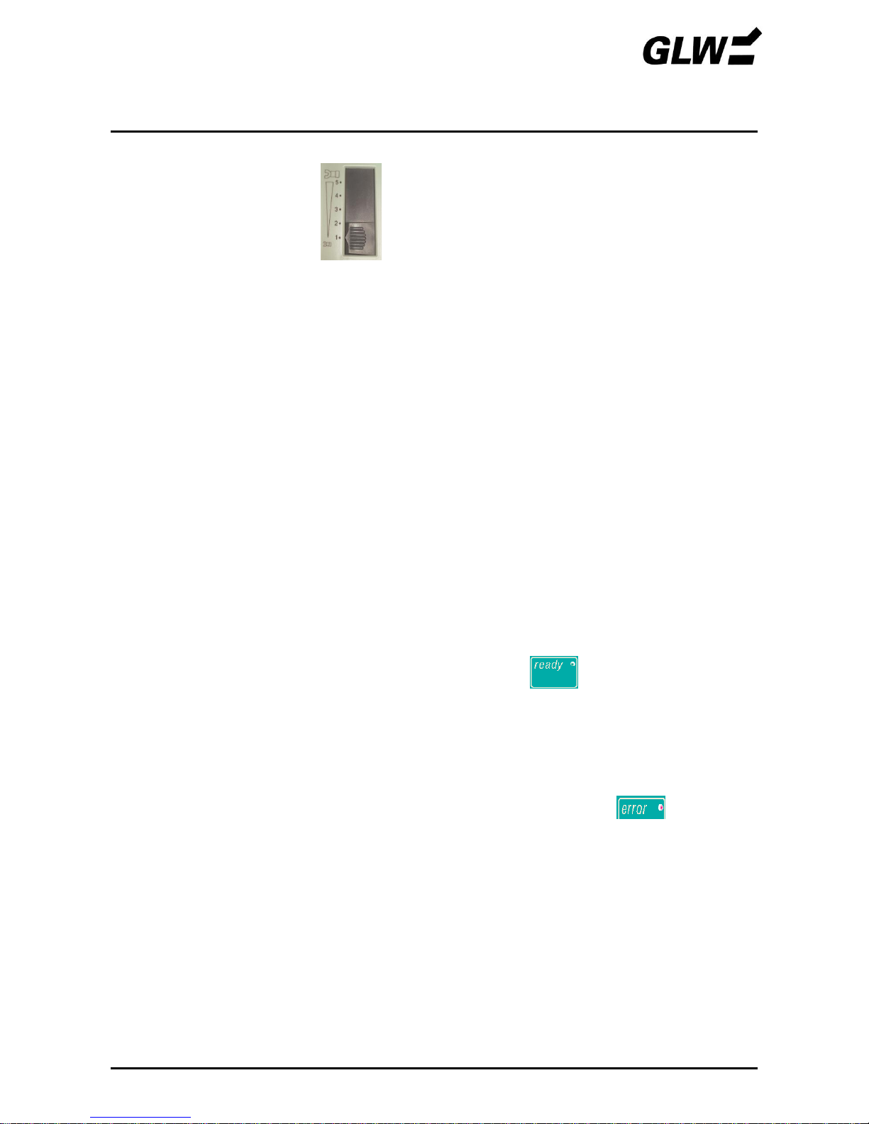
3
Force range adjusting
slide
The range in which the crimp die is pressed together
with full force can be set with this slide. If the die meets
with an obstruction outside this range, the crimping die
open immediately to avoid damage to the die or to the
falsely inserted material.
Position 1: min. force range
Position 5: max. force range
4
Crimp die
Positions the crimp contact and presses this together
with the wire.
It consists of the top and bottom die. These can be
changed depending on the application.
5
Protective cover
Prevents injury to fingers and hands in the danger area
of the crimp die.
The EC 65 only works when the protective cover is fully
inserted.
6
Handle
Serves for transporting the EC 65.
7
Connection foot
switch
Device connection for the foot switch.
8
Mains connection
Device connection for the power cable.
9
Mains fuses
Fine fuses (2x) integrated in the mains connection.
10
Power switch
Switches on the power supply (I pressed) or off
(0 pressed). The LED on the control panel
lights up after switching on.
11
Foot switch
Pressing the foot switch triggers the crimping process.
The foot switch must be kept pressed until the crimp die
is fully closed (mode 1) or the crimp contact is clamped
(mode 2).
If the LED lights up on the control panel the
crimping process cannot be triggered.

START-UP EC 65
12/09 8
1. Selecting the installation site
The installation site must be level and horizontal.
!
The conditions in the SAFETY chapter under Work Places must be observed.
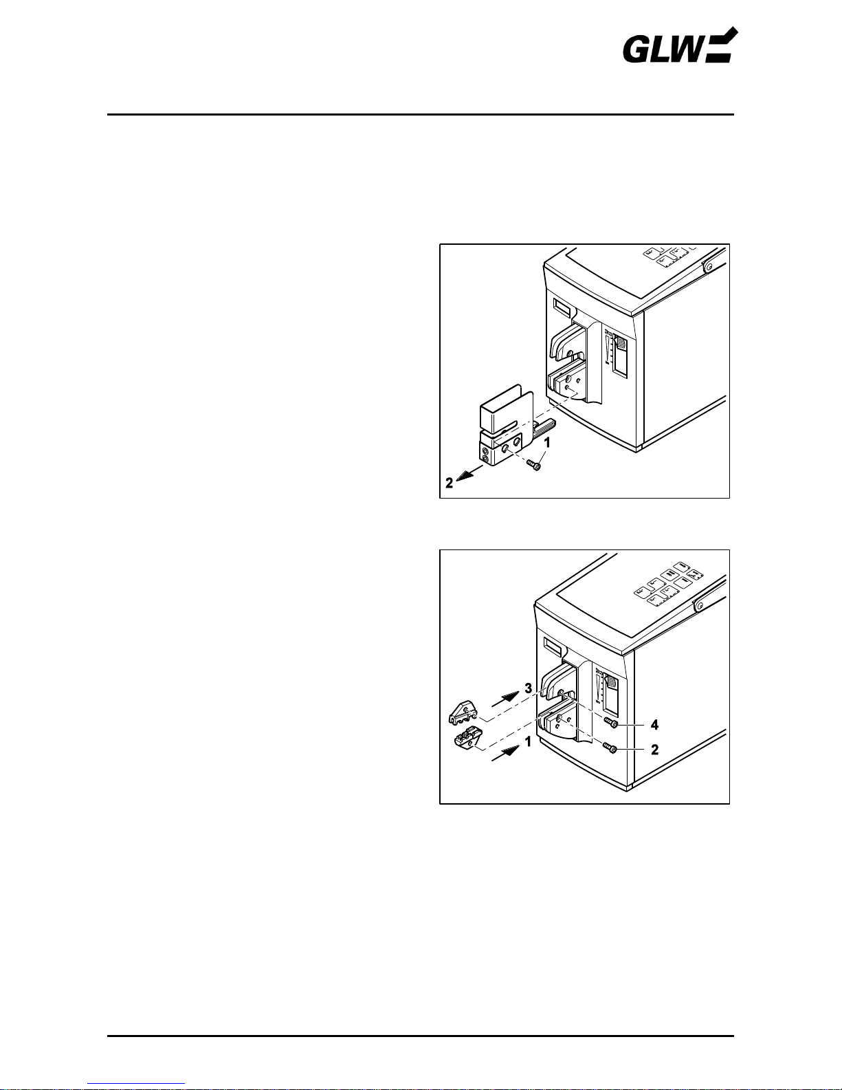
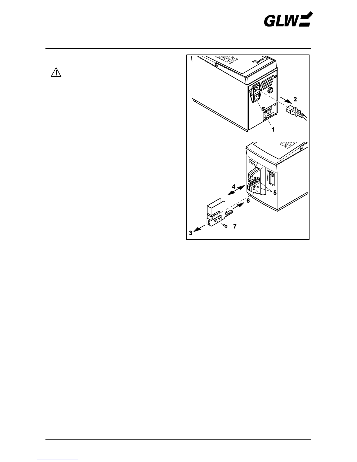
2. Removing the protective cover
Unscrew the screw (1).
Pull off the protective cover (2).
3. Mounting the crimp die
!
Note installation position:
Small cross section at front.
Large cross section at back.
Insert bottom die (1).
Screw in screw (2) loosely.
Insert top die (3).
Screw in screw (4) loosely.
Figure 3 Removing the protective cover
Figure 4 Mounting the crimp die

START-UP EC 65
12/09 9
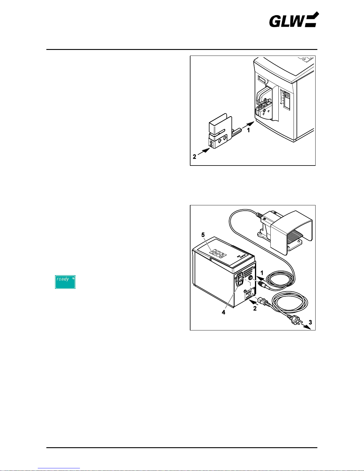
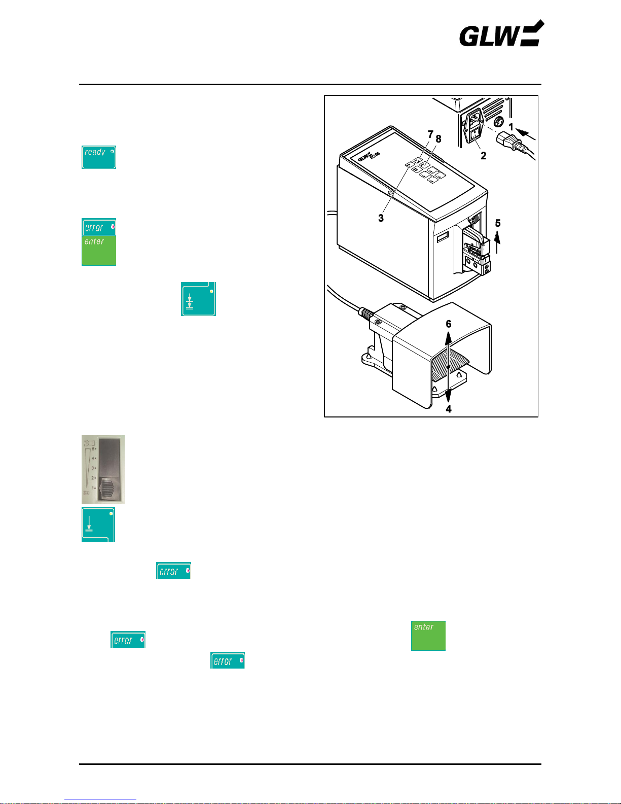
4. Mounting the protective cover
• Insert the safety pin (1) in the bottom die and
push in the protective cover (2) until you can feel it
snap in.
! The power supply to the EC 65 will be
cut off if the protective cover is not fitted
or is not fitted properly.
5. Connecting / switching on the EC 65
Connect the foot switch (1) to the foot switch
connection.
Connect the mains plug (2) on the mains
connection and the shock-proof plug (3) to the
mains socket.
Switch on the EC 65 at the mains switch (4)
(press I).
lights up (5).
Figure 5 Mounting the protective cover
Figure 6 Connecting / switching on the EC 65
START-UP EC 65
12/09 10
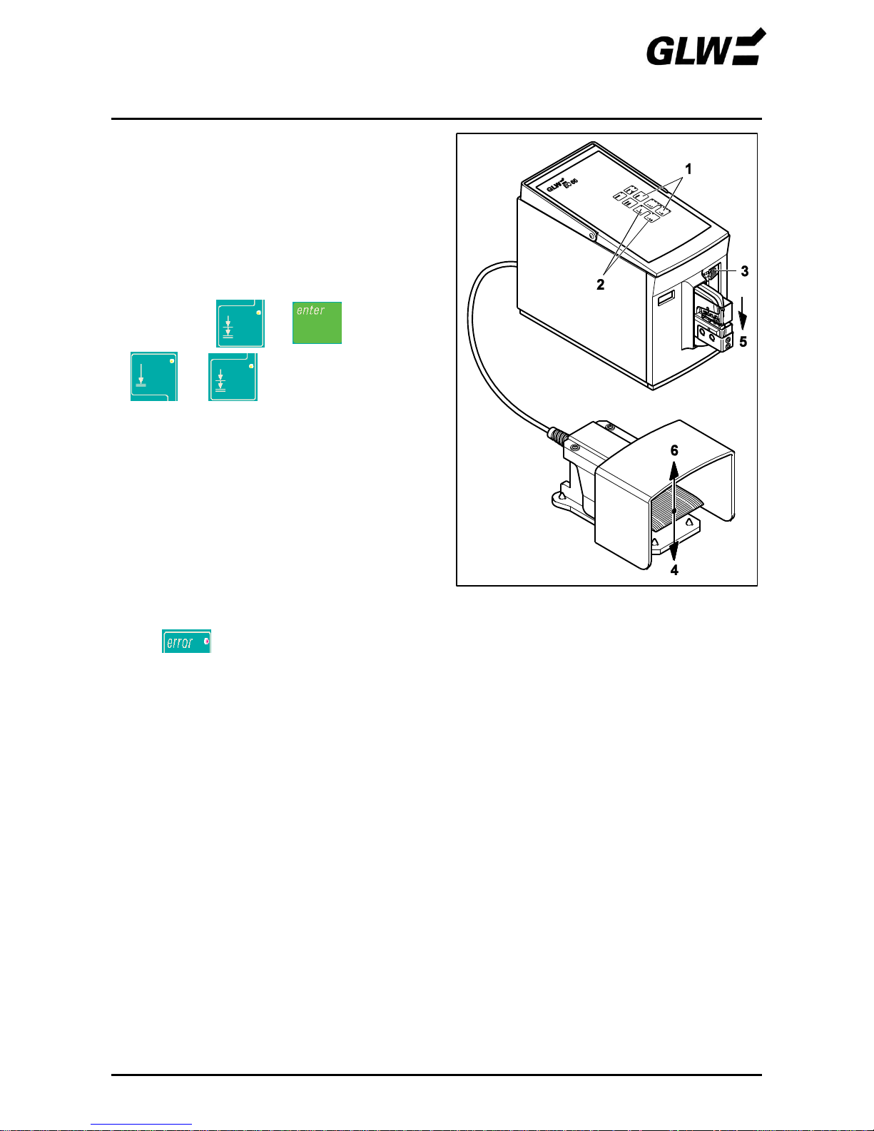
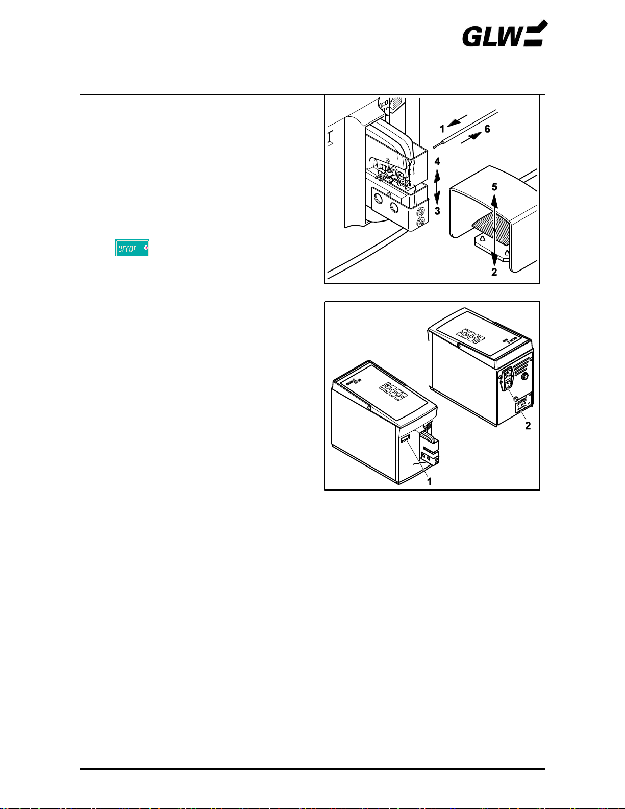
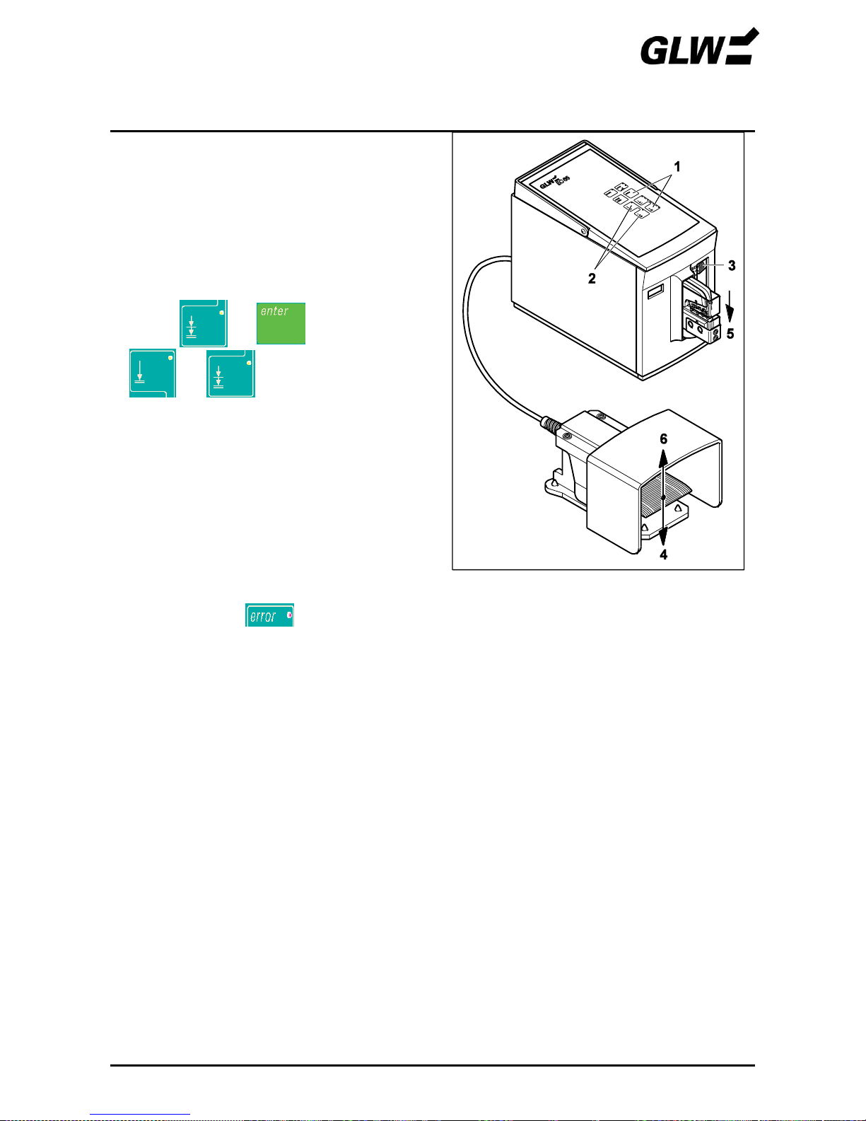
6. Centring the dies
!
Since the bores of the dies have a
slight clearance to the fastening
screws it is possible to offset the dies
to each other.
Centring / adjustment of the dies is
possible with the following adjustment
mode (steps 6 and 7).
Press + simultaneously (1).
+ flash (2).
Push force range adjusting slide (3) to
position 1.
Press the foot switch (4) and keep it pressed.
The crimp die (5) closes slowly until it meets
with a resistance and centres itself.
Release the foot switch (6).
!
If the foot switch is released before the
crimp die is closed, this opens
automatically, the adjustment mode is
ended and lights.
Figure 7 Centring the dies
START-UP EC 65
12/09 11
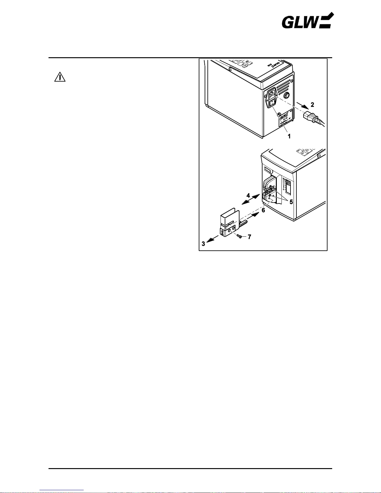
7. Adjusting the dies
The protective cover must be pulled
off, pull out the mains plug!
Switch off the EC 65 at the power switch (1) (press
0).
Pull out the mains plug (2).
Pull off the protective cover (3).
Check the centring of the dies, adjust if necessary
(4).
Tighten the screw (5).
Push on the protective cover (6) and tighten the
screw (7).
Figure 8 Adjusting the dies

START-UP EC 65
12/09 12
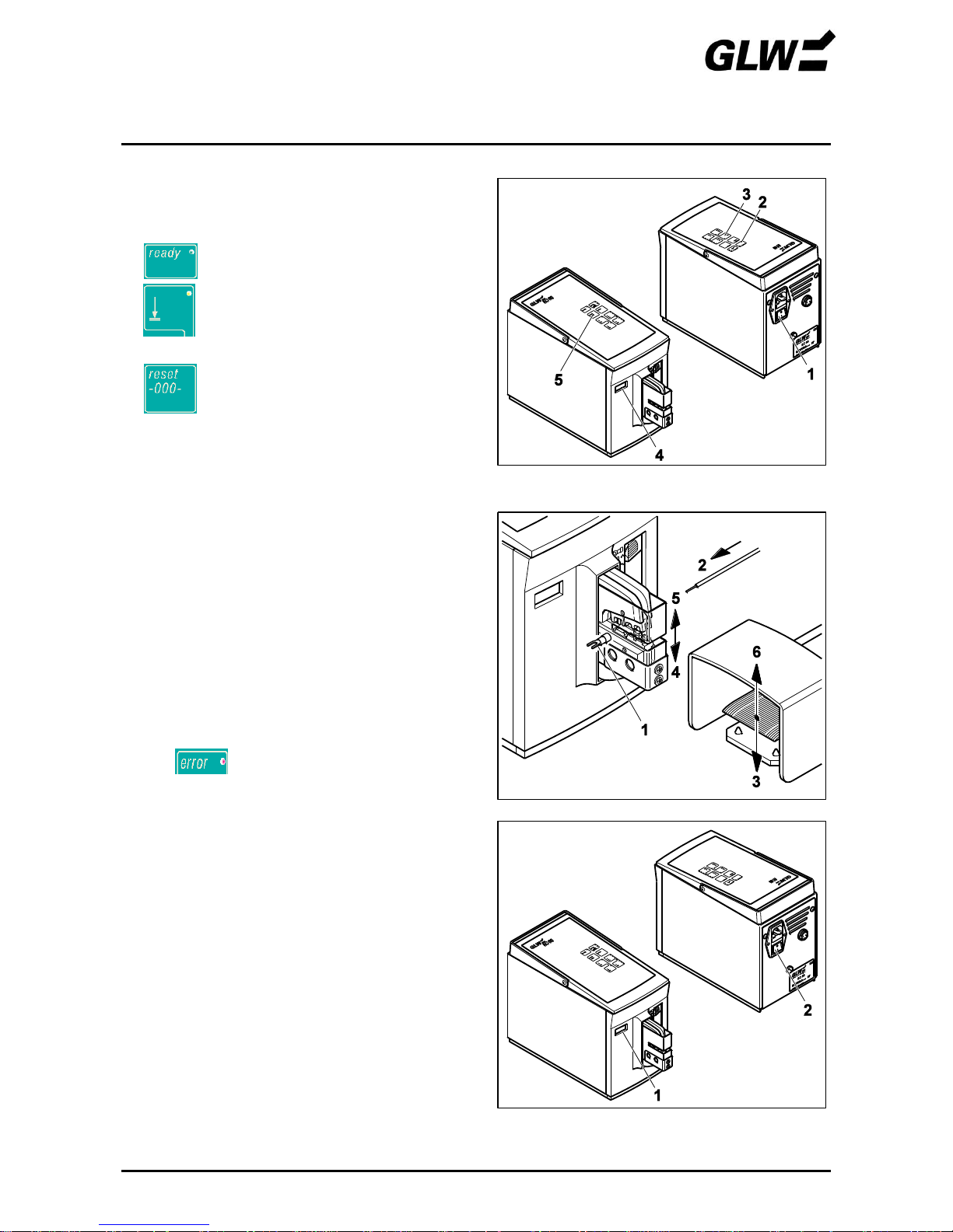
8. Getting the device ready
Connect the mains plug (1).
Switch on the power switch (2) (press I).
lights up (3).
Press the foot switch (4).
The crimp die (5) opens automatically, the foot
switch (6) can be released.
lights up (7).
Press (8).
The device is ready.
!
Mode 2 is set.
Check mode before using.
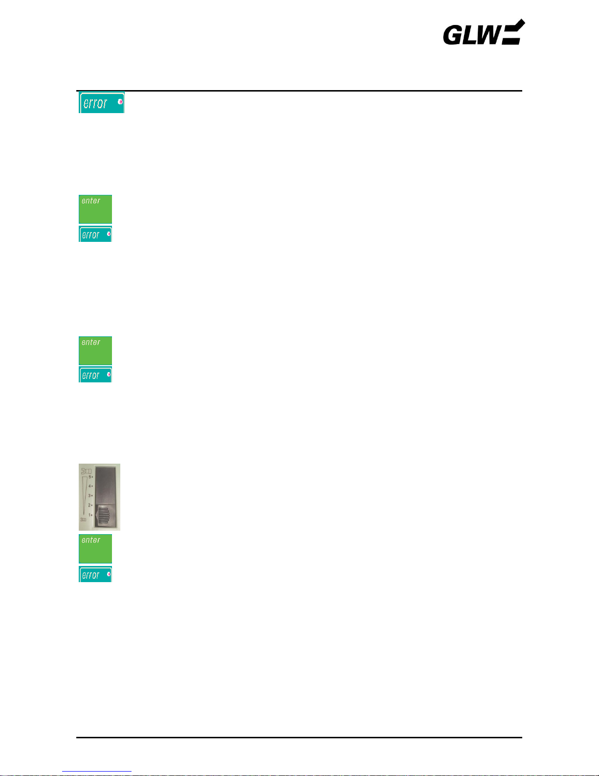
9. Set optimum force range
Push force range adjusting slide to position 1.
Set mode 1.
Perform crimping without crimp contact inserted by pressing the foot switch.
If lights up, check the adjustment of the dies (see steps 6 and 7).
Perform crimping with wire and crimp contact inserted.
!
Pay attention to correct cross section according to the company supplementary
sheet.
If lights up, push up the slide one step and press .
Repeat until no longer lights.
To compensate for any material tolerances, push the setting slide up another step.
Figure 9 Getting the device ready

START-UP EC 65
12/09 13
10. Set the optimum opening distance
Press the top button until all 4 LEDs light up. The maximum opening distance is set.
Perform crimping.
!
Changes in the setting only become effective after the next crimping process.
If the opening distance is too large press the bottom button (3 LEDs light up) and perform a new
crimping.
Repeat the process until the optimum opening distance is set.

OPERATION EC 65
12/09 14
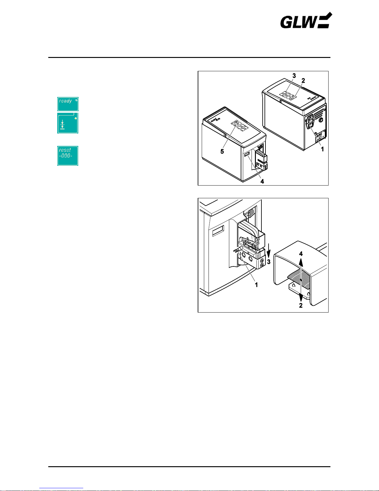
One-step crimping
1. Set mode 1
Switch on the EC 65 at the power switch (1)
(press I).
lights up (2).
Set mode 1 (3).
Read counter (4) if necessary and
reset to 0 with (5).
2. Crimp crimp contact
Centre the crimp contact (1) on the bottom die.
Insert wire (2) in the crimp contact.
!
Pay attention to correct cross section
according to the company
supplementary sheet.
Press the foot switch (3) until the crimp die is fully
closed (4).
The crimp die (5) opens automatically, the foot
switch (6) can be released.
Remove the crimp contact with crimped wire (7).
!
lights up in the case of
defective crimping. Consult the
FAULTS chapter.
3. Taking out of operation
Read counter (1) if necessary.
Switch off the EC 65 at the power switch (2)
(press 0).
Figure 10 Set mode 1
Figure 11 Crimp crimp contact
Figure 12 Taking out of operation

OPERATION EC 65
12/09 15
Two-step crimping
1. Set mode 2
Switch on the EC 65 at the power switch (1)
(press I).
lights up (2).
Set mode 2 (3).
Read counter (4) if necessary and
reset to 0 with (5).
2. Clamp crimp contact
Centre the crimp contact (1) on the bottom die.
!
Pay attention to correct cross section
according to the company
supplementary sheet.
Press the foot switch (2) until the crimp contact is
clamped (3).
Release the foot switch (4).
Figure 13 Set mode 2
Figure 14 Clamp crimp contact

OPERATION EC 65
12/09 16
3. Crimp crimp contact
Insert wire (1) in the crimp contact.
Press the foot switch (2) until the crimp die is fully
closed (3).
The crimp die (4) opens automatically, the foot
switch (5) can be released.
Remove the crimp contact with crimped wire (6).
!
lights up in the case of
defective crimping. Consult the
FAULTS chapter.
4. Taking out of operation
Read counter (1) if necessary.
Switch off the EC 65 at the power switch (2)
(press 0).
Figure 15 Crimp crimp contact
Figure 16 Putting out of operation
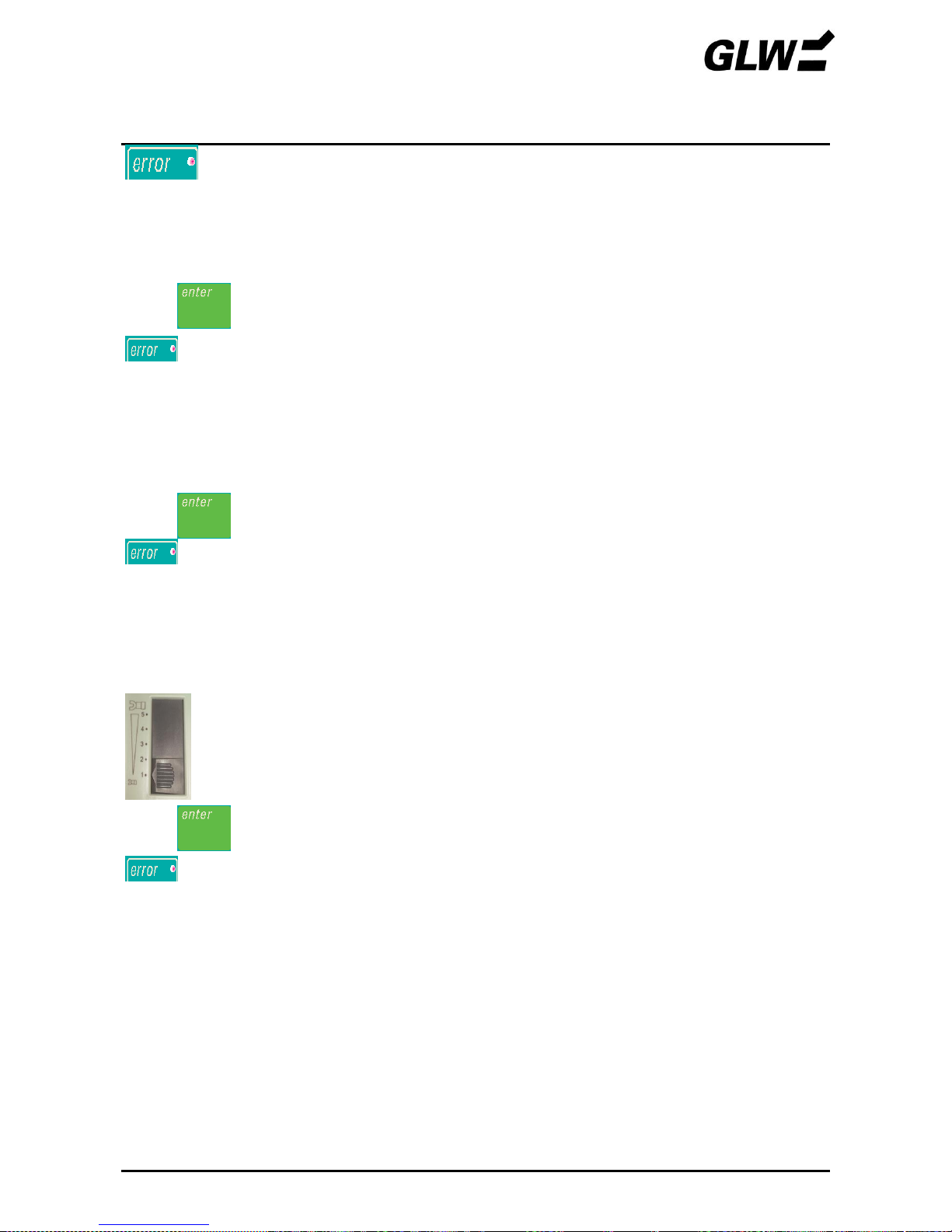
FAULTS EC 65
08/16 17
lights
This fault may be caused by:
1. Foot switch released too early
The crimp die opens immediately to the initial position when the foot switch is released too early.
Press .
goes out.
Repeat crimping.
2. Wrong cross section chosen.
When inserting a too large crimp contact or other unsuitable objects the crimping process is
aborted due to overloading and the crimp die opens immediately to the initial position.
Press .
goes out.
Repeat crimping with the right cross section according to the company supplementary sheet.
3. Incorrectly set force range
If the resistance reached in the crimping process exceeds the range set on the force range
adjusting slide, the crimp die opens immediately to the initial position.
Push the force range adjusting slide up one step.
Press .
goes out.
Repeat the crimping process until the optimum force range is set.
FAULTS EC 65
08/16 18
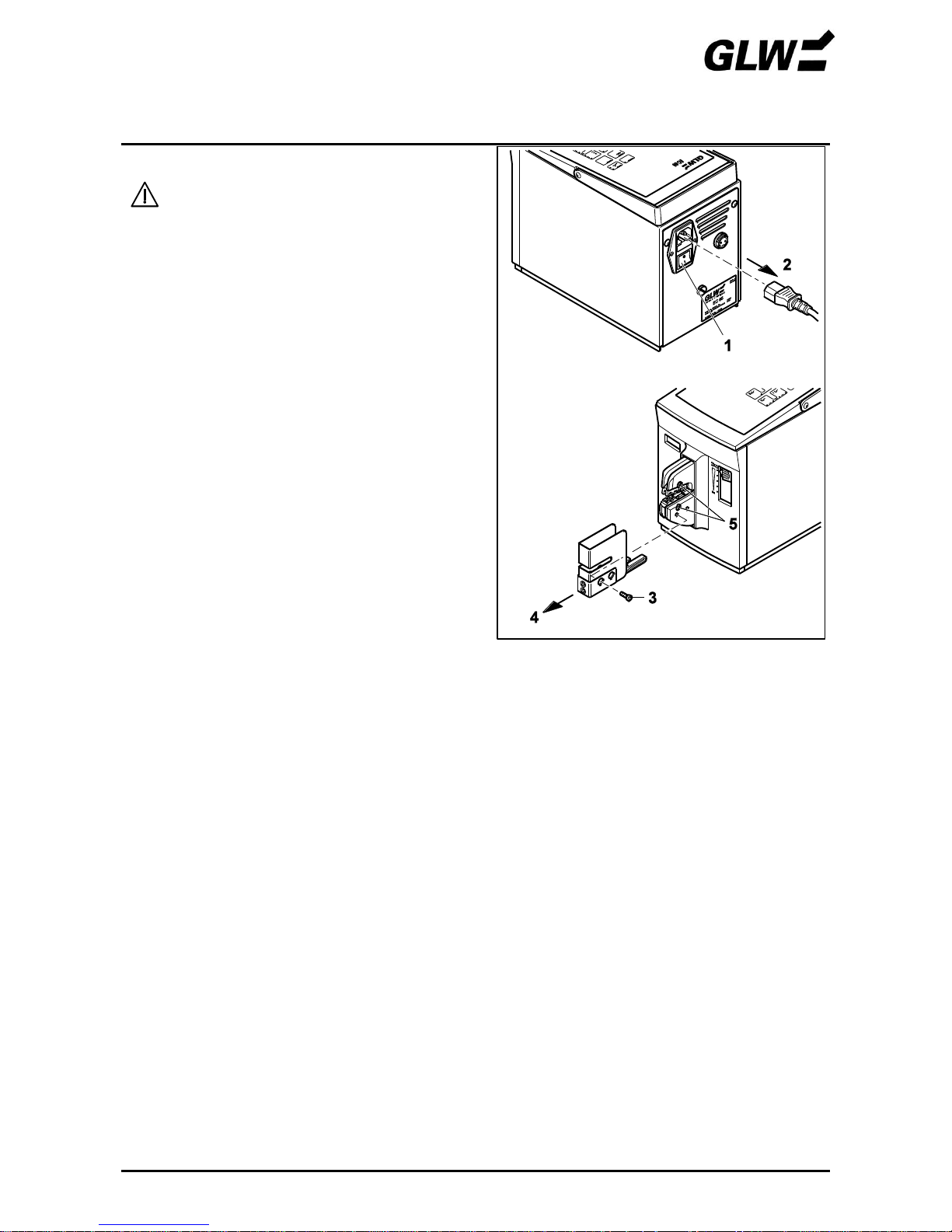
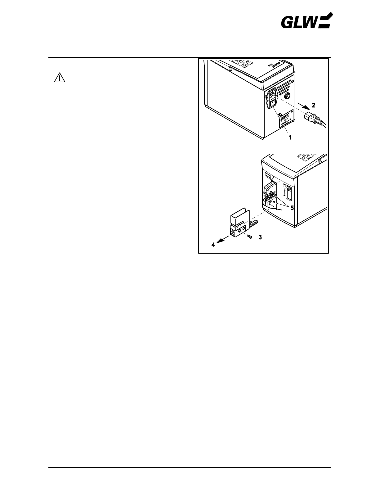
4. Dies not adjusted correctly
The protective cover must be pulled
off, pull out the mains plug!
• Switch off the EC 65 at the power switch (1)
(press 0).
• Pull out the mains plug (2).
Unscrew the screw (3).
Pull off the protective cover (4).
Loosen the screws (5).
Perform steps 4 to 10 of the START-UP.
Figure 17 Loosen dies

FAULTS EC 65
08/16 19
does not light or EC 65 cannot be switched on
This fault may be caused by:
1. No mains connection
Check whether the mains plug at the mains connection of the EC 65 and the shock-proof plug are
connected to the mains socket.
Make sure that the power supply at the mains socket is okay.
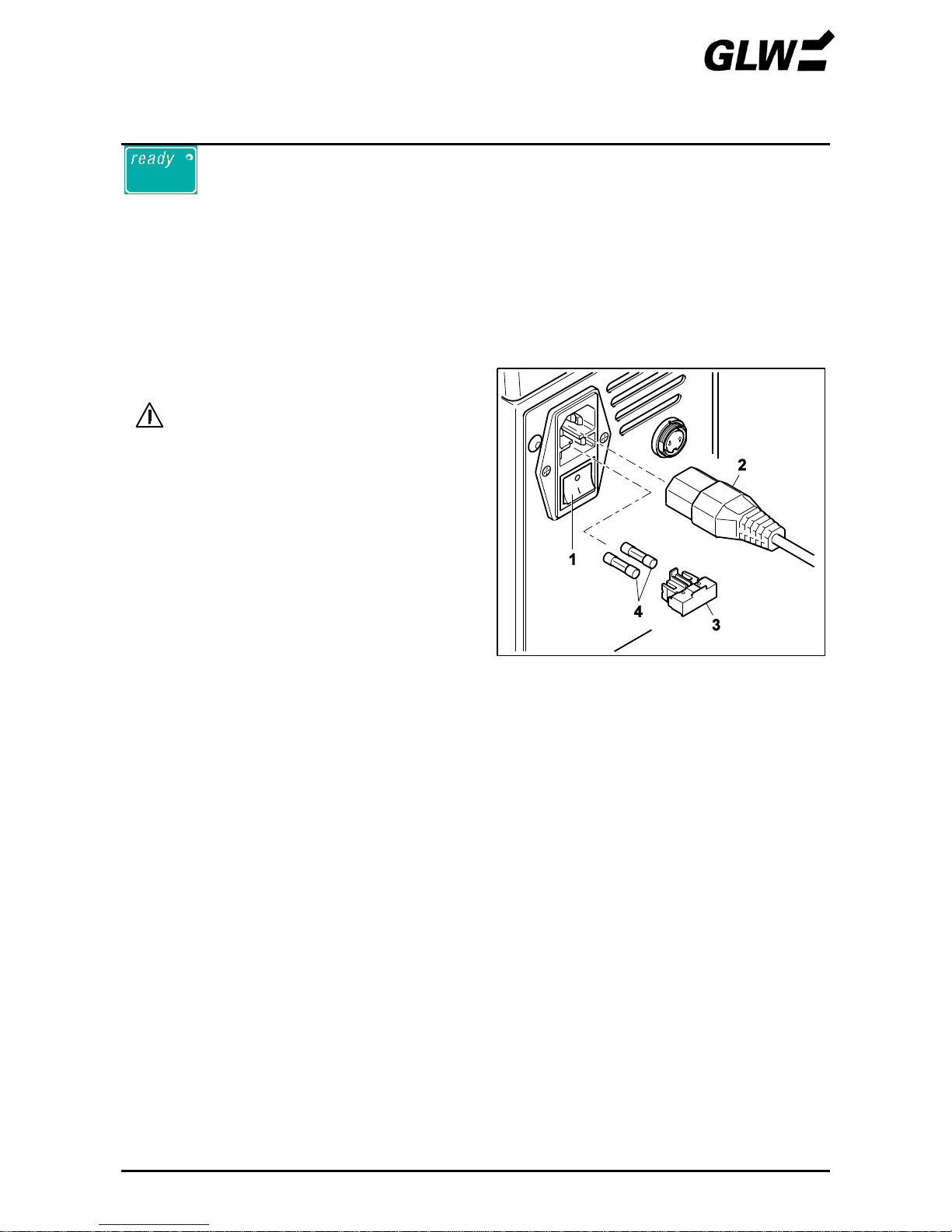
2. Mains fuse defective
The mains connection must be
opened, pull out the mains plug!
Switch off the EC 65 at the power switch (1) (press
0).
Pull out the main plug (2).
Pull out the fuse holder (3).
Check the main fuses (4).
Replace the mains fuse (see SPARES chapter for
part numbers).
Push in the fuse holder.
!
The fuse holder must snap in.
Figure 18 Check the mains fuse

SPARE PARTS EC 65
08/16 20
The spares listed below can be ordered by specifying the appropriate part numbers.
Part
Part no.
Quantity
Dies
Other crimping - dies see
sheet 23 – 24 and
www.glw.de/Crimping
Protective cover
Other protective covers see
sheet 23 - 24 and
www.glw.de/Crimping
Foot switch
005058
1 pc.
Mains fuse 230V T1.25A
Mains fuse 115V T2.50A
001805
001806
2 pcs.

TECHNICAL DATA EC 65
08/16 21
Mains connection ................................................................................ 230 V / 50 Hz (115 V / 60 Hz)
Power consumption ............................................................................................................... 160 VA
Max. pressing force .................................................................................................................. 10 kN
Pressing time ............................................................................................................................ < 1 s
Counter .......................................................................................................... 6-digit LCD, resettable
Dimensions (W x H x D) .................................................................................... 140 x 222 x 320 mm
Weight of basic device ..............................................................................................................10 kg
Weight of foot switch ................................................................................................................1.2 kg
Acoustic pressure emissions LpA ..................................................................................... < 70 dB (A)
Rating plate
Made in
Serial number
Year
Power consumption
230V/50Hz (115V/60Hz)
Manufacturer
Manufacturer address
Machine type
Main connection
EC Conformity Declaration EC 65
03/16 22
Manufacturer: GLW GmbH
Address: Steinbeisstrasse 2
88353 Kisslegg
Germany
We hereby declare that the machine described below complies with the pertinent basic safety and
health requirements of the EC machine directive in design and construction and version marketed
by us. This declaration will lose its validity in the case of modifications to the machine which are not
approved by us.
Name of the
equipment: Crimping machine for crimp contacts
Machine type: EC 65
EC 65 US (115 V)
Pertinent EG- Machine directive 2006/42/EG
EG-Guidance: EG- Low-voltage directive 2006/95/EG
EG- Directive Electromagnetic Compatibility 2004/108/EG
Applied DIN EN ISO 12100-1 and -2:2004
harmonised DIN EN ISO 13857:2008
standards DIN EN 349:2008
DIN EN 60204-1:2006
DIN EN 50081-1:1993
DIN EN 50082-2:1994
Place, date Kisslegg, 16. March 2016
Legally binding signature:
Information about signatory: Bruno Weiland
Responsible person for Documents: Bruno Weiland

ACCESSORIES
Crimping Dies and Protective Covers EC 65
12/09 23
EC D0140
EC PC06
EC D6099
EC PC 04.1
0,14-1,0 / 1,5 / 2,5 / 4 mm²
6 / 10 mm²
EC E0160
EC PC05
EC E1025
EC PC01
0,08-0,14/ 0,25-0,34/ 0,5-0,75/ 1-1,5/ 2,5 / 4 / 6
mm²
10 / 16 / 25 mm²
EC E3550
EC PC01
EC E4099TW
EC PC07
35 / 50 mm²
2x 4 / 2x 6 / 2x 10 mm² TWIN
EC I0560
EC PC06
EC I0560AS
EC PC06
0,5 – 6 mm²
0,5 – 6 mm² asy.
EC I0115
EC PC06
EC I1525F
EC PC06.1
0,10 – 1,5 mm²
1,5² - 2,5 mm²
Other crimping - dies see www.glw.de/Crimping
ACCESSORIES
Crimping Dies and Protective Covers EC 65
12/09 24
EC R0115
EC PC02
EC R0560
EC PC02
0,1-0,5 / 0,5-1 / 0,5-1,5 mm²
0,5-1,5 / 2,5 / 4-6 mm²
EC R0508A
EC PC02
EC R1025A
EC PC02
0,5 – 0,75 mm²
1,0 – 2,5 mm²
EC T0140
EC PC04
EC T4099N
EC T4099E
øa/i 5/3 - 6,5/4,5 - 7/4,5
EC PC03
øa/i 5/3 - 6/4 - 8/5
0,34-0,75 /1-1,5 / 2,5 mm²
4 / 6 / 10 mm²
EC T4099P
EC T4099F
(NFC 20-130)
øa/i 5/3 - 5,5/3,8 - 8/5
EC PC03
EC T0599Q
EC PC03
øa/i 5/2,7- 5,5/3,3-
6,8/4,2
4 / 6 / 10 mm²
0,5 -1,5 / 1,5 - 2,5 / 4 - 6 / 10 mm²
EC T160Q
EC PC04.1
EC I1425UF
EC PC04.1
16 mm²
0,14-0,5 / 0,5-1,5 / 1,5-2,5 mm²
Other crimping - dies see www.glw.de/Crimping
ACCESSORIES
Locator for Flat Tab Terminals (Open Barrel) EC 65
12/09 25
Locator
Item No. EC LOC01 suitable for:
> Female Terminals 6,3 DIN 46247
> Die EC R0560
> Protective Cover EC PC02
Spare part: Locator plate Item No. EC 0001
Item No. EC LOC02 suitable for:
> Female Terminals 4,8 DIN 46247
> Dies EC R0115; EC R0560
> Protective Cover EC PC02
Spare part: Locator plate Item No. EC 0002
Item No. EC LOC03 suitable for:
> Female Terminals 2,8x5 DIN 4624
> Dies EC R0115;
> Protective Cover EC PC02
Spare part: Locator plate Item No. EC 0003
Item No. EC LOC04 suitable for:
> Female Terminals 2,8x6 DIN 46247
> Dies EC R0115;
> Protective Cover EC PC02
Spare part: Locator plate Item No. EC 0004
Item No. EC LOC05 suitable for:
> Male Terminals 6,3 DIN 46247
> Dies EC R0560
> Protective Cover EC PC02
Spare part: Locator plate Item No. EC 0005
Item No. EC LOC06 suitable for:
> Male Terminals 6,3 Typ HN DIN 46247
> Dies EC R0560
> Protective Cover EC PC02
Spare part: Locator plate Item No. EC 0006
Other versions see www.glw.de/Crimping

EC 65
GLW GmbH
Steinbeisstraße 2
88353 Kisslegg
Germany
Phone +49 7563 9123-0
Fax +49 7563 9123-99
All rights to this operating manual reserved by
GLW.
Reprinting, reproduction or translation, even in
part, are prohibited without express permission.
2016 GLW GmbH
EC 65
Mode d'emploi
Sertisseuse électrique EC 65
Edition : 08/2016
A conserver !


SOMMAIRE EC 65
04/2012
Sécurité
1 – 3
Consignes fondamentales
1
Symboles
1
Dangers de la machine
1
Application conforme à la destination
2
Sources de risques
2
Postes de travail
2
Dispositifs de protection
2
Opérateurs autorisés
3
Garantie
3
Description
4 – 7
Fourniture
4
Utilisation
4
Matrices
4
Eléments de commande – vue d'ensemble
5
Eléments de commande – fonction
6
Mise en service
8 - 13
Utilisation
14 – 16
Sertir en une étape
14
Sertir en deux étapes
15
Anomalies
17 – 19
allumé
17
non allumé ou EC 65 ne peut être mis sous tension
19
Pièces de rechange
20
Caractéristiques techniques
21
Plaquette signalétique
21
Déclaration de conformité CE
22
Accessoires
23 - 25


SECURITE EC 65
04/2012 1
Consignes fondamentales
La connaissance et le respect des consignes de sécurité sont la condition de base pour une
utilisation sûre et un fonctionnement sans problèmes de l'EC 65.
Il en va de votre sécurité !
Les consignes de sécurité doivent être respectées par toutes les personnes travaillant avec
l'EC 65.
En plus de cela doivent être observées toutes les règles et dispositions, en particulier celles ayant
trait à la prévention des accidents, applicables à l'emplacement.
Symboles
Ce mode d'emploi utilise les symboles suivants :
signale un risque d'accident et de blessure ou un endommagement possible de l'EC 65.
!
désigne des instructions d'application.
Dangers de la machine
L'EC 65 présente une conception conforme aux règles de sécurité et a été soumis à un contrôle et
une réception de sécurité.
Cet appareil est équipé de dispositifs de protection.
En dépit de ces précautions, une manipulation incorrecte ou un emploi abusif font courir des
dangers relatifs
à l'intégrité physique de l'opérateur
à la machine.
L'EC 65 doit seulement s'utiliser
en conformité avec le domaine d'application prévu
dans un bon état de sécurité.
Toutes les personnes chargées de la mise en service, de l'utilisation et de la remise en état de
l'EC 65 doivent
présenter les qualifications appropriées et
scrupuleusement observer les indications de ce mode d'emploi.

SECURITE EC 65
04/2012 2
Application conforme à la destination
L'EC 65 se destine exclusivement au sertissage.
Il est seulement permis d'utiliser à cet égard des matrices à sections adéquates en conformité
avec la fiche d'accompagnement.
Il ne faut en aucun cas introduire des pièces métalliques massives ou objets de même type. Ils
endommageraient la matrice.
Les transformations découlant de propres initiatives et dépassant le changement d'équipement de
l'EC 65 sont interdites par mesure de sécurité !
!
Le respect de toutes les consignes et des conditions d'utilisation prescrites fait partie
de l'application conforme à la destination.
Sources de risques
L'EC 65 a seulement le droit d'être mise en service avec le capot.
Il est nécessaire de débrancher la fiche avant tous travaux exigeant la dépose du capot (par ex.
ajustage de matrices) et de mettre l'interrupteur marche/arrêt hors tension en cas de pauses ou de
non-utilisation.
Postes de travail
Doivent être évités comme lieux de fonctionnement et de stockage :
Lieux humides ou poussiéreux
Lieux exposés à une grande chaleur, à un rayonnement solaire direct ou à de basses
températures (plage de service : 10 °C à 40 °C).
Ne pas verser de liquides sur l'EC 65.
Ne pas faire subir des secousses et chocs importants à l'EC 65.
Dispositifs de protection
L'EC 65 se met hors tension par
l'interrupteur marche/arrêt (0 enfoncé, LED sombre)
débranchement de la fiche secteur
extraction du capot
Le capot a pour but d'assurer la sécurité de l'opérateur. Il n'a pas le droit d'être modifié, retiré ou
désactivé par des transformations.
Une étiquette appliquée sur le fond de l'appareil signale les risques.

SECURITE EC 65
04/2012 3
Opérateurs autorisés
Seuls des opérateurs autorisés et instruits ont le droit d'utiliser l'EC 65.
L'opérateur est responsable vis-à-vis de tiers dans la zone de travail.
L'exploitant doit
rendre le mode d'emploi accessible à l'opérateur
s'assurer que l'opérateur l'a lu et compris.
Garantie
Nos "Conditions générales de vente et de livraison" s'appliquent. Celles-ci sont à la disposition de
l'exploitant au plus tard à la conclusion du contrat.
Les recours en garantie et engagements de responsabilité en matière de dommages corporels et
matériels sont exclus dans les cas suivants :
Utilisation de l'EC 65 non-conforme à la destination.
Postes de travail non conformes.
Application non conforme et application dépassant le cadre défini par le mode d'emploi.
Transformations de construction de l'EC 65 relevant d'une propre initiative.
Exploitation poursuivie de l'EC 65 en cas d'anomalies constatées.
Fonctionnement de l'EC 65 au-delà de 500000 opérations de sertissage. Après 500000
opérations de sertissage, une maintenance doit être effectuée par le fabricant. La maintenance
prévue est signalée par la LED sur le tableau de commande.
Montage de matrices / réparations non conformes.
!
Utiliser seulement des matrices d'origine et pièces de rechange d'origine.

DESCRIPTION EC 65
04/2012 4
Fourniture
Figure 1 Fourniture
1
Appareil EC 65
4 Pédale
2
Capot
5
Mode d'emploi
3
Câble d'alimentation
Utilisation
La sertisseuse électrique EC 65 sert à presser des contacts à sertir.
L'utilisation de diverses matrices permet de réaliser des types de contacts très variés dans une
grande plage de sections. En raison de ce grand domaine et des cycles courts (< 1 s), l'EC 65
convient aussi bien à des ateliers qu'à des systèmes de confection de câbles complexes.
Matrices
Les matrices disponibles sont répertoriées dans les fiches d'accompagnement. A chaque matrice
est affecté un capot avec une fente ajustée.

DESCRIPTION EC 65
04/2012 5
Eléments de commande – vue d'ensemble
Figure 2 Eléments de commande
1
Panneau de commande
7
Prise pédale
2
Compteur de pièces
8
Prise secteur
3
Curseur de réglage de plage de force
9
Fusibles secteur
4
Matrice
10
Interrupteur marche/arrêt
5
Capot
11
Pédale
6
Poignée

DESCRIPTION EC 65
04/2012 6
Eléments de commande - fonction
1
Panneau de
commande
Sert à la sélection de fonctions et à l'affichage d'états
d'appareil.
LED-ready
Signale que l'appareil est prêt.
LED-error
Indique un sertissage précédent incorrect ou une
anomalie (un nouveau sertissage est impossible tant
que la LED est allumée).
LED-service
Montre une maintenance prévue de l'EC 65 (pour
garantir une qualité de travail constante, il faut faire
effectuer une maintenance par le fabricant après
500000 sertissages).
Touche-reset
Quand l'EC 65 est sous tension, remet le compteur de
pièces à zéro.
Touche-enter
Effacer la LED . L'EC 65 est opérationnelle.
Touche-état de
fonctionnement 1
Commute l'EC 65 en mode 1 (LED allumée). En mode
1, le sertissage s'effectue en une seule étape. Une
pression de la pédale referme la matrice entièrement
puis la rouvre.
Touche-état de
fonctionnement 2
Commute l'EC 65 en mode 2 (LED allumée). En mode
2, le sertissage s'effectue en deux étapes. Après une
pression de la pédale, le contact sera bloqué dans la
matrice sans être serti à ce stade. Maintenant on peut
introduire le conducteur dans le contact. Une nouvelle
pression de la pédale fermera la matrice complètement
puis la rouvrira.
Touches-limitation de
l'ouverture
Une pression de la touche supérieure (ouvrir) ou
inférieure (fermer) modifie l'ouverture de la matrice. Les
LED indiquent l'ouverture :
4 LED allumées : ouverture max.
Pas de LED allumée : ouverture min.
Un nouveau réglage ne devient actif qu'après
l'exécution du prochain sertissage.
2
Compteur de pièces
Le compteur saisit chaque sertissage accompli. Les
sertissages interrompus par une erreur ne sont pas
relevés. Le contenu du compteur reste enregistré
pendant env. 1 semaine, aussi quand l'appareil est
éteint.
999999
DESCRIPTION EC 65
04/2012 7
3
Curseur de réglage de
la plage de force
Ce curseur permet de régler la plage dans laquelle la
matrice est comprimée avec la force maximale. Si la
matrice rencontre un obstacle en dehors de cette plage,
la pince à sertir s'ouvre immédiatement afin d'éviter un
endommagement de la matrice ou de la pièce mal
insérée.
Position 1 : plage min.
Position 5 : plage max.
4
Matrice
Positionne le contact et le presse avec le conducteur.
Est constituée des parties supérieure et inférieure.
Celles-ci peuvent être remplacées en fonction de
l'application.
5
Capot
Empêche des blessures aux doigts et aux mains dans la
zone à risques de la matrice.
L'EC 65 travaille seulement quand le capot est
entièrement raccordé.
6
Poignée
Sert à transporter l'EC 65.
7
Prise pédale
Prise de pédale sur l'appareil.
8
Prise secteur
Prise de câble d'alimentation sur l'appareil.
9
Fusibles secteur
Fusibles intégrés dans la prise secteur, fusibles fins
(2x).
10
Interrupteur
d'alimentation
Enclenche (I enfoncé) ou coupe l'alimentation
(0 enfoncé). Après la mise sous tension, la LED
s'allume sur le panneau de commande.
11
Pédale
Une pression de la pédale déclenche le sertissage.
La pédale doit rester enfoncée jusqu'à ce que la matrice
soit entièrement fermée (mode 1) ou que le contact soit
bloqué (mode 2).
Si la LED est allumée sur le panneau de
commande, le sertissage ne peut être opéré.
MISE EN SERVICE EC 65
04/2012 8
1. Choix de l'emplacement
L'emplacement doit être plan et horizontal.
!
Les conditions du chapitre SECURITE, section Postes de travail, doivent être
respectées.
2. Dépose du capot
Dévisser la vis (1).
Retirer le capot (2).
3. Monter la matrice
!
Tenir compte de la position de
montage :
Petite section à l'avant.
Grande section à l'arrière.
Introduire la matrice inférieure (1).
Serrer légèrement (2) la vis.
Insérer la matrice supérieure (3).
Serrer légèrement (4) la vis.
Figure 3 Retirer le capot
Figure 4 Monter la matrice
MISE EN SERVICE EC 65
04/2012 9
4. Monter le capot
• Insérer la broche de sécurité (1) dans la
matrice inférieure et insérer le capot (2) jusqu'à ce
que celui-ci s'enclenche de façon perceptible.
! Un capot non / mal monté coupe
l'alimentation de l'EC 65.
5. Raccorder / allumer l'EC 65
Raccorder la pédale (1) à la prise
correspondante.
Raccorder la fiche secteur (2) à la prise secteur
de l'appareil et la fiche de sécurité (3) à la prise
de courant.
Allumer l'EC 65 en réglant l'interrupteur
d'alimentation (4) sur I.
s'allume (5).
Figure 5 Monter le capot
Figure 6 Raccorder / allumer l'EC 65

MISE EN SERVICE EC 65
04/2012 10
6. Centrer les matrices
!
Comme les alésages ont du jeu par
rapport aux vis de fixation, les deux
matrices peuvent être décalées entre
elles.
Le mode d'ajustage suivant (étapes 6
et 7) permet un centrage / ajustage des
matrices.
Appuyer sur + en même
temps (1).
+ clignotent (2).
Déplacer le curseur de réglage de la plage de
force (3) en position 1.
Presser la pédale (4) et la maintenir enfoncée.
La matrice (5) se ferme lentement jusqu'à ce
qu'elle rencontre une résistance et se centre.
Relâcher la pédale (6).
!
Si l'on relâche la pédale avant la
fermeture de la matrice, celle-ci
s'ouvre toute seule, le mode d'ajustage
sera quitté et s'allumera.
Figure 7 Centre les matrices
MISE EN SERVICE EC 65
04/2012 11
7. Ajustage des matrices
Déconnecter le capot. Débrancher la
fiche secteur !
Eteindre l'EC 65 en réglant l'interrupteur
d'alimentation (1) sur 0.
Débrancher la fiche (2).
Retirer le capot (3).
Contrôler le centrage des matrices. Les réajuster
si nécessaire (4).
Serrer les vis (5).
Monter le capot (6) et serrer la vis (7).
Figure 8 Ajuster les matrices
MISE EN SERVICE EC 65
04/2012 12
8. Rendre l'appareil prêt
Brancher la fiche (1).
Régler l'interrupteur d'alimentation (2) sur I.
s'allume (3).
Presser la pédale (4).
La matrice (5) s'ouvre automatiquement. La
pédale (6) peut être relâchée.
s'allume (7).
Presser (8).
L'appareil est prêt.
!
Le mode 2 est réglé.
Contrôler le mode avant chaque
utilisation.
9. Régler la plage de force optimale
Pousser le curseur de réglage de la plage de force en position 1.
Régler le mode 1.
Effectuer un sertissage sans contact introduit par pression de la pédale.
Au cas où s'allume pendant cette opération, contrôler l'ajustage des matrices (voir
étapes 6 et 7).
Effectuer le sertissage avec le conducteur et le contact insérés.
!
Veiller à la bonne section conformément à la fiche d'accompagnement.
Si est allumé, lever le curseur d'un cran et presser .
Répéter l'opération jusqu'à ce que ne soit plus allumé.
Pour compenser des tolérances de matériel, pousser le curseur d'un cran vers le haut.
Figure 9 Rendre l'appareil prêt

MISE EN SERVICE EC 65
04/2012 13
10. Régler la course d'ouverture optimale
Presser la touche supérieure jusqu'à ce que les 4 LED soient allumées. La course
d'ouverture maximale est réglée.
Effectuer un sertissage.
!
Les changements de réglage n'agissent qu'après l'exécution du prochain sertissage.
Si l'ouverture est trop grande, presser la touche inférieure (3 LED allumées) et effectuer le
nouveau sertissage.
Répéter l'opération jusqu'à ce que la course d'ouverture optimale soit réglée.

UTILISATION EC 65
04/2012 14
Sertir en une étape
1. Régler le mode 1
Allumer l'EC 65 en réglant l'interrupteur (1)
sur I.
s'allume (2).
Régler le mode 1 (3).
Relever au besoin le compteur (4) et le remettre
à zéro avec (5).
2. Sertir le contact
Centrer le contact (1) sur la matrice inférieure.
Introduire le conducteur (2) dans le contact.
!
Veiller à la bonne section
conformément à la fiche
d'accompagnement.
Presser la pédale (3) jusqu'à ce que la matrice soit
complètement fermée (4).
La matrice (5) s'ouvre automatiquement. La
pédale (6) peut être relâchée.
Retirer le contact avec le conducteur serti (7).
!
En cas de sertissage incorrect,
s'allume. Consulter le chapitre
ANOMALIES pour plus de détails.
3. Mettre hors tension
Relever si nécessaire le compteur (1).
Eteindre l'EC 65 en réglant l'interrupteur (2) sur 0.
Figure 10 Régler le mode 1
Figure 11 Sertir le contact
Figure 12 Mettre hors tension

UTILISATION EC 65
04/2012 15
Sertir en deux étapes
1. Régler le mode 2
Mettre l'EC 65 sous tension en réglant
l'interrupteur (1) sur I.
s'allume (2).
Régler le mode 2 (3).
Relever au besoin le compteur (4) et le remettre
à zéro avec (5).
2. Bloquer le contact
Centrer le contact (1) sur la matrice inférieure.
!
Veiller à la bonne section
conformément à la fiche
d'accompagnement.
Presser la pédale (2) jusqu'à ce que le contact soit
bloqué (3).
Relâcher la pédale (4).
Figure 13 Régler le mode 2
Figure 14 Bloquer le contact

UTILISATION EC 65
04/2012 16
3. Sertir le contact
Introduire le conducteur (1) dans le contact.
Presser la pédale (2) jusqu'à la fermeture
complète de la matrice (3).
La matrice (4) s'ouvre automatiquement. La
pédale (5) peut être relâchée.
Enlever le contact avec le conducteur serti (6).
!
En cas de sertissage incorrect,
s'allume. Consulter le chapitre
ANOMALIES pour plus de détails.
4. Mettre hors tension
Relever au besoin le compteur (1).
Mettre l'EC 65 hors tension en réglant
l'interrupteur (2) sur 0.
Figure 15 Sertir le contact
Figure 16 Mettre hors tension

ANOMALIES EC 65
04/2012 17
allumé
Cette anomalie peut être due aux opérations suivantes :
1. Pédale relâchée trop tôt
En cas de relâchement prématuré de la pédale, la matrice s'ouvre immédiatement jusqu'à la
position initiale.
Presser .
s'éteint.
Répéter le sertissage.
2. Section mal sélectionnée
En cas d'insertion d'un trop gros contact ou d'autres objets inappropriés, le sertissage est
interrompu par surcharge et la matrice s'ouvre jusqu'à la position initiale.
Presser .
s'éteint.
Répéter le sertissage avec la bonne section, conformément à la fiche d'accompagnement.
3. Plage de force mal réglée
Si la résistance atteinte lors du sertissage dépasse la plage réglée sur le curseur, la matrice
s'ouvre immédiatement jusqu'à la position initiale.
Pousser le curseur de réglage de la force d'un cran vers le haut.
Presser .
s'éteint.
Répéter le sertissage jusqu'à ce que la plage de force soit réglée de façon optimale.

ANOMALIES EC 65
04/2012 18
4. Matrices mal ajustées
Retirer le capot. Débrancher la fiche !
•Eteindre l'EC 65 en réglant l'interrupteur (1) sur 0.
•Débrancher la fiche (2).
Dévisser la vis (3).
Retirer le capot (4).
Dévisser les vis (5).
Effectuer les étapes 4 à 10 de la MISE EN
SERVICE.
Figure 17 Desserrer les matrices

ANOMALIES EC 65
04/2012 19
non allumé ou EC 65 ne peut être mise sous tension
Cette anomalie peut être due aux faits suivants :
1. Pas de branchement secteur
Vérifier si la fiche secteur est raccordée à la prise secteur de l'EC 65 et si la fiche de sécurité est
raccordée à la prise de courant.
S'assurer que l'alimentation électrique est correcte sur la prise secteur.
2. Fusible secteur défectueux
Ouvrir la prise secteur. Débrancher la
fiche !
Eteindre l'EC 65 en réglant l'interrupteur (1) sur 0.
Débrancher la fiche (2).
Retirer le porte-fusibles (3).
Vérifier les fusibles secteur (4).
Remplacer les fusibles secteur défectueux
(références, voir chapitre PIECES DE
RECHANGE).
Insérer le porte-fusibles.
!
Le porte-fusibles doit s'enclencher.
Figure 18 Contrôler le fusible

PIECES DE RECHANGE EC 65
04/2012 20
Les pièces de rechange mentionnées ci-après peuvent être commandées avec la référence
correspondante.
Pièce
Référence
Quantité
Matrices
voir fiche d'accompagnement et
www.glw.de/Crimping
Capot
voir fiche d'accompagnement et
www.glw.de/Crimping
Pédale
005058
1
Fusible secteur T1,25 A
001805
2

CARACTERISTIQUES TECHNIQUES EC 65
08/16 21
Alimentation secteur .................................................................................................... 230 V / 50 Hz
Puissance absorbée .............................................................................................................. 160 VA
Force de pression max............................................................................................................. 10 kN
Durée de pression ..................................................................................................................... < 1 s
Compteur de pièces ................................ ............................................ 6 chiffres, LCD, réinitialisable
Dimensions (L x H x P) ..................................................................................... 140 x 222 x 320 mm
Poids appareil ...........................................................................................................................10 kg
Poids pédale ............................................................................................................................1,2 kg
Émissions de pression acoustique LpA ............................................................................ < 70 dB (A)
Plaquette signalétique
Pays de fabrication
Numéro de série
Année
Puissance absorbée
Fabricant
Adresse du fabricant
Type de machine
Branchement

Déclaration de conformité CE EC 65
03/16 22
Fabricant : GLW GmbH
Adresse : Steinbeisstraße 2
D-88353 Kisslegg
Germany
Nous déclarons par la présente que la machine dénommée ci-après répond de par sa conception,
sa construction et l'équipement tel que mis en circulation par nous aux dispositions de sécurité et
de santé fondamentales de la directive européenne Machine. Cette déclaration devient nulle dès
lors que la machine fait l'objet de modifications non effectuées en concertation avec nos services.
Désignation du
matériel d'exploitation : Sertisseuse automatique pour contacts
Type : EC 65
Directives CE Directive européenne Machine 2006/42/EG
concernées: Directive européenne Basse Tension 2006/95/EG
Directive européenne Compatibilité Electromagnétique 2004/108/EG
Normes DIN EN ISO 12100-1 et -2:2004
harmonisées DIN EN ISO 13857:2008
appliquées DIN EN 349:2008
DIN EN 60204-1:2006
DIN EN 50081-1:1993
DIN EN 50082-2:1994
Lieu, date Kisslegg, 16. Mars 2016
Signature contractuelle :
Données sur le signataire : Bruno Weiland
Responsable de document: Bruno Weiland

ACCESSORIES
Matrices et capots EC 65
08/16 23
EC D0140
EC PC06
EC D6099
EC PC 04.1
0,14-1,0 / 1,5 / 2,5 / 4 mm²
6 / 10 mm²
EC E0160
EC PC05
EC E1025
EC PC01
0,08-0,14/ 0,25-0,34/ 0,5-0,75/ 1-1,5/ 2,5 / 4 / 6
mm²
10 / 16 / 25 mm²
EC E3550
EC PC01
EC E4099TW
EC PC07
35 / 50 mm²
2x 4 / 2x 6 / 2x 10 mm² TWIN
EC I0560
EC PC06
EC I0560AS
EC PC06
0,5 – 6 mm²
0,5 – 6 mm² asy.
EC I0115
EC PC06
EC I1525F
EC PC06.1
0,10 – 1,5 mm²
1,5² - 2,5 mm²
plus d’information concernant les matrices voyez www.glw.de/Crimping
ACCESSORIES
Matrices et capots EC 65
08/16 24
EC R0115
EC PC02
EC R0560
EC PC02
0,1-0,5 / 0,5-1 / 0,5-1,5 mm²
0,5-1,5 / 2,5 / 4-6 mm²
EC R0508A
EC PC02
EC R1025A
EC PC02
0,5 – 0,75 mm²
1,0 – 2,5 mm²
EC T0140
EC PC04
EC T4099N
EC T4099E
øa/i 5/3 - 6,5/4,5 - 7/4,5
EC PC03
øa/i 5/3 - 6/4 - 8/5
0,34-0,75 /1-1,5 / 2,5 mm²
4 / 6 / 10 mm²
EC T4099P
EC T4099F
(NFC 20-130)
øa/i 5/3 - 5,5/3,8 - 8/5
EC PC03
EC T0599Q
EC PC03
øa/i 5/2,7- 5,5/3,3-
6,8/4,2
4 / 6 / 10 mm²
0,5 -1,5 / 1,5 - 2,5 / 4 - 6 / 10 mm²
EC T160Q
EC PC04.1
EC I1425UF
EC PC04.1
16 mm²
0,14-0,5 / 0,5-1,5 / 1,5-2,5 mm²
plus d’information concernant les matrices voyez www.glw.de/Crimping

ACCESSORIES
Locator pour fiches plates femelles à fût ouvert EC 65
08/16 25
Locators
Art.-Nr. EC LOC01 assorti pour:
> fiches plates 6,3 DIN 46247
> Matrice EC R0560
> Capot EC PC02
Pièce de rechange: Art.-No. EC 0001
Art.-Nr. EC LOC02 assorti pour:
> fiches plates 4,8 DIN 46247
> Matrice EC R0115; EC R0560
> Capot EC PC02
Pièce de rechange: Art.-No. EC 0002
Art.-Nr. EC LOC03 assorti pour:
> fiches plates 2,8x5 DIN 4624
> Matrice EC R0115; EC R0560
> Capot EC PC02
Pièce de rechange: Art.-No. EC 0003
Art.-Nr. EC LOC04 assorti pour:
> fiches plates 2,8x6 DIN 46247
> Matrice EC R0115; EC R0560
> Capot EC PC02
Pièce de rechange: Art.-No. EC 0004
Art.-Nr. EC LOC05 assorti pour:
> fiches plates 6,3 DIN 46247
> Matrice EC R0115; EC R0560
> Capot EC PC02
Pièce de rechange: Art.-No. EC 0005
Art.-Nr. EC LOC06 assorti pour:
> fiches plates 6,3 Typ HN DIN 46247
> Matrice EC R0115; EC R0560
> Capot EC PC02
Pièce de rechange: Art.-No. EC 0006
plus d’information concernant les locators voyez www.glw.de/Crimping

GLW GmbH
Steinbeisstraße 2
D-88353 Kisslegg
Tél. (07563) 9123-0
Fax (07563) 9123-99
Les droits d'auteur sur ce mode d'emploi restent
détenus par GLW.
Toute réimpression, reproduction ou traduction,
intégrale ou partielle, est interdite sans accord
préalable.
2016 GLW GmbH
 Loading...