

GLUX VSP-F2L4 User Manual

1
The Manual of VSP-F2L4 Controller
Contents
Chapter 1 Brief Introduction of VSP-F2L4 Controller................................................................... 2
1.1 Parameters of VSP-F2L4 controller..............................................................................................2
1.2 The signal connection way of LED screen...................................................................................3
1.3 Function Introduction for VSP-F2L4 Controller’s Buttons and Interfaces..................................5
1.3.1 Front Side Introduction of the VSP-F2L4 Controller........................................................5
1.3.2 Introduction for Back Side of the VSP-F2L4 Controller.................................................. 6
Chapter2 Key-press operation of VSP-F2L4 controller...................................................................7
2.1. Use the buttons to switch input signal types................................................................................7
2.2 Adjust the Parameters by Key-press............................................................................................. 7
2.2.1 Product............................................................................................................................... 8
2.2.2 Spec (Adjust and set the parameters of LED screen)........................................................8
2.2.3 Address Setting.................................................................................................................. 9
2.2.4 Color Test......................................................................................................................... 10
2.2.5 IP Address.........................................................................................................................11
2.2.6 Language (Language Select)............................................................................................11
2.2.7 Date Save..........................................................................................................................11
Chapter3. Control software of VSP-F2L4 controller.....................................................................12
3.1Installation and Running Environment for Control Software of VSP-F2L4 Controller.............12
3.2 Communication Setting.............................................................................................................. 13
3.2.1 Serial Port (COM Port) Setting through USB Cable.......................................................13
3.2.2 Network Port Setting........................................................................................................14
3.3 Parameters Introduction of Control Software.............................................................................15
3.4 Address Setting........................................................................................................................... 17
3.4.1. Address setting method 1: (Not normally used)............................................................. 17
3.4.2 The Method 2 for Address Setting: Multiple Setting (whole screen setting)...............19
3.4.3 The method 3 for Address setting: Intelligent Settings................................................... 20
3.5 Color temperature adjustment.....................................................................................................22
3.5.1 Single panel (Box) color temperature adjustment...........................................................23
3.5.2 LED board (module) color temperature adjustment........................................................25
3.6 Manufacturer Set.........................................................................................................................26
Appendix 1 Signal output cutting method of VSD-F2L4 controller (Important).........................27
Signal Horizontal Segmentation of VSP-F2L4 controller................................................................27
(Applicable to all products).............................................................................................................. 27
Signal Vertical Segmentation of VSP-F2L4 Controller....................................................................28
Appendix
Ⅱ
Failure Analysis and Troubleshooting....................................................................29
2
Chapter 1 Brief Introduction of VSP-F2L4 Controller
VSP-F2L4 control system is researched and developed by Glux independently, it
is the third generation and suitable for the new generation LED display products of
Glux. It is a set of network transmission, optical fiber transmission, and with image
scaling, image mirror functions, and supported 1080 p resolution.
1.1 Parameters of VSP-F2L4 controller.
System Name VSP-F2L4 Giga control system
Input Resolution Max input resolution: 2048×1152; Support the video source
which frequency is less than 60 Hz
Output Resolution Max output resolution: 1920×1080
Power Input AC 110~220V, 20W
Signal Input CAT6 cable, 1G network bandwidth, optical fiber signal
input, 2.5G optical fiber bandwidth
Transmission Distance CAT6 cable:≤ 120 meters; optical fiber cable: 10 km.
Video Signal Input
Interface
Video Processing Gray
scale
Communications
Control Port
DMX512 DMX512 is supported
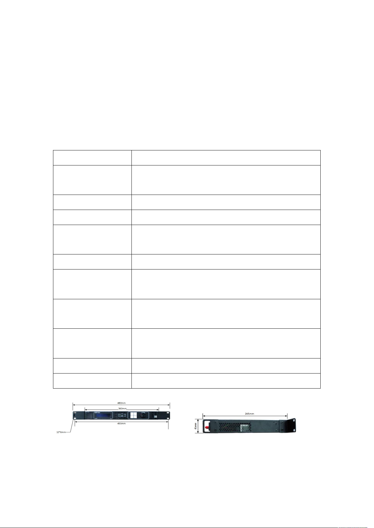
Size 480mm×245mm×45mm
DVI Input, DVI output, HD 3G-SDI input, 3G-SDI output
16-bit gray scale, class 100 adjustable Brightness
USB communications, Network communications and it
support update online.
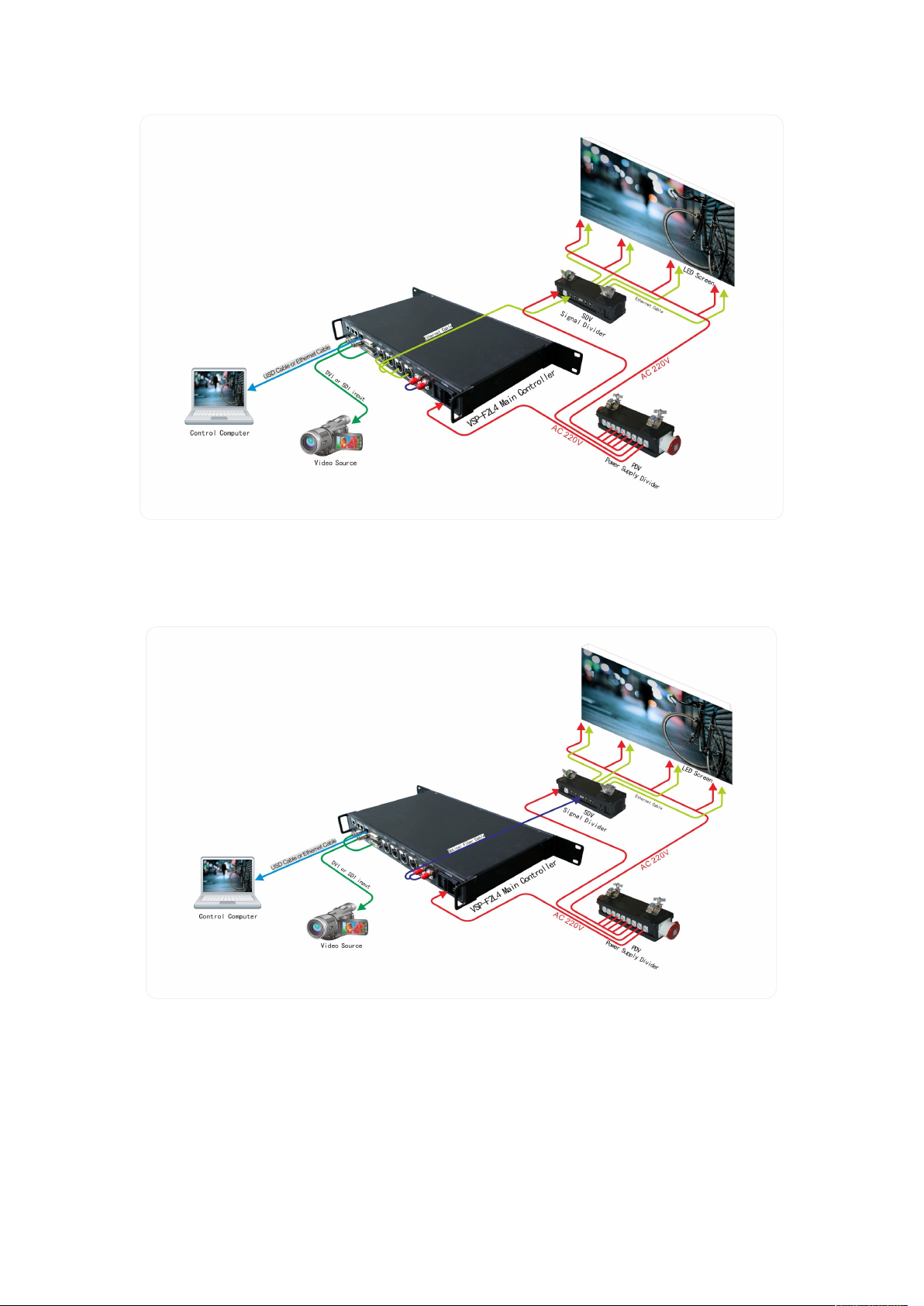
1.2 Signal Connections to the LED screen
There are three connecting methods between VSP-F2L4 controller and LED
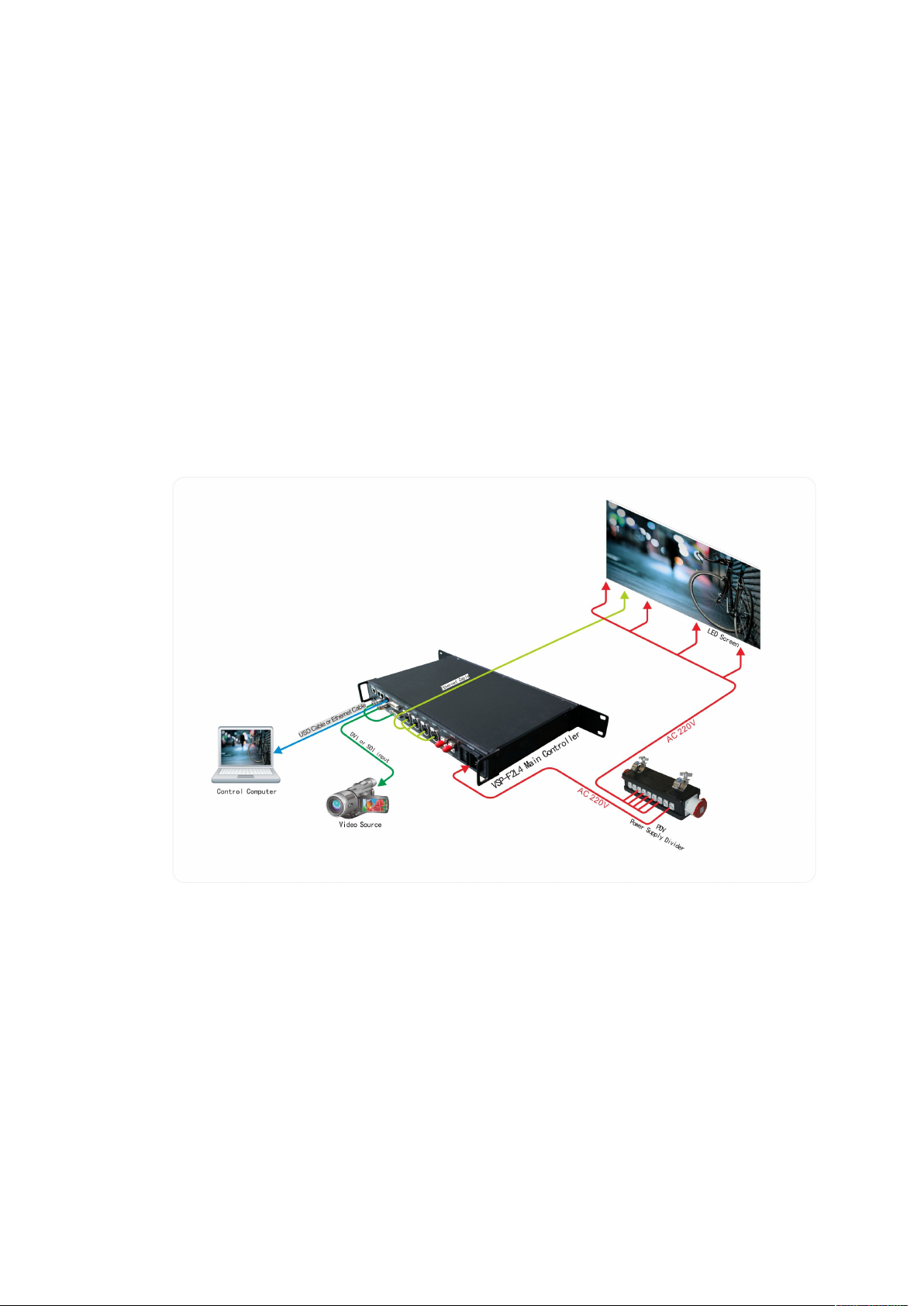
3
screen. Please choose a proper way according to your usage.
Method 1: For use without the Glux signal divider: Link the LED screen with
VSP-F2L4 controller by signal cable. It means that signal is transmitted to the LED
screen directly from the controller’s output port (OUT1~OUT4).
Method 2: With signal divider. Transmit signal from VSP-F2L4 controller’s output
port “OUT1~OUT4”to SDV signal divider’s input port “SIG IN” by CAT6 Ethernet
cable. The signal will be transmitted from SDV signal divider’s interface A1~A4,
B1~B4 to LED screen by signal cable.
Method 3: With signal divider. Transmit signal from VSP-F2L4 controller’s optical
port OUT1~OUT2 to SDV signal divider’s optical input port “ IN” by optical fiber
cable. And then signal will be transmitted from SDV signal divider’s interfaces
A1~A4, B1~B4 to LED screen by signal cable.
Three kinds of connection modes are showed as below:
System signal connection method 1 (Transmission distance≤120m)
Signal be transmitted from controller to LED screen directly
4
System signal connection method 2 (Transmission distance≤150m)
Signal→by CAT6 Ethernet cable→to Signal divider→by signal cable→to screen
System signal connection method 3 (Transmission distance≤10Km)
Signal→by optical fiber cable→to Signal divider→by signal cable→to LED screen
The optical fiber cable type should be single mode.
Which method you choose will depend on the control distance and the size of
LED screen. Method 2 and the method 3 are recommended especially in the case of
larger LED screens or long distance transmission.

5
1.3 Function Introduction for VSP-F2L4 Controller’s Buttons
Input DVI 1920×1080P 60
Output 1024×768P 60
Brightness 70 IC MBI5041
CYSN39 IP 192. 168. 0.6
and Interfaces
1.3.1 Front Side Introduction of the VSP-F2L4 Controller
(1) LCD display interface: Mainly showing the setting and product information,
shown as below.
We can learn the follow information from the interface:
DVI video signal input; Input resolution is 1920×1080P 60Hz;
Output resolution: 1024×768P 60Hz;
The current brightness of the LED panel is class 70 levels; the code of the product is
CYSN39; The IP address of the controller is 192.168.0.6
(2) Working indicating light: When the controller works well it will flash.
A, B, C, D indicates the status of the OUT1 ~ OUT4 four groups’ signal.
(3) Function buttons of VSP-F2l4 controller
The four buttons are SEND/DVI, SEL/SDI1, SETUP/HDMI, and ESC/SDI2.
SEND/DVI button: Click the key to send your setting or select DVI input signal.
SEL/SDI1 button: Click it to enter the next level menu or select SDI1 input signal.
SETUP/HDMI button: Click it to enter setting parameters states or select HDMI
input signal.
ESC/SDI2 button: Press it to return to the previous menu or select SDI2 input signal.
(4) Parameter Control Knob: Turn the knob can browse the submenu items. The
parameter will be higher if the knob is rotating clockwise. If you want to lower the
parameter, please turn the knob counterclockwise.
(5) USB Communication Port: The USB port that is used to communicate with the
control software on computer to set the LED panel parameters.
6
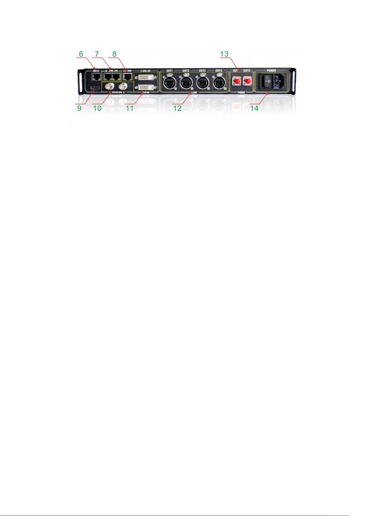
1.3.2 Introduction for Back Side of the VSP-F2L4 Controller
(6) DMX512 signal input port.
(7) Adjust video synchronous In/Out port
(8) Lan-100M is the network communication port that is used to communicate with
the control software on computer to set the LED panel parameters.
(9) HDMI video signal input port.
(10) SDI1 /SDI2 is the SDI video signal input port which is support to the input of
HD SDI signal and 3G SDI signal.
(11) DVI IN is the DVI video signal input port and DVI OUT is the DVI video signal
output port.
(12) OUT1~OUT4 port is four serial network signal output ports of the controller
(13) OUT1~OUT2 port is two serial optical fiber signal output ports of the controller;
(14) Power port is the power input port and the power switch port. AC110~220V
7
Chapter 2 Key-press operation of VSP-F2L4 controller
Input DVI 1920×1080 P 60
Output 1024×768 P
60
Brightness 70 IC MBI5041
CYSN39 IP 192. 168. 0.6
Function
> Product
Spec
Address
Press SETUP/HDMI
enter the parameter
setting mode
2.1. Which buttons to switch input signal types
Please simultaneously press the three keys SEND/DVI, SEL/SDI1, ESC/SDI2 to
enter the mode of switch signal input. Now press the SEND/DVI key for DVI input
signal. Press SEL/SDI1 selects SDI1 input signal, pressing ESC/SDI2 selects SDI2
input signal, pressing the SETUP/HDMI chooses HDMI input signal.
You can also see the input signal types that you choose on the LCD Display
Interface at the same time. Please turn the Parameter Control Knob if you want to exit
the signal-switching mode.
2.2 Adjust the Parameters by Key-press
The LCD Display Interface will show as the below picture after startup, press the
SETUP/HDMI key to enter the parameter setting mode.
Setup Direction:
Symbol description.”>” Means first-level menu, turn the Parameter Control Knob
will scan its sub options. Press the SEL/SDI1 key can entry to second-level menu
(Symbol>>) and press SEL/SDI1 again the symbol “>>”will turn to “#”. In this state,
you can adjust the parameters by turn the Parameter Control Knob.
Please press SEND/DVI to take effect when you finish the adjustment.
Please return to the first-level menu and select “Data Save” option to save the
parameters data when you complete all the parameters setting. Otherwise, the
parameters data will be lost once you reboot the controller.
There are seven sub options of the function option: Product; Spec; Address;
8
Color T; IP Address; Language; Date Save
Input DVI 1920×1080 P 60
Output 1024×768 P60
Brightness 70 IC MBI5041
CYSN39 IP 192. 168. 0.6
Function
Product
> Spec
Address
Function
# Bright 60
X Start 0
Y Start 0
Press SETUP/HDMI to enter the parameter
setting mode, and rotate the control knob to
select the Spec. Option.
Press SEL/SDI1 to enter the parameter and rotate the
control knob to select the Bright, then press the
SEL/SDI1 key to enter, you can see the symbol #.
2.2.1 Product
Please select correct relative parameters of the product under the Product Option
Port: Select a connecting controller port.
Series: Select a style of the product.
Cut Signal: Cut or link the transmission signal of the VSP-F2L4 controller.
Test Mode: Test and check the color of the LED screen.
DMX512 on/off: Please select OFF if there is no DMX512 signal input to the
controller.
Mirror: Set mirror image display effect for LED screen.
Drive IC: Choose correct LED drive IC in your LED panel.
LED PIN1~LED PIN3: Define the pins color of LED lamp to avoid the display color
exchanged.
IN MODE: The mode of display card. Limit range means HDMI 0-235 level gray
mode, Full range means DVI 0-255 gray mode, the default mode is full range.
2.2.2 Spec (Adjust and set the parameters of LED screen)
Bright(Brightness):Adjust the brightness of LED screen, such as the steps of adjust
brightness:
Then rotate the control knob to adjust the brightness level, and click the SEND/DVI to send,
at last save your setting in the save menu.
9
Function
IP Address
Language
> Data save
Function
# Save
Exit
Function
# Save Save Ok
Exit
X start For setting the initial horizontal display position of LED screen. The default
Press SEL/SDI1 to enter the Save menu and
rotate the control knob to select the Save.
Then Select it, you will see the symbol #.
Rotate the control knob to Save. Then Press
SEND/DVI to send, and Press ESC/SDI2 to
exit
value is 0.
Y start: For setting the initial vertical display position of LED screen. The default
value is 0.
X Width: The pixel width per controller port.
Y Height: The pixel height per controller port.
ZOOM H(Horizontal zoom):The actual output pixel width of horizontal scaling
from the input resolution’s horizontal pixel width.
ZOOM V(Vertical zoom):The actual output pixel height of vertical scaling from the
input resolution’s vertical pixel height.
Screen on/off(Screen switch: Play or turn off the LED screen.
Freeze(Lock):Suspend or display the LED screen.
Correct on/off(Calibration switch): Turn on the switch for calibrated LED screen,
turn off the switch for uncalibrated LED screen, default value should be ON if your
screen have calibrated.
Rotate
Make the display image rotate 90 degrees, only valid for our
:
BAtn/MOtn/MOsn series products current now.
Reset:Reset brightness, position and some other parameters of screen.
2.2.3 Address
Setting the signal connect way and display address of the LED screen.
(Usually do not use this function in the keyboard to adjust Address)
 Loading...