

Glunz & Jensen PlateWriter 8000 Hardware Installation

Hardware Installation
PlateWriter™ 8000

Hardware Installation
PlateWriter™ 8000
Edition AA, August 2014
This book has part No 10076511
T11320

This manual is published by: GLUNZ & JENSEN A/S
Selandia Park 1
DK-4100 Ringsted
Denmark
Phone:+45 57 68 81 81
E-mail: gjhq@glunz-jensen.com
Internet: www.glunz-jensen.com
© 2014 Glunz & Jensen A/S. All rights reserved.
Hardware Installation - PlateWriter™ 8000 1434
0-2

1434 Hardware Installation - PlateWriter™ 8000
0-3
Table of Contents
Table of Contents
Part 1: Introduction ...............................................1-1
About this manual ................................................1-1
Intended use of this manual .......................................1-1
Reservations ..................................................1-1
Important ......................................................1-1
Unintended use of the equipment....................................1-1
Installation ...................................................1-1
Notes, cautions, and warnings ! .....................................1-2
Part 2: Installation ................................................2-1
Overview .......................................................2-1
Preparing the installation site.........................................2-1
Environmental requirements .......................................2-1
Cleaning facilities ...............................................2-1
Power outlet requirements.........................................2-2
Power consumption .............................................2-2
Power cables ..................................................2-3
Printer + RIP workstation (USA) ..................................2-3
Printer + RIP workstation (rest of world, upon order only) ................2-3
Finishing unit (USA) ...........................................2-4
Finishing unit (rest of world) .....................................2-4
Free space around the PlateWriter ...................................2-5
Unpacking ......................................................2-6
Crate contents .................................................2-6
Tool box contents ...............................................2-8
Transportation of the System into the installation site ........................2-9
Installation of the finishing unit ......................................2-11
Attaching the short finisher extension ................................2-11
Mounting the curing oven ........................................2-12
Connecting the imaging unit power cable & USB ........................2-13
Leveling ....................................................2-14
Attaching the plate exit tray.......................................2-15
Mounting the gum dryer .........................................2-16
Filling/attaching the gum/finisher and waste ink bottles....................2-17
Connecting the print bed and registration system cables ...................2-18
Connecting the mains supply cable and USB...........................2-19
Filling/attaching the water tank ....................................2-20
Reinstalling the dryer and curing oven covers ..........................2-21
Attaching the side panels ........................................2-22
Program control and status indicator ................................2-23
Flow diagrams ................................................2-24

Hardware Installation - PlateWriter™ 8000 1434
0-4
Table of Contents
Part 3: Completing the installation..................................3-1
Installation check list ..............................................3-1
Appendix A...........................................A-1
Disassembling of the System .........................................A-1
If the door width is 1400 - 1900 mm ................................A-1
If the door width is less than 1400 mm ...............................A-6

Part 1: Introduction
About this manual
Intended use of this manual
•
This manual describes how to prepare the installation site for the installation of the
PlateWriter System. The procedures described in this manual require a reasonable
level of technical skill and access to the proper tools.
Reservations
•
This manual was written and illustrated using the best possible information avail
-
able at the time of publication.
•
Any differences between this manual and the equipment reflect improvements intro
-
duced after the publication of the manual.
•
Changes, technical inaccuracies and typographical errors will be corrected in subsequent editions.
•
As a part of our policy of continuous improvement, we reserve the right to alter design and specifications without further notice.
Important
Unintended use of the equipment
Glunz & Jensen A/S do not take any responsibility for any damage or accidents caused
by unintended use of the equipment:
•
As the equipment is certified by accredited test laboratory (UL International Demko
A/S) it is absolutely prohibited to make any modifications, electrical nor mechanical,
of the equipment. If however this prohibition is disregarded, Glunz & Jensen's war
ranty will no longer apply and the certification labels for UL, C-UL, and
CE certification of the equipment shall be removed as the certification will no longer
apply to the equipment.
Installation
•
Never install the equipment in explosive environments.
•
It is the responsibility of the owner and operator/s of the equipment, that the instal
lation is made in accordance with local regulations, and by engineers authorized to
carry out electrical installations.
•
Installation must be performed only by service technicians who are trained in install
-
ing the equipment.
•
The manufacturer cannot be held responsible for any damage caused by incorrect in
-
stallation of this equipment.
1434 Hardware Installation - PlateWriter™ 8000
1-1
Introduction
About this manual

Notes, cautions, and warnings !
Throughout the manual notes, cautions, and warnings are written in bold like the
example below:
$
Always replace a fuse with one of the same size and rating as the old one.
Symbol Meaning Explanation
"
Note
The operator should observe and/or act according to the
information in order to obtain the best possible function of
the equipment.
$
Caution
The operator must observe and/or act according to the
information in order to avoid any mechanical or electrical
damage to the equipment.
#
Warning
The operator must observe and/or act according to the
information in order to avoid any personal injury.
Hardware Installation - PlateWriter™ 8000 1434
1-2
Introduction
Important

Part 2: Installation
Overview
The installation procedure described in this chapter covers the following issues:
•
Preparation of the installation site
•
Unpacking
•
Transportation of the System into the installation site
•
Installation of the finishing unit
•
Connecting the cables
Preparing the installation site
Environmental requirements
Provide a heating and ventilating system capable of maintaining room temperature
between 20 and 24°C (68 and 75°F) and relative humidity between 40 and 80%.
Cleaning facilities
We recommend that you have easy access to a sink and a water tap with hot water for
cleaning purposes.
The minimum recommended size of the sink is 100 x 40 cm (39.4 x 15.8").
1434 Hardware Installation - PlateWriter™ 8000
2-1
Installation
Overview
Power outlet requirements
If not already present, main power outlets should be installed in the room where the
unit will be situated. Max. distance to the machine2m(6ft.).
#
Due to high leakage current, earth connection is essential before connecting
power supply.
#
The units are Class 1 appliances and must be connected to earthed mains
socket outlets.
#
These units require a short circuit protection device in the building
installation as specified below.
$
The requirements below are specifications for preparing the installation
protection. It is important to prepare the fuses/circuit breakers with adequate
capacity as specified here.
"
Specification on the unit's name plate is the actual input current and will thus
not be identical to below mentioned.
Unit Supply/fuse
EUR
Printer unit Single Phase, 1W+N+PE,230V, 50 - 60 Hz
Fuse: Max. 16A, type D01, gL/gG, interrupting capacity 50kA
Finishing unit Single Phase, 1W+N+PE,230V, 50 - 60 Hz
Fuse: Max. 16A, type D01, gL/gG, interrupting capacity 50kA
RIP workstation Single Phase, 1W+N+PE,230V, 50 - 60 Hz
Fuse: Max. 16A, type D01, gL/gG, interrupting capacity 50kA
USA
Printer unit Single Phase, 1W+N+PE,115V, 50 - 60 Hz
Fuse: Max. 20A, class G or CC branch circuit, interrupting capacity 100kA
Finishing unit Single Phase, 2W + PE, 230V, 50 - 60 Hz
Fuse: Max. 20A, class G or CC branch circuit, interrupting capacity 100kA
RIP workstation Single Phase, 1W+N+PE,115V, 50 - 60 Hz
Fuse: Max. 20A, class G or CC branch circuit, interrupting capacity 100kA
All
Voltage tolerance ± 10%
Power consumption
Mode Imaging unit Finisher and print bed
EUR/
USA
Stand-by: approx. 3.4 BTU/hour approx. 170 BTU/hour
Sleep: approx. 55 BTU/hour -
Operation: approx. 240 BTU/hour approx. 7100 BTU/hour
Hardware Installation - PlateWriter™ 8000 1434
2-2
Installation
Preparing the installation site
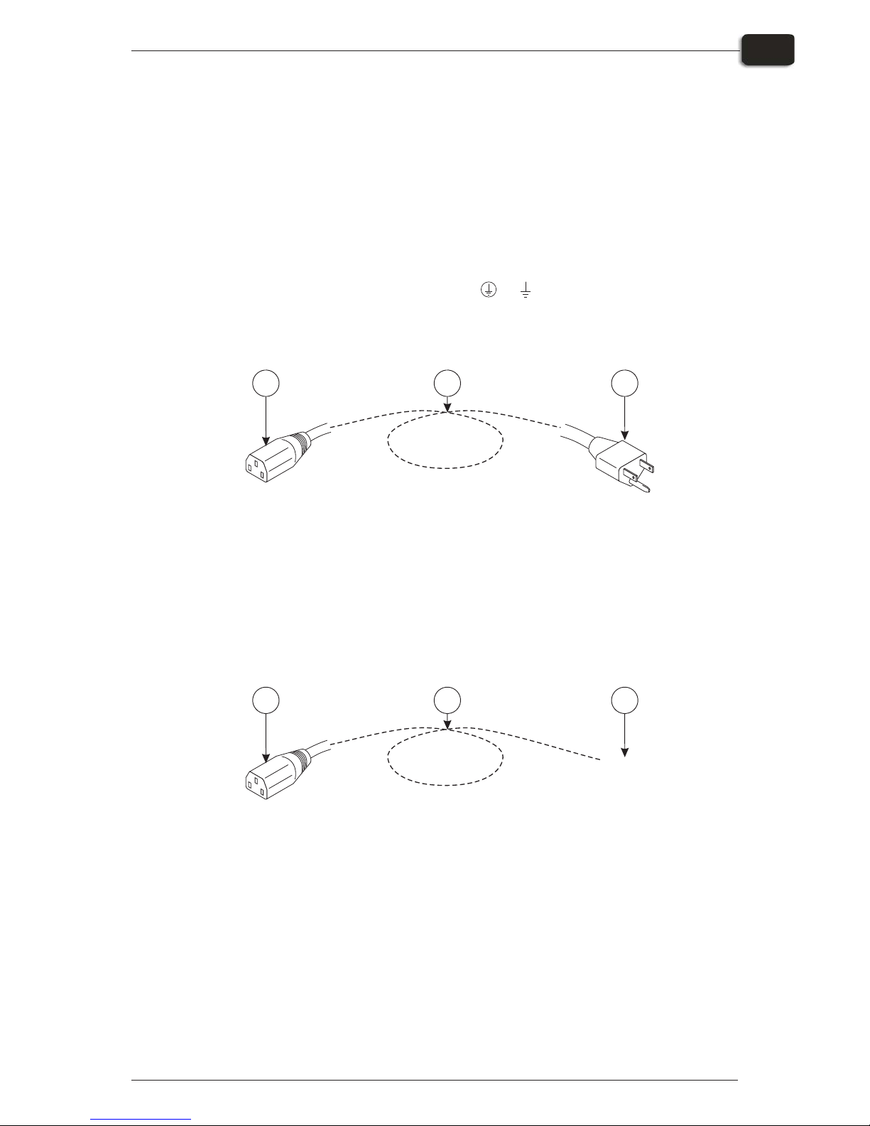
Power cables
"
The equipment is delivered with the power cables required for the
installation (USA only, outside USA these must be ordered separately).
Cables are placed in the same box as imaging unit.
If, for some reason, you decide to use cables others than the supplied, make sure that
they conform to the directions given below.
$
If you are replacing a plug, be aware that the yellow/green conductor may
only be connected to a terminal marked or .
Printer + RIP workstation (USA)
1. Appliance coupler (IEC 60320)
2. Plug type NEMA 5-15P
3. Cable min. 3 x 18 AWG, type SJT or harder service
Printer + RIP workstation (rest of world, upon order only)
1. Appliance coupler (IEC 60320)
2. Plug type may vary
3. Cable min. 3 x 18 AWG, type SJT or harder service
1434 Hardware Installation - PlateWriter™ 8000
2-3
Installation
Preparing the installation site
132
à
à
Equipment Power Outlet
T11134
132
à
à
Equipment Power Outlet
T11135
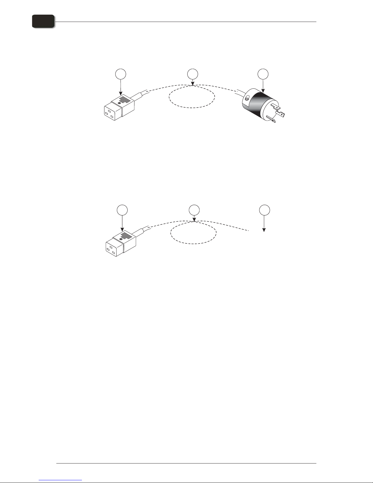
Finishing unit (USA)
1. Appliance coupler 16A (IEC 60320)
2. Plug type NEMA L6-15P, 230V AC, 15A
3. Cable min. 3 x 18 AWG, type SJT or harder service
Finishing unit (rest of world)
"
A connector plug only included with the maintenance kit when the country of
installation is specified upon order.
29759, Cable, maintenance kit, Europe
29760, Cable, maintenance kit, UK
29761, Cable, maintenance kit, Denmark
29762, Cable, maintenance kit, Italy
29763, Cable, maintenance kit, Switzerland
"
When deciding what type of cable to use, take into account the mechanical
resistance (operator may step onto cable).
The conductors in the power supply cable should be of copper.
Provide for additional cable protection, e.g., cable covers, if cable is exposed
to heavier transport such as fork-lift trucks etc.
Hardware Installation - PlateWriter™ 8000 1434
2-4
Installation
Preparing the installation site
13
à
à
Equipment Power Outlet
2
T11136
13
à
à
Equipment Power Outlet
2
T11137
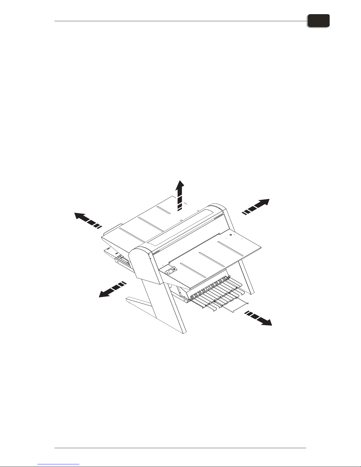
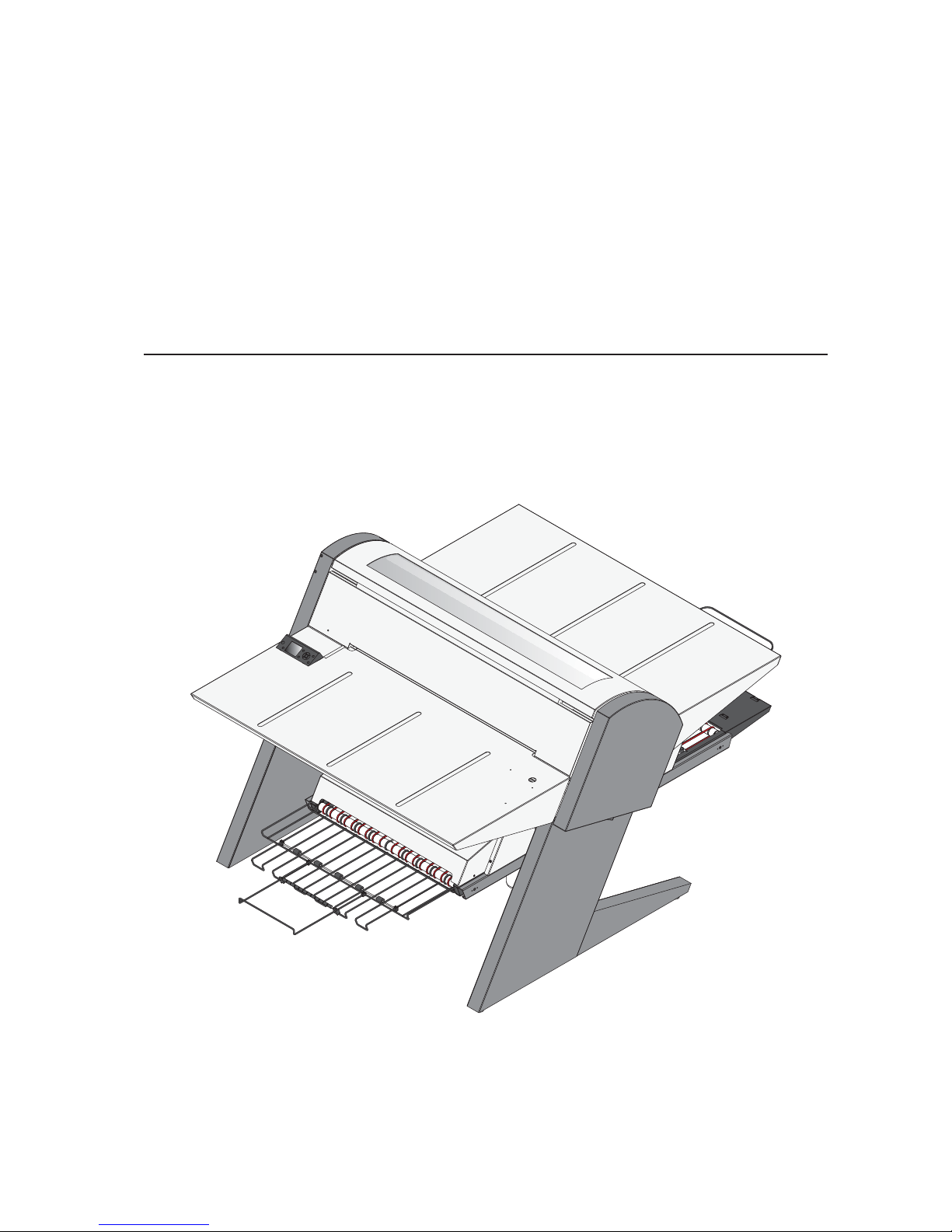
Free space around the PlateWriter
Decide where the unit shall be placed and make sure that the free space around it
makes operation and servicing possible.
Be aware of the following:
•
Liquid Dot cartridges need to be replaced on the left side of the unit.
•
Access to cables is required at the both sides of the unit.
•
Plates are loaded onto the input table from the front right of the unit.
•
After imaging the plate must be placed on the finisher unit's transport belts from the
lower front of the unit.
•
After finishing, the plate must be removed from the finisher unit’s exit tray at the
lower back of the unit.
The recommended minimum free space around the machine is specified in the
illustration below:
1434 Hardware Installation - PlateWriter™ 8000
2-5
Installation
Preparing the installation site
T32271
1m (3 ft.)
0.6 - 1m (2 - 3 ft)
1.8.m (6 ft)
1m (3 ft)
1.4 - 1.8m (5 - 6 ft)
 Loading...