

Glunz & Jensen PlateWriter 2500, PlateWriter 3000 Operating Manual

Operating Manual
PlateWriter™ 2500/3000

Operating Manual
PlateWriter™ 2500/3000
Edition CE, December 2013
This book has part No 10055648
T11296

This manual is published by: GLUNZ & JENSEN A/S
Selandia Park 1
DK-4100 Ringsted
Denmark
Phone:+45 57 68 81 81
E-mail: gjhq@glunz-jensen.com
Internet: www.glunz-jensen.com
© 2010 Glunz & Jensen A/S. All rights reserved.
Operating Manual - PlateWriter 2500/3000 1206
0-2

Table of contents
1347 Operating Manual - PlateWriter 2500/3000
Table of contents
0-3
Part 1: Introduction .................................... 1-1
About this manual ................................................1-1
Intended use of this manual .......................................1-1
Reservations ..................................................1-1
Notes, cautions, and warnings ! .....................................1-1
Important ......................................................1-2
Unintended use of the equipment....................................1-2
Safety and use .................................................1-2
The PlateWriter system .............................................1-3
The PlateWriter System consists of: ..................................1-3
PlateWriter 2500 overview ..........................................1-4
PlateWriter 3000 overview ..........................................1-6
Part 2: Daily use ......................................2-1
Overview .......................................................2-1
Daily start-up ....................................................2-1
Making a proof...................................................2-3
Creating files for proofs ...........................................2-3
Printing a proof ................................................2-3
Making plates ...................................................2-4
Creating files for plates ...........................................2-4
Loading plates on PlateWriter 2500 ..................................2-4
Loading plates on the PlateWriter 3000 ...............................2-5
Adjusting the printer exit wheel guide .................................2-6
Imaging the plate .................................................2-7
Finishing .....................................................2-9
Daily shut-down .................................................2-10
Important notes about switching the power on and off ....................2-10
Control panel function keys .........................................2-10
Part 3: Cleaning and maintenance..........................3-1
Overview .......................................................3-1
Inks and fluids ...................................................3-2
Liquid Dot (1) .................................................3-2
Maintenance Fluid (2) ...........................................3-2
Cleaning Fluid (3) ..............................................3-2
Replacing the ink cartridges..........................................3-3
Care and handling of ink cartridges...................................3-3
Other printer cleaning tasks ..........................................3-5
General ......................................................3-5
Cleaning the printer body .........................................3-5
Cleaning the printer ink system .....................................3-6

Operating Manual - PlateWriter 2500/3000 1350
Table of contents
0-4
Additional printer settings and check .................................3-9
Finishing unit ....................................................3-9
Running the gum rinse program .....................................3-9
Cleaning of gum/finisher rollers ....................................3-10
Cleaning the finishing unit body ....................................3-10
Gum/water replenishing system ....................................3-11
Part 4: Using the RIP................................... 4-1
Overview of the Navigator RIP ........................................4-1
Input formats..................................................4-1
Basic concepts and definitions ........................................4-2
Setting up devices ................................................4-4
Creating separation and progressive styles ................................4-4
Separation styles ...............................................4-4
Creating Page Setups for platemaking ...................................4-8
About Page Setups ..............................................4-8
Predefined Page Setups ..........................................4-8
Creating Page Setups ............................................4-9
PlateWriter plug-in functionality ......................................4-12
Output .....................................................4-12
Margins.....................................................4-13
Maintenance .................................................4-13
Imaging Options...............................................4-13
Imaging mode ................................................4-15
Print head row selection .........................................4-17
Screening Linearisation Control ....................................4-18
Saving the page setup...........................................4-20
Setting the plate size ...........................................4-22
Setting the Gripper and Job Position on the plate ........................4-23
Duplicating and editing existing Page Setups ...........................4-30
Printing a job using the RIP .........................................4-34
Using the Print File command .....................................4-34
Printing several files ............................................4-35
Automating job input to the RIP ......................................4-36
Printing using managed Input Plug-ins or 'Input Queues' ...................4-36
Managing Input Plugins .........................................4-37
Turning on the input system ......................................4-38
Adding a new input source to the list ................................4-38
Copying an input plugin .........................................4-39
Editing the details for an input source................................4-39
Configuring an input plugin .......................................4-40
Deleting an input source .........................................4-40
Enabling and disabling input sources ................................4-40
Using the SpoolFolder input folder ....................................4-41
Creating and configuring a SpoolFolder input source......................4-42
Using more than one method......................................4-47
Enhanced
file management and printing for Mac users ....................4-47

1350 Operating Manual - PlateWriter 2500/3000
Table of contents
0-5
Calibrating .....................................................4-48
Why calibrate ................................................4-48
Calibrating your press ...........................................4-48
Including the press calibration in Page Setups ..........................4-53
Why use Intended Press or Tone Curves? ...............................4-54
Including the Intended Press curves in Page Setups ......................4-54
Backup & restore your Navigator RIP configuration for Windows ...............4-55
Configuration backup ...........................................4-55
How to restore your configuration...................................4-55
Part 5: Troubleshooting ................................. 5-1
General ........................................................5-1
Problems with the finishing unit .......................................5-2
Indicator status and error codes .....................................5-2
Problems with the registration system/print head ...........................5-3
Indicator status and error codes .....................................5-3

Operating Manual - PlateWriter 2500/3000 1347
Table of contents
0-6

Part 1: Introduction
About this manual
Intended use of this manual
•
This manual describes the common use procedures of the PlateWriter system. It is
intended for the daily user and should be kept with the equipment for reference at
all times.
"
Printer-specific information relating to operation, maintenance and service can
be found in the manuals supplied on the CD with your printer.
Reservations
•
This manual was written and illustrated using the best possible information available at the time of publication.
•
Any differences between this manual and the equipment reflect improvements introduced after the publication of the manual.
•
Changes, technical inaccuracies and typographical errors will be corrected in subsequent editions.
•
As a part of our policy of continuous improvement, we reserve the right to alter design and specifications without further notice.
Notes, cautions, and warnings !
Throughout the manual notes, cautions, and warnings are written in bold like the
example below:
$
Always replace a fuse with one of the same size and rating as the old one.
Symbol Meaning Explanation
"
Note
The operator should observe and/or act according to the
information in order to obtain the best possible function of
the equipment.
$
Caution
The operator must observe and/or act according to the
information in order to avoid any mechanical or electrical
damage to the equipment.
#
Warning
The operator must observe and/or act according to the
information in order to avoid any personal injury.
1206 Operating Manual - PlateWriter 2500/3000
Introduction
1-1
About this manual

Important
Unintended use of the equipment
Glunz & Jensen A/S do not take any responsibility for any damage or accidents caused
by unintended use of the equipment:
•
As the equipment is certified by accredited test laboratory (UL International Demko
A/S) it is absolutely prohibited to make any modifications, electrical nor mechanical,
of the equipment. If however this prohibition is disregarded, Glunz & Jensen's warranty will no longer apply and the certification labels for UL, C-UL, and
CE certification of the equipment shall be removed as the certification will no longer
apply to the equipment.
Safety and use
•
Before using the equipment it is assumed that it has been properly installed and configured as described in the installation manuals delivered with the system.
•
The manufacturer cannot be held responsible for any damage caused by incorrect
use of this equipment.
Operating Manual - PlateWriter 2500/3000 1206
Introduction
1-2
Important
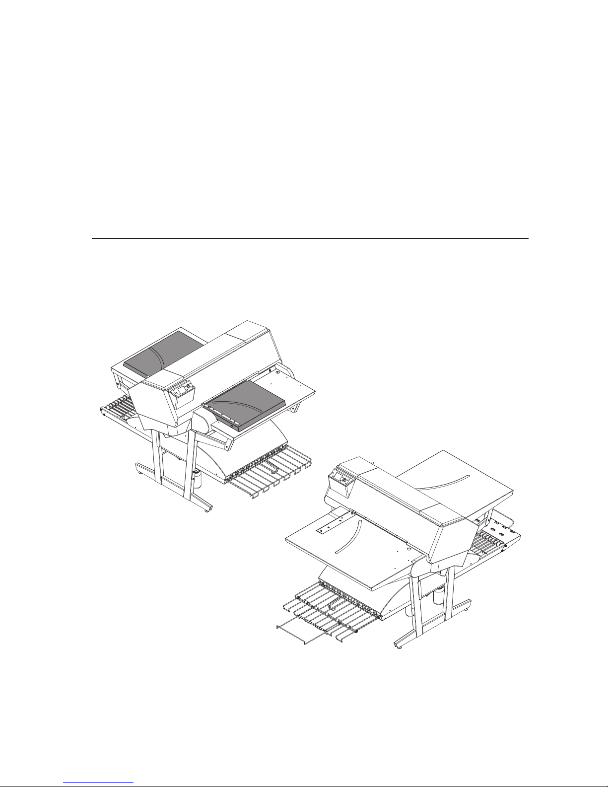
The PlateWriter system
The PlateWriter system is an innovative and patented inkjet Computer-to-Plate (iCtP)
device.
The PlateWriter System consists of:
•
PlateWriter engine (1)
A specially modified Epson inkjet printer that uses Glunz & Jensen's Liquid Dot
fluid to image the i-plates printing plates.
•
Plate input table (2)
A table for aligning plates prior to entering into the PlateWriter engine.
•
Proofer (option)
An unmodified Epson Stylus Color 4800, 4880 or 7800, 7880 printer used for proofing. Plug-ins to drive these printers are supplied with the Harlequin RIP.
•
Harlequin RIP platform
A customized workstation accessible by both Mac and PC computers, loaded with
the Global Graphics Harlequin RIP.
The Harlequin RIP provided is customized by Xitron and it accepts PostScript, PDF,
EPS, TIF & JPEG files produced by standard pre-press applications.
It RIPs the data and sends output to the PlateWriter engine or to the Proofer.
•
PlateWriter finishing unit (3)
An integrated plate finisher that executes all of the steps necessary to produce
press-ready plates, e. g.: curing, gumming and drying of the plates after they are imaged in the PlateWriter engine.
1206 Operating Manual - PlateWriter 2500/3000
Introduction
1-3
The PlateWriter system
T11312
3
2
1
3
2
1

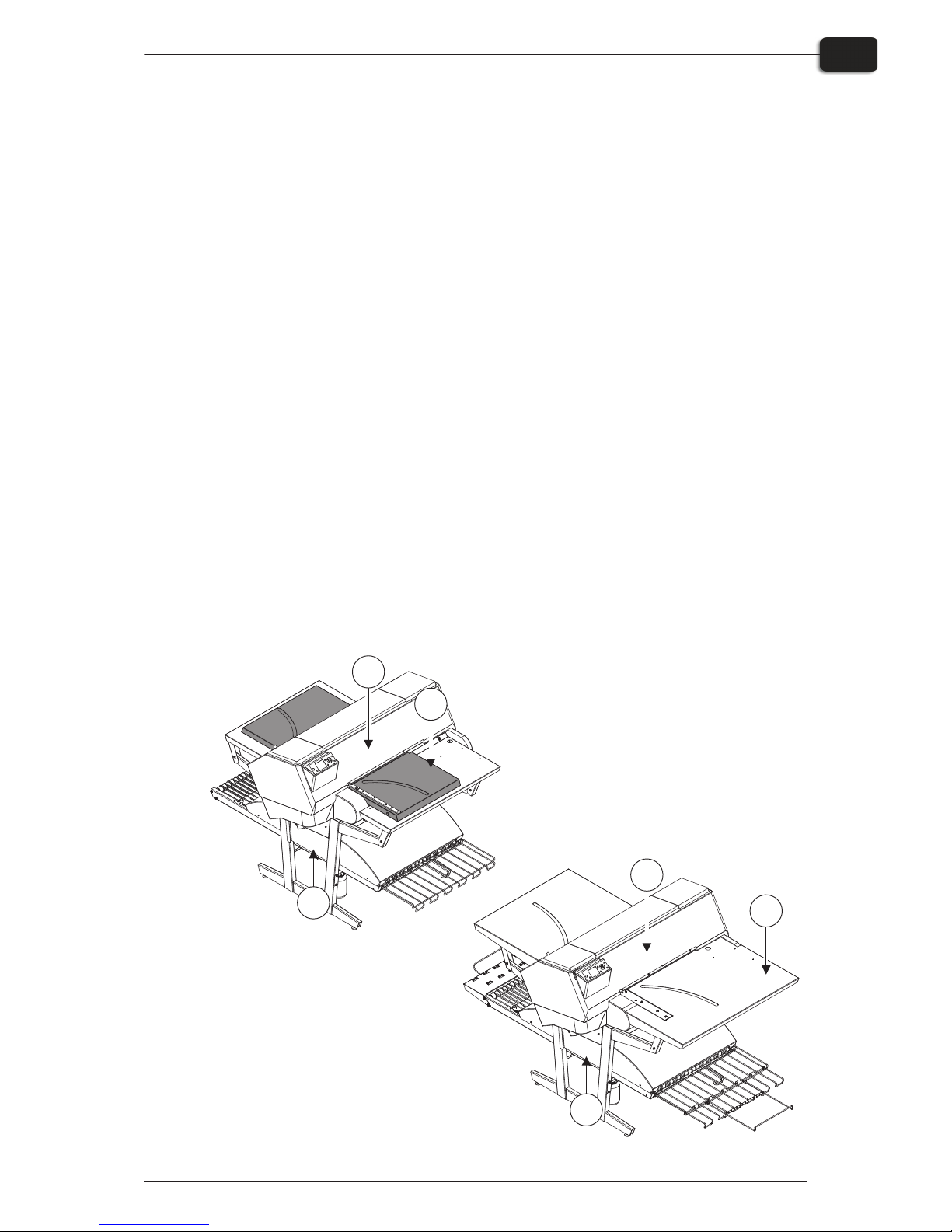
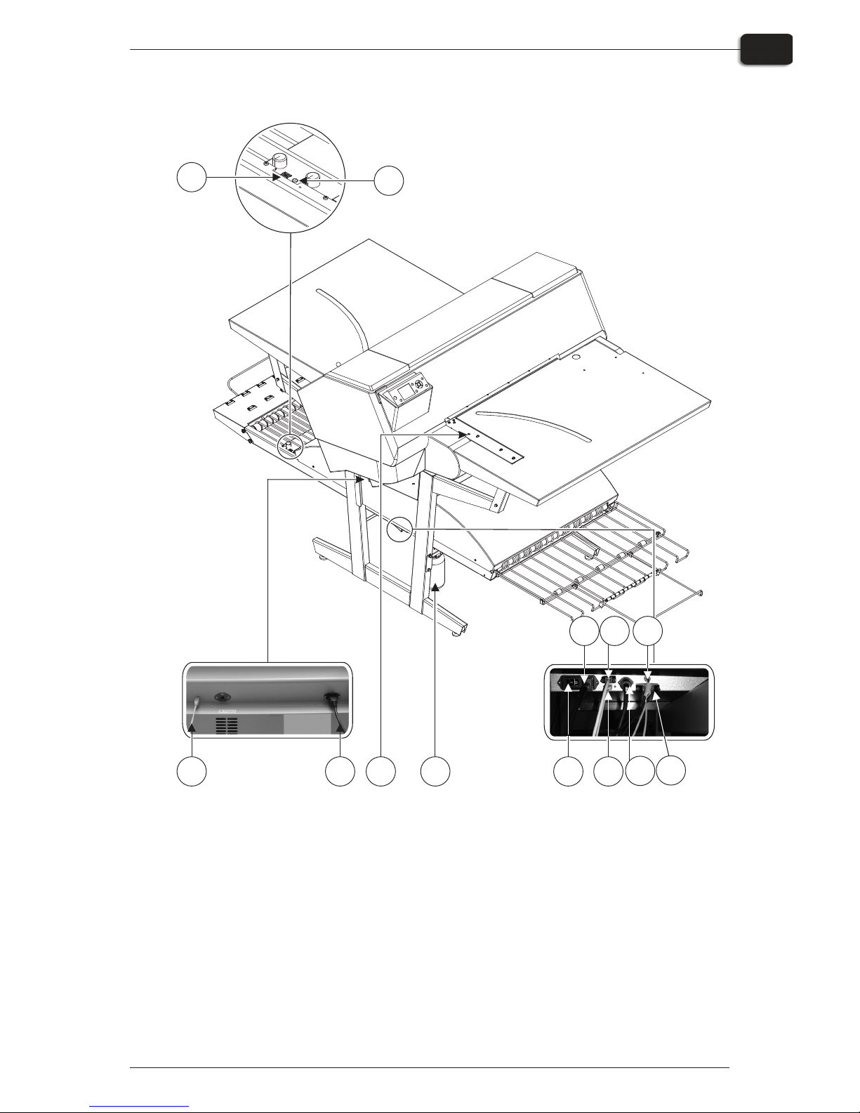
PlateWriter 2500 overview
1 Control panel: from here you control the imaging unit.
2 Input table: ensures that plates are aligned correctly prior to entering the imaging unit.
3 Exit table.
4 Curing conveyor: leads the printed plate through the curing sections.
5 Curing oven: dries the ink on the plate and cross-links it to the aluminum base.
6 Gum/finishing bottle: contains the finishing solution applied to the plate in the finishing
section. Solution not accepted by the plate returns into the bottle.
7 Finishing section: cools the plate and applies a combined gum- and plate enhancer to the
plate to protect it from oxidation and to improve its press characteristics and hydrophilic
properties when on press.
8 Gum dryer: dries the plate to provide a finished, dry plate.
9 Plate exit tray: holds the finished plates.
10 Ink cartridges: the compartment contains 5 cartridges.
11 Water bottle: contains demineralised water for replenish of the gum.
Operating Manual - PlateWriter 2500/3000 1206
Introduction
1-4
PlateWriter 2500 overview
T11298
89
1
7
5
4
10
6
11
2
3
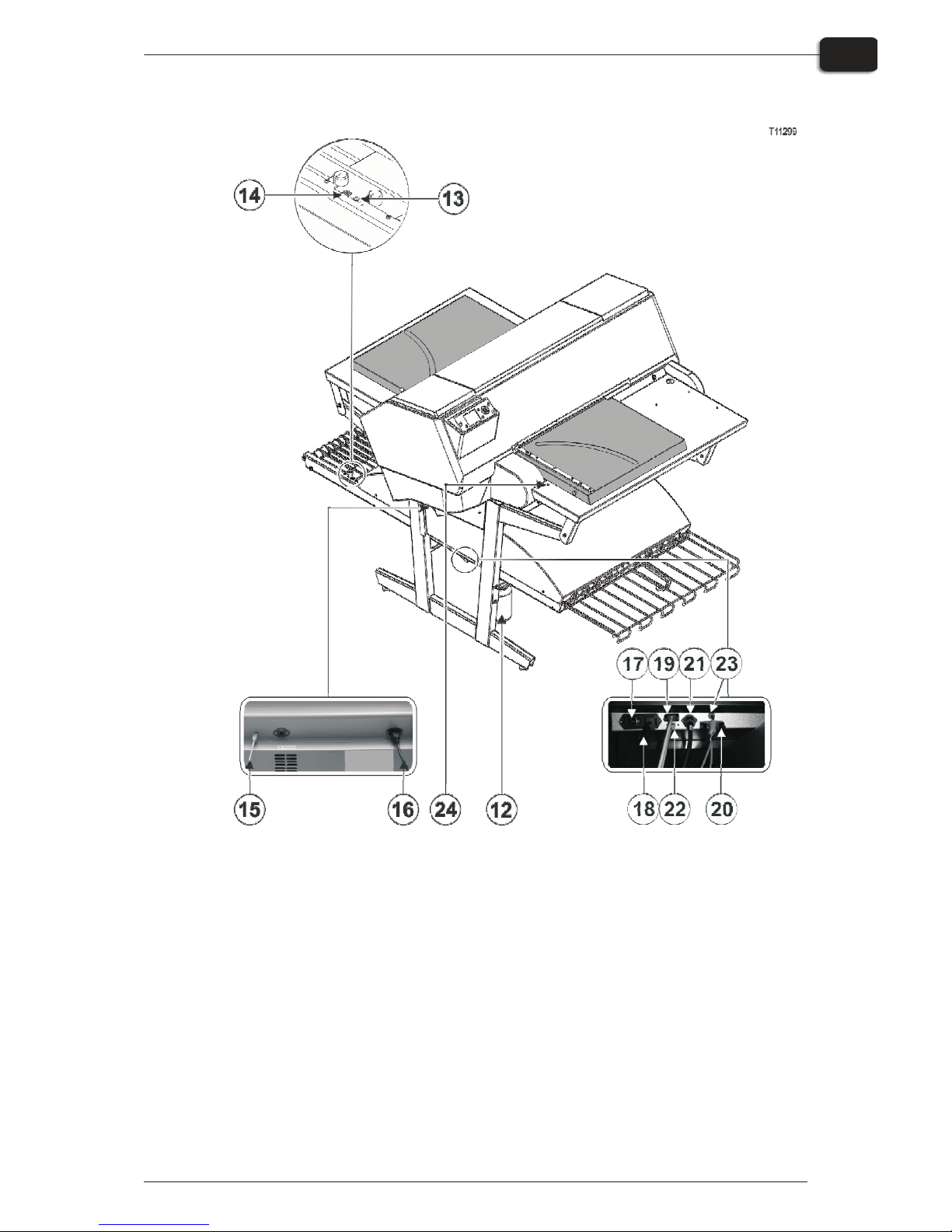
12 Waste ink bottle.
13 Status indicator LED: indicates the current status of the finishing unit.
14 Program selector: for selection of the curing oven program.
15 USB-cable: connects the imaging unit with the RIP workstation.
16 Power cable: supply voltage for the imaging unit.
17 Power switch: press here to switch the finishing unit on/off.
18 Power cable: supply voltage for the finishing unit.
19 Control cable: connects the print bed heaters with the finishing unit.
20 Power cable: supply voltage from finishing unit to the print bed heaters.
21 Control cable: connects the input table LED with the finishing unit.
22 USB-cable: connects the finishing unit with the RIP workstation.
23 Control cable: connects the print head protection with the finishing unit.
24 Status indicator LED: indicates the alignment of the plates and the temperature deviation
of the print bed.
1350 Operating Manual - PlateWriter 2500/3000
Introduction
1-5
PlateWriter 2500 overview
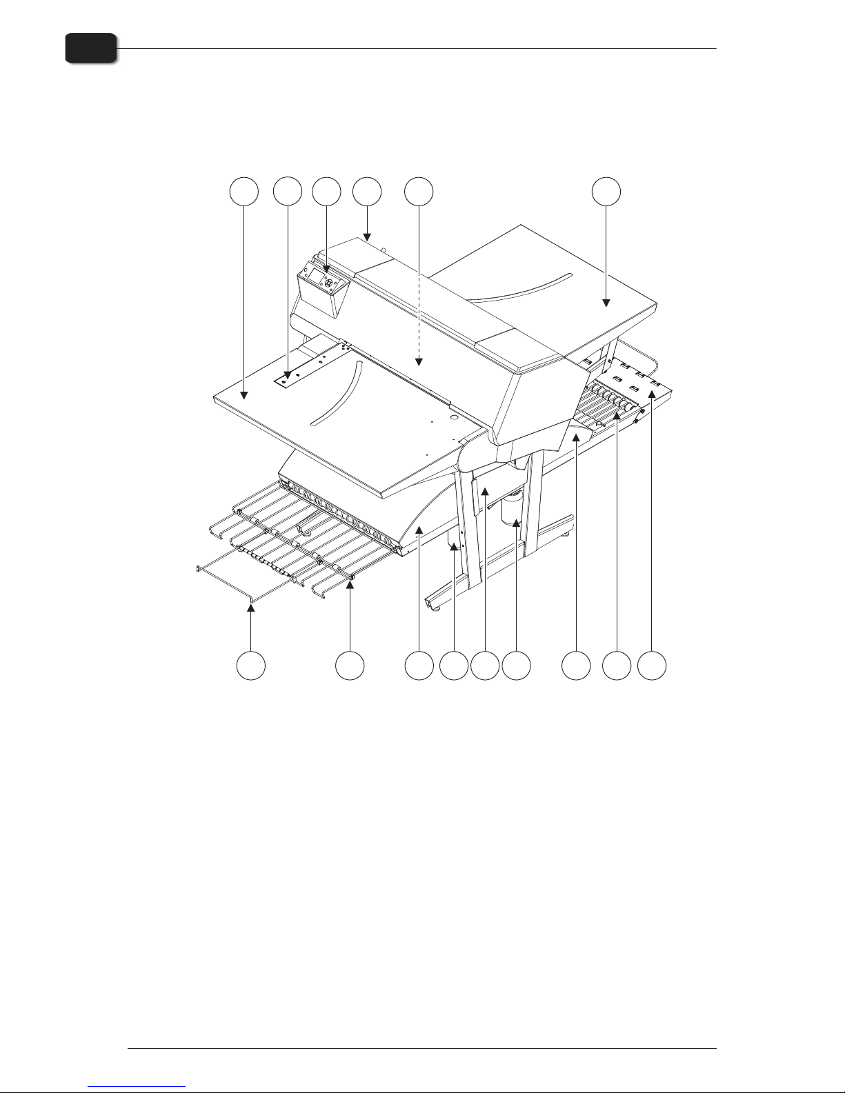
PlateWriter 3000 overview
1 Control panel: from here you control the imaging unit.
2 Input table.
3 Exit table.
4 Curing conveyor: leads the printed plate through the curing sections.
5 Curing oven: dries the ink on the plate and cross-links it to the aluminum base.
6 Gum/finishing bottle: contains the finishing solution applied to the plate in the finishing
section. Solution not accepted by the plate returns into the bottle.
7 Finishing section: cools the plate and applies a combined gum- and plate enhancer to the
plate to protect it from oxidation and to improve its press characteristics and hydrophilic
properties when on press.
8 Gum dryer: dries the plate to provide a finished, dry plate.
9 Plate exit tray: holds the finished plates.
10 Ink cartridges: the compartment contains 5 cartridges.
11 Water bottle: contains demineralised water for replenish of the gum.
12 Short finisher extension.
13 Side register: ensures that plates are aligned correctly prior to entering the imaging unit.
14 Front register: ensures that plates are aligned correctly prior to entering the imaging unit.
15 Exit tray extension.
Operating Manual - PlateWriter 2500/3000 1206
Introduction
1-6
PlateWriter 3000 overview
T11240
89
12
1
3
2
13
7
5
4
10
6
11
14
15
16 Waste ink bottle.
17 Status indicator LED: indicates the current status of the finishing unit.
18 Program selector: for selection of the curing oven program.
19 USB-cable: connects the imaging unit with the RIP workstation.
20 Power cable: supply voltage for the imaging unit.
21 Power switch: press here to switch the finishing unit on/off.
22 Power cable: supply voltage for the finishing unit.
23 Control cable: connects the print bed heaters with the finishing unit.
24 Power cable: supply voltage from finishing unit to the print bed heaters.
25 Control cable: connects the front and side register with the finishing unit.
26 USB-cable: connects the finishing unit with the RIP workstation.
27 Control cable: connects the print head protection with finishing unit.
28 Status indicator LED: indicates the alignment of the plates and the temperature deviation
of the print bed.
1350 Operating Manual - PlateWriter 2500/3000
Introduction
1-7
PlateWriter 3000 overview
T11239
16
17
18
19
20
28
21
24
26
23
22 25
27

Operating Manual - PlateWriter 2500/3000 1206
Introduction
1-8
PlateWriter 3000 overview
Part 2: Daily use
Overview
The daily use procedures described in this chapter cover the following issues:
•
Daily start-up procedure
•
Loading of plates into the PlateWriter for printing
•
Printing of plates
•
Finishing
•
Daily shut-down procedure
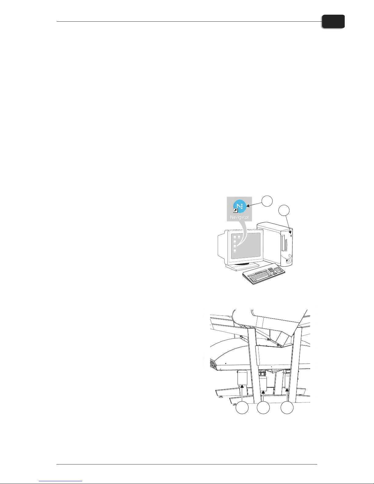
Daily start-up
•
Start the RIP workstation (1).
•
Launch the RIP application (2).
•
Replace the finisher solution in the finishing bottle (3) with fresh finisher solution.
"
Half a bottle is sufficient.
•
Empty the waste ink bottle (4) if it is full.
•
Refill the water bottle (5) with demineralised water if it is empty.
1206 Operating Manual - PlateWriter 2500/3000
Daily use
2-1
Overview
1
2
T11250
T11241
3
4
5
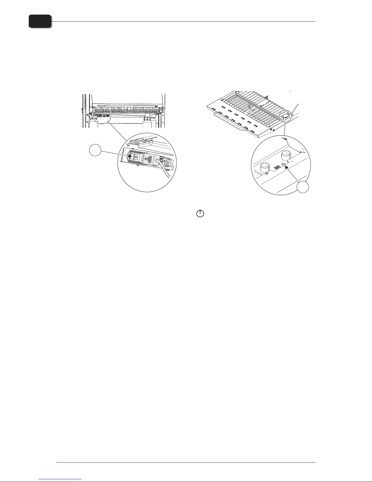
•
Switch on the finishing unit on the main switch (6) underneath and make sure that
the indicator (7) lights steady green.
•
The unit will run gum fluid through the system for approximately three minutes to
ensure an even gumming of the plates.
•
Switch on the PlateWriter by pressing the button.
•
The PlateWriter initializes and when finished, the display shows ”READY”.
Operating Manual - PlateWriter 2500/3000 1206
Daily use
2-2
Daily start-up
T11243
6
T11244
7

Making a proof
Creating files for proofs
•
Use your DTP application to prepare a composite output file - please refer to your
application manual for help.
Select an output page size sufficiently large to accommodate your content and any
registration marks or colour bars.
•
Save the file to a folder, either on the computer running Navigator RIP or on a
server.
Printing a proof
•
In the Navigator RIP open the Output Controller / Monitor window by either
pressing Ctrl+O or choosing Output -> Output Controller from the RIP menu.
•
Be sure that Disable Output is checked.
•
Select Navigator -> Print file from the RIP menu.
Choose an appropriate Proofing Page Setup and a file type (.ps, .pdf, .eps, .jpg or .tif)
from the dialogue.
Navigate to the folder containing your composite files, choose one file, and click on
Print.
•
The file will be ripped and will appear in the Active Queue of the Output Moni-
tor/Controller window.
•
Uncheck Disable Output in the Output Controller/Monitor window. The proof will
be printed.
1206 Operating Manual - PlateWriter 2500/3000
Daily use
2-3
Making a proof
Making plates
Creating files for plates
•
Use your DTP application to prepare separation output files - please refer to your
application manual for help.
•
Select an output page size sufficiently large to accommodate your content and any
registration marks or colour bars - it should not be the same size as your plate. The
RIP will position a smaller page correctly on your plate for you.
•
Save the file to a folder, either on the computer running Navigator RIP or on a server.
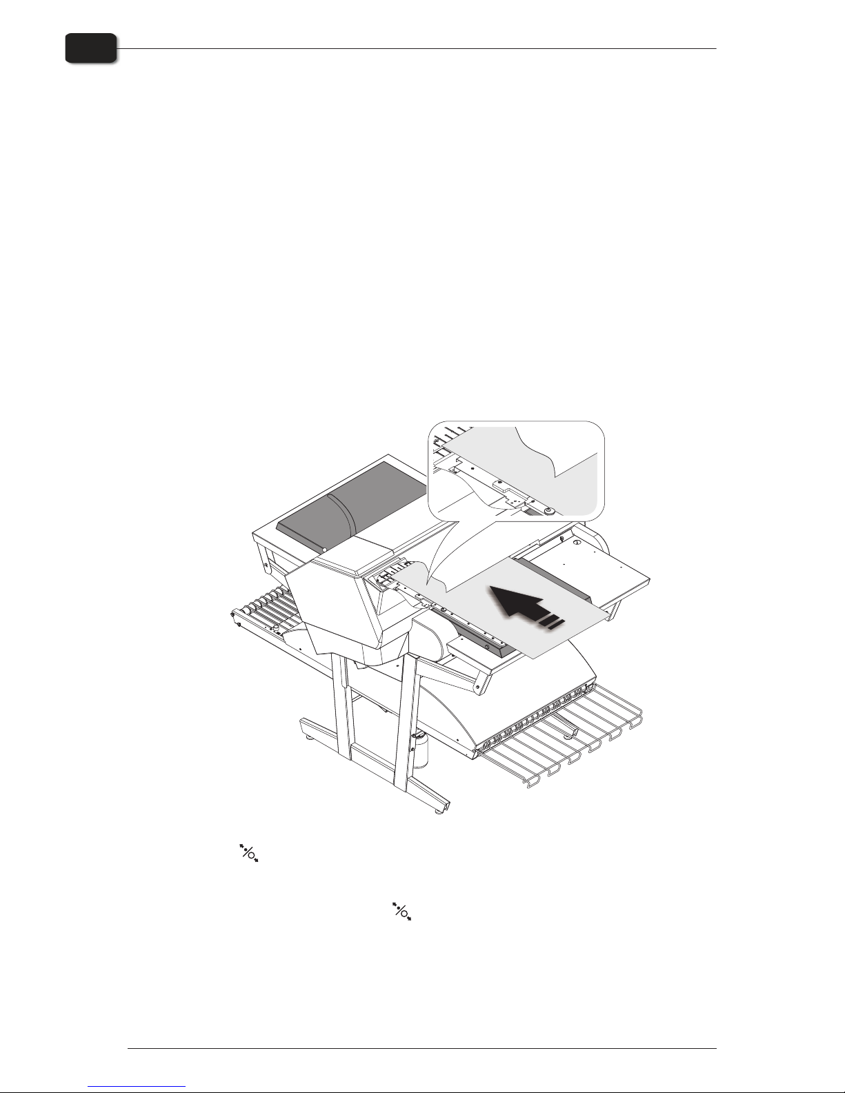
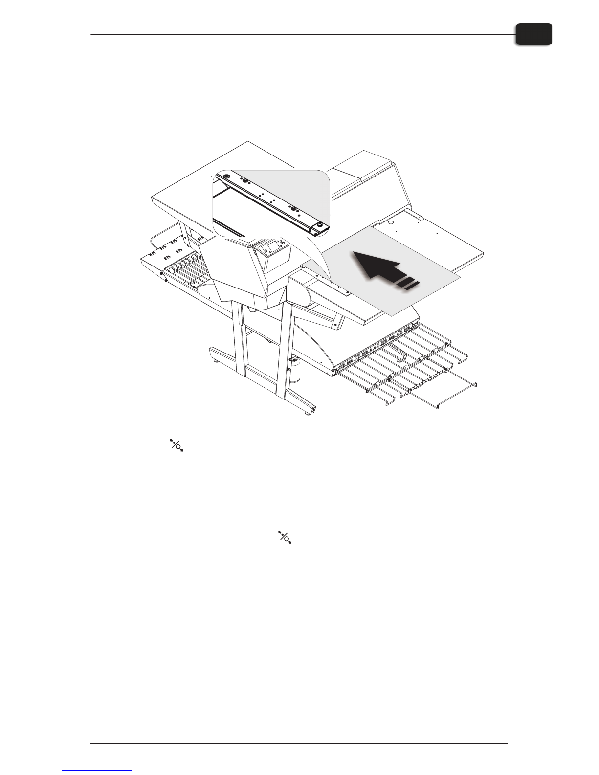
Loading plates on PlateWriter 2500
The input table ensures that plates are fed into the printer correctly. The side register
rollers enable correct and easy alignment prior to entering the printer.
•
Press the button, place the plate on the input table against the register rollers on
the left side and slide the plate into the printer, until plate reaches beyond the
groove in the print bed.
•
When LED lights green, press the button and plate will enter the printer automatically.
"
LED flashes green even before the plate is inserted. This indicates deviation in
temperature on the print bed. When less than 3 flashes, then the temperature is
ready to image plates.
Operating Manual - PlateWriter 2500/3000 1206
Daily use
2-4
Making plates
T11300
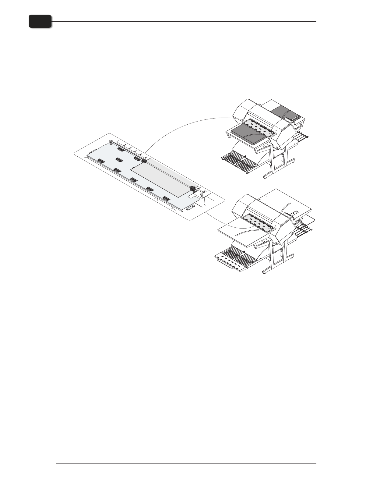
Loading plates on the PlateWriter 3000
The input table ensures that plates are fed into the printer correctly. The front and side
register pins enable correct and easy alignment prior to entering the printer.
•
Press the button, place the plate on the input table against the register pins on the
left side and slide the plate into the printer, until plate reach the front register pins.
•
Align the plate according to the side or front register pins. Observe the LED control
of the side register. If LED:
– lights green - the plate is placed according to side OR front register pins - correctly,
– lights red - the plate is placed according to side AND front register pins - incorrectly,
– is off - the plate is not placed according to side NOR front register pins - incorrectly.
•
When LED lights green, press the button and plate will enter the printer automatically. If LED lights red or is off, repeat the procedure again.
"
LED flashes green even before the plate is inserted. This indicates deviation in
temperature on the print bed. When less than 3 flashes, then the temperature is
ready to image plates.
1206 Operating Manual - PlateWriter 2500/3000
Daily use
2-5
Making plates
T11245
Adjusting the printer exit wheel guide
The printer exit wheel guide prevents the plates from raising upwards, and to avoid
the risk of crash and damage the print head.
•
Press the button and slide the rollers to make it fit the edges of the plate.
"
Remember to adjust the printer exit wheel guide every time the plate size is
changed.
Operating Manual - PlateWriter 2500/3000 1206
Daily use
2-6
Making plates
T11314
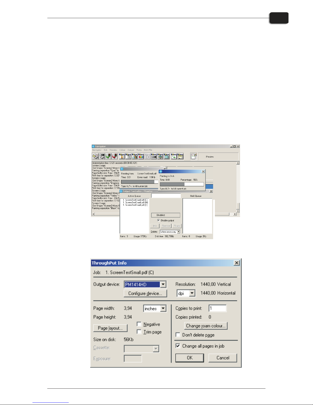
Imaging the plate
•
In the Navigator RIP open the Output Controller / Monitor window by either
pressing Ctrl+O or choosing Output -> Output Controller from the RIP menu.
•
Be sure that Disable Output is checked.
•
Select Navigator -> Print file from the RIP menu.
Choose an appropriate PlateWriter Page Setup that matches your print job and the
orientation of the loaded plate, then choose a file type (.ps, .pdf, .eps, .jpg or .tif).
Navigate to the folder containing your separation files, choose the files, and click on
Print.
•
The files will be ripped and will appear in the Active Queue of the Output Moni-
tor/Controller window.
•
The ink (colour) of each separation will be displayed in brackets after the job name,
and if there are multiple pages, then each page will be designated with a numeric
value.
•
Select your file and click on Info.
•
The ThroughPut Info window appears.
•
Be sure that Change all pages in job is checked.
1350 Operating Manual - PlateWriter 2500/3000
Daily use
2-7
Imaging the plate
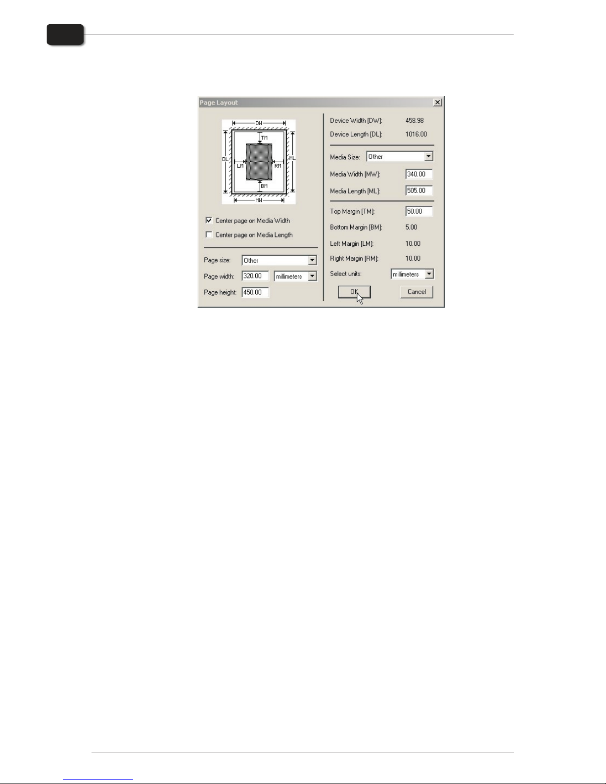
•
Click on Page layout... to open the Page Layout window.
•
Check that the size of your plate is correctly entered in the Media Width [MW] and
Media Length [ML] boxes. Most plates will be imaged landscape in the PlateWriter.
Depending on whether you are loading the plates in portrait or landscape and
whether you have a portrait or landscape press, different selection to select the Cen-
ter page on Media Length and set the Left Margins have to be made. If you load the
plate in portrait and have a landscape press, be sure [LM] to accommodate the normal unprintable area on your press. (also known as the Grip).
•
If you have a portrait press, and have loaded the plate portrait, then make sure to select the Center page on Media Width and set the Top Margin [TM] to accommodate the normal unprintable area on your press.
•
Click OK in the Page Layout window and in the ThroughPut Info window.
•
Drag all but the first separation of your job to the Held Queue.
•
Uncheck Disable Output in the Output Controller/Monitor window. The first plate
will be printed.
•
Remove the plate from the PlateWriter and place it on the front of the PlateWriter
finishing unit, see finishing procedure in the following section.
•
For subsequent plates, make sure that Disable Output is checked, load a plate into
the PlateWriter, drag one separation from the Held Queue to the Active Queue, and
then uncheck Disable Output.
Operating Manual - PlateWriter 2500/3000 1206
Daily use
2-8
Imaging the plate
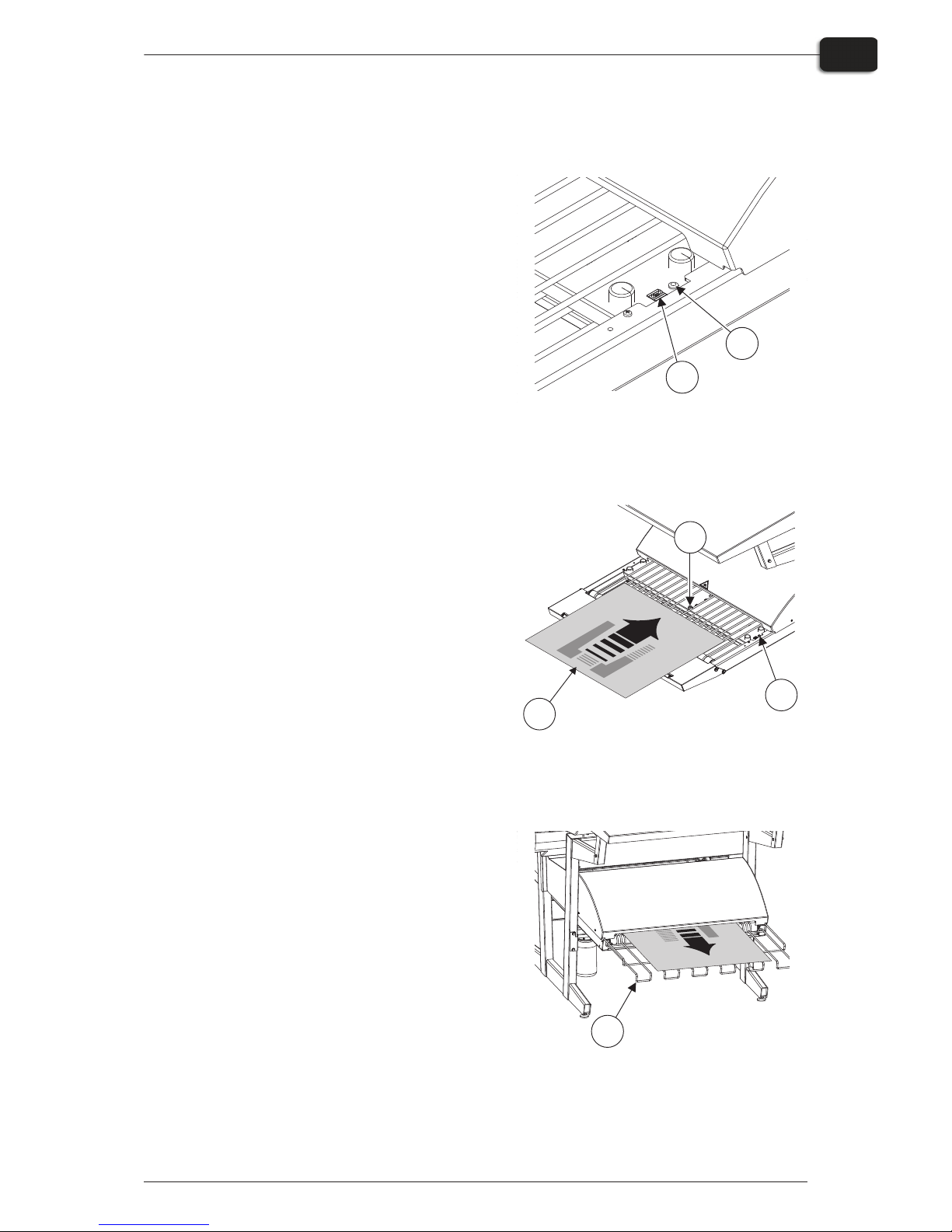
Finishing
•
Use +/- buttons on the program selector
(1) to select program:
1 = 0.15 mm plates
2 = 0.20 mm plates
3 = 0.30 mm plates
4 = Gumming only/gum rinse
"
Program 0 is for technicians only!
•
Make sure that the indicator (2) lights
steady green.
"
For the various indicator status and
error codes please see Part 5 “Troubleshooting”.
•
Place the printed plate (3) on the conveyor making sure that the front edge is
placed over the plate sensor (4).
•
If the curing oven has already reached
the correct working temperature, the conveyor will take the plate through the
oven, otherwise it moves the plate
slightly forward and then it stops until
the oven is ready.
•
While the indicator (5) lights steady
green or flashing green, plates can be put
on the conveyor if the program selector is
not changed. Program selector can be
changed only when the indicator lights
steady green.
"
Recommended distance between two
consecutive plates is at least 50 mm.
It is important that the plates are not
pushed forward by hand into the
oven.
"
It is recommended to make a space
of at least 300 mm or approx. two
minutes between every 4-8 plates in
order for the gum replenish system
to work properly.
•
When the plate is cured and finished then
it appears on the exit tray (6).
1206 Operating Manual - PlateWriter 2500/3000
Daily use
2-9
Imaging the plate
2
T11246
1
T11247
3
4
5
T11248
6
Daily shut-down
•
Switch the unit into OFF-mode by pressing key. All lights turn off and the display will go blank.
Important notes about switching the power on and off
Never switch off the main power while the printer is running. The printing heads may
be left uncapped. If the machine is left unused with the printing heads uncapped for a
prolonged period, the printing heads may become irreversibly clogged.
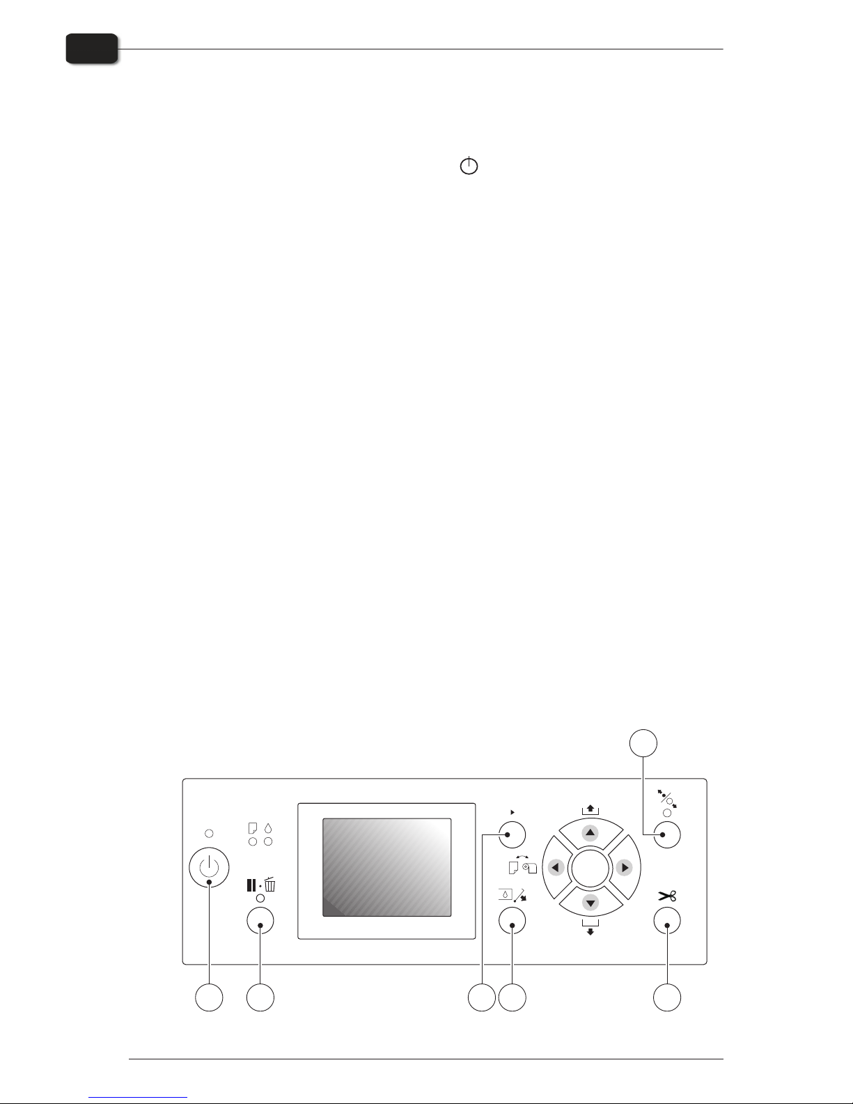
Control panel function keys
The PlateWriter is equipped with the function keys located on the control panel.
(1) Power button - turns the printer on/off.
(2) Pause/reset button - the printer enters the pause state, when this button is pressed
in READY mode. When selecting JOB CANCEL, it functions as the reset button. This
buttons clears errors, when it is possible.
(3) Cleaning button - performs the normal cleaning for the print head (all colours). If
you notice the print quality has declined, this will improve the print quality.
(4) Ink cover button - slightly opens the ink cover, selecting OPEN RIGHT COVER
indicated on the display.
(5) Cut button - make sure that this is set to the sheet mode. Otherwise the roll mode
or roll mode with cutter will not work.
(6) Secure button - this button is used to activate the registration system. Use this
button to load and release the plate.
Operating Manual - PlateWriter 2500/3000 1347
Daily use
2-10
Daily shut-down
Check
OK
Menu
AA
1 2
3
4
5
6

Part 3: Cleaning and maintenance
Overview
This section describes the various procedures for care and maintenance such as:
Printer
•
Cleaning the printer body
•
Cleaning the printer ink system
•
Additional printer settings and check
Finishing unit
•
Topping up the gum/finisher solution (daily)
•
Replacing the gum/finisher solution (weekly)
•
Running the gum rinse program (weekly)
•
Cleaning of the gum/finisher rollers (monthly)
For more information about cleaning and maintenance see the Maintenance Chart.
1206 Operating Manual - PlateWriter 2500/3000
Cleaning and maintenance
3-1
Overview
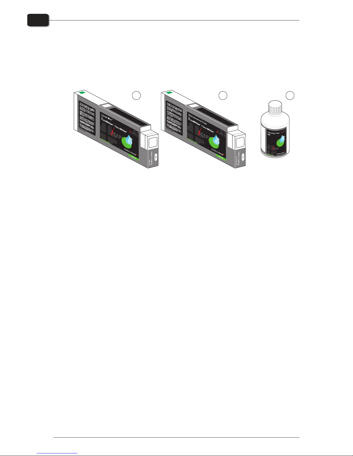
Inks and fluids
The PlateWriter requires the use of various inks and fluids for processing, cleaning and
maintenance purposes:
Liquid Dot (1)
The Liquid Dot ink is supplied in special cartridges and used in the imaging channels
to create a hydrophobic image on the printing plate.
Maintenance Fluid (2)
The Maintenance Fluid is a general purpose fluid supplied in special cartridges, and is
used to help keeping the ink system clean.
Cleaning Fluid (3)
The Cleaning Fluid is supplied in a small bottle, and is used together with a cleaning
stick to wipe around the print head, wiper and head cap seal, to remove dried out ink.
The Cleaning Fluid is also used for dripping in and wetting the head cap to prevent the
ink from drying out the ink pump system.
Operating Manual - PlateWriter 2500/3000 1206
Cleaning and maintenance
3-2
Inks and fluids
T11258
1 2
Manufacturedby:
Haslevvej13
DK-4100 Ringsted
Denmark
GLUNZ&JENSEN A/S
Tel.+4557 688181
Fax+4557688340
E-mail:gjhq@glunz-jensen.com
Internet:www.glunz-jensen.com
Manufacturedby:
Haslevvej13
DK-4100 Ringsted
Denmark
GLUNZ&JENSEN A/S
Tel.+4557688181
Fax+4557688340
E-mail:gjhq@glunz-jensen.com
Internet:www.glunz-jensen.com
3

Replacing the ink cartridges
If ink runs out, replace the cartridges as described in the following.
$
Never use any ink other than genuine Liquid Dot ink from Glunz & Jensen.
Doing so may result in malfunction or faulty operation.
Care and handling of ink cartridges
Give attention to the following points when handling ink cartridges.
•
Never attempt to install any ink other than a Liquid Dot cartridge.
•
Never attempt to disassemble.
•
Never drop or allow to fall. The impact from a fall may cause damage, making the
cartridge unusable.
•
Store unopened in a well-ventilated location where the temperature is from 5ºC (41ºF)
to 40ºC (104ºF).
•
Once an ink cartridge has been installed, never remove it until the ink has been used
up, except when moving the machine or when Liquid Dot cartridges must be moved
to a new slot.
Frequent insertion and removal may cause air to enter the ink tube, resulting in dot
drop-out or other problems in printing quality.
•
After removing an ink cartridge, never allow the machine to stand with the ink-cartridge port remaining empty — install a new ink cartridge immediately. Failure to
do so may result in clogging of the heads.
•
Liquid Dot and Maintenance Fluid cartridges can be inserted and used in any
desired slot and in any combination. However if Liquid Dot cartridges are moved to
a slot that previously had Maintenance Fluid charged, then a new ink charge
sequence has to be conducted.
•
Maintenance Fluid can be moved to a slot that previously had Liquid Dot charged
without problems. Note however that the Liquid Dot in the printer will be quickly
‘contaminated’ by Maintenance Fluid and therefore cannot be used for imaging.
•
If the printer has not been charged previously, i.e if the printer is new and/or the
ink system is flushed and clean, it is recommended to use the following slots for
Liquid Dot in prioritized order: Pk/Y, Mk/Pk, Mk/Y, C/M channels.
"
It is also recommended to use Liquid Dot in three channels, preferred option is
Mk/Pk/Y. Three channels will provide higher flexibility, but remember to
configure the use of the channels in the RIP plug-in.
"
Read carefully the text on the cartridges for any warning regarding
compatibility with other Liquid Dot ink or Maintenance Fluid types.
•
If Liquid Dot Cartridges are moved to a new slot that was previously charged with
Maintenance Fluid, then carry out an ink charge as described below.
•
The ink charge procedure is conducted in order for moving Liquid Dot through the
ink system and into the print head.
Only if clear Maintenance Fluid has been previously charged is it possible to
visually control that Liquid Dot has replaced the Maintenance Fluid. Otherwise it is
recommended to use a small scale with an accuracy of approximately 1 gram.
Cartridges can then be weighed before and after the ink charge giving a more
precise indication of the amount of fluid that has been charged.
1347 Operating Manual - PlateWriter 2500/3000
Cleaning and maintenance
3-3
Replacing the ink cartridges

1. Weigh the Liquid Dot cartridges that are to be moved.
2. Place the cartridges in the new slot positions.
3. Switch the printer off at the operator panel.
4. Press and hold the three buttons: , t and q, then switch printer on.
5. Keep the three buttons , t and qpressed until the menu is displayed.
6. Press the menu/u key.
7. Use q to scroll down and select ‘Cleaning’ with u.
8. Select the cleaning for the appropriate channels. E.g. if a Liquid Dot cartridge has
been moved to MK slot then select the ‘E/F (Mk/Mk)’ cleaning command.
9. Then select the ‘CL4’ command and press enter to start.
10.Do a CL4 clean for each other relevant channel.
11.Weight the cartridge and calculate the consumption.
12.If less than 30 gr. has been charged pr. cartridge repeat step 10 and 11. A CL4 clean
will normally charge approximately 18-20 gr.
If less than 10 gr. are consumed pr. CL4 clean, then the ink head may be clogged or the
pump cap assembly may be malfunctioning.
"
Move the small label supplied with each cartridge and place in inside the ink
cover lid. This is to mark which slots have Liquid Dot cartridges and which
has Maintenance Fluid cartridges for later reference.
Operating Manual - PlateWriter 2500/3000 1350
Cleaning and maintenance
3-4
Replacing the ink cartridges
OKOKOK
 Loading...