

R
FOX-UP
INSTALLATION AND OPERATING INSTRUCTIONS
MONTAGE- UND BEDIENUNGSANLEITUNG
INSTALLATIE- EN BEDIENINGSHANDLEIDING
INSTRUCTIONS D’INSTALLATION ET D’UTILISATION
R
Installation and operating instructions - English ...........................................................................1
Montage- und Bedienungsanleitung - Deutsch ...........................................................................27
Installatie- en bedieningshandleiding - Nederlands ..................................................................53
Instructions d’installation et d’utilisation - français .................................................................. 79
INSTALLATION AND OPERATING INSTRUCTIONS - ENGLISH
Due to an easy mounting, the units of the Fox Up series are suitable in new buildings and for refurbishment purposes. Fox Up allows for
hygienic air exchange in line with the standards. The units work as a decentralized system and are mounted completely in the outer walls.
There is no need for piping across rooms or floors nor for complex cleaning concepts.
OPERATING INSTRUCTIONS
Storing the manual
All service providers involved in mounting, connection and the set-up of the Fox up ventilators needs the information of this manual in order
to do the work correctly. Please make sure that the manual is available for them.
Please give all users a copy of this manual for consultation when the installation is delivered, it contains important notes on maintenance,
operation and maintenance.
INSTALLATION INSTRUCTIONS - CONTENTS
1. General notes ............................................................................................................................................................................................................2
2. Productinformation..................................................................................................................................................................................................3
3. Delivery units / Delivery contents ..........................................................................................................................................................................4
4. Dimensions / Technical Data ..................................................................................................................................................................................5
5. Selecting installation site ...................................................................................................................................................................................... 6
6. Installation of wall duct .......................................................................................................................................................................................... 6
7. Installation of electronic control system ............................................................................................................................................................. 8
8. Electrical connection of electronic control system / ventilation unit .............................................................................................................. 9
9. Installation ............................................................................................................................................................................................................... 11
10. Start-up report ........................................................................................................................................................................................................ 13
EN
11. Operating instructions ...........................................................................................................................................................................................14
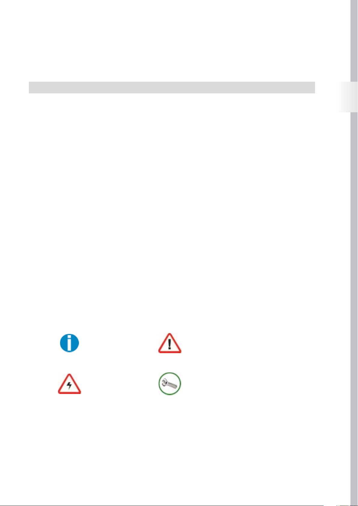
Symbols
The following symbols are used in this manual to indicate special instructions:
General note / Information
Danger due to electrical voltage Installation note / Warning
Warning
1
R
1. GENERAL NOTES
Fox up ventilation units are built in accordance with the latest technological standards and acknowledged safety regulations.
Installation and maintenance on the ventilation unit should only be carried out by specially trained personal in accordance
with the regulations on occupational safety and accident prevention.
The electrical connection must be carried out according the applicable national regulation. During installation
and maintenance work, all poles must be disconnected from the mains with a contact gap of at least 3 mm.
Disconnections must be fixed in the open position!!
The unit may only be used for its intended purpose. Improper use, installation or maintenance work carried out incorrectly and structural
modifications may affect the function and safety of the ventilation unit. In this case the warranty claims will not be valid.
Read these instructions carefully before beginning any installation or maintenance work and follow the advice given on installation and
maintenance.
Before installing the unit, check that the delivery is complete and intact, and contact us, at the address below, if any parts are missing or
damaged.
Intended use
Fox up ventilation units with heat recovery are designed for controlled room ventilation. The units should only be used to deliver air. The delivery of aggressive, flammable or dust-containing media is not permitted. Never operate the unit without the filter in place. The connection
of ventilation pipes from other ventilation systems is not permitted.
Fox up ventilation units are not suitable for construction drying, and should only be used once construction work has been finished.
Operating the unit in conjunction with heat-producing appliances may require additional safety devices. Relevant information is available
from a regionally qualified chimney sweep.
Placing the unit
Fox up ventilation units may only be installed and operated indoors. When selecting a site, please make sure that the unit is accessible for
service and maintenance. The unit must not be installed close to flammable liquids or gases. A mains supply (230 V/50 Hz) is required to
operate the unit.
Installation
When installing the unit, please observe the recognized codes of practice with regard to unit installation, electrical work, fire protection,
etc., as well as the standards for the ventilation of residential buildings.
2
2. PRODUCTINFORMATION
2.1 Mode of operation
The Fox up ventilation unit is a decentralized ventilation system for a controlled room ventilation with heat recovery. The use
of several units in pairs allows entire housing units / buildings to be ventilated.
If operated with heat recovery, the ventilation unit works in 2 prefixed time intervals. In the first interval (extraction phase),
the “used” air in the room is sucked into the ventilation unit by the fan and carried to the outside. During this process, the air flows through
the ceramic heat accumulator inside the ventilation unit, which extracts the heat from the air and stores it.
In the second interval (delivery phase), “fresh” outside air is sucked in via the ventilation unit’s exterior opening. It passes through the unit,
and is heated by the heat accumulator before entering the room. In this way, up to 90% of the heat contained in the extracted air can be
transferred to the fresh air fed into the room. The principle of recharging and discharging a heat accumulator is referred as regenerative
heat transfer.
When a single unit is used, an overpressure (delivery phase) or under pressure (extraction phase) is created in the room being ventilated,
this depends on the operating phase. To guarantee a balance between the volumes of air delivered and extracted, it is recommended that
Fox up units be used in pairs. The control of the ventilation units allows up to three pairs of units to be operated simultaneously.
2.2 Planning notes
Before installing Fox up ventilation units, a ventilation plan should be made. This specifies the number of ventilation units,
their locations, the ventilation principle (transverse ventilation, single-room ventilation). Also it specifies the position and
number of the associated electronic control systems. Fox up ventilation units allow the following variations in ventilation:
• Single-room ventilation with one ventilation unit, alternating between delivery and extraction modes with heat recovery at intervals,
alternatively delivery* or extraction* mode (* depending on the electrical connection, see page 9).
• Transverse ventilation with ventilation units operating in pairs, alternating between delivery and extraction modes with heat recove-
ry. While one unit of a pair runs in delivery mode, the designated second unit operates in extraction mode. The air direction of both units
swapping in the next interval, alternatively delivery* or extraction* mode (* depending on the electrical connection, see page 9)
.
Where possible, Fox up ventilation units should be used in pairs see Mode of operation. The pairs of units can be used in one or multiple
rooms. It can also be arranged across more than one floor within a unit. The air must be free to flow between the rooms which needs to be
ventilated by means of sufficient dimensioned overflow openings (e.g. door air grilles or shortened door leaves).
To prevent that odors are being transferred to other rooms (delivery phase of ventilation unit), two units operating in a push-pull arrangement should always be installed when airing/ventilating kitchens, bathrooms or toilets with windows.
Fox up units should not be used in internal, windowless exhaust-air rooms such as kitchens, bathrooms and toilets. It is not permissible to
connect the units to a shaft or pipe. In this case, the use of an exhaust fan in accordance with the national norm is recommended, e.g. the
BRAVO fan type.
EN
The units are also unable to be installed in cellar rooms with light shafts, since it is possibility that the outgoing air is recirculated. When
the units are installed on a façade there needs to be a minimum distance of 1.2 m between individual units in order to avoid recirculation.
We recommend not using the unit in a location on the building that is exposed to the wind with a average wind speed of more then 5 m/s.
To prevent the ventilation units from causing inconvenience draughts, they should not be positioned directly next to people who are a
longer time in one place (seating, beds). Make sure that the flow of air into the room is not obstructed by furniture or curtains
3
R
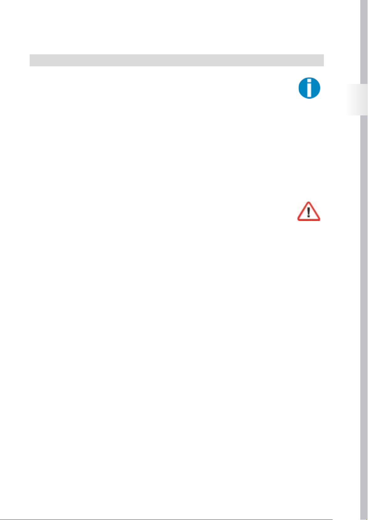
3. DELIVERY UNITS / DELIVERY CONTENTS
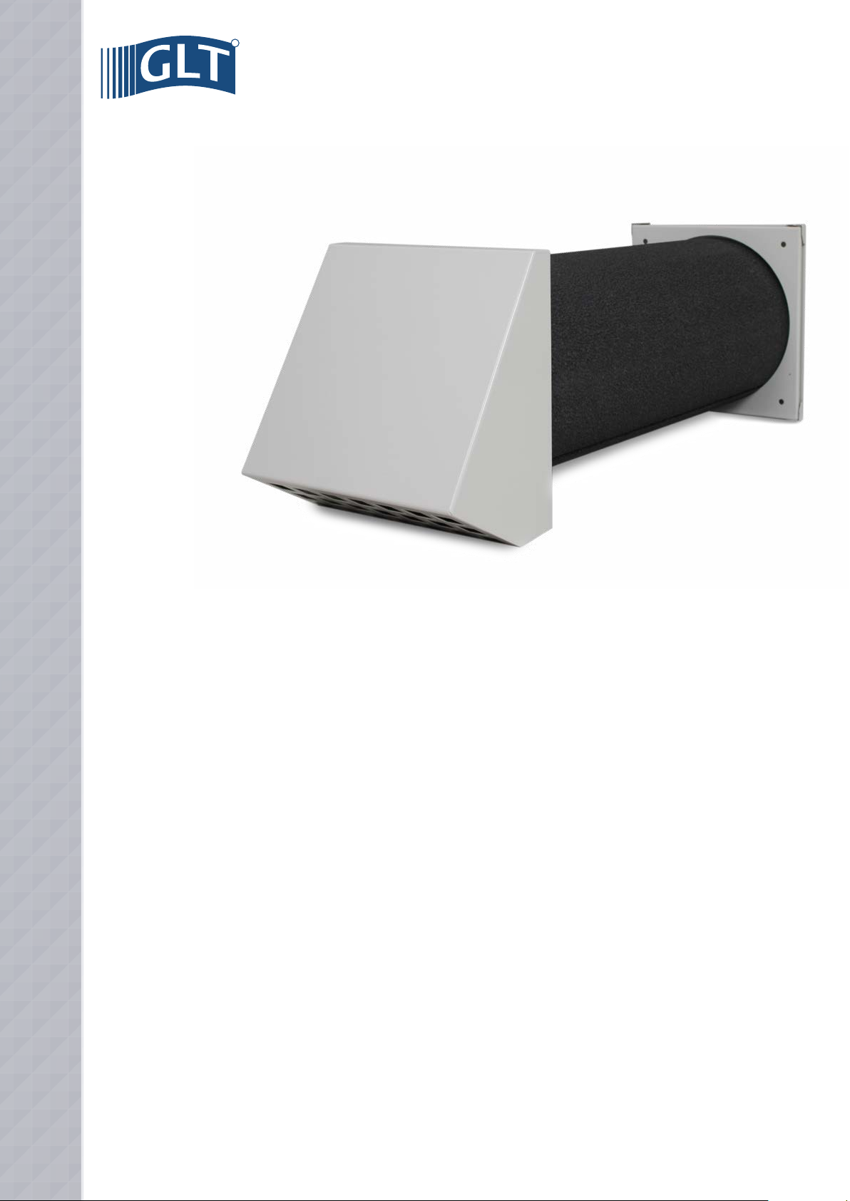
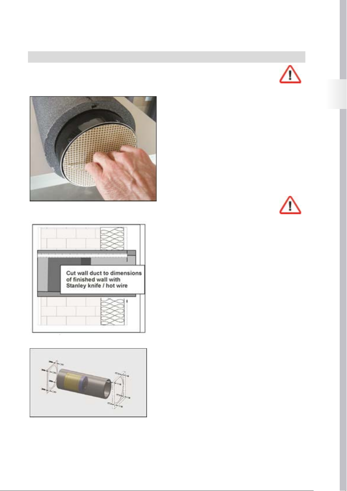
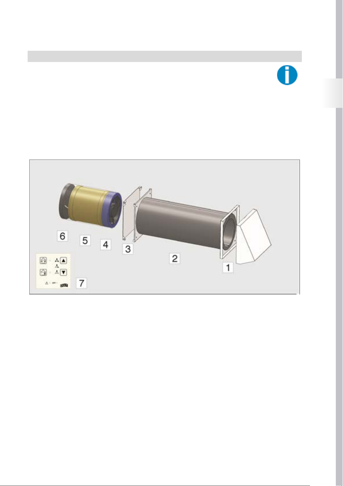
A complete Fox up ventilation unit consists of an EPS wall duct and a fan unit for insertion into the wall duct. The fan unit
consists of a reversible fan (12 V/DC) and a ceramic heat accumulator for heat recovery.
Air is fed into the room through a design plate with filter insert, and carried to the outside through a weatherproof protective
hood.
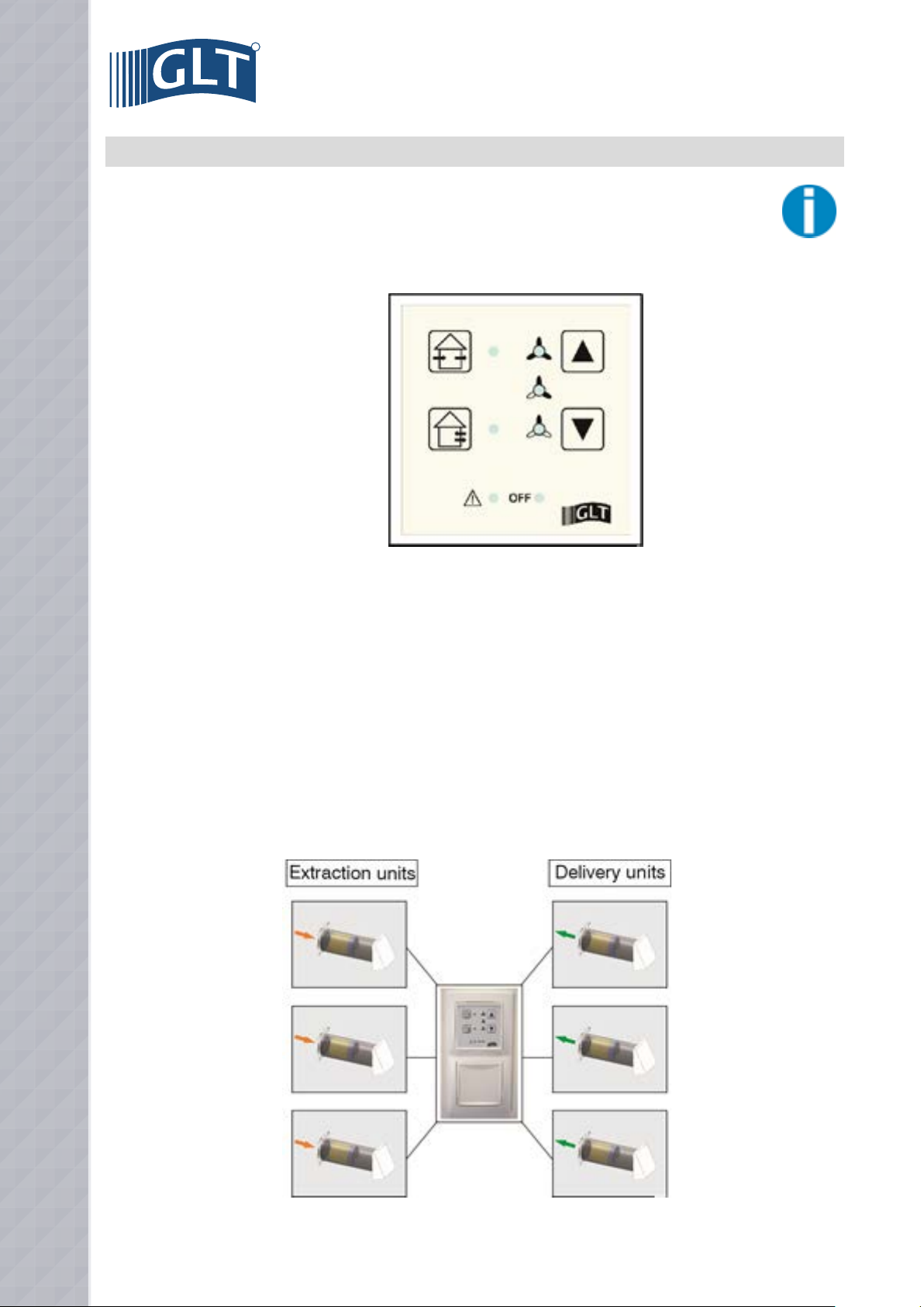
The unit is operated via an electronic control system with control panel, and up to six ventilation units (3 x delivery, 3 x
extraction) can be controlled by the electronic control system. The electronic system is installed in a double-cavity wall box for flush-mounted fitting.
The following delivery units are available for the various installation steps:
• Fox up-GP-Design, item no. 1145200: basic package consisting of wall duct (500 mm long), fan unit, inner plate, weatherproof protec-
tive hood and electronic control system with hollow-wall flush-mounted box.
• Fox up-EP-Design, item no. 1145201: supplementary package consisting of wall duct (500 mm long), fan unit, inner plate and weather-
proof protective hood.
• Fox up-Shell set 500 mm, item no. 1145210: shell set consisting of wall duct (500 mm long) and hollow-wall flush-mounted box.
• Fox up-Shell set 1000 mm, item no. 1145211: shell set consisting of wall duct (1000 mm long) and hollow-wall flush-mounted box.
• Fox up-Shell set 500 mm, item no. 1145212: shell set consisting of wall duct (500 mm long)
• Fox up-Shell set 1000 mm, item no. 1145213: shell set consisting of wall duct (1000 mm long)
• Fox up FMS-GP-Design, item no. 114220: final assembly basic package consisting of fan unit, inner plate, weatherproof protective
hood and electronic control system.
• Fox up FMS-EP-Design, item no. 1145221: final assembly supplementary package consisting of fan unit, inner plate, weatherproof
protective hood and electronic control system.
Fox up ventilation unit complete
1. Weatherproof protective hood (air inlet/outlet opening on outside)
2. EPS wall duct
3. Design valve (air inlet/outlet opening on room side)
4. Fan unit (incl. ceramic heat accumulator and filter insert)
5. Control panel / electronic control system
4
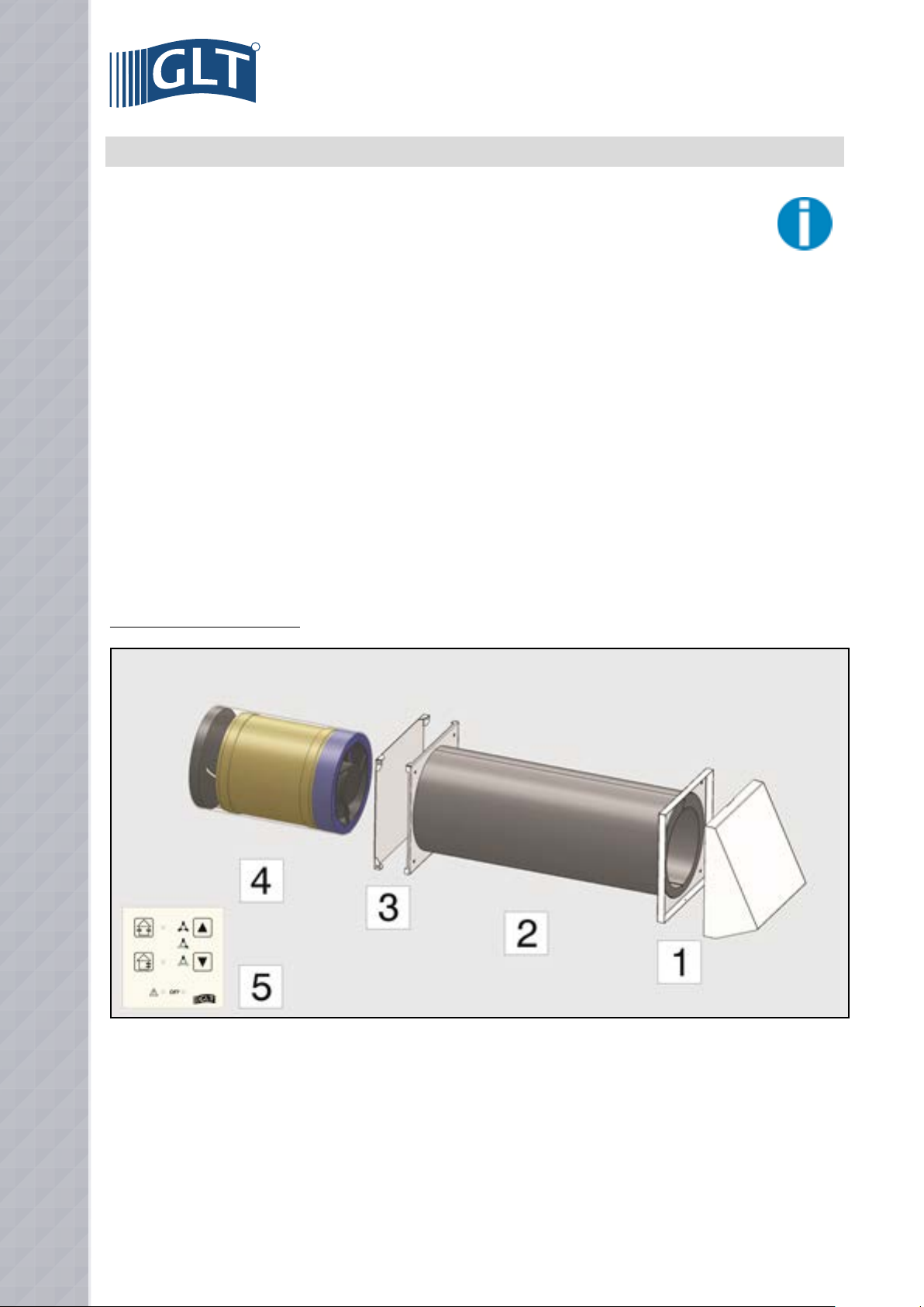
4. DIMENSIONS / TECHNICAL DATA
4.1 Dimensions Fox up ventilation unit - all dimensions in mm -
EN
Fox up inner plate
Fox up electronic control system Fox up inner plate
4.2 Technical Data
Fox up ventilation unit
Airflow: 15 / 30 / 40 m³/h
Efficiency of heat exchanger: <91 %
Supply voltage : 230 V/50 Hz
Power consumption : 1,4 / 2,6 / 3,7 W
Sound pressure level : 19 / 24 / 341 dB(A)
Filter class : G2
Permissible operating temperature: -20 tot +40 °C
IP protection class: 20
Weight: 5,5 kg
ø of wall duct (inner / outer): 153 / 198 mm
Length of wall duct: 500² / 1000³ mm
1. Sound pressure level, factory measurement
2. Fox up shell set 500 mm
3. Fox up shell set 1000 mm
5
R
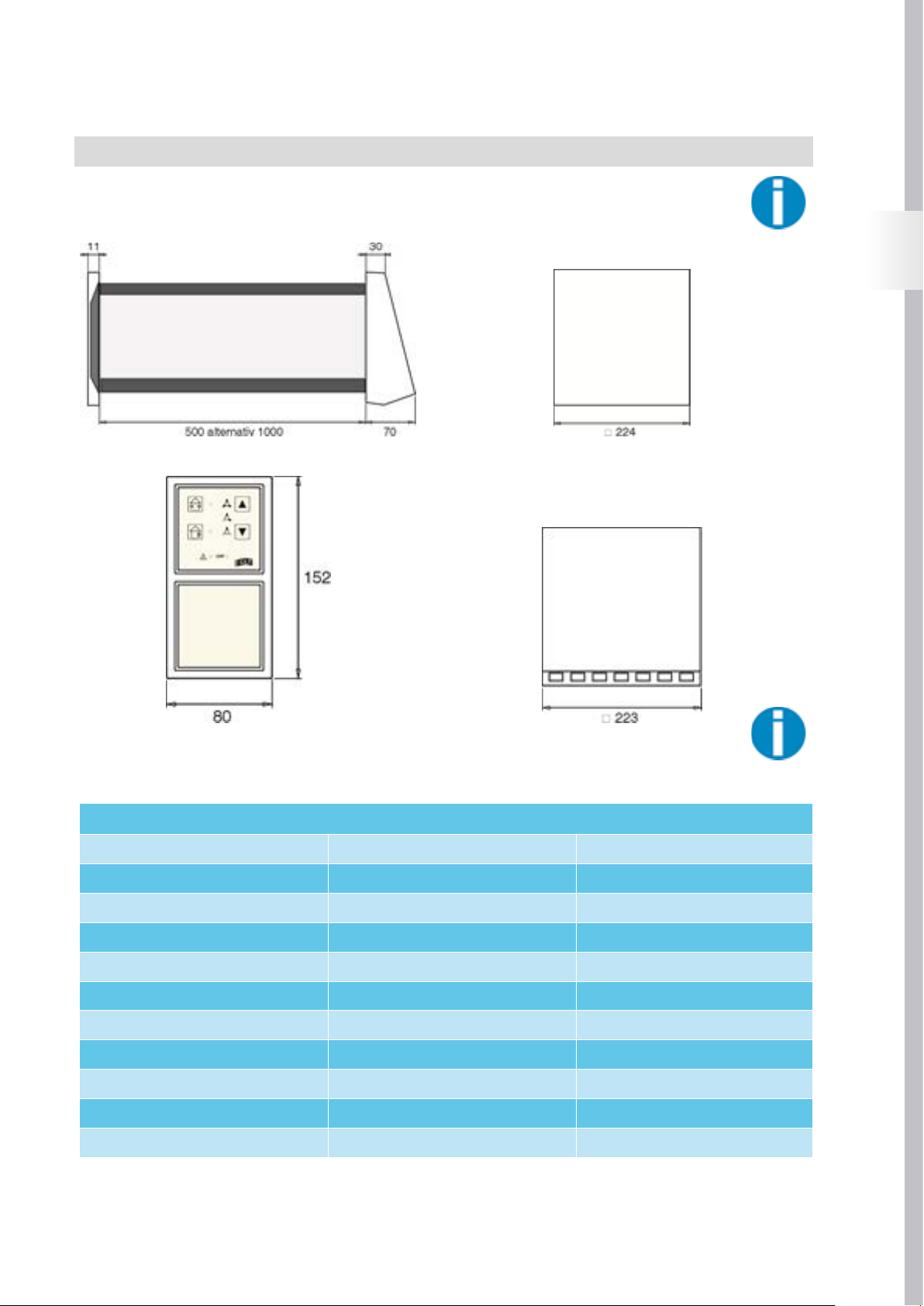
5. SELECTING INSTALLATION SITE
When selecting the installation position, pay
attention to the outer wall of the building, the units
needs to be positioned esthetical correct in the
building façade. For example: the units should be
installed at the same height as the windows and at equal distances
from windows.
The outside or room-side air inlet/outlet opening is recommended
at a minimum distance of 150 to 200 mm from adjacent façade
components and room corners!
Fox up ventilation units should be installed at a height of 1.6 to 1.8
m above the finished floor level, and the room-side air inlet/outlet
opening must not be covered by furniture or curtains.
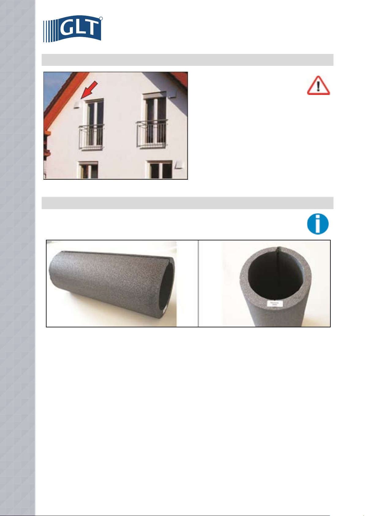
6. INSTALLATION OF WALL DUCT
EPS pipe wall duct
Inner ø 153, outer ø 198 mm, built-in gradient to outside (condensate drainage)
Wall ducts are available in two different lengths for Fox up ventilation units:
• Pipe length 500 mm: Fox up shell set 500 mm, item no. 1145210 or 1145212
• Pipe length 1000 mm: Fox up shell set 1000 mm, item no. 1145211 or 1145213
The delivery units Fox up-GP-Design and Fox up-EP-Design are supplied as standard with 500 mm wall ducts, the wall ducts are manu-
factured with a built-in gradient to the outside for condensate drainage (observe marking of outside, see fig. above).
6
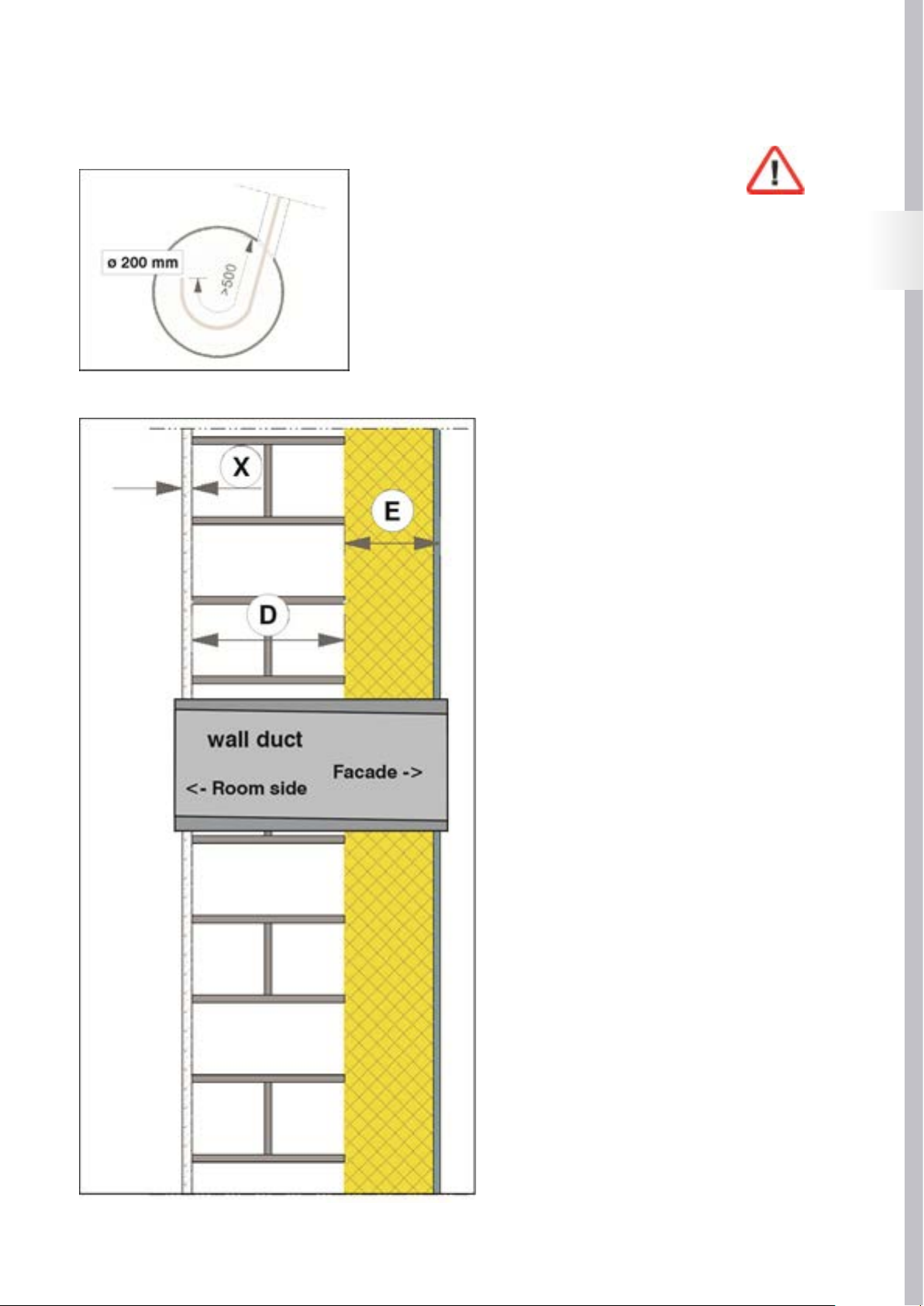
6.1 Tap hole drilling for wall duct
6.2 Installation of wall ducts
Create a hole with a diameter of 200 mm.
Feed the fan connecting lead (min. 3 x 0.25 mm2) into the wall duct.
The fan connecting lead must be perpendicular to the axe of the wall duct.
EN
Determine the overall thickness of the wall structure from
the dimensions of:
- The work measurement (D)
- The outside (E) (e.g. heat insulation + plaster)
- The inside (X) (e.g. plaster + tiles).
- The minimal length might never be shorter then 240 mm
Slide the wall duct into the wall opening, observing the
gradient to the outside / the room-side marking of the wall
duct. Allow the wall duct to stand perpendicular on the
both room and façade sides in accordance with the above
calculation.
Attention:
To ensure good movement of the fan / heat unit in the
wall duct, deformations of the wall duct due to external
pressure/tension should be avoided!
7
R
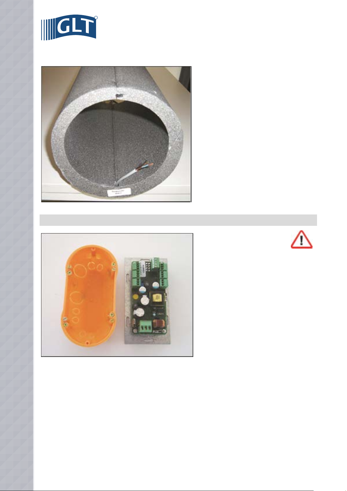
6.3 Wall duct for insertion of connecting lead of ventilation unit
Feed the electric connecting lead of the ventilation unit (see
view from
room side) into the wall duct.
Check the correct position of the wall duct (overhangs
outside / inside) and close the openings of the wall duct with
the protective covers.
Finally, fill the cavities (if any) between the wall opening and
the wall duct with non-pressurized
expanding foam.
7. INSTALLATION OF ELECTRONIC CONTROL SYSTEM
The electronic control system of Fox up ventilation units
is designed to be installed in a double hollow cavity
flush-mounted box. It can be used to control up to six Fox
up ventilation units.
The electronic control system is to be connected as stationary equipment with fixed wiring.
See page 9 for electrical connection diagram.
The supply voltage of the electronic control system is 230 V/50 Hz. A light-plastic sheathed cable 3 x 1.5 mm2 (e.g. NYM-J 3 x 1.5 mm2) is
recommended as an incoming line.
The ventilation units are supplied by 12 V DC in combination with a PWM controlling signal. Therefore, the ventilation units should not under
any circumstances be connected to the 230 V mains voltage of the electronic control system. A light-plastic sheathed cable 3 x 0.25 mm2
(e.g. LiYY 3 x 0.25 mm2) is recommended as a control line for the ventilation units with a maximum length of 10m.
8
8. ELECTRICAL CONNECTION OF ELECTRONIC CONTROL SYSTEM / VENTILATION UNIT
The electrical connection must be carried out according the local applicable standard. During installation
and maintenance work, all poles must be disconnected from the mains with a contact gap of at least 3 mm.
Disconnections must be immobilised in the open position!
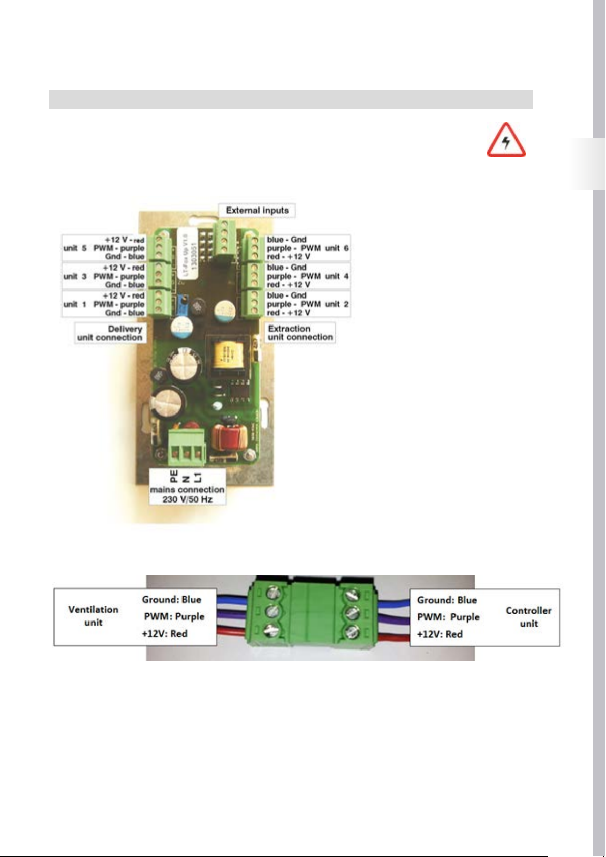
• Connecting the electronic control system:
Connecting a single unit:
A single ventilation unit is connected to the
Unit 1 or Unit 2 plug-in connector as shown in
the figure on the left.
When connected to the Unit 1 plug-in
connector, the unit can be used in “summer
mode” (see Ventilation mode page 16) as
a delivery unit. When connected to the Unit
2 plug-in connector, the unit can be used in
summer mode as an extraction unit.
Connecting several units:
Several units may be connected in pairs to
the plug-in connectors Unit 1 – Unit 2, Unit 3 –
Unit 4, Unit 5 – Unit 6; when used in pairs.
One of the units in the pair operates in delivery
mode, and the second unit operates in extraction mode, with the air direction of both units
swapping in the next interval.
EN
8.1 Connecting ventilation unit(s) – electronic control system
Fox up ventilation units are connected to the electronic control system via a plug-in connector supplied with the ventilation units as shown
above. Please observe polarity of delivery/extraction units (see fig. above)!
9
R
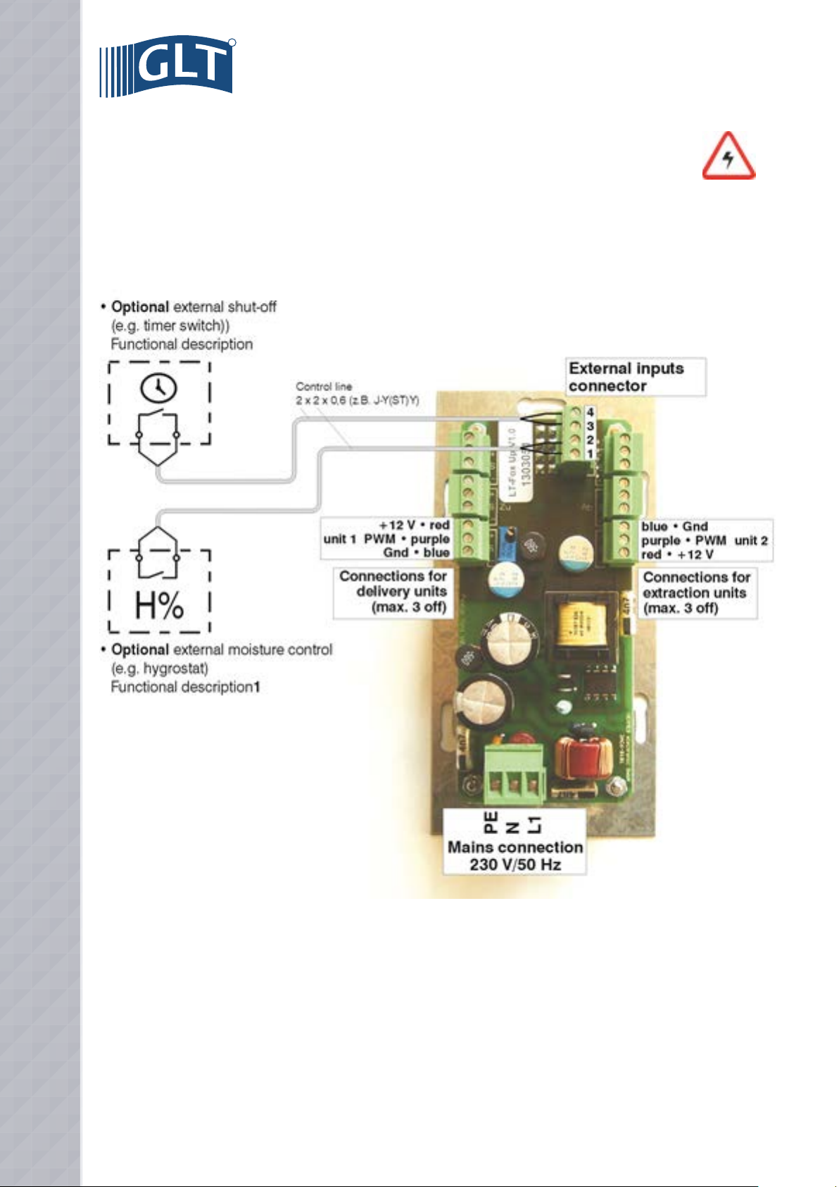
8.2 Electrical connection of external control elements
The operating mode of Fox up ventilation units is set to user-dependently via the control panel of the electronic control
system. Different operating variants can be selected with different power stages.
By connecting optional external control elements, a time- or moisture-dependent unit mode can also be activated. External control
elements are connected as shown above via the “external inputs” connector to the electronic control system of the ventilation units. The
function of the unit when controlled externally is described from page 19 of these instructions.
Connecting external control elements
A data line (e.g. 2 x 2 x 0.6 (e.g. J-Y(ST)Y) is recommended for connecting external control inputs (floating contacts).
10
9. INSTALLATION
9.1 Installation of fan unit
After the electrical connection has been made, the fan unit, consisting of the heat accumulator and fan, is inserted into the
wall duct:
Carefully slide the fan unit (fan towards façade) into the wall duct,
making sure that the fan’s connecting lead is not trapped / damaged.
The strap on the heat accumulator allows the fan unit to be aligned
during installation and removed from the wall duct for maintenance
purposes. Next, connect the plug-in connector between the connecting
leads of the ventilation unit and control unit.
9.2 Final assembly
EN
Once the insulation and plastering work has been completed, the wall duct
must be adapted to the dimensions of the finished wall by being cut with a
Stanley knife or hot wire flush with the wall on both room and façade sides.
Next install the support frame for the internal plate (room side) and the
weatherproof protective hood (façade side) of the ventilation unit using the
mounting materials which are supplied with the ventilation unit.
11
R
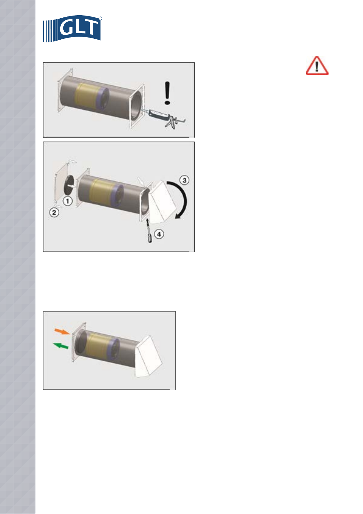
To prevent water from entering the wall opening,
the façade-side transition between the wall duct and the
support frame for the weatherproof protective hood must be
sealed all round with silicone or some other suitable sealant!
Slide the filter insert (1) supplied with the ventilation unit into
the wall duct and close the inner plate (2) of the ventilation
unit (magnetic catch).
Finally, install the unit’s façade-side weatherproof protective
hood (3). The hood is clipped onto a lug on the top of the
support frame and attached to the bottom of the support frame
using the fastening screw as supplied (4).
9.3 Functional test of ventilation unit(s)
Once installed, the function of the unit(s) must be checked. Before carrying out the check, make sure that the air passages of the ventilation unit(s) are free from assembly residues / foreign bodies and that all electrical work was carried out and completed in a technically
correct manner!
After switching on the power supply (generally via the electrical
installation’s automatic circuit-breakers), the ventilation unit can be
started using the electronic control system’s control panel. At start-up,
check all the unit functions as described at page 18 of the operating
instructions, making sure that the fan motor is running quietly and
smoothly.
Any malfunctions or faults found in the ventilation unit must be corrected before the unit is finally put into operation. Possible causes of faults
and their rectification are described in the section entitled Malfunctions
(see page 22).
Document the properly performed installation / functional testing of the ventilation unit(s) in the start-up report on page 13 of these
installation instructions.
12
10. START-UP REPORT
Building project:
Client:
Street:
Postcode / place:
Telephone:
E-Mail:
Ventilation unit(s) installed:
Type:
Number:
:
Fitter:
:
Installer:
Company:
Street:
Postcode / place:
Telephone:
E-Mail:
EN
• Installation work completed
• Electrical connection carried out / tested in a technically correct manner
• Unit function checked
• Filter insert(s) used
• Unit operator instructed (operation, maintenance)
• Unit documentation handed over (installation / operating instructions)
Option when operating units in conjunction with heat-producing appliances:
• Safety devices installed / tested
Place:
Date:
Fitter:
Client:
13
R
11. OPERATING INSTRUCTIONS
1. General notes ..........................................................................................................................................................................................................14
2. Unit description ...................................................................................................................................................................................................... 15
3. Settings for ventilation mode ...............................................................................................................................................................................16
4. Operating and display elements of electronic control system ........................................................................................................................ 18
5. External control inputs for electronic control system .......................................................................................................................................19
6 . Cleaning / Maintenance of the ventilation unit.................................................................................................................................................20
7. Error messages / Malfunctions ...........................................................................................................................................................................22
8. Maintenance report / Filter cleaning .................................................................................................................................................................. 24
1. GENERAL NOTES
Your Fox up ventilation unit allows you to create a healthy, pleasant indoor and ambient climate in your flat or house through
regulated, needs-based ventilation. Thanks to their easy installation and simple operation, the units are ideal for use in new
buildings and in case of refurbishment..
Fox up ventilation units are manufactured in accordance with the latest technological standards and acknowledged safety
regulations. General type approval has been applied for.
Please read these operating instructions carefully before using the unit, and follow the instructions during installation and during maintaining the unit. The operator of the ventilation unit is responsible for the condition and proper operation of the unit, with due regard for the
aforesaid instructions. Improper use, incorrectly carried out repair or maintenance work and structural changes may adversely affect the
function and safety of the unit and invalidate any warranty claims.
Installation and work on the ventilation unit should only be carried out by specially trained staff in accordance with the regulations on
occupational safety and accident prevention.
Fox up ventilation units with heat recovery are designed for the airing and ventilation of one or more rooms. The units should only be
used to deliver air. The delivery of aggressive, flammable or dust-laden media is not permitted. Never operate the unit without the filter
inserted.
The connection of ventilation pipes / connection to other ventilation systems is not permitted. Fox up ventilation units are not suitable for
construction drying, and should only be used once construction work has finished.
Operating the unit in conjunction with heat-producing appliances may require additional safety devices (Fire Regulations). Relevant
information is available from your local chimney sweep.
Prerequisites for optimal ventilation:
1. Where possible, keep doors and windows in the rooms being ventilated closed.
2. If several units are operated, overflow openings are to be provided between the rooms being ventilated (shortening of door
leaves, installation of door air grilles).
3. All ventilation units should be operated simultaneously in a ventilation setting as equal as possible.
14
2. UNIT DESCRIPTION
The Fox up ventilation unit is a decentralized ventilation system for controlled room ventilation with heat recovery. The use of
several units in pairs allows entire housing units / buildings to be ventilated.
The ventilation unit consists of an EPS wall duct that can be cut to length for wall thicknesses up to 500 m (alternatively
1000 mm) and a fan unit inserted into the wall duct. The fan unit consists of a reversible van (12 V/DC) and a ceramic heat accumulator for
heat recovery.
Air is fed into the room through a white, powder-coated design plate with a filter insert (filter class G2), and is carried to the outside
through a white, powder-coated weatherproof protective hood.
The unit is operated via the control panel of a wired electronic control system for flush-mounted fitting, and up to six ventilation units (3 x
delivery, 3 x extraction) can be controlled by the electronic control system.
Fox up ventilation unit complete
EN
1. Weatherproof protective hood (air inlet/outlet opening on outside)
2. EPS wall duct
3. Design valve (air inlet/outlet opening on room side)
4. Fan
5. Ceramic heat accumulator
6. Filter insert
7. Control panel / electronic control system
15
R
3. SETTINGS FOR VENTILATION MODE
3.1 Settings for ventilation mode
The operating variants of Fox up ventilation units are set using the control panel of the electronic control system of the ventilation units. Two basic functions with different fan powers can be set :
Summer mode function ------->
Winter mode function ------->
1. Summer mode function (delivery or extraction mode without heat recovery):
In this setting, the ventilation unit(s) work constantly in delivery* or extraction* mode, without heat recovery. *The operating mode
is defined by the electrical connection; the unit can be connected to the electronic control system as a delivery or extraction unit (see
Electrical connection page 9)
2. Winter mode function (delivery and extraction mode with heat recovery):
The ventilation unit(s) work alternately in 2 set time intervals. In the first interval (extraction phase), the “used” air in the room is sucked into the ventilation unit and pushed to the outside. During this process, the air flows through the ceramic heat accumulator inside
the ventilation unit, which extracts the heat from the air and stores it.
In the second interval (delivery phase), “fresh” outside air is sucked into the ventilation unit. It passes through the unit, and is heated by
the heat accumulator before entering the room.
If the Fox up ventilation units are used in pairs, the units in a pair work in opposite directions, i.e. the first unit in delivery mode and the
• Fox up ventilation system with 3 delivery and 3 extraction units:
16
3.2 Minimum ventilation option
To guarantee a permanent minimum ventilation, there is the option with Fox up ventilation units of setting a constant ventilation mode at a minimum power stage. Depending on the setting, the ventilation unit(s) work in summer or winter mode. It is
not possible to switch off the unit using the electronic control system’s control panel.
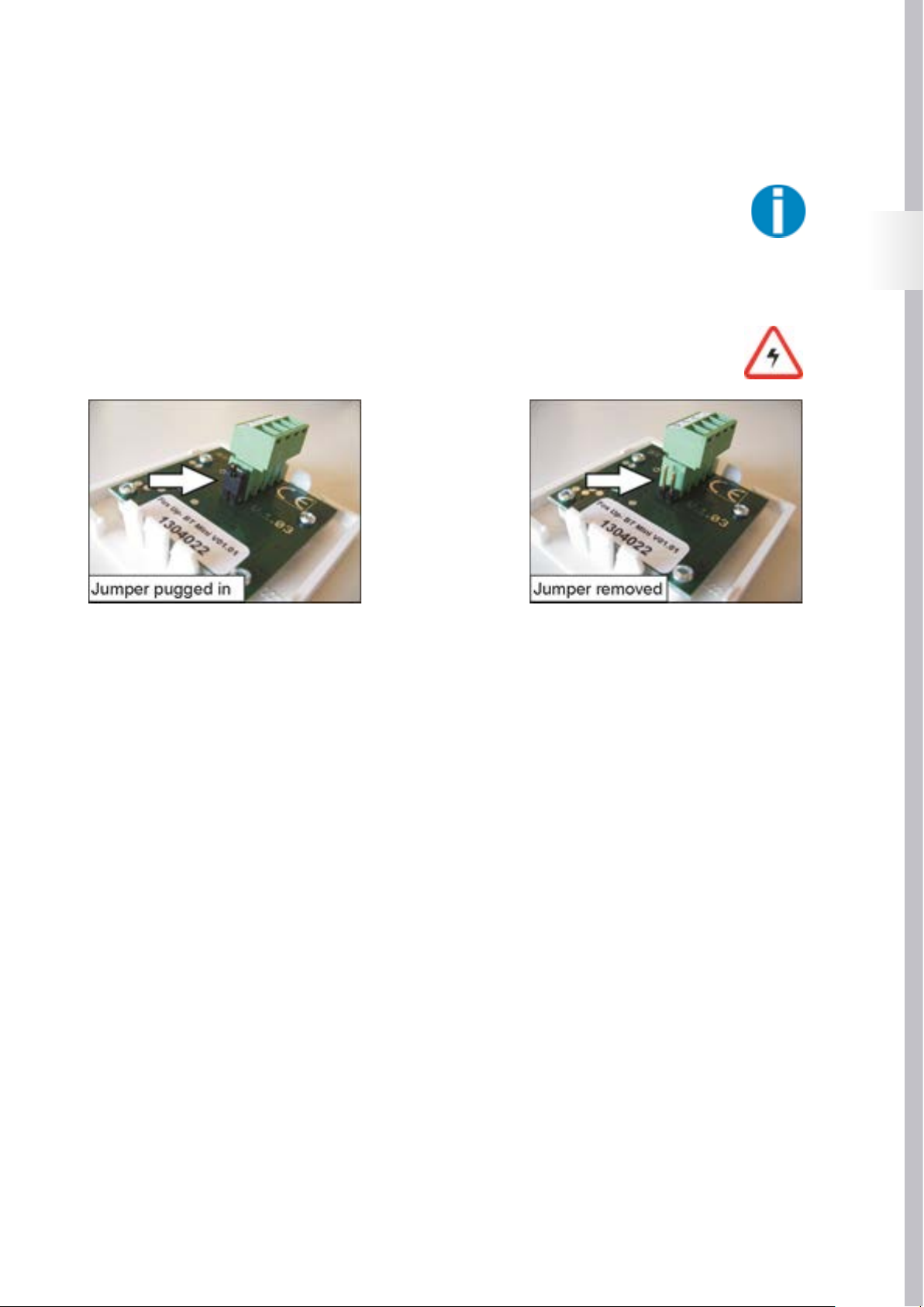
The minimum ventilation is activated / deactivated by re-plugging a jumper on the back of the control panel of the electronic control system. To activate the minimum ventilation, the control panel of the electronic control system must be detached (carefully remove control
panel), and the minimum ventilation is activated on the disconnected control panel as described below:
Attention:
Before changing the jumper position, all poles of the power supply to the ventilation unit must be disconnected. Disconnections must be immobilised in the open position!
If the jumper on the back of the control panel is
plugged in, the ventilation unit can be switched off
using the “down” arrow key (see fig. page 18).
Ventilation is interrupted, and the “unit off” signal
lamp (see fig. page 18) lights up.
< ---- alternative --->
If the jumper on the back of the control panel has
been removed or is only plugged into one pin, minimum ventilation is activated. The ventilation unit is
not completely switched off using the “down” arrow
key (see fig. page 18), but runs continuously at a
minimum power stage.
The activated minimum ventilation is signaled by
the pulsing “unit off” signal lamp (see fig. page
18).
EN
17
R
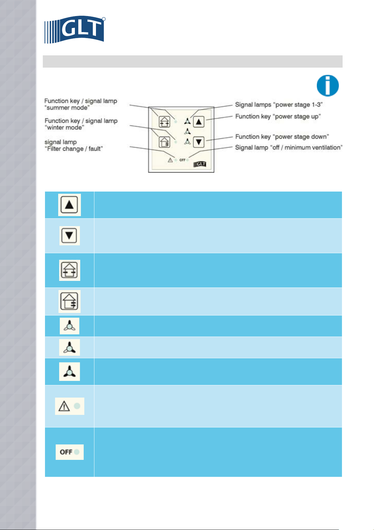
4. OPERATING AND DISPLAY ELEMENTS OF ELECTRONIC CONTROL SYSTEM
Pressing this key sets the unit to power stage 1. Pressing this key again selects the next power stage up.
Pressing this key switches the unit back to the next power stage down. If the unit is at power stage 1, pressing
this key again switches the unit off or returns it to minimum ventilation1.
1 minimum ventilation option, see page 17.
Pressing this key sets the unit to delivery or extraction mode2 without heat recovery (= summer mode). Summer
mode automatically switches back to winter mode, 8 hours after being activated. Pressing this key again
extends the summer mode by a further 8 hours.
2 depending on the electrical connection, see page 9.
Pressing this key sets the unit to alternate delivery/extraction mode with heat recovery (winter mode). During
the heating period, the device should be operated in this mode at all times.
If this symbol lights up, the unit is at power stage 1.
If this symbol lights up, the unit is at power stage 2.
AIf this symbol lights up, the unit is at power stage 3. Power stage 3 automatically switches back to power stage
2 one hour after being activated. If this symbol is flashing, the external moisture mode has been activated3.
3 External moisture mode option, see page 19.
If this indicator is permanently lit it indicates that the ventilation unit’s filter insert is due for inspection /
cleaning. The maintenance of the filter insert is described on page 20.
If this indicator is flashing it indicates a functional fault on the electronic control system’s control panel. The
electronic control system or the control panel must be checked by a qualified electrician, see error messages
page 22.
If this indicator lights up, the unit has been switched off via the “down” arrow key. Ventilation can be switched on
using the “up” arrow key.
If this indicator is pulsing, the unit has been switched to the “minimum ventilation” power stage via the “down”
arrow key (see page 17). The ventilation unit’s power stage can be increased using the “up” arrow key.
If this indicator is flashing, the unit has been switched off externally.
For External off option, see page 24.
18
5. EXTERNAL CONTROL INPUTS FOR ELECTRONIC CONTROL SYSTEM
• External input for moisture control
To quickly remove moisture when ventilating rooms with a high moisture load, e.g. baths, showers, the output of the Fox
up ventilation units can be increased depending on the moisture via an external hygrostat (= moisture-dependent switch).
The switching point (= moisture level) for increasing the power is set on the hygrostat. If the set moisture level (recommended settings,
summer: 65-80% RH, winter: 55-65% RH) is exceeded, the hygrostat activates power stage 3 in the ventilation unit.
Hygrostats are connected to contacts 1 and 2 of the “external inputs” connector on the electronic control system of the ventilation unit as
shown in the connection diagram on page 9.
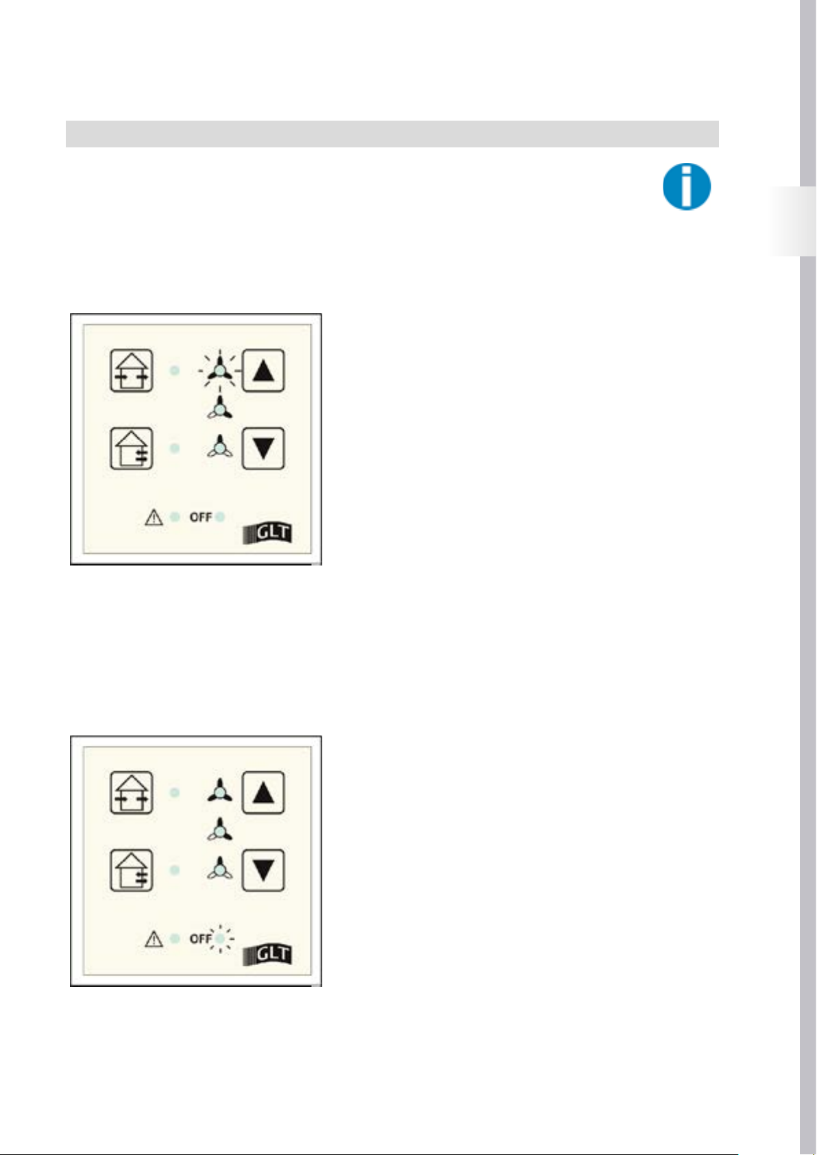
External moisture mode is displayed on the electronic control system’s control
panel by the flashing of the “power level 3” signal lamp.
If the power level is not changed manually on the control panel, the unit will
continue to operate at the last active power stage after the external contact is
switched off again.
Power stage 3 of the externally activated moisture mode can be reduced to power
stage 2 or 1 using the electronic control system’s control panel. To ensure that the
increased humidity is reduced, it is not possible to switch off the unit or return it to
the “minimum ventilation” power stage.
EN
• “Unit off” external input:
To prevent moisture damage in your rooms, Fox up ventilation units have been designed for continuous ventilation. If the ventilation nevertheless has to be interrupted* at certain times, the ventilation unit can be switched off via an external switch / time switch.
The switch / time switch is connected to contacts 3 and 4 of the “external inputs” connector on the electronic control system of the ventilation unit as shown in the connection diagram on page 9.
A ventilation unit switched off externally* is indicated on the control panel of the
electronic control system by the flashing of the “OFF” signal lamp.
If the power level is not changed manually on the control panel, the unit will
continue to operate at the last active power stage after the external contact is
switched on again.
A ventilation unit switched off externally* can be switched back on by pressing the
“power level up” key on the control panel of the electronic control system.
* The external switching off of the ventilation unit depends on the “minimum
ventilation” jumper setting (see page 17). If minimum ventilation is activated,
the operation of the system is not interrupted when switched off externally, but
reduced to minimum ventilation. Minimum ventilation is displayed on the remote
control by the pulsing of the “OFF” signal lamp.
19
R
6 . CLEANING / MAINTENANCE OF THE VENTILATION UNIT
The mechanical and electrical components of Fox up ventilation units are maintenance-free. Over time, however, airborne grease, particular matter, etc. cause the filter used in the unit to become dirty and leave a fine deposit on the fins of the heat accumulator and the blades
of the fan.
To guarantee the trouble-free operation of the ventilation unit, the filter insert, heat accumulator and fan must be checked and cleaned at
regular intervals as described below.
Dirt on the room- and/or façade-side air inlet/outlet openings (see ventilation unit components page 15) can be removed with a damp
cloth. Never use detergents containing solvents, as these corrode the surfaces (plastic coating) of the air inlet/outlet openings!
6.1 Maintenance of the filter insert
The filter used in the ventilation unit is monitored by an operating time meter in the electronic control system. After 3 months
(2,750 hours’ operation), the “filter change / fault” signal lamp lights up permanently on the control panel of the electronic
control system to indicate it is time to check the filter insert. Checking / cleaning of the filter insert is described below.
Attention:
Before all maintenance work, all poles of the power supply to the ventilation unit must be disconnected. Disconnections must be immobilized in the open position!
To check the filter, the inner valve (1) must be removed. The valve is attached to its support frame with magnets and can easily be pulled
out. After removing the inner valve, the filter insert (2) can be removed from the wall duct for checking.
• Remove filter insert
If only slightly soiled (no or little dust deposits), the filter insert can
be vacuumed or shaken. If there are significant dust deposits, the
filter insert must be rinsed with warm water (max. 60 °C).
In the case of significant grease deposits, the filter insert can be cleaned in water
mixed with detergent (degreaser). Any detergent residues must be completely
rinsed off with clean water.
Before putting the cleaned filter insert back into the ventilation unit, allow it to dry
completely. A damp filter will gather dust straight away!
Place the dried filter insert back into the wall duct of the ventilation unit and re-attach the ventilation unit’s inner valve to its support frame.
After checking / cleaning the filter insert and switching the power supply to the
ventilation unit back on, the operating time meter that monitors the filter insert must
be restarted. This is done via the control panel of the ventilation unit’s electronic
control system:
20
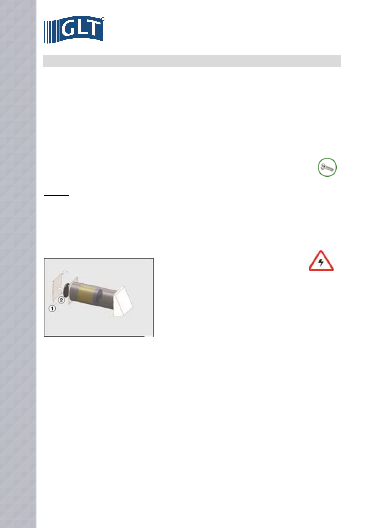
continued 6.1 Remove filter insert
The operating time meter is restarted by jointly pressing the “summer mode” and “winter
mode” keys and holding them down until the red “filter change / fault” LED goes out
(approx. 5 seconds).
Note:
Filter monitoring can also be restarted as described above without prior notice from the
filter change indicator, e.g. in connection with a regular overhaul.
The filter inspection request is issued on a time-dependent basis after 3 months’ operation,
regardless of how dirty the filter actually is. However, depending on the amount of dirt in
the fresh air that is delivered, it may be appropriate to change the filter sooner. It is therefore
recommended that the filter is checked in the first year after the ventilation unit is put into
operation at three-month intervals. The inspection/cleaning interval must be reduced if the
amount of dirt in the filter is clearly higher.
6.2 Maintenance of the heat accumulator / fan
The heat accumulator and fan should only be checked / cleaned by someone with specialist knowledge. It is therefore recommended that the ventilation unit be checked once a year by an expert. During this inspection, the “inner workings” of the unit
should be removed and checked for dirt / damage.
If damage is found, the affected parts are to be replaced before the ventilation unit is put back into use. Spare/replacement parts are
available from us at the address below.
Unit components should only be dismantled by a qualified electrician with the ventilation unit disconnected from the mains
(contact gap at least 3 mm).
EN
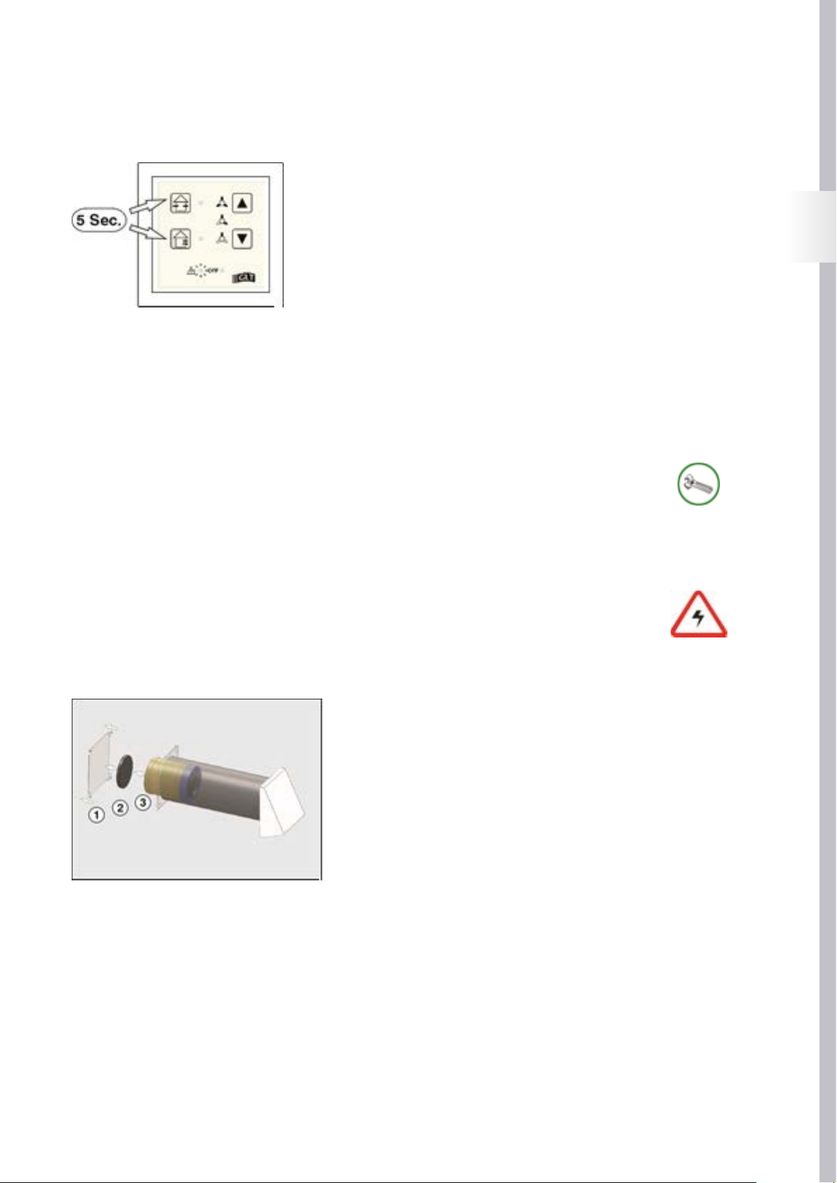
To check the heat accumulator and fan, the entire fan unit must be removed from the wall duct:
• Remove fan unit
To remove the fan unit, the ventilation unit’s inner plate (1) must be removed. The
plate is attached to its support frame with magnets and can easily be pulled of.
After removing the inner plate, the filter insert (2) and the fan unit (3) can be
removed from the wall duct.
If only slightly soiled, the heat accumulator / fan can be vacuumed. More significant
accumulations of dirt on the fan can be removed with a small brush or a paintbrush.
If the heat accumulator is heavily soiled, it must be removed from the fan unit and
rinsed with water.
21
R
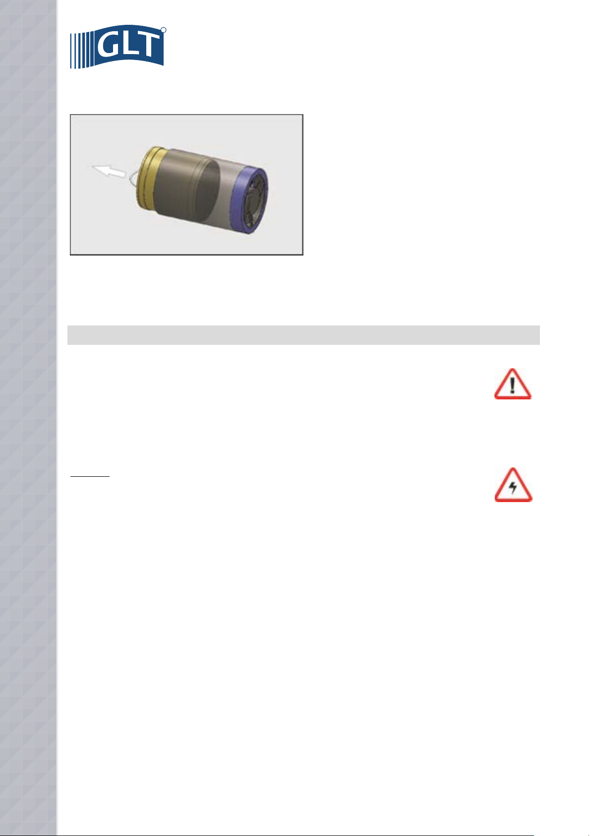
• Remove heat accumulator
The heat accumulator is inserted inside the fan unit and can be
removed from this for cleaning.
Dirt on the heat accumulator can be removed with a rose (shower /
bathtub) with warm water (max. 70 °C). For heavy soiling / grease
deposits, the heat accumulator can be cleaned in water mixed with
detergent (degreaser). Any detergent residues must be completely
rinsed off with clean water.
After being cleaned, the heat accumulator must be completely
dried (e.g. in the oven, max. 70 °C). A damp heat accumulator will
gather dust straight away!
Place the dried heat accumulator back in the fan unit and position the complete fan unit back in the wall duct.
To ensure the unit functions correctly, a complete functional test of the ventilation unit must be carried out after reinserting cleaned or
repaired components and switching the power back on (see page 19).
7. ERROR MESSAGES / MALFUNCTIONS
7.1 Error messages
Besides reporting that the filter needs checking, the “filter change / fault” signal lamp (see page 19) on the control panel
of the ventilation unit’s electronic control system also indicates a communication error between control unit and electronic
control system.
The communication error is reported by the repeated three-time flashing of the “filter change / fault” LED. If this message appears, the
connection between the ventilation unit’s control panel and the electronic control system must be checked by a qualified electrician.
Attention:
Before all maintenance work, all poles of the power supply to the ventilation unit must be disconnected.
Disconnections must be immobilized in the open position!
To check the connection between the control panel and the electronic control system, the control panel must be removed from the electronic control system. Then check the contacts of the connection for damage / foreign bodies / moisture.
Foreign bodies must be carefully removed from the connection. Mechanically damaged components or components damaged by moisture
must be replaced. Contact our spare/replacement parts department at the address below.
To ensure the unit functions correctly, a complete functional test of the ventilation unit must be carried out after repairing components
(see page 18).
22
7.2 Functional faults
The following table describes possible functional faults and how to solve the problem. Because faults are mainly caused
by errors in the power supply / electrical connection, the faults must be determined / rectified by a qualified electrician.
Therefore, if such faults occur, please contact the installer of your ventilation unit or us at the address below.
Fault Cause Rectification
- Check power supply (fuse)
Fan not working
- Power failure / interruption
- Connection error
- Fan blocked
- Fan faulty
- Control panel / electronic control system faulty
- Check all wire connections for correct connection,
connector for correct position (see page 9)
- Check fan. Remove blockage / foreign bodies
- Check and if necessary replace fan
- Check and if necessary replace control panel / electronic control system
EN
Noisy fan
Air flow too low
- Fan scraping due to dirt / foreign bodies
- Fan motor mounting faulty
- Filter insert dirty
- Heat exchanger dirty
- Wall duct / weatherproof protective hood dirty / locked
- Remove dirt / foreign bodies
- Replace fan
- Check / clean filter insert (see page 20)
- Check / clean heat exchanger (see page 21)
- Check wall duct / weatherproof protective hood, if
necessary remove dirt / foreign bodies
23
R
8. MAINTENANCE REPORT / FILTER CLEANING
Maintenance report
Maintenance work:
carried out by:
24
Filter cleaning
Filter element
Filter element
Filter element
Filter element
Filter element
Filter element
Filter element
Filter element
Filter element
Filter element
Filter element
Filter element
Filter element
Filter element
Filter element
checked cleaned
checked cleaned
checked cleaned
checked cleaned
checked cleaned
checked cleaned
checked cleaned
checked cleaned
checked cleaned
checked cleaned
checked cleaned
checked cleaned
checked cleaned
checked cleaned
checked cleaned
on:
on:
on:
on:
on:
on:
on:
on:
on:
on:
on:
on:
on:
on:
on:
EN
Filter element
Filter element
Filter element
Filter element
Filter element
Filter element
Filter element
Filter element
Filter element
Filter element
Filter element
Filter element
Filter element
Filter element
Filter element
checked cleaned
checked cleaned
checked cleaned
checked cleaned
checked cleaned
checked cleaned
checked cleaned
checked cleaned
checked cleaned
checked cleaned
checked cleaned
checked cleaned
checked cleaned
checked cleaned
checked cleaned
on:
on:
on:
on:
on:
on:
on:
on:
on:
on:
on:
on:
on:
on:
on:
Filter element
Filter element
Filter element
Filter element
checked cleaned
checked cleaned
checked cleaned
checked cleaned
on:
on:
on:
on:
25

R
26
MONTAGE- UND BEDIENUNGSANLEITUNG - DEUTSCH
INHALTSVERZEICHNIS MONTAGEANLEITUNG
1. Allgemeine Hinweise ............................................................................................................................................................................................ 28
2. Funktionsweise / Planungshinweise ..................................................................................................................................................................29
3. Liefereinheiten / Lieferumfang ............................................................................................................................................................................30
4. Abmessungen / Technische Daten .......................................................................................................................................................................31
5. Auswahl des Einbauortes......................................................................................................................................................................................32
6. Montage Wanddurchführung ..............................................................................................................................................................................32
7. Montage Steuerelektronik ................................................................................................................................................................................... 34
8. Elektrischer Anschluß .......................................................................................................................................................................................... 35
9. Montage Ventilatoreinheit / Funktionsprüfung .................................................................................................................................................37
10. Inbetriebnahmeprotokoll......................................................................................................................................................................................39
11. Bedienungsanleitung ...........................................................................................................................................................................................40
DE
Symbolik
Folgende Symbole werden in der vorliegenden Anleitung zur Kennzeichnung
besonderer Hinweise verwendet:
allgemeiner Hinweis / Information
Hinweis Gefahr durch
elektrische Spannung
Warnhinweis
Montage- / Wartungshinweis
27
R
1. ALLGEMEINE HINWEISE
Die Fox up Lüftungsgeräte sind nach aktuellem Stand der Technik und den anerkannten sicherheitstechnischen Regeln gebaut.
Montage- und Wartungsarbeiten am Lüftungsgerät dürfen nur durch ausgebildete Fachkräfte unter Einhaltung der Vorschriften zu Arbeitssicherheit und Unfallverhütung ausgeführt werden.
Der elektrische Anschluß muß nach VDE 0100 durchgeführt werden. Bei Installation und Wartungsarbeiten
muß eine allpolige Trennung vom Netz mit mindestens 3 mm Kontaktöffnungsweite vorgenommen werden, die
Netztrennung ist gegen Wiedereinschalten zu sichern !
Der Einsatz des Gerätes ist nur für den bestimmungsgemäßen Verwendungszweck zulässig, unsachgemäßer Gebrauch, mangelhaft
ausgeführte Installations- bzw. Wartungsarbeiten sowie bauliche Veränderungen können Funktion und Sicherheit des Lüftungsgerätes
beeinträchtigen und führen zum Erlöschen von Gewährleistungsansprüchen.
Lesen Sie vor Beginn von Montage- / Wartungsarbeiten diese Anleitung sorgfältig durch und beachten Sie die zu Montage und Wartung
angegebenen Hinweise.
Überprüfen Sie vor Installation des Gerätes die Lieferung hinsichtlich Vollständigkeit und Unversehrtheit und wenden Sie sich bei
fehlenden oder beschädigten Teilen direkt an unsere untenstehende Adresse.
Verwendungszweck
Fox up Lüftungsgeräte mit Wärmerückgewinnung sind zur kontrollierten Raumlüftung konzipiert. Die Geräte dürfen ausschließlich zur
Förderung von Luft eingesetzt werden, die Förderung von aggres-siven, entzündlichen oder stark staubhaltigen Medien ist nicht zulässig.
Betreiben Sie das Gerät nie ohne den im Gerät eingesetzten Filtereinsatz. Der Anschluß von Lüftungsleitungen anderer Lüftungs-systeme
ist nicht zulässig.
Fox up Lüftungsgeräte sind nicht zur Bautrocknung geeignet, der Betrieb der Geräte sollte erst nach Abschluß der Bautätigkeit erfolgen.
Der Gerätebetrieb in Verbindung mit Feuerstätten erfordert gegebenenfalls zusätzliche Sicher-heitseinrichtungen (Feuerungsverordnung
FeuV), entsprechende Informationen erhalten Sie beim regional zuständigen Schornsteinfeger.
Gerätestandort
Fox up Lüftungsgeräte dürfen nur im Gebäudeinneren montiert und betrieben werden, beachten Sie bei der Auswahl des Gerätestandortes,
daß das Lüftungsgerät für Revisions- und Wartungsarbeiten zugänglich ist. Die Gerätemontage in Nähe zu entzündlichen Flüssigkeiten
oder Gasen ist nicht zulässig. Zum Betrieb der Geräte ist ein Netzanschluß (230 V/50 Hz) erforderlich.
Montage
Beachten Sie bei Montage der Lüftungsgeräte die anerkannten Regeln der Technik (ARdT) bezüglich Geräteinstallation, Elektroarbeiten,
Brandschutz etc; sowie die Vorgaben zur Lüftung von Wohn-räumen (DIN 1946-6).
28

2. FUNKTIONSWEISE / PLANUNGSHINWEISE
2.1 Funktionsweise
Das Fox up Lüftungsgerät ist ein dezentrales Lüftungssystem zur kontrollierten Raumlüftung mit Wärmerückgewinnung. Der
paarweise Einsatz mehrerer Geräte ermöglicht die Lüftung kompletter Wohneinheiten / Gebäude.
Bei Betrieb mit Wärmerückgewinnung arbeitet das Lüftungsgerät in 2 einjustierten Zeitintervallen. Im ersten Intervall
(Abluftphase) wird durch Abluftbetrieb des Ventilators die “verbrauchte” Raumluft in das Lüftungsgerät gesaugt und nach außen abgeführt. Die Luft durchströmt dabei den Keramik-Wärme-speicher im Inneren des Lüftungsgerätes der die Wärme der Raumluft aufnimmt
und speichert.
Im zweiten Intervall (Zuluftphase) wird “frische” Außenluft über die Außenöffnung des Lüftungsgerätes angesaugt, sie durchströmt das
Gerät und wird vor Eintritt in den Raum durch den Wärmespeicher er-wärmt. Auf diese Weise können bis zu 90 % der in der Abluft enthaltenen Wärme an die dem Raum zugeführte Frischluft übergeben werden, das Prinzip des Be- und Entladens eines Wärmespeichers wird als
regenerative Wärmeübertragung bezeichnet.
Bei Betrieb eines Einzelgerätes entsteht im zu lüftenden Raum je nach Betriebsphase ein Überdruck (Zuluftphase) oder ein Unterdruck
(Abluftphase), um ein ausgeglichenes Verhältnis zwischen Zu- und Abluftmenge zu gewährleisten wird der paarweise Einsatz der Fox up
Geräte empfohlen. Die Steuerung der Lüftungsgeräte ermöglicht den gemeinsamen Betrieb von bis zu drei Gerätepaaren.
2.2 Planungshinweise
Vor der Montage von Fox up Lüftungsgeräten sollte ein Lüftungskonzept erstellt werden aus dem die Anzahl der Lüftungsgeräte, deren Einbauort, das Lüftungsprinzip (Querlüftung, Einzelraumlüftung) und die Position / Anzahl der zugehörigen
Steuerelektroniken zu entnehmen sind. Fox up Lüftungsgeräte ermöglichen folgende Lüftungsvarianten:
• Einzelraumlüftung mit einem Lüftungsgerät, im Intervall wechselnder Zu- / Abluftbetrieb mit Wärme rückgewinnung, alternativ Zu-* oder Abluftbetrieb* (* abhängig vom Elektroanschluß, sieheSeite 35).
DE
• Querlüftung mit paarweise betriebenen Lüftungsgeräten, im Intervall wechselnder Zu- / Abluftbetrieb
mit Wärmerückgewinnung (während ein Gerät eines Gerätepaares im Zuluftbetrieb läuft, arbeitet das
zugeordnete zweite Gerät im Abluftbetrieb, Luftrichtung beider Geräte im nächsten Intervall wechselnd),
alternativ Zu-* oder Abluftbetrieb* (* abhängig vom Elektroanschluß, siehe Seite 35).
Fox up Lüftungsgeräte sollten möglichst paarweise betrieben werden (siehe Funktionsweise), die Geräte-paare können sowohl in einem
Raum, als auch raumübergreifend eingesetzt werden, innerhalb einer Nutzungseinheit ist auch eine stockwerkübergreifende Zuordnung
möglich. Durch ausreichend dimen-sionierte Überströmöffnungen (z.B. Türluftgitter oder gekürztes Türblatt) muss eine Luftströmung
zwischen den zu lüftenden Räumen ermöglicht werden.
Damit durch eingeblasene Luft (Zuluftphase Lüftungsgerät) kein Geruchsübertrag in andere Räume erfolgt, sollten bei der Be-/ Entlüftung
von Küchen, Bädern oder Toiletten mit Fenstern immer zwei im Gegentakt arbeitende Geräte installiert werden. In innenliegenden,
fensterlosen Ablufträumen wie Küchen, Bädern und Toiletten dürfen die Fox up Geräte nicht eingesetzt werden da ein Anschluss der
Geräte an einen Schacht oder eine Rohrleitung nicht zulässig ist. Hier empfiehlt sich der Einsatz eines Abluftventilators gemäß DIN 18017
T.3, z.B. der Ventilatortyp BRAVO.
Die Geräteinstallation in Kellerräumen mit Lichtschächten ist ebenfalls nicht möglich, da eine Rezirkulation der Fortluft nicht ausgeschlossen werden kann. Um eine Rezirkulation bei Fassadenmontage der Geräte zu vermeiden, sollte zwischen einzelnen Geräten ein Mindestabstand von 1,2 m eingehalten werden.
Wir empfehlen, bei einer windexponierten Lage des Gebäudes (mittlere Windgeschwindigkeit > 5 m/s) auf den Einsatz des Gerätes zu
verzichten.
Um Zugerscheinungen durch den Betrieb der Lüftungsgeräte zu vermeiden, sollten die Geräte nicht im direkten Aufenthaltsbereich von
Personen (Sitzgelegenheiten, Betten) platziert werden, beachten Sie, daß der raumseitige Luftdurchlaß nicht durch Möbel oder Gardinen
beeinträchtigt wird.
29

R
3. LIEFEREINHEITEN / LIEFERUMFANG
Eine komplette Fox up Lüftungseinheit besteht aus einer EPS-Wanddurchführung und einer in die Wand-durchführung
eingeschobenen Ventilatoreinheit. Die Ventilatoreinheit besteht aus reversierbarem Venti-lator (12 V/DC) und Keramik-Wärmespeicher zur Wärmerückgewinnung.
Der raumseitige Luftdurchlaß erfolgt über eine Designblende mit Filtereinsatz, der Außenluftdurchlaß erfolgt über eine
Wetterschutzhaube.
Die Bedienung des Gerätes wird über eine Steuerelektronik mit Bedienfeld ausgeführt, über die Steuer- elektronik können bis zu sechs
Lüftungsgeräte (3 x Zuluft, 3 x Abluft) angesteuert werden. Die Montage der Elektronik erfolgt in einer Doppelhohlwanddose zur Unterputzmontage.
Für die unterschiedlichen Montageschritte sind folgende Liefereinheiten erhältlich:
• Fox up-GP-Design, Artnr. 18055: Grundpaket bestehend aus Wanddurchführung (500 mm lang),
Ventilatoreinheit, Innenblende, Wetterschutzhaube und Steuerelektronik mit Hohlwand-Unterputzdose.
• Fox up-EP-Design, Artnr. 18056: Ergänzungspaket bestehend aus Wanddurchführung (500 mm lang)
Ventilatoreinheit, Innenblende und Wetterschutzhaube.
• Fox up-Rohbausatz 500 mm, Artnr. 18018: Rohbausatz bestehend aus Wanddurchführung (500 mm lang)
und Hohlwand-Unterputzdose.
• Fox up-Rohbausatz 1000 mm, Artnr. 18022: Rohbausatz bestehend aus Wanddurchführung ( 1000 mm lang)
und Hohlwand-Unterputzdose.
• Fox up FMS-GP-Design, Artnr. 18059: Fertigmontage-Grundpaket bestehend aus Ventilatoreinheit,
Innenblende, Wetterschutzhaube und Steuerelektronik.
• Fox up FMS-EP-Design, Artnr. 18061: Fertigmontage-Ergänzungspaket bestehend aus Ventilatoreinheit,
Innenblende und Wetterschutzhaube.
• Fox up Lüftungseinheit komplett
1. Wetterschutzhaube (Luftdurchlaß Außenseite)
2. EPS-Wanddurchführung
3. Designblende (Luftdurchlaß Raumseite)
4. Ventilatoreinheit (inkl. Keramik-Wärmespeicher und Filtereinsatz)
5. Bedienteil / Steuerelektronik
30

4. ABMESSUNGEN / TECHNISCHE DATEN
4.1 Fox up Lüftungseinheit - alle Maßangaben in mm -
DE
Fox up Innenblende
Fox up Steuerelektronik Fox up Wetterschutzhaube
4.2 Technische Daten
Fox upLüftungseinheit
Luftleistung : 15 / 30 / 40 m³/h
Wirkungsgrad Wärmetauscher : <91 %
Versorgungsspannung : 230 V/50 Hz
Leistungsaufnahme : 1,4 / 2,6 / 3,7 W
Schalldruckpegel : 19 / 24 / 341 dB(A)
Filterklasse : G2
zulässige Betriebstemperatur : -20 tot +40 °C
IP-Schutzart : 20
Gewicht : 5,5 kg
ø Wanddurchführung (innen / außen) : 153 / 198 mm
Länge Wanddurchführung : 500² / 1000³ mm
1 Schalldruckpegel, werkseitige Messung
2 Fox up Rohbausatz 500 mm
3 Fox up Rohbausatz 1000 mm
31

R
5. AUSWAHL DES EINBAUORTES
Achten Sie bei der Auswahl des Einbauortes auf die
Außen-ansicht des Gebäudes, damit sich die Geräte
harmonisch in die Gebäudefassade einfügen, sollten
die Geräte beispiels-weise in gleicher Höhe / mit
gleichem Abstand zu Fenstern montiert werden.
Beachten Sie die Abmessungen der außen- bzw. raum-seitigen
Luftdurchlässe, es wird empfohlen um die Wand-durchführung
einen Mindestabstand von 150 bis 200 mm zu angrenzenden
Fassadenbauteilen / -elementen und Raumecken einzuhalten !
Der Einbau der Fox up Lüftungsgeräte sollte in 1,6 bis 1,8 m Höhe
über dem Fertigfußboden erfolgen, der raumseitige Luftdurchlaß
der Geräte darf nicht durch Möbel oder Gardinen abgedeckt
werden.
6. MONTAGE WANDDURCHFÜHRUNG
Wanddurchführung EPS-Rohr
ø innen 153, ø außen 198 mm, integriertes Gefälle nach außen (Kondensatableitung)
Für die Fox up Lüftungsgeräte sind Wanddurchführungen in zwei unterschiedlichen Längen erhältlich:
• Rohrlänge 500 mm : Fox up Rohbausatz 500 mm, Artnr. 18018
• Rohrlänge 1000 mm : Fox up Rohbausatz 1000 mm, Artnr. 18022
Die Liefereinheiten Fox up-GP-Design und Fox up-EP-Design werden standardmäßig mit 500 mm langen Wanddurchführungen gelie-
fert, alle Wanddurchführungen sind zur Ableitung von Kondensat mit inte-griertem Gefälle nach außen gefertigt (Markierung Raumseite
beachten, siehe Abb. oben.)
32

6.1 Kernlochbohrung Wanddurchführung
6.2 Montage Wanddurchführung
Erstellen Sie eine Kernlochbohrung im Durchmes-ser 200 mm.
Führen Sie die Ventilator-Anschlußleitung (mind.
3 x 0,25 mm²) in den Wanddurchbruch ein. Lassen Sie die Ventilator-Anschlußleitung in Länge der Wanddurchführung überstehen.
DE
Bestimmen Sie das Gesamtmaß des Wandaufbaus aus den Maßen
Wandstärke Rohbaumaß D und den Maßen für den Wandabschluss
außen E (z.B. Wärmedämmung + Putz) und innen X (z.B. Putz + Fliesen).
Schieben Sie die Wanddurchführung in den Wand-durchbruch ein,
beachten Sie das Gefälle nach außen / die raumseitige Markierung
der Wand-durchführung. Lassen Sie die Wanddurchführung entsprechend
Ihrer vorstehenden Berechnung raum- und fassadenseitig überstehen.
Achtung:
Um eine spannungsfreie Montage / Demontage (Wartung) des Ventilators
/ des Wärmespeichers in der Wanddurchführung sicherzustellen, sind
Ver-formungen der Wanddurchführung durch äußeren Druck / Verspannung zu vermeiden !
33

R
6.3 Wanddurchführung Einführung Anschlußleitung Lüftungseinheit
Führen Sie die Elektro-Anschlußleitung der Lüftungseinheit
seitlich (Ansicht Raumseite) in die Wanddurchführung ein.
Überprüfen Sie die korrekte Position der Wanddurchführung
(Überstände außen / innen), und verschließen Sie die
Öff-nungen der Wanddurchführung mit den mitgelieferten
Putz-schutzdeckeln.
Verfüllen Sie abschließend mögliche Hohlräume zwischen
Wanddurchbruch und Wanddurchführung mit nicht-drückendem Montageschaum.
7. MONTAGE STEUERELEKTRONIK
Die Steuerelektronik der Fox up Lüftungsgeräte ist zur
Montage in eine Doppel-Hohlwand Unterputzdose konzipiert, sie kann zur Ansteu-erung von bis zu sechs Fox up
Lüftungsgeräten eingesetzt werden.
Die Steuerelektronik ist als ortsfestes Betriebs-mittel mit
fest verlegten Leitungen anzu-schließen.
Elektrischer Anschluß siehe Seite 35.
Die Versorgungsspannung der Steuerelektronik beträgt 230 V/50 Hz, als Zuleitung wird eine Mantel-leitung 3 x 1,5 mm² (z.B. NYM-J 3x1,5
mm²) empfohlen.
Die Steuerung der Lüftungsgeräte erfolgt durch 12 V Gleichspannung (DC), die Lüftungsgeräte dürfen daher keinesfalls mit der 230 V
Netzspannung der Steuerelektronik verbunden werden. Als Steuerleitung für die Lüftungsgeräte wird eine Mantelleitung 3 x 0,25 mm²
(z.B. LiYY 3 x 0,25 mm²) empfohlen, die Länge der einzelnen Steuerleitungen sollte max. 15 m betragen.
34

8. ELEKTRISCHER ANSCHLUSS
Der elektrische Anschluß muß nach VDE 0100 durchgeführt werden. Bei Installation und Wartungsarbeiten
muß eine allpolige Trennung vom Netz mit mindestens 3 mm Kontakt-öffnungsweite vorgenommen werden, die
Netztrennung ist gegen Wiedereinschalten zu sichern !
• Anschluß Steuerelektronik
+12 V - rot
Gerät 5 PWM - lila
Gnd - blau
+12 V - rot
Gerät 3 PWM - lila
Gnd - blau
+12 V - rot
Gerät 1 PWM - lila
Gnd - blau
Anschluß
Zuluftgeräte
externe Eingänge
siehe Seite 11
blau - Gnd
lila - PWM Gerät 6
rot - +12 V
blau - Gnd
lila - PWM Gerät 4
rot - +12 V
blau - Gnd
lila - PWM Gerät 2
rot - +12 V
Anschluß
Abluftgeräte
DE
• Anschluß Einzelgerät:
Der Anschluß eines einzelnen Lüft-ungsgerätes erfolgt am
Steck-verbinder Gerät 1 oder
Gerät 2 wie in nebenstehender
Abbildung dar-gestellt.
Bei Anschluß am Steckverbinder Gerät 1
kann das Gerät in Funktion „Sommerbetrieb“
(siehe Lüftungs-betrieb Seite 42) als
Zuluftgerät eingesetzt werden, bei Anschluß
am Steckverbinder Gerät 2 kann das Gerät im
Sommerbetrieb als Abluft-gerät eingesetzt
werden.
• Anschluß mehrerer Geräte:
Der Anschluß mehrerer Geräte er-folgt in
paarweiser Zuordnung an den Steckverbindern
Gerät 1 - Gerät 2, Gerät 3 - Gerät 4, Gerät 5
- Gerät 6; im paarweisen Betrieb arbeitet ein
Gerät eines Geräte-paares im Zuluftbetrieb,
das zuge-ordnete zweite Gerät im Abluft-betrieb, die Luftrichtungen beider Geräte werden
im Intervall gewech-selt.
N
L1
PE
Netzanschluß
230 V/50 Hz
8.1 Anschluß Lüftungsgerät(e) - Steuerelektronik
Lüftungsgerät
Gnd • blau
PWM • lila
+12 V • rot
blau • Gnd
lila • PWM
rot • +12 V
Steuerelektronik
Der Anschluß der Fox up Lüftungsgeräte an der Anschlußleitung der Steuerelektronik erfolgt über eine im Lieferumfang der Lüftungsgeräte enthaltene Steckverbindung wie vorstehend dargestellt. Bitte Polung Zu- / Abluftgeräte beachten (siehe Abb. oben)!
35

R
8.2 Elektrischer Anschluß externe Steuerelemente
Die Einstellung der Betriebsweise der Fox up Lüftungsgeräte erfolgt nutzerabhängig über das Bedienfeld der Steuerelektronik, es können unterschiedliche Betriebsvarianten mit verschiedenen Leistungsstufen angewählt werden.
Durch Anschluß optionaler, externer Steuerelemente kann zusätzlich ein zeit- oder feuchteabhängiger Gerätebetrieb aktiviert werden,
der Anschluß der externen Steuerelemente erfolgt wie nachstehend dargestellt über den Anschlußstecker “externe Eingänge” an der
Steuerelektronik der Lüftungsgeräte.
Die Gerätefunktion bei externer Ansteuerung ist ab Seite 45 dieser Anleitung beschrieben.
• Anschluß externe Steuerelemente
• Option externe Abschaltung
(z.B. Zeitschaltuhr)
Funktionsbeschreibung siehe Seite 22
Anschlußstecker
Steuerleitung
externe Eingänge
2 x 2 x 0,6 (z.B. J-Y(ST)Y)
• Option externe Feuchtesteuerung
(z.B. Hygrostat)
Funktionsbeschreibung siehe Seite 21
Gerät 1 PWM • lila
+12 V • rot
Gnd • blau
Anschlüsse Zuluftgeräte
(max. 3 Stck.)
blau • Gnd
lila • PWM Gerät 2
rot • +12 V
Anschlüsse Abluftgeräte
(max. 3 Stck.)
Netzanschluß
230 V/50 Hz
Zum Anschluß der externen Steuereingänge (potentialfreie Kontakte) wird eine Datenleitung (z.B. 2 x 2 x 0,6 (z.B. J-Y(ST)Y) empfohlen.
36

9. MONTAGE VENTILATOREINHEIT / FUNKTIONSPRÜFUNG
9.1 Montage Ventilatoreinheit
Nach Ausführung des Elektroanschlusses wird die aus Wärmespeicher und Ventilator bestehende Venti-latoreinheit in die
Wanddurchführung eingeschoben:
Schieben Sie die Ventilatoreinheit (Ventilator in Richtung Fassade)
vorsichtig in die Wanddurchführung ein und achten Sie darauf, daß die
Anschlußleitung des Ventilators dabei nicht geknickt / be-schädigt
wird.
Mit der am Wärmespeicher angebrachten Halteschlaufe kann die Ventilatoreinheit bei der Montage ausgerichtet und zu Wartungs-zwecken
wieder aus der Wanddurchführung ausgezogen werden.
Verbinden Sie anschließend die Steckverbindung Anschlußleit-ung
Lüftungsgerät - Anschlußleitung Steuergerät.
9.2 Fertigmontage
DE
Wanddurchführung mit
Teppichmesser / Heißdraht
auf Maß Fertigwand kürzen
Nach Abschluß der Dämm- / Putzarbeiten muß die Wanddurchführung dem
Maß der Fertigwand angepaßt werden indem sie mit einem Teppichmesser
oder einem Heißdraht raum- und fassadenseitig wandbündig ge-kürzt wird.
Montieren Sie anschließend die Halterahmen der Innen-blende (Raumseite)
und der Wetterschutzhaube (Fass-adenseite) des Lüftungsgerätes mit dem
im Lieferum-fang des Lüftungsgerätes enthaltenen Montagematerial oder
mit für den speziellen Anwendungsfall geeigneten Befestigungselementen.
37

R
Zum Schutz vor Wassereintritt in den Wanddurchbruch muß der fassadenseitige Übergang zwischen
Wand-durchführung und Halterahmen Wetterschutzhaube
umlaufend mit Silikon oder entsprechend geeignetem
Dichtmaterial abgedichtet werden !
Setzen Sie den im Lieferumfang des Lüftungsgerätes
enthaltenen Filtereinsatz ( 1 ) in der Wanddurchführung ein
und verschließen Sie die Innenblende ( 2 ) des Lüft-ungsgerätes (Magnetverschluß).
Montieren Sie abschließend die fassadenseitige Wetter-schutzhaube ( 3 ) des Gerätes, die Haube wird mit einer angebrachten Lasche an der Oberkante des Halte-rahmens eingehängt
und mit der mitgelieferten Befestig-ungsschraube ( 4 ) an der
Unterkante des Halterahmens fixiert.
9.3 Funktionsprüfung Lüftungsgerät(e)
Nach Abschluß der Montagetätigkeit muß die Gerätefunktion überprüft werden, vor der Überprüfung ist sicherzustellen, daß die Luftwege
des Lüftungsgerätes / der Lüftungsgeräte frei von Montagerückständen / Fremdkörpern sind und sämtliche Elektroarbeiten fachgerecht
ausgeführt und abgeschlossen wurden !
Nach dem Einschalten der Stromversorgung (in der Regel über den
Sicherungsautomaten der Elektro-installation) kann das Lüftungsgerät
über das Bedienfeld der Steuerelektronik in Betrieb genommen werden,
überprüfen Sie bei der Inbetriebnahme alle in der Bedienungsanleitung
ab Seite 44 beschriebenen Gerätefunktionen, achten Sie während
der Überprüfung auf ruhigen, gleichmäßigen Lauf des Ventilatormotors.
Festgestellte Fehlfunktionen bzw. Störungen am Lüft-ungsgerät müssen
vor der endgültigen Inbetriebnahme des Gerätes behoben werden,
mögliche Fehlerursachen und deren Behebung sind im Kapitel Funktions-störungen (siehe Seite 48) beschrieben.
Dokumentieren Sie die ordnungsgemäß ausgeführte Installation / Funktionsprüfung der / des Lüftungs-geräte(s) im Inbetriebnahmeprotokoll auf Seite 39 dieser Montageanleitung.
38

10. INBETRIEBNAHMEPROTOKOLL
Bauvorhaben:
Bauherr :
Straße :
PLZ / Ort :
Telefon :
e-mail :
Eingebaute(s) Lüftungsgerät(e):
Typ :
Anzahl :
Monteur :
Installateur:
Firma :
Straße :
PLZ / Ort ::
Telefon :
e-mail :
DE
• Montagearbeiten komplett abgeschlossen
• Elektroanschluß ordnungsgemäß ausgeführt / geprüft
• Gerätefunktion überprüft
• Filtereinsatz / -einsätze eingesetzt
• Einweisung Gerätebetreiber durchgeführt (Bedienung, Wartung)
• Geräteunterlagen übergeben (Montage- / Bedienungsanleitung)
Option bei Gerätebetrieb in Verbindung mit Feuerstätten:
• Sicherheitseinrichtungen montiert / geprüft
Ort :
Datum :
Monteur :
Bauherr :
39

R
11. BEDIENUNGSANLEITUNG
Inhaltsverzeichnis Bedienungsanleitung
1. Allgemeine Hinweise ............................................................................................................................................................................................40
2. Gerätebeschreibung .............................................................................................................................................................................................. 41
3. Einstellungen Lüftungsbetrieb ............................................................................................................................................................................ 42
4. Bedien- und Anzeigeelemente..............................................................................................................................................................................44
5. Externe Steuereingänge .......................................................................................................................................................................................45
6. Reinigung / Wartung ............................................................................................................................................................................................ 46
7. Fehlermeldungen / Funktionsstörungen ............................................................................................................................................................ 48
8. Wartungsprotokoll / Filterreinigung ...................................................................................................................................................................50
1. ALLGEMEINE HINWEISE
Mit Ihrem Fox up Lüftungsgerät sind Sie durch eine geregelte, bedarfsgerechte Lüftung in der Lage in Ihrer Wohnung oder
Ihrem Haus ein gesundes, angenehmes Raum- und Wohlfühlklima zu schaffen. Die Geräte sind durch ihre unkomplizierte
Montage und einfache Bedienung optimal für den Einsatz in Neubau und Sanierung geeignet.
Fox up Lüftungsgeräte werden nach aktuellem Stand der Technik und den anerkannten sicherheits-technischen Regeln
gefertigt. Eine allgemeine bauaufsichtliche Zulassung ist beantragt.
Lesen Sie bitte diese Bedienungsanleitung vor der Nutzung des Gerätes sorgfältig durch und beachten Sie die Hinweise zu Inbetriebnahme
und Wartung des Gerätes. Der Betreiber des Lüftungsgerätes ist unter Beachtung der angegebenen Hinweise für den einwandfreien Zustand und den bestimmungsgemäßen Betrieb des Gerätes verantwortlich. Unsachgemäßer Gebrauch, mangelhaft ausgeführte Instandsetzungs- bzw. Wartungsarbeiten sowie bauliche Veränderungen können Funktion und Sicherheit des Gerätes beeinträchtigen und führen zum
Erlöschen von Gewährleistungsansprüchen.
Montage und Arbeiten am Lüftungsgerät dürfen nur durch ausgebildete Fachkräfte unter Einhaltung der Vorschriften zu Arbeitssicherheit
und Unfallverhütung ausgeführt werden.
Fox up Lüftungsgeräte mit Wärmerückgewinnung sind zur Be- und Entlüftung von einem oder mehreren Räumen konzipiert. Die Geräte
dürfen ausschließlich zur Förderung von Luft eingesetzt werden, die Förderung von aggressiven, entzündlichen oder stark staubhaltigen
Medien ist nicht zulässig. Betreiben Sie die Geräte nie ohne den eingesetzten Filtereinsatz.
Der Anschluß von Lüftungsleitungen / der Anschluß an andere Lüftungssysteme ist nicht zulässig. Fox up Lüftungsgeräte sind nicht zur
Bautrocknung geeignet, der Betrieb der Geräte sollte erst nach Abschluß von Bautätigkeiten erfolgen.
Der Gerätebetrieb in Verbindung mit Feuerstätten erfordert gegebenenfalls zusätzliche Sicherheits-einrichtungen (Feuerungsverordnung
FeuV), entsprechende Informationen erhalten Sie bei Ihrem ört-lichen Schornsteinfeger.
Voraussetzungen für optimalen Lüftungsbetrieb:
1. Türen und Fenster der zu lüftenden Räume sind möglichst geschlossen zu halten.
2. Bei Betrieb mehrerer Geräte sind Überströmöffnungen zwischen den zu lüftenden Räumen vorzusehen
(kürzen der Türblätter / Einbau von Türluftgittern).
3. Alle Lüftungsgeräte sollten gleichzeitig, auf möglichst gleicher Leistungsstufe betrieben werden.
40

2. GERÄTEBESCHREIBUNG
Das Fox up Lüftungsgerät ist ein dezentrales Lüftungssystem zur kontrollierten Raumlüftung mit Wärmerückgewinnung. Der
paarweise Einsatz mehrerer Geräte ermöglicht die Lüftung kompletter Wohneinheiten / Gebäude.
Das Lüftungsgerät besteht aus einer kürzbaren EPS-Wanddurchführung für Wandstärken bis 500 mm (alternativ 1000 mm)
und einer in die Wanddurchführung eingeschobenen Ventilatoreinheit. Die Ventilatoreinheit besteht aus reversierbarem Ventilator (12 V/
DC) und Keramik-Wärmespeicher zur Wärmerückgewinnung.
Der raumseitige Luftdurchlaß erfolgt über eine weiß pulverbeschichtete Designblende mit Filter-einsatz (Filterklasse G2), der Außenluftdurchlaß erfolgt über eine weiß pulverbeschichtete Wetter-schutzhaube.
Die Bedienung des Gerätes erfolgt über das Bedienfeld einer drahtgebundenen Steuerelektronik zur Unterputzmontage, über die Steuerelektronik können bis zu sechs Lüftungsgeräte (3 x Zuluft, 3 x Abluft) angesteuert werden.
• Fox up Lüftungseinheit komplett
DE
1. Wetterschutzhaube (Luftdurchlaß Außenseite)
2. EPS-Wanddurchführung
3. Designblende (Luftdurchlaß Raumseite)
4. Ventilator
5. Keramik-Wärmespeicher
6. Filtereinsatz
7. Bedienteil / Steuerelektronik
41

R
3. EINSTELLUNGEN LÜFTUNGSBETRIEB
3.1 Einstellungen Lüftungsbetrieb
Die Betriebsvarianten der Fox up Lüftungsgeräte werden über das Bedienfeld der Steuerelektronik eingestellt / angezeigt,
über eine einzelne Steuerelektronik können maximal drei Zuluft- und drei Ablufteinheiten angesteuert werden:
Funktion Sommerbetrieb ------->
<------- Leistungsstufe “auf”
Funktion Winterbetrieb -------> <------- Leistungsstufe “ab”
• Bedienfeld Fox up Steuerelektronik
1. Funktion Sommerbetrieb (Zu- oder Abluftbetrieb ohne Wärmerückgewinnung):
Das Lüftungsgerät / die Lüftungsgeräte arbeitet / arbeiten in dieser Einstellung im Zuluft-* oder Abluftbetrieb*, eine Wärmerückgewin-
nung findet nicht statt. *Der Betriebsmodus wird durch den Elektroanschluß definiert, das Gerät kann als Zu- oder Abluftgerät an der
Steuerelektronik angeschlossen werden (siehe Elektrischer Anschluß Seite 10).
2. Funktion Winterbetrieb (Zu- und Abluftbetrieb mit Wärmerückgewinnung):
Das Lüftungsgerät / die Lüftungsgeräte arbeitet / arbeiten wechselweise in 2 einjustierten Zeit intervallen. Im ersten Intervall (Abluft-
phase) wird die “verbrauchte” Raumluft in das Lüftungsgerät gesaugt und nach außen abgeführt. Die Luft durchströmt dabei den
Keramik-Wärmespeicher im Inneren des Lüftungsgerätes der die Wärme der Raumluft aufnimmt und speichert. Im zweiten Intervall
(Zuluftphase) wird “frische” Außenluft in das Lüftungsgerät gesaugt, sie durchströmt das Gerät und wird vor Eintritt in den Raum durch
den Wärmespeicher erwärmt. Bei paarweisem Einsatz der Fox up Lüftungsgeräte arbeiten die Geräte eines Gerätepaares gegen-
läufig, d.h. das erste Gerät im Zuluft- das zweite Gerät im Abluftmodus, im nächsten Intervall umgekehrt.
• Fox up Lüftungssystem mit 3 Zuluft- und 3 Ablufteinheiten
Abluftgeräte Zuluftgeräte
42

• Hinweis Funktion Winterbetrieb:
Bei Lüftungsbetrieb mit Wärmerückgewinnung kann es bei Außentemperaturen unter -10 ° C durch die beim Ventilatorbetrieb
entstehende Wärme des Motors zu Kondensatbildung auf dem Ventilatormotor kommen. Anfallendes Kondensat kann durch
die Drehbewegung des Motors nach außen geschleudert werden und an den Ventilatorflügeln anfrieren. Das anwachsende Eis
führt bei Drehung des Flügelrades zur Berührung von Ventilatorflügel und Ventilatormontagering und einem daraus resultierenden, erhöhten Betriebsgeräusch der Ventilatoren.
Da der Ventilatormotor mit einem Blockierschutz ausgerüstet ist, der den Motor bei Blockade / Abbremsung abschaltet, ist eine mögliche
Vereisung für den Ventilator unkritisch. Da die aus der Vereisung resultierende, erhöhte Geräuschentwicklung jedoch störend wahrgenommen wird, wird bei Vereisung eine vorübergehende Abschaltung des Lüftungsgerätes empfohlen.
3.2 Option Mindestlüftun
Um eine permanente Mindestlüftung zu gewährleisten, besteht bei den Fox up Lüftungsgeräten die Möglichkeit einen
konstanten Lüftungsbetrieb auf minimaler Leistungsstufe einzustellen. Das Lüftungs-gerät / die Lüftungsgeräte arbeitet /
arbeiten dabei je nach Einstellung im Sommer- oder Winterbetrieb, eine Abschaltung des Gerätes über das Bedienfeld der Steuerelektronik
ist nicht möglich.
Die Aktivierung / Deaktivierung der Mindestlüftung erfolgt durch umstecken einer Drahtbrücke (=Jumper) auf der Rückseite des Bedienteiles der Steuerelektronik. Zur Aktivierung der Mindestlüftung muß das Bedienteil von der Steuerelektronik abgenommen werden
(Bedienteil vorsichtig abziehen), die Aktivierung der Mindestlüftung erfolgt am ausgebauten Bedienteil wie nachstehend beschrieben:
Achtung:
Vor Veränderung der Jumperstellung muß die Spannungsversorgung des Lüftungsgerätes allpolig
unterbrochen werden, die Netztrennung ist gegen Wiedereinschalten zu sichern !
DE
• Lüftungsgerät aus • Mindestlüftung
Jumper aufgesteckt
Ist der Jumper auf der Rückseite des Bedienteiles
aufgesteckt, kann das Lüftungsgerät durch
Betätigung der Pfeiltaste “ab” (siehe Abb. Seite
20) abgeschaltet werden. Der Lüftungs-betrieb ist
unterbrochen, die Melde-leuchte “Gerät aus“ (siehe
Abb. Seite 20) leuchtet.
< ---- alternativ --->
Jumper aufgestecktJumper entfernt
Ist der Jumper auf der Rückseite des Bedienteiles
entfernt oder nur an einem Pin eingesteckt, ist die
Mind-estlüftung aktiviert, das Lüftungs-gerät wird
durch Betätigung der Pfeil-taste “ab” (siehe Abb.
Seite 20) nicht komplett abgeschaltet, sondern läuft
im Dauerbetrieb auf minimaler Leist-ungsstufe.
Die aktivierte Mindestlüftung wird durch ein pulsieren der Meldeleuchte “Gerät aus“
(siehe Abb. Seite 20) signalisiert.
43

R
4. BEDIEN- UND ANZEIGEELEMENTE
Funktionstaste / Meldeleuchte
“Sommerbetrieb”
Funktionstaste / Meldeleuchte
“Winterbetrieb”
Meldeleuchte
“Filterwechsel / Störung”
Durch drücken dieser Taste wird das Gerät auf Leistungsstufe 1 eingeschaltet. Durch erneuten Druck dieser Taste
wird die nächst höhere Leistungsstufe angewählt.
Durch drücken dieser Taste wird das Gerät auf die nächst niedrigere Leistungsstufe zu-rückgestellt. Befindet sich
das Gerät in Leistungsstufe 1, wird das Gerät durch erneuten Druck dieser Taste ausgeschaltet oder auf Mindestlüftung1 zurückgeschaltet.
1 Option Mindestlüftung, siehe Seite 19.
Durch drücken dieser Taste wird das Gerät auf Zu- oder Abluftbetrieb2 ohne Wärmerück-gewinnung (=Sommerbetrieb) eingestellt, der Sommerbetrieb wird 8 Stunden nach seiner Aktivierung automatisch in den Winterbe-
trieb zurückgeschaltet. Bei erneuter Betätigung dieser Taste wird der Sommerbetrieb um weitere 8 Stunden
verlängert.
2 abhängig vom Elektroanschluß, siehe Seite 10.
Meldeleuchten “Leistungsstufe 1-3”
Funktionstaste “Leistungsstufe auf”
Funktionstaste “Leistungsstufe ab”
Meldeleuchte “aus / Mindestlüftung”
Durch drücken dieser Taste wird das Gerät auf wechselweisen Zu- / Abluftbetrieb mit Wärmerückgewinnung (Winterbetrieb) eingestellt. Während der Heizperiode sollte das Gerät konstant in dieser Einstellung betrieben werden.
Leuchtet nebenstehendes Symbol befindet sich das Gerät in Leistungsstufe 1
Leuchtet nebenstehendes Symbol befindet sich das Gerät in Leistungsstufe 2
Leuchtet nebenstehendes Symbol befindet sich das Gerät in Leistungsstufe 3, die Leistungsstufe 3 wird eine
Stunde nach ihrer Aktivierung automatisch in Leistungs-stufe 2 zurückgeschaltet. Blinkt das nebenstehende
Symbol wurde der externe Feuchtebetrieb3 aktiviert.
3 Option externer Feuchtebetrieb, siehe Seite 21.
Ein Dauerleuchten dieser Anzeige weist auf eine fällige Überprüfung / Reinigung des Filter-einsatzes des
Lüftungsgerätes hin, die Wartung des Filtereinsatzes ist auf Seite 23 be-schrieben.
Ein Blinken dieser Anzeige signalisiert eine Funktionsstörung am Bedienteil der Steuer-elektronik, die Steuerelektronik bzw. das Bedienteil müssen durch eine Elektrofachkraft überprüft werden, siehe Fehlermeldungen Seite
25.
Leuchtet diese Anzeige wurde das Gerät über die Pfeiltaste „ab“ ausgeschaltet, durch Betätigung der Pfeiltaste
„auf“ kann der Lüftungsbetrieb eingeschaltet werden.
Pulsiert diese Anzeige wurde das Gerät über die Pfeiltaste „ab“ in die Leistungsstufe “Mindestlüftung” geschaltet (siehe Seite 19), durch Betätigung der Pfeiltaste „auf“ wird die Leistungsstufe des Lüftungsgerätes erhöht.
Blinkt diese Anzeige wurde das Gerät extern abgeschaltet4.
4 Option extern aus, siehe Seite 22.
44

5. EXTERNE STEUEREINGÄNGE
• externer Eingang Feuchtesteuerung:
Zur raschen Feuchtigkeitsabfuhr bei der Lüftung von Räumen mit erhöhter Feuchtelast z.B. Bädern, Duschen kann die
Fördermenge der Fox up Lüftungsgeräte über einen externen Hygrostat (=feuchte-abhängiger Schalter) feuchteabhängig
erhöht werden. Der Schaltpunkt (=Feuchtewert) zur Leistungs-erhöhung wird am Hygrostat eingestellt, wird der eingestellte Feuchtewert
(empfohlene Einstellung Sommer: 65-80% rF; Winter: 55-65% rF) überschritten, wird über den Hygrostat die Leistungsstufe 3
des Lüftungsgerätes aktiviert.
Der Anschluß des Hygrostaten erfolgt an den Kontakten 1 und 2 des Anschlußsteckers “externe Ein-gänge” an der Steuerelektronik des
Lüftungsgerätes wie im Anschlußplan auf Seite 10 dargestellt.
Der externe Feuchtebetrieb wird am Bedienteil der Steuerelektronik des Lüftungsgerätes durch ein Blinken der Meldeleuchte “Leistungsstufe 3” angezeigt.
Wird die Lüftungsstufe am Bedienteil manuell nicht verändert, wird der Gerätebetrieb nach dem Wiederabschalten des externen Kontaktes auf der zuletzt aktiven
Lüftungsstufe fortgesetzt.
Die Leistungsstufe 3 des extern aktivierten Feuchtebetriebes kann über das Bedienteil der Steuerelektronik in Leistungsstufe 2 oder 1 reduziert werden, um eine
Reduktion der erhöhten Luftfeuchtigkeit zu gewähr-leisten ist eine Abschaltung
des Gerätes bzw. die Rückschaltung in Leistungsstufe “Mindestlüftung” nicht
möglich.
DE
• externer Eingang “Gerät aus”:
Um Feuchteschäden in Ihren Räumlichkeiten zu verhindern sind die Fox up Lüftungsgeräte für kontinuierlichen Lüftungsbetrieb konzipiert.
Soll der Lüftungsbetrieb trotzdem zu bestimmten Zeiten unterbrochen* werden, besteht die Möglichkeit das Lüftungsgerät über einen
externen Schalter / eine Zeitschaltuhr abzuschalten.
Der Anschluß des Schalters / der Zeitschaltuhr erfolgt an den Kontakten 3 und 4 des Anschlußsteckers “externe Eingänge” an der Steuerelektronik des Lüftungsgerätes wie im Anschlußplan auf Seite 10 dargestellt.
Ein extern abgeschaltetes* Lüftungsgerät wird am Bedienteil der Steuerelektronik
durch ein Blinken der Meldeleuchte “OFF” ange-zeigt.
Wird die Lüftungsstufe am Bedienteil manuell nicht verändert, wird der Gerätebetrieb nach dem Wiedereinschalten des externen Kontaktes auf der zuletzt aktiven
Lüftungsstufe fortgesetzt.
Ein extern abgeschaltetes* Lüftungsgerät kann durch Druck der Taste “Leistungsstufe auf” am Bedienteil der Steuerelektronik wieder einge-schaltet werden.
* Die externe Abschaltung des Lüftungsgerätes ist abhängig von der Jumperstellung “Mindestlüftung”(siehe Seite 19), ist die Mindestlüftung aktiviert, wird
der Anlagenbetrieb bei externer Abschaltung nicht unterbrochen sondern auf
Mindestlüftung reduziert. Die Mindestlüftung wird an der Fernbedienung durch ein
pulsierendes Leuchten der Meldeleuchte “OFF” angezeigt.
45

R
6. REINIGUNG / WARTUNG
Die mechanischen und elektrischen Komponenten der Fox up Lüftungsgeräte sind wartungsfrei, in der Luft schwebende Fette, Feinstäube
u.ä. führen jedoch im Lauf des Betriebes zur Verschmutzung des im Gerät eingesetzten Filters sowie zu einem feinen Niederschlag auf den
Lamellen des Wärmespeichers und den Flügeln des Ventilators.
Um einen störungsfreien Betrieb des Lüftungsgerätes zu gewährleisten, müssen Filtereinsatz, Wärme-speicher und Ventilator wie nachstehend beschrieben in bestimmten Abständen geprüft und gereinigt werden.
Verschmutzungen der raum- bzw. fassadenseitigen Luftdurchlässe (siehe Bauteile Lüftungsgerät Seite 17) können mit einem leicht angefeuchteten Tuch entfernt werden, verwenden Sie zur Reinigung keinesfalls lösungsmittelhaltige Reinigungsmittel da die Oberflächen
(Kunststoffbeschichtung) der Luftdurchlässe durch Lösungsmittel angegriffen werden !
6.1 Wartung Filtereinsatz
Der im Lüftungsgerät eingesetzte Filter wird durch eine Betriebszeitmessung in der Steuerelektronik über-wacht, nach Ablauf
von 3 Monaten Betriebsdauer (2750 Stunden Betrieb) wird eine erforderliche Über-prüfung des Filtereinsatzes am Bedienteil
der Steuerelektronik durch ein Dauerleuchten der Melde-leuchte “Filterwechsel / Störung”
prüfung / Reinigung des Filtereinsatzes ist nachstehend beschrieben.
angezeigt, die Über-
Achtung:
Vor allen Wartungsarbeiten muß die Spannungsversorgung des Lüftungsgerätes allpolig unter brochen werden, die Netztrennung
ist gegen Wiedereinschalten zu sichern !
Zur Überprüfung des Filters muß die Innenblende ( 1 ) des Lüftungsgerätes abgenommen werden, die Blende ist mit Magneten an ihrem
Halterahmen befestigt und kann einfach abgezogen werden. Nach Abnahme der Innenblende kann der Filtereinsatz ( 2 ) zur Überprüfung
aus der Wanddurchführung ent-nommen werden.
• Filtereinsatz entnehmen
Bei leichter Verschmutzung (kein bzw. geringer Staub-niederschlag)
kann der Filtereinsatz abgesaugt oder aus-geklopft werden, bei
starkem Staubniederschlag muß der Filtereinsatz mit warmem
Wasser (max. 60° C) ausgespült werden.
Bei starkem Fettniederschlag kann der Filtereinsatz in mit Spülmittel (Fettlöser)
versetztem Wasser gereinigt werden, Spülmittelreste müssen mit klarem Wasser
voll-ständig ausgespült werden.
Lassen Sie den gereinigten Filtereinsatz vor dem Wieder-einsetzen in das Lüftungsgerät vollständig abtrocknen, auf einem feuchten Filter erfolgt ein sofortiger
Staub-niederschlag!
Setzen Sie den abgetrockneten Filtereinsatz wieder in die Wanddurchführung des
Lüftungsgerätes ein und befestigen Sie abschließend die Innenblende des Lüftungsgerätes an ihrem Halterahmen.
Nach der Prüfung / Reinigung des Filtereinsatzes und Wiedereinschalten der
Spannungsversorgung des Lüftungsgerätes muß die Betriebszeitmessung zur
Überwachung des Filtereinsatzes neu gestartet werden. Der Neustart erfolgt über
das Bedienteil der Steuerelektronik des Lüftungsgerätes:
46

Der Neustart der Betriebszeitmessung erfolgt durch gemeinsamen Druck der Tasten
“Leistungsstufe auf” und “Leistungsstufe ab”, halten Sie beide Tasten gedrückt bis die
rote LED “Filterwechsel / Störung” erlischt (ca. 5 Sekunden).
Hinweis:
Der Neustart der Filterüberwachung kann wie vorstehend be-schrieben auch ohne vorherige
Ausgabe der Filterwechselanzeige z.B. im Rahmen einer turnusmäßigen Revision ausgeführt werden.
Die Aufforderung zur Filterkontrolle wird zeitabhängig nach 3 Monaten Betriebsdauer
ausgegeben, die tatsächliche Verschmutzung des Filters wird hierbei nicht berücksichtigt.
Je nach Verschmutzungsgrad der angesaugten Frischluft kann jedoch auch ein früherer
Filterwechsel sinnvoll sein, es wird daher empfohlen den Filtereinsatz im ersten Jahr nach
der Inbetriebnahme des Lüftungsgerätes in dreimonatigem Abstand zu kontrollieren und
bei erkennbarer starker Verschmutzung des Filters den Kontroll- / Reinigungsintervall zu
verkürzen.
6.2 Wartung Wärmespeicher / Ventilator
Die Prüfung / Reinigung von Wärmespeicher und Ventilator sollte nur mit entsprechender Fach-kenntnis ausgeführt werden,
es wird daher empfohlen das Lüftungsgerät einmal jährlich durch einen Fachmann überprüfen zu lassen. Im Zuge dieser
Überprüfung sollte das “Innenleben” des Gerätes ausgebaut und hinsichtlich Verschmutzung / Beschädigung überprüft
werden.
Werden Beschädigungen festgestellt, sind die betroffenen Bauteile vor weiterem Betrieb des Lüft-ungsgerätes zu ersetzen, wenden Sie
sich zur Ersatzteilbeschaffung an unsere untenstehende Adresse.
DE
Die Demontage von Gerätekomponenten darf nur durch eine Elektrofachkraft bei spannungs-freiem (Kontaktöffn-
ungsweite mind. 3 mm) Lüftungsgerät erfolgen.
Zur Überprüfung von Wärmespeicher und Ventilator muß die komplette Ventilatoreinheit aus der Wanddurchführung ausgebaut werden:
• Ventilatoreinheit entnehmen
Zur Entnahme der Ventilatoreinheit muß die Innen-blende ( 1 ) des Lüftungsgerätes
abgenommen werden, die Blende ist mit Magneten an ihrem Halterahmen befestigt
und kann einfach abgezogen werden.
Nach Abnahme der Innenblende kann der Filtereinsatz
( 2 ) und die Ventilatoreinheit ( 3 ) aus der Wanddurch-führung entnommen werden.
Bei leichter Verschmutzung des Wärmespeichers / des Ventilators können beide
Bauteile mit einem Staub-sauger abgesaugt werden. Starke Verschmutzungen des
Ventilators können mit einer kleinen Bürste oder einem Pinsel entfernt werden.
47

R
• Wärmespeicher entnehmen
Der Wärmespeicher ist in der Ventilatoreinheit einge-schoben und
kann zur Reinigung aus der Ventilator-einheit ausgezogen werden.
Verschmutzungen des Wärmespeichers können mit einer Brause
(Dusche / Badewanne) mit warmem Was-ser (max. 70° C) entfernt
werden. Bei starken Versch-mutzungen / Fettniederschlag kann der
Wärmespei-cher in mit Spülmittel (Fettlöser) versetztem Wasser
gereinigt werden, Spülmittelreste müssen anschließ-end mit
klarem Wasser vollständig ausgespült werden.
Der Wärmespeicher muß nach seiner Reinigung komplett
getrocknet werden (z.B. im Backofen, max. 70° C), auf einem
feuchten Wärmespeicher erfolgt ein sofortiger Staubniederschlag!
Setzen Sie den abgetrockneten Wärmespeicher wieder in die Ventilatoreinheit ein und positionieren Sie die komplettierte Ventilatoreinheit
abschließend wieder in der Wanddurchführung.
Um eine korrekte Gerätefunktion zu gewährleisten, ist nach Einbau von gereinigten oder instand-gesetzten Komponenten und Wiedereinschalten der Spannungsversorgung eine komplette Funk-tionsprüfung des Lüftungsgerätes durchzuführen (siehe Seite 20).
7. FEHLERMELDUNGEN / FUNKTIONSSTÖRUNGEN
7.1 Fehlermeldungen
Über die Meldeleuchte “Filterwechsel / Störung” (siehe Seite 20) wird an der Bedieneinheit der Steuer-elektronik des
Lüftungsgerätes außer der Meldung einer erforderlichen Filterwartung (siehe Seite 23) auch eine Kommunikationsstörung
zwischen Bedieneinheit und Steuerelektronik angezeigt.
Die Kommunikationsstörung wird durch ein sich wiederholendes dreimaliges Blinken der LED “Filterwechsel / Störung”
gemeldet. Bei Ausgabe dieser Meldung muß die Steck-verbindung zwischen Bedienteil und Steuerelektronik des Lüftungsgerätes durch einen Elektrofachmann überprüft werden.
Achtung:
Vor allen Wartungsarbeiten muß die Spannungsversorgung des Lüftungsgerätes allpolig unterbrochen werden, die
Netztrennung ist gegen Wiedereinschalten zu sichern !
Zur Überprüfung der Steckverbindung zwischen Bedienteil und Steuerelektronik muß das Bedienteil von der Steuerelektronik abgezogen
werden, Überprüfen Sie anschließend die Kontakte der Steckverbindung hinsichtlich Beschädigungen / Fremdkörper / Feuchteeintritt.
Fremdkörper müssen vorsichtig aus der Steckverbindung entfernt werden, mechanisch beschädigte oder durch Feuchte geschädigte
Komponenten sind auszutauschen, wenden Sie sich zur Ersatzteilbeschaff-ung an unsere untenstehende Adresse.
Um eine korrekte Gerätefunktion zu gewährleisten, ist nach Instandsetzung von Komponenten eine komplette Funktionsprüfung des
Lüftungsgerätes durchzuführen (siehe Seite 20).
48

7.2 Funktionsstörungen
In der nachstehenden Tabelle sind mögliche Funktionsstörungen und deren Behebung beschrieben, da Störungen hauptsächlich durch Fehler im Bereich der Spannungsversorgung / des elektrischen Anschlusses verursacht werden, muß die
Fehlerermittlung / -behebung durch eine Elektrofachkraft aus-geführt werden. Wenden Sie sich bei derartigen Fehlern daher bitte an den
Installateur Ihrer Lüftungs-anlage oder an unsere untenstehende Adresse.
Störung Ursache Behebung
Spannungsversorgung (Sicherung) überprüfen
alle Leitungsverbindungen auf korrekten Anschluß,
Anschlußstecker auf korrekten Sitz überprüfen
(siehe Seite 10)
Ventilator überprüfen, Blockade / Fremdkörper entfernen
Ventilator überprüfen, ggfs. austauschen
Bedienteil / Steuerelektronik überprüfen, ggfs. austauschen
Ventilator läuft nicht
Spannungsausfall / -unterbrechg.
Anschlußfehler
Ventilator blockiert
Ventilator defekt
Bedienteil / Steuerelektronik defekt
DE
Geräuschentwicklung
Ventilator
Zu geringer Luftdurchlaß
Ventilator streift aufgrund Ver schmutzung / Fremdkörper
Motorlager Ventilator defekt
Filtereinsatz verschmutzt
Wärmetauscher verschmutzt
Wanddurchführung / Wetterschutzhaube verschmutzt / verstopft
Verschmutzung / Fremdkörper entfernen
Austausch Ventilator
Filtereinsatz überprüfen / reinigen (siehe Seite 23)
Wärmetauscher überprüfen / reinigen (siehe Seite 24)
Wanddurchführung / Luftdurchlässe Wetterschutzhaube
überprüfen, ggfs. Verschmutzung / Fremdkörper entfernen
49

R
8. WARTUNGSPROTOKOLL / FILTERREINIGUNG
Wartungsprotokoll
Wartungsarbeiten:
ausgeführt durch:
50

Filterreinigung
Filtereinsatz
Filtereinsatz
Filtereinsatz
Filtereinsatz
Filtereinsatz
Filtereinsatz
Filtereinsatz
Filtereinsatz
Filtereinsatz
Filtereinsatz
Filtereinsatz
Filtereinsatz
Filtereinsatz
Filtereinsatz
Filtereinsatz
geprüft gereinigt
geprüft gereinigt
geprüft gereinigt
geprüft gereinigt
geprüft gereinigt
geprüft gereinigt
geprüft gereinigt
geprüft gereinigt
geprüft gereinigt
geprüft gereinigt
geprüft gereinigt
geprüft gereinigt
geprüft gereinigt
geprüft gereinigt
geprüft gereinigt
am:
am:
am:
am:
am:
am:
am:
am:
am:
am:
am:
am:
am:
am:
am:
DE
Filtereinsatz
Filtereinsatz
Filtereinsatz
Filtereinsatz
Filtereinsatz
Filtereinsatz
Filtereinsatz
Filtereinsatz
Filtereinsatz
Filtereinsatz
Filtereinsatz
Filtereinsatz
Filtereinsatz
Filtereinsatz
Filtereinsatz
geprüft gereinigt
geprüft gereinigt
geprüft gereinigt
geprüft gereinigt
geprüft gereinigt
geprüft gereinigt
geprüft gereinigt
geprüft gereinigt
geprüft gereinigt
geprüft gereinigt
geprüft gereinigt
geprüft gereinigt
geprüft gereinigt
geprüft gereinigt
geprüft gereinigt
am:
am:
am:
am:
am:
am:
am:
am:
am:
am:
am:
am:
am:
am:
am:
Filtereinsatz
Filtereinsatz
Filtereinsatz
Filtereinsatz
geprüft gereinigt
geprüft gereinigt
geprüft gereinigt
geprüft gereinigt
am:
am:
am:
am:
51

R
52

INSTALLATIE- EN BEDIENINGSHANDLEIDING - NEDERLANDS
De ventilatie-units van de Fox up-serie zijn eenvoudig te monteren en geschikt voor zowel nieuwbouw- als renovatieprojecten. Fox up-units
zorgen voor een goede en hygiënische luchtverversing in overeenstemming met de normen. De units werken als decentraal ventilatiesysteem en worden volledig in de muur gemonteerd. Er zijn geen leidingen nodig tussen de verschillende ruimten of verdiepingen. Tevens zijn
er geen complexe reinigingsvoorzieningen nodig.
BEDIENINGSINSTRUCTIES
Bewaren van de handleiding
Alle dienstverleners die betrokken zijn bij de montage, aansluiting en instelling van de Fox up-ventilatie-units, hebben de informatie in deze
handleiding nodig. Zorg er voor dat deze handleiding ten alle tijden beschikbaar is.
Bezorg bij de levering van de installatie een exemplaar van deze handleiding aan alle gebruikers zodat deze geraadpleegd kan worden: in
deze handleiding staan belangrijke aanwijzingen voor montage, bediening en onderhoud.
INSTALLATIE-INSTRUCTIES - INHOUD
1. Algemene aanwijzingen ....................................................................................................................................................................................... 54
2. Productinformatie ................................................................................................................................................................................................. 55
3. Luchttoevoerunits / verpakkingsinhoud ............................................................................................................................................................56
4. Afmetingen / technische gegevens .....................................................................................................................................................................57
5. Plaats van installatie kiezen ................................................................................................................................................................................ 58
6. Installatie van het muurdoorvoerkanaal ............................................................................................................................................................ 58
7. Installatie van het elektronische regelsysteem ................................................................................................................................................60
8. Elektrische aansluiting van elektronisch regelsysteem/ventilatie-unit ......................................................................................................... 61
9. Installatie................................................................................................................................................................................................................63
10. Inbedrijfstellingsverslag ......................................................................................................................................................................................65
NL
11. Bedieningsinstructies ..........................................................................................................................................................................................66
Symbolen
Algemene aanwijzing / informatie
Gevaar voor elektrische schokken Installatievoorschrift / waarschuwing
Waarschuwing
53

R
1. ALGEMENE AANWIJZINGEN
Fox up-ventilatie-units zijn gebouwd in overeenstemming met de laatste technologische normen en
erkende veiligheidsvoorschriften.
Installatie- en onderhoudswerken op de ventilatie-unit dienen enkel uitgevoerd te worden door speciaal daartoe opgeleid
personeel, waarbij
de regels met betrekking tot arbeidsveiligheid en ongevallenpreventie strikt nageleefd moeten worden.
De elektrische aansluiting moet worden uitgevoerd in overeenstemming met de van toepassing zijnde nationale regelgeving. Tijdens installatie- en onderhoudswerken moeten alle connectoren van het stroomnet worden
losgekoppeld met een afstand tussen de contacten van
minstens 3 mm. Losgekoppelde aansluitingen moeten in deze stand worden bevestigd!
Gebruik de unit uitsluitend voor het beoogde gebruiksdoel. Onjuist gebruik, verkeerd uitgevoerde installatie- of onderhoudswerken en
structurele wijzigingen kunnen de werking en veiligheid van de ventilatie-unit negatief beïnvloeden. In dat geval vervalt elk recht op
aanspraak op de garantie.
Lees deze instructies zorgvuldig door, voordat u installatie- of onderhoudswerken start.
Volg de adviezen voor installatie en onderhoud stipt op.
Controleer alvorens de unit te installeren of de levering volledig en intact is. Neem contact met ons op (zie de adresgegevens hieronder)
wanneer onderdelen ontbreken of beschadigd zijn.
Beoogd gebruiksdoel
Fox up-ventilatie-units met warmteterugwinning zijn ontworpen voor een beheerste ventilatie van kamers en ruimten. De units mogen
uitsluitend worden gebruikt om lucht te behandelen. Het is niet toegestaan de units te gebruiken voor de behandeling van agressieve,
ontvlambare/brandbare of stofhoudende lucht. Gebruik de unit nooit zonder filter. Het is niet toegestaan om ventilatiebuizen van andere
ventilatiesystemen aan te sluiten.
Fox up-ventilatie-units zijn niet geschikt om gebouwen te drogen en mogen alleen worden gebruikt na voltooiing van het bouwwerk.
Bij gebruik van de unit in combinatie met warmtetoestellen kunnen aanvullende veiligheidsinrichtingen nodig zijn. Vraag hierover advies
aan een erkende schoorsteenveger in uw regio.
Opstellen van de unit
Fox up-ventilatie-units mogen uitsluitend binnen worden geïnstalleerd en bediend. Kies een zodanige opstellingsplaats dat de unit goed
bereikbaar is voor revisie en onderhoud. De unit mag niet in de buurt van ontvlambare/brandbare vloeistoffen of gassen worden geïnstalleerd. De unit wordt gevoed op netspanning (230 V/50 Hz).
Installatie
Installeer de unit in overeenstemming met de erkende voorschriften inzake installatie en montage, elektrische werkzaamheden, brandbescherming enz. Houd ook rekening met de normen voor de ventilatie van woongebouwen.
54

2. PRODUCTINFORMATIE
2.1 Werkwijze
Fox up-ventilatie-units vormen een decentraal ventilatiesysteem voor beheerste luchtverversing met warmteterugwin-
ning. Door meerdere units paarsgewijs (twee aan twee) te gebruiken, kunnen volledige wooneenheden / gebouwen worden
geventileerd.
Bij gebruik met warmteterugwinning werkt de ventilatie-unit volgens twee vooraf ingestelde tijdsintervallen. In het eerste interval (afvoerfase) wordt de “gebruikte” kamerlucht door de ventilator aangezogen in de ventilatie-unit en naar buiten afgevoerd. Tijdens dit proces
stroomt de lucht in de ventilatie-unit via de keramische warmtewisselaar, die de warmte onttrekt aan de lucht en opslaat.In het tweede
interval (toevoerfase) wordt “verse” buitenlucht aangezogen via de opening aan de buitenkant van de ventilatie-unit. De lucht stroomt door
de unit en wordt opgewarmd door de opgeslagen warmte in de warmtewisselaar, alvorens de kamer te worden ingeblazen. Zodoende wordt
tot 90% van de warmte in de afgevoerde lucht overgedragen aan de verse lucht die in de kamer wordt toegevoerd. Het principe van het
“opladen en ontladen” van een warmtewisselaar wordt regeneratieve warmteoverdracht genoemd. Bij gebruik van één enkele unit wordt
in de geventileerde kamer een overdruk (toevoerfase) of onderdruk (afvoerfase) tot stand gebracht, afhankelijk van de werkcyclus. Om het
afgevoerde en toegevoerde luchtvolume in evenwicht te houden, is het aan te bevelen om de Fox up-units paarsgewijs (twee aan twee) te
gebruiken. De regeling van de ventilatie-units maakt het mogelijk driemaal twee units tegelijkertijd te bedienen.
2.2 Aanwijzingen ventilatieplan
Voorafgaand aan de installatie van Fox up-ventilatie-units moet een ventilatieplan worden opgesteld. In dit plan worden het
aantal ventilatie-units vermeld, samen met de locatie en het ventilatieprincipe (dwarsventilatie, enkelvoudige kamerventilatie). Daarnaast worden in dit plan ook de plaats en het aantal van de elektronische regelsystemen gespecificeerd.
Fox up-ventilatie-units maken de volgende ventilatievormen mogelijk:
- Enkelvoudige kamerventilatie bestaande uit één ventilatie-unit met afwisselende luchttoevoer en luchtafvoer met
warmteterugwinning en intervalregeling, alternerende toevoerstand* of afvoerstand* (* afhankelijk van de elektrische c v
aansluiting, pagina 61.
- Dwarsventilatie met paarsgewijs werkende ventilatie-units, met afwisselende luchttoevoer en luchtafvoer met
warmteterugwinning. Terwijl de ene unit lucht toevoert, werkt de andere unit in afvoerstand. De luchtstroomrichting van
beide units wordt omgewisseld in het volgende tijdsinterval, met alternerende toevoerstand* of afvoerstand* (* afhankelijk
van de elektrische aansluiting, pagina 61).
NL
Indien mogelijk moeten Fox up-ventilatie-units paarsgewijs (twee aan twee) worden gebruikt (zie het deel “Werkwijze”). De paarsgewijze
units kunnen in één of meerdere kamers worden gebruikt. De units kunnen ook over verschillende verdiepingen worden verspreid binnen
een wooneenheid. Er moet een vrije luchtcirculatie mogelijk zijn tussen de te ventileren kamers. Zodoende moet er worden gezorgd voor
voldoende doorstroomopeningen (bijvoorbeeld door luchtroosters in deuren te monteren of de deuren in te korten).
Om de overdracht van geuren naar andere kamers te vermijden (in de toevoerfase van de ventilatie-unit), moeten voor het verluchten/ventileren van keukens, badkamers of toiletten met ramen altijd twee units worden aangebracht in een balansschakeling.
Fox up-units mogen niet worden gebruikt in binnenruimten zonder ramen zoals keukens, badkamers en toiletten. Het is verboden de units
te verbinden via een schacht of buis. In dit geval wordt aanbevolen een afvoerventilator te gebruiken die voldoet aan de nationale normen,
bijvoorbeeld een ventilator van het type BRAVO.
De units mogen evenmin in kelderruimten met lichtschachten worden geïnstalleerd aangezien de afgevoerde lucht in recirculatie kan
worden gebracht. Wanneer de units in een gevel worden geïnstalleerd, moet er minimaal 1,2 m afstand worden vrijgehouden tussen de
afzonderlijke units om recirculatie te vermijden. Het is af te raden de unit te gebruiken op een plaats van het gebouw die blootstaat aan een
windbelasting van gemiddeld meer dan 5 m/s.
Om te vermijden dat de ventilatie-units onaangename tocht veroorzaken, mogen ze niet rechtstreeks worden opgesteld in ruimten waar
mensen geruime tijd op dezelfde plaats aanwezig zijn (bijv. op de plaats waar stoelen, een bank of een bed staat). Zorg dat de luchtstroming in de kamer niet wordt belemmerd door meubels of gordijnen.
55

R
3. LUCHTTOEVOERUNITS / VERPAKKINGSINHOUD
Een complete Fox up-ventilatie-unit bestaat uit een EPS-muurdoorvoerkanaal en een ventilatorunit voor montage in het
muurdoorvoerkanaal. De ventilatorunit bestaat uit een omkeerbare ventilator (12 VDC) en een keramische warmtewisselaar
voor de warmteterugwinning. De lucht wordt in de kamer geblazen via een afdekplaat met filterinzetstuk, en naar buiten
afgevoerd via een weerbestendige beschermkap. De unit wordt aangestuurd door een elektronisch regelsysteem met bedieningspaneel. Het elektronische regelsysteem kan maximaal zes ventilatie-units regelen (3 x toevoerunits, 3 x afvoerunits).
Het elektronische regelsysteem wordt geplaatst in een wanddoos voor een verzonken inbouw in een dubbele spouwmuur.
De volgende luchttoevoerunits zijn leverbaar voor de verschillende installatiestappen:
• Fox up-GP-Design, artikel nr. 1145200: basispakket bestaande uit muurdoorvoerkanaal (500 mm lang), ventilatorunit,
binnenste afdek plaat, weerbestendige beschermkap en elektronisch regelsysteem met inbouwdoos voor spouwmuur.
• Fox up-EP-Design, artikel nr. 1145201: aanvulpakket bestaande uit muurdoorvoerkanaal (500 mm lang), ventilatorunit,
binnenste dekplaat en weerbestendige beschermkap.
• Fox up-Shell set 500 mm, artikel nr. 1145210: constructiepakket bestaande uit muurdoorvoerkanaal (500 mm lang)
en inbouwdoos voor spouwmuur.
• Fox up-Shell set 1000 mm, artikel nr. 1145211: constructiepakket bestaande uit muurdoorvoerkanaal (1000 mm lang)
en inbouwdoos voor spouwmuur.
• Fox up-Shell set 500 mm, artikel nr. 1145212: constructiepakket bestaande uit muurdoorvoerkanaal (500 mm lang).
• Fox up-Shell set 1000 mm, artikel nr. 1145213: constructiepakket bestaande uit muurdoorvoerkanaal (1000 mm lang).
• Fox up FMS-GP-Design, artikel nr. 114220: basispakket voor afmonteren, bestaande uit ventilatorunit, binnenste afdekplaat,
weerbestendige beschermkap en elektronisch regelsysteem.
• Fox up FMS-EP-Design, artikel nr. 1145221: aanvulpakket voor afmonteren bestaande uit ventilatorunit, binnenste dekplaat,
weerbestendige beschermkap
Volledige Fox up-ventilatie-unit
1. Weerbestendige beschermkap (luchtinlaat-/luchtuitlaatopening aan de buitenkant)
2. EPS-muurdoorvoerkanaal
3. Afdekplaat (luchtinlaat-/luchtuitlaatopening aan kamerzijde)
4. Ventilatorunit (incl. keramische warmtwisselaar en filter)
5. Bedieningspaneel / elektronisch regelsysteem
56

4. AFMETINGEN / TECHNISCHE GEGEVENS
4.1 Afmetingen Fox up-ventilatie-unit - alle afmetingen in mm -
NL
Binnenste afdekplaat Fox-up
4.2 Technische gegevens
Fox up ventilatie-unit
Luchtdebiet: 15 / 30 / 40 m³/h
Thermisch rendement van warmtewisselaar: <91 %
Voedingsspanning: 230 V/50 Hz
Stroomverbruik: 1,4 / 2,6 / 3,7 W
Geluidsdrukniveau: 19 / 24 / 341 dB(A)
Filtratieklasse: G2
Toelaatbare bedrijfstemperatuur: -20 tot +40 °C
IP-beschermingsgraad: 20
Gewicht: 5,5 kg
Binnen/buiten-ø van muurdoorvoerkanaal: 153 / 198 mm
Lengte van muurdoorvoerkanaal: 500² / 1000³ mm
1 In de fabriek gemeten geluidsdrukniveau
2 Fox up - constructiepakket 500 mm
3 Fox up - constructiepakket 1000 mm
57

R
5. PLAATS VAN INSTALLATIE KIEZEN
Houd bij het kiezen van de opstellingsplaats
rekening met de buitenmuur van het gebouw: de
units moeten op esthetisch verantwoorde wijze
worden geïntegreerd in de gebouwgevel. Voorbeeld:
plaats de units op dezelfde hoogte als de ramen en op gelijke
afstand van de ramen.
Aanbevolen wordt minimaal 150 tot 200 mm afstand vrij te houden
tussen de inlaat-/uitlaatopening voor buiten- of kamerlucht en
nabijgelegen gevelonderdelen en kamerhoeken!
Installeer de Fox up-ventilatie-units op een hoogte van 1,6 tot 1,8
m boven het afgewerkte vloerniveau. Zorg dat de inlaat-/uitlaatopening aan kamerzijde niet wordt belemmerd door meubels of
gordijnen.
6. INSTALLATIE VAN HET MUURDOORVOERKANAAL
EPS-muurdoorvoerkanaal
Binnenmaat ø 153 mm, buitenmaat ø 198 mm, met naar buiten aflopende gradiënt (condensafvoer)
Muurdoorvoerkanalen zijn leverbaar op twee verschillende lengtes voor Fox up-ventilatie-units:
•Buislengte 500 mm: Fox up-constructiepakket 500 mm, artikel nr. 1145210 of 1145212
•Buislengte 1000 mm: Fox up-constructiepakket 1000 mm, artikel nr. 1145211 of 1145213
De luchttoevoerunits Fox up-GP-Design en Fox up-EP-Design worden standaard met 500 mm lange muurdoorvoerkanalen geleverd.
De muurdoorvoerkanalen zijn vervaardigd met een naar buiten aflopende gradiënt voor de afvoer van condens (let op de markering aan de
buitenzijde, zie bovenstaande figuur).
58

6.1 Boor een gat voor het muurdoorvoerkanaal
Boor een gat met een diameter van 200 mm in de muur.
Steek de ventilatoraansluitkabel (draden min. 3 x 0,25 mm²) in het
muurdoorvoerkanaal. De ventilatoraansluitkabel moet loodrecht liggen ten opzichte
van de hartlijn van het muurdoorvoerkanaal.
6.2 Installatie van het muurdoorvoerkanaal
NL
Bereken de totale dikte van de muurconstructie op basis
van de volgende afmetingen:
- De werkmaat (D)
- De buitenmaat (E) (bijvoorbeeld warmte-isolatie +
bepleistering)
- De binnenmaat (X) (bijvoorbeeld bepleistering + muurtegels)
- De minimale lengte mag nooit kleiner zijn dan 240 mm
Schuif het muurdoorvoerkanaal door de muuropening en
houd daarbij rekening met de markering op het muurdoorvoerkanaal van de naar buiten aflopende gradiënt/kamerzijde. Zorg ervoor dat het muurdoorvoerkanaal loodrecht
komt te staan ten opzichte van de kamer- en gevelmuren
volgens de bovenstaande berekening.
Let op!
Zorg ervoor dat de ventilator/verwarmingsunit goed kan
bewegen in het muurdoorvoerkanaal. Let erop dat het
muurdoorvoerkanaal niet vervormd kan raken als gevolg
van uitwendige druk/spanning!
59

R
6.3 Plaatsing van de aansluitkabel van de ventilatie-unit in het muurdoorvoerkanaal
Voer de elektrische aansluitkabel van de ventilatie-unit (zie
aanzicht van kamerzijde) door het muurdoorvoerkanaal.
Let op de juiste positie van het muurdoorvoerkanaal (deze
moet voldoende uitsteken naar buiten en naar binnen) en
sluit de openingen in het muurdoorvoerkanaal af met de
afsluitdeksels.
Vul eventuele holle ruimten tussen de muuropening en het
muurdoorvoerkanaal op met een drukloos expansieschuim.
7. INSTALLATIE VAN HET ELEKTRONISCHE REGELSYSTEEM
Het elektronische regelsysteem van de Fox up-ventilatie-units is ontworpen voor verzonken montage in een
dubbele spouwmuur met behulp van een holle inbouwdoos.
Het regelsysteem kan maximaal zes Fox up-ventilatie-units
aansturen.
Het elektronische regelsysteem wordt aangesloten als vast
opgestelde controller met vaste bedrading.
Zie pagina 61 voor het elektrische aansluitschema.
Het elektronische regelsysteem wordt gevoed op 230 V/50 Hz. Voor de inkomende voedingskabel wordt een licht afgeschermde kunststof
kabel aanbevolen met 3 draden 1,5 mm² (bijvoorbeeld NYM-J 3 x 1,5 mm²).
De ventilatie-units worden gevoed op 12 V DC in combinatie met een PWM-stuursignaal. Daarom mogen de ventilatie-units in geen geval
worden aangesloten op de 230V-netspanning van het elektronische regelsysteem. Voor de stuurkabel van de ventilatie-units wordt een
licht afgeschermde kunststof kabel aanbevolen met 3 draden van 0,25 mm² (bijvoorbeeld LiYY 3 x 0,25 mm²) en met een maximumlengte
van 10 m.
60

8. ELEKTRISCHE AANSLUITING VAN ELEKTRONISCH REGELSYSTEEM/VENTILATIE-UNIT
De elektrische aansluiting moet worden uitgevoerd in overeenstemming met de van toepassing zijnde nationale regelgeving. Tijdens installatie- en onderhoudswerken moeten alle connectoren van het stroomnet worden
losgekoppeld met een afstand tussen de contacten van minstens 3 mm. Losgekoppelde aansluitingen moeten
in contactloze stand worden geblokkeerd!
• Aansluiting van het elektronische regelsysteem:
Aansluiting van één enkele unit:
Eén enkele ventilatie-unit wordt aangesloten
op de stekkerverbinding Unit 1 of Unit 2 zoals
aangegeven in de figuur links.
Bij aansluiting op de stekkerverbinding Unit
1 kan de unit worden gebruikt in zomerstand
(zie het deel “Instellingen voor ventilatiewerking” op pagina 68) als luchttoevoerunit.
Bij aansluiting op de stekkerverbinding Unit 2
kan de unit worden gebruikt in zomerstand als
luchtafvoerunit.
Aansluiting van meerdere units:
Meerdere units kunnen paarsgewijs worden
aangesloten op de stekkerverbindingen Unit
1 – Unit 2, Unit 3 – Unit 4
Unit 5 – Unit 6, bij gebruik twee aan twee.
Eén van beide units werkt als luchttoevoerunit, de andere unit werkt als luchtafvoerunit.
De luchtstroomrichting van beide units wordt
omgewisseld in het volgende tijdsinterval.
NL
8.1 Aansluiting van ventilatie-unit(s) – elektronisch regelsysteem
Fox up-ventilatie-units worden aangesloten op het elektronische regelsysteem via een stekkerverbinding die bij de ventilatie-units wordt
geleverd (zie bovenstaande figuur). Houd bij het aansluiten van de luchttoevoer-/luchtafvoerunits rekening met de juiste polariteit (zie
bovenstaande figuur)!
61

R
8.2 Elektrische aansluiting van externe regelonderdelen
De werkwijze van de Fox up-ventilatie-units wordt door de gebruiker ingesteld via het bedieningspaneel van het elektronische regelsysteem. Er kunnen diverse ventilatievarianten worden geselecteerd met verschillende vermogenstrappen.
Door de los verkrijgbare externe regelonderdelen aan te sluiten, kan de unit ook werken op basis van een timer- of vochtigheidsregeling.
Zoals hieronder getoond, worden externe regelonderdelen via de connector voor “externe ingangen” aangesloten op het elektronische
regelsysteem van de ventilatie-units. De werking van de units met externe regeling wordt toegelicht op pagina 71 van deze handleiding.
Aansluiting van externe regelonderdelen:
Een datalijn (bijvoorbeeld 2 x 2 x 0,6 zoals J-Y(ST)Y) wordt aanbevolen om de externe regelingangen aan te sluiten (zwevende contacten).
62

9. INSTALLATIE
Na het uitvoeren van de elektrische aansluiting wordt de ventilatorunit, bestaande uit de warmtewisselaar en ventilator, in
het muurdoorvoerkanaal geplaatst:
Schuif de ventilatorunit voorzichtig (met de ventilator naar de gevel
gericht) in het muurdoorvoerkanaal en zorg ervoor dat de ventilatoraansluitkabel niet vast komt te zitten of beschadigd raakt.
Met het trekkoord kan de ventilatorunit worden gepositioneerd tijdens
de installatie en worden uitgenomen voor onderhoudsdoeleinden. Sluit
de stekkerverbinding aan tussen de aansluitkabels van de ventilatie-unit
en de regelaar.
9.2 Afmonteren
NL
Na het voltooien van isolatie- en pleisterwerk moet het
muurdoorvoerkanaal worden aangepast aan de afmetingen van de afgewerkte muur door dit af te snijden met een stanleymes of hittedraad, totdat het
muurdoorvoerkanaal gelijk komt te liggen met het muurvlak aan de kameren gevelzijde.
Installeer nu het draagframe voor de binnenste dekplaat (kamerzijde) en de
weerbestendige beschermkap (gevelzijde) van de ventilatie-unit met behulp
van de bij de ventilatie-unit geleverde montagetoebehoren.
63

R
Om binnendringing van water in de muuropening
te voorkomen, moet de overgang aan de gevelzijde tussen het
muurdoorvoerkanaal en het draagframe van de weerbestendige beschermkap worden afgedicht met siliconenkit of een
ander geschikt afdichtingsmiddel!
Schuif het bij de ventilatie-unit geleverde filterinzetstuk (1) in
het muurdoorvoerkanaal en maak de binnenste dekplaat (2)
van de ventilatie-unit dicht (magneetsluiting).
Installeer daarna de weerbestendige beschermkap (3) van
de unit aan de gevelzijde. De beschermkap wordt met een
borglipje aan de bovenkant van het draagframe en aan de
onderzijde van het draagframe vastgemaakt met behulp van de
bijgeleverde bevestigingsschroef (4).
9.3 Functietest van de ventilatie-unit(s)
Na de installatie moet de werking van de unit(s) worden gecontroleerd. Zorg eerst dat de luchtdoorgangen van de ventilatie-unit(s) vrij zijn
van montageresten of andere vervuilingen, en dat alle elektrische aansluitingen vakkundig uitgevoerd zijn.
Na het inschakelen van de voeding (doorgaans met behulp van de
automatische stroomonderbrekers van de elektrische installatie) kan de
ventilatie-unit worden gestart via het bedieningspaneel van het
elektronische regelsysteem. Controleer bij het starten van de unit alle
functies die vermeld staan op pagina 70 van de bedieningshandleiding en zorg ervoor dat de ventilatormotor soepel en geluidsarm loopt.
Alle storingen of defecten van de ventilatie-unit moeten worden verholpen alvorens de unit definitief in bedrijf te stellen. Mogelijke oorzaken
van defecten en de werkwijze om ze te verhelpen/op te lossen zijn te
vinden in het in “Storingen” op pagina 74.
Noteer gegevens over het uitgevoerde installatiewerk en de functietest van de ventilatie-unit(s) in het inbedrijfstellingsverslag op
pagina 65 van deze installatiehandleiding.
64

10. INBEDRIJFSTELLINGSVERSLAG
Bouwproject:
Klant:
Straat:
Postcode/plaats:
Telefoon:
E-mail:
Geïnstalleerde ventilatie-unit(s):
Type:
Nummer:
Monteur:
Installateur:
Bedrijf:
Straat:
Postcode/plaats:
Telefoon:
E-mail:
NL
• Installatiewerk uitgevoerd
• Elektrische aansluiting vakkundig uitgevoerd/getest
• Bedrijfszekerheid unit gecontroleerd
• Filterinzetstuk(ken) gemonteerd
• Operator van unit geïnformeerd (bediening, onderhoud)
• Documentatie van unit overhandigd (installatie-/bedieningshandleiding)
Optie bij gebruik van units in combinatie met warmtetoestellen:
• Veiligheidsinrichtingen geïnstalleerd/getest
Locatie:
Datum:
Monteur:
Klant:
65

R
11. BEDIENINGSINSTRUCTIES
1. Algemene aanwijzingen .......................................................................................................................................................................................66
2. Beschrijving van de unit ........................................................................................................................................................................................67
3. Instellingen voor ventilatiewerking ....................................................................................................................................................................68
4. Bedienings- en weergaveonderdelen van het elektronische regelsysteem ...................................................................................................70
5. Externe regelingangen voor het elektronische regelsysteem ...........................................................................................................................71
6. Reiniging/onderhoud van de ventilatie-unit ....................................................................................................................................................... 72
7. Foutmeldingen / defecten .....................................................................................................................................................................................74
8. Onderhoudsverslag / Filterreiniging ....................................................................................................................................................................76
1. ALGEMENE AANWIJZINGEN
Met deze Fox up-ventilatie-unit kunt u een gezond, aangenaam binnen- en omgevingsklimaat tot stand brengen in uw
appartement of woning door de ventilatie volgens behoefte te regelen. Dankzij de eenvoudige installatie en bediening zijn
deze units uitermate geschikt voor nieuwbouw- en renovatieprojecten. Fox up-ventilatie-units zijn gebouwd in overeenstemming met de laatste technologische normen en erkende veiligheidsvoorschriften. Een algemene typegoedkeuring wordt
aangevraagd.
Lees deze bedieningsinstructies zorgvuldig, voordat u de unit gaat gebruiken. Volg de instructies strikt op tijdens de installatie en het
onderhoud van de unit. De operator van de ventilatie-unit is verantwoordelijk voor de toestand en bedrijfszekere werking van de unit en
moet de bovenstaande instructies naar behoren in acht nemen. Onjuist gebruik, verkeerd uitgevoerde installatie- of onderhoudswerken en
constructieve wijzigingen (ombouw) kunnen de werking en veiligheid van de ventilatie-unit negatief beïnvloeden. In dat geval vervalt elk
recht om aanspraak te maken op de garantie. Laat installatie- en onderhoudswerken op de ventilatie-unit alleen uitvoeren door speciaal
daartoe opgeleid personeel met naleving van de reglementering inzake arbeidsveiligheid en ongevallenpreventie.
Fox up-ventilatie-units met warmteterugwinning zijn ontworpen voor het beluchten en ventileren van één of meerdere kamers. De units
mogen uitsluitend worden gebruikt om lucht te behandelen. Het is niet toegestaan de units te gebruiken voor de behandeling van agressieve, ontvlambare/brandbare of stofhoudende media. Gebruik de unit nooit zonder filter.
Het is niet toegelaten ventilatiebuizen aan te sluiten of de unit te verbinden met andere ventilatiesystemen. Fox up-ventilatie-units zijn niet
geschikt om gebouwen te drogen en mogen alleen worden gebruikt na voltooiing van het bouwwerk.
Bij gebruik van de unit in combinatie met warmtetoestellen kunnen aanvullende veiligheidsinrichtingen nodig zijn (brandweerreglement).
Vraag hierover advies aan een erkende schoorsteenveger in uw regio
Eerste vereisten voor een optimale ventilatie:
1. Houd indien mogelijk ramen en deuren in de geventileerde kamers gesloten.
2. Bij gebruik van meerdere units moet er worden gezorgd voor doorstroomopeningen tussen de geventileerde kamers (bijvoor
beeld door deuren in te korten of luchtroosters in de deuren te monteren).
3. Alle ventilatie-units moeten gelijktijdig worden bediend en in een zo gelijk mogelijke ventilatorstand gezet worden.
66

2. BESCHRIJVING VAN DE UNIT
Fox up-ventilatie-units vormen een decentraal ventilatiesysteem voor beheerste luchtverversing met warmteterugwinning. Door meerdere units paarsgewijs (twee aan twee) te gebruiken, kunnen volledige wooneenheden/gebouwen worden
geventileerd.
De ventilatie-unit bestaat uit een EPS-muurdoorvoerkanaal dat op de juiste lengte kan worden afgesneden voor muurdikten tot 500 mm
(of 1000 mm) en een ventilatorunit die in het muurdoorvoerkanaal wordt geplaatst. De ventilatorunit bestaat uit een omkeerbare ventilator
(12 VDC) en een keramische warmtewisselaar voor de warmteterugwinning.
De lucht wordt in de kamer toegevoerd via een witte, poedergelakte dekplaat met filterinzetstuk (filtratieklasse G2), en wordt naar buiten
afgevoerd via een witte, poedergelakte weerbestendige beschermkap.
De unit wordt aangestuurd via het bedieningspaneel van een bedraad elektronisch regelsysteem voor verzonken inbouw. Het elektronische
regelsysteem kan maximaal zes ventilatie-units regelen (3 x toevoerunits, 3 x afvoerunits).
Volledige Fox up-ventilatie-unit
NL
1. Weerbestendige beschermkap (luchtinlaat-/luchtuitlaat opening aan buitenkant)
2. EPS-muurdoorvoerkanaal
3. Dekplaat (luchtinlaat-/luchtuitlaat opening aan kamerzijde)
4. Ventilator
5. Keramische warmtewisselaar
6. Filterinzetstuk
7. Bedieningspaneel/elektronisch regelsysteem
67

R
3. INSTELLINGEN VOOR VENTILATIEWERKING
3.1 Instellingen voor ventilatiewerking
De werkingsvarianten van Fox up-ventilatie-units worden ingesteld met behulp van het bedieningspaneel van
het elektronische regelsysteem van de ventilatie-units. Er zijn twee basisfuncties instelbaar met een verschillend ventilatorvermogen:
Zomerstand ------->
Winterstand ------->
-1. Zomerstand (luchttoevoer of luchtafvoer zonder warmteterugwinning):
Met deze instelling werkt (werken) de ventilatie-unit(s) voortdurend in toevoerstand* of afvoerstand* zonder warmteterugwinning.
*De werkwijze wordt bepaald door de elektrische aansluiting: de unit kan op het elektronische regelsysteem worden aangesloten als
luchttoevoer- of luchtafvoerunit (zie het deel “Elektrische aansluiting” op pagina 61).
2. Winterstand (luchttoevoer of luchtafvoer met warmteterugwinning):
De ventilatie-unit(s) werkt (werken) afwisselend in twee ingestelde tijdsintervallen. In het eerste interval (afvoerfase) wordt de “gebruikte” kamerlucht in de ventilatie-unit aangezogen en naar buiten afgevoerd. Tijdens dit proces stroomt de lucht in de ventilatie-unit
via de keramische warmteaccumulator die de warmte onttrekt aan de lucht en opslaat.
In het tweede interval (toevoerfase) wordt “verse” buitenlucht aangezogen in de ventilatie-unit. De lucht stroomt door de unit en wordt
opgewarmd door de warmteaccumulator alvorens de kamer te worden ingeblazen.
Wanneer de Fox up-ventilatie-units paarsgewijs (twee aan twee) worden gebruikt, werken beide units in tegengestelde richting, dat wil
zeggen de eerste unit in toevoerstand en de tweede unit in afvoerstand. In het volgende tijdsinterval wordt de luchtstroomrichting
• Fox up-ventilatiesysteem met 3 luchttoevoer- en 3 luchtafvoerunits:
68

3.2 Minimumventilatie (optie)
Om een minimale luchtverversing te waarborgen, beschikken de Fox up-ventilatie-units over een optionele instelling voor
een constante ventilatiewerking op minimumvermogen. Afhankelijk van de instelling werkt (werken) de ventilatie-unit(s) in
zomer- of winterstand. Het is niet mogelijk de unit uit te schakelen met behulp van het bedieningspaneel van het elektronische regelsysteem.
De minimumventilatie wordt geactiveerd en gedeactiveerd door een jumper aan te sluiten op de achterkant van het bedieningspaneel van
het elektronische regelsysteem. Om de minimumventilatie te activeren, moet het bedieningspaneel van het elektronische regelsysteem
worden losgemaakt (door dit voorzichtig weg te nemen). De minimumventilatie wordt als volgt geactiveerd op het losgekoppelde bedieningspaneel:
Let op!
Koppel alle voedingsklemmen van de ventilatie-unit los alvorens de jumper van positie te veranderen. Losgekoppelde
aansluitingen moeten in contactloze stand worden geblokkeerd!
NL
Zodra de jumper is ingeplugd op de achterkant
van het bedieningspaneel, kan de ventilatie-unit
worden uitgeschakeld met behulp van de pijltoets
“omlaag” (zie figuur op pagina 70). De ventilatiewerking wordt gestopt en de verklikkerlamp
“OFF” gaat branden (zie figuur op pagina 70).
< ---- Alternatief --->
Werd de jumper op de achterkant van het bedieningspaneel verwijderd of is er slechts één stekker
ingeplugd, dan wordt de minimumventilatie
geactiveerd. De ventilatie-unit wordt niet volledig
uitgeschakeld bij gebruik van de pijltoets “omlaag”
(zie figuur op pagina 70, maar blijft in continubedrijf werken op minimumvermogen.
Wanneer de minimumventilatie geactiveerd is,
knippert de verklikkerlamp “OFF” (zie figuur op
pagina 70).
69

R
4. BEDIENINGS- EN WEERGAVEONDERDELEN VAN HET ELEKTRONISCHE REGELSYSTEEM
Druk op deze toets om de unit op stand 1 in te stellen. Druk nogmaals op deze toets om de volgende (hogere)
stand te selecteren.
Druk op deze toets op de unit weer op de vorige (lagere) stand in te stellen. Staat de unit op stand 1 wanneer u op
deze toets drukt, dan wordt de unit uitgeschakeld of teruggezet op minimumventilatie1.
Zie pagina 69 voor meer informatie over de minimumventilatie (optie).
Druk op deze toets om de unit in te stellen op toevoer- of afvoerstand2 zonder warmteterugwinning
(= zomerstand). 8 uur na activering van de zomerstand wordt de unit teruggezet op winterstand. Druk nogmaals
op deze toets om de zomerstand met 8 uur te verlengen. 2 Afhankelijk van de elektrische aansluiting, zie pagina
61.
Druk op deze toets om de unit in te stellen op toevoer- of afvoerstand met warmteterugwinning
(= winterstand). Aangeraden wordt de unit tijdens het seizoen waarin de woning verwarmd moet worden, altijd in
deze stand te gebruiken.
Als dit symbool gaat branden, is de unit ingesteld op stand 1.
Als dit symbool gaat branden, is de unit ingesteld op stand 2.
Als dit symbool gaat branden, is de unit ingesteld op stand 3. Eén uur nadat stand 3 werd geactiveerd, wordt de
unit automatisch teruggezet op stand 2. Als dit symbool knippert, is de externe vochtigheidsmode geactiveerd33
Zie pagina 71 voor meer informatie over de externe vochtigheidsmode.
Als deze indicator blijft branden, betekent dit dat het filterinzetstuk van de ventilatie-unit moet worden bekeken/
schoongemaakt. De onderhoudsprocedure voor het filterinzetstuk wordt nader omschreven op pagina 72.
Als deze indicator knippert, betekent dit dat er een functioneel defect is opgetreden op het bedieningspaneel van
het elektronische regelsysteem. Laat in dit geval het elektronische regelsysteem of het bedieningspaneel nazien
door een gekwalificeerde elektromonteur (zie de foutmeldingen op pagina 74).
Als deze indicator gaat branden, werd de unit uitgeschakeld met behulp van de pijltoets “omlaag”. Druk op de
pijltoets “omhoog” om de unit weer in te schakelen.
Als deze indicator knippert, werd de unit ingesteld op de stand voor “minimumventilatie” met behulp van de
pijltoets “omlaag (zie pagina 69). De vermogenstrap van de ventilatie-unit kan hoger worden ingesteld met
behulp van de pijltoets “omhoog”. Als deze indicator knippert, werd de unit extern uitgeschakeld. Zie pagina
71 voor meer informatie over de optie “externe uitschakeling”.
70

5. EXTERNE REGELINGANGEN VOOR HET ELEKTRONISCHE REGELSYSTEEM
• Externe ingang voor vochtigheidsregeling
Om de geventileerde lucht uit kamers met een hoge vochtigheidsgraad, zoals badkamers, doucheruimtes e.d., snel te
ontvochtigen, kan het uitgangsvermogen van de Fox up-ventilatie-units via een externe hygrostaat (= vochtigheidsregelaar)
worden verhoogd afhankelijk van de relatieve vochtigheidsgraad (RV). Het schakelpunt (= relatieve vochtigheidsgraad) om het vermogen
te verhogen wordt op de hygrostaat ingesteld. Bij overschrijding van de ingestelde vochtigheidsgraad (aanbevolen instelling in de zomer:
65-80% RV, en in de winter: 55-65% RV) activeert de hygrostaat stand 3 in de ventilatie-unit.
Hygrostaten worden aangesloten op contacten 1 en 2 van de connector voor “externe ingangen” op het elektronische regelsysteem van de
ventilatie-unit (zie het aansluitschema op pagina 61).
Wanneer de verklikkerlamp bij stand 3 op het bedieningspaneel van het elektronische regelsysteem knippert, betekent dit dat de externe vochtigheidsregeling is
geactiveerd.
Wordt de stand niet handmatig gewijzigd op het bedieningspaneel, dan start de
unit na uitschakeling opnieuw op in de laatst genomen stand.
Stand 3 van de extern geactiveerde vochtigheidsmodus kan worden terug
geregeld naar stand 2 of stand 1 via het bedieningspaneel van het elektronische
regelsysteem. Om de verhoogde vochtigheidsgraad te verminderen, is het niet
mogelijk de unit uit te schakelen of terug te zetten op de stand voor “minimumventilatie”.
NL
• Externe ingang “OFF”:
Om vochtschade in kamers te voorkomen, zijn Fox up-ventilatie-units ontworpen om in continubedrijf te ventileren. Niettemin kan de
ventilatie-unit via een externe schakelaar/timer worden uitgeschakeld wanneer het nodig is de ventilatiewerking te onderbreken*.
De schakelaar/timer wordt aangesloten op contacten 3 en 4 van de connector voor “externe ingangen” op het elektronische regelsysteem
van de ventilatie-unit (zie het aansluitschema op ppagina 61).
Wanneer de verklikkerlamp “OFF” op het bedieningspaneel van het elektronische
regelsysteem knippert, betekent dit dat de ventilatie-unit extern*
werd uitgeschakeld.
Wordt de stand niet handmatig gewijzigd op het bedieningspaneel, dan blijft
de unit werken in de laatste stand nadat het externe contact opnieuw wordt
ingeschakeld.
Een extern* uitgeschakelde ventilatie-unit kan opnieuw worden ingeschakeld door
te drukken op de toets “hogere stand” op het bedieningspaneel van het elektronische regelsysteem.
* De externe uitschakeling van de ventilatie-unit hangt af van de instelling van
de jumper voor “minimumventilatie” (zie pagina 69). Is de minimumventilatie
geactiveerd, dan wordt het systeem niet gestopt wanneer de unit extern wordt
uitgeschakeld, maar wordt het vermogen teruggeregeld naar minimumventilatie.
Wanneer de verklikkerlamp “OFF” op de afstandsbediening knippert, betekent dit
dat de minimumventilatie geactiveerd is.
71

R
6. REINIGING/ONDERHOUD VAN DE VENTILATIE-UNIT
De mechanische en elektrische onderdelen van Fox up-ventilatie-units zijn onderhoudsvrij. Na verloop van tijd kan de filter van de unit echter vervuild raken door in de lucht zwevende vetdeeltjes, kleine vaste deeltjes e.d. ,waardoor er een fijne neerslag/afzetting wordt gevormd
op de lamellen van de warmtewisselaar en op de ventilatorschoepen.
Om een storingsvrije werking van de ventilatie-unit te waarborgen, is het nodig het filterinzetstuk, de warmtewisselaar en de ventilator
periodiek na te kijken en schoon te maken. Hieronder wordt uitgelegd hoe u daarvoor te werk gaat.
Vuil in de luchtinlaat-/luchtuitlaat openingen aan de kamer- en/of gevelzijde (zie de onderdelen van de ventilatie-unit oppagina 67) mag
worden verwijderd met een vochtige doek. Gebruik nooit oplosmiddel- of oplosmiddelhoudende reinigingsmiddelen (detergenten). Deze
kunnen corrosie veroorzaken aan de metalen roosters van de luchtinlaat-/lucht uitlaatopeningen!
6.1 Onderhoud van het filterinzetstuk
De filter van de ventilatie-unit wordt gecontroleerd door een bedrijfs-urenteller in het elektronische regelsysteem. Na drie
maanden (2.750 bedrijfsuren) blijft de verklikkerlamp “filtervervanging/defect” continu branden op het bedieningspaneel van
het elektronische regelsysteem. Dit betekent dat het filterinzetstuk moet worden schoon te maken. Hieronder wordt uitgelegd
hoe u te werk moet gaan om het filterinzetstuk schoon te maken.
Let op!
Koppel alle voedingsklemmen van de ventilatie-unit los alvorens onderhoudswerkzaamheden uit te voeren. Losgekoppelde aansluitingen
moeten in contactloze stand worden geblokkeerd!
Verwijder de binnenste afdekplaat (1) om het filter uit te nemen. Deze afdekplaat is door middel van magneten vastgemaakt aan het
draagframe en kan eenvoudig worden losgetrokken. Na het verwijderen van de binnenste afdekplaat kan het filterinzetstuk (2) uit het
muurdoorvoerkanaal worden genomen om dit schoon te maken.
• Filterinzetstuk uitnemen
Bij lichte vervuiling (weinig of geen stofneerslag/-afzetting) mag
het filterinzetstuk worden schoongemaakt met een stofzuiger of
door het vuil af te schudden. Bij sterke stofneerslag/-afzetting moet
de filter worden schoongespoeld met warm water (met een
maximumtemperatuur van 60°C).
Bij hardnekkige vetaanzetting mag het filterinzetstuk worden schoongemaakt in
een mengsel van water en detergent (ontvettingsmiddel). Detergentresten moeten
volledig worden weggespoeld met schoon water.
Wacht tot het schoongemaakte filterinzetstuk volledig droog is voordat u dit terugplaatst in de ventilatie-unit. Een vochtige filter kan stofophoping versnellen!
Plaats het droge filterinzetstuk terug in het muurdoorvoerkanaal van de ventilatie-unit en maak de binnenste afdekplaat van de ventilatie-unit weer vast aan het
draagframe.
Nadat het filterinzetstuk is schoongemaakt en nadat de voeding van de ventilatie-unit weer werd ingeschakeld, moet de bedrijfs-urenteller die het filterinzetstuk
controleert worden gereset. Dat doet u via het bedieningspaneel van het elektronische regelsysteem van de ventilatie-unit:
72

6.1 Filterinzetstuk uitnemen (vervolg)
De bedrijfsurenteller wordt gereset door de toetsen “zomerstand” en “winterstand” samen
circa 5 seconden ingedrukt te houden totdat de LED-verklikkerlamp “filtervervanging/
defect” uitgaat.
Opmerking:
De filtercontrole kan ook op de hierboven beschreven manier worden herstart zonder melding van de filtervervangingsindicator, bijvoorbeeld bij een algemene revisiebeurt.
De melding om de filter na te zien wordt weergegeven na een werkingsduur van drie
maanden, ongeacht de vervuilingsgraad van de filter. Afhankelijk van de hoeveelheid vuil
in de verse toevoerlucht kan het nodig zijn de filter eerder te vervangen. Daarom wordt
aanbevolen de filter in het eerste jaar na inbedrijfstelling van de ventilatie-unit telkens met
drie maanden tussentijd na te zien. Wanneer blijkt dat de filter sterker vervuild is, moet het
inspectie-/reinigingsinterval worden ingekort.
6.2 Onderhoud van de warmteaccumulator/ventilator
De warmtewisselaar en ventilator mogen uitsluitend door daarin gespecialiseerde servicemonteurs worden schoongemaakt.
Daarom wordt aanbevolen de ventilatie-unit eenmaal per jaar te laten bekeken door een vakman. Tijdens deze inspectie
moeten de “inwendige bewegende delen” van de unit worden uitgenomen en bekeken worden op vervuiling/schade.
Als schade wordt vastgesteld, moeten de beschadigde onderdelen worden vervangen alvorens de ventilatie-unit opnieuw in
gebruik te nemen. Reserve-/vervangingsonderdelen zijn verkrijgbaar bij ons op het onderstaande adres.
De onderdelen van de unit mogen alleen worden gedemonteerd door een gekwalificeerd elektromonteur. Bij demontage moet de ventilatie-unit worden losgekoppeld van de netspanning (contactopening van minstens 3 mm).
Om de warmtewisselaar en ventilator na te zien, moet de volledige ventilatorunit uit het muurdoorvoerkanaal worden
verwijderd:
NL
• Ventilatorunit uitnemen
Om de ventilatorunit uit te nemen, moet de binnenste afdekplaat van de ventilatie-unit (1) worden verwijderd. Deze dekplaat zit met magneten vast aan het
draagframe en kan eenvoudig worden weggenomen. Na het verwijderen van de
binnenste afdekplaat kunnen het filterinzetstuk (2) en de ventilatorunit (3) uit het
muurdoorvoerkanaal worden genomen.
Bij lichte vervuiling mogen de warmtewisselaar en ventilator worden schoongemaakt met een stofzuiger. Sterkere vuilaanslag op de ventilator kan worden
verwijderd met behulp van een kleine borstel of een verfkwast/penseel.
Is de warmtewisselaar flink vervuild, dan moet die uit de ventilatorunit worden
verwijderd en schoongespoeld met water.
73

R
• Warmtewisselaar uitnemen
De warmtewisselaar zit in de ventilatorunit en kan worden
verwijderd om schoon te maken.
Vuil op de warmtewisselaar kan worden verwijderd met een sproeier (van een douche/badkuip) met warm water (bij een maximumtemperatuur van 70°C). Bij hardnekkige vervuiling/vetaanzetting
kan de warmtewisselaar worden schoongemaakt in een mengsel
van water en detergent (ontvettingsmiddel). Detergentresten moeten volledig worden afgespoeld met schoon water.
Na het schoonmaken moet de warmtewisselaar volledig worden
gedroogd (bijvoorbeeld in een oven bij een maximumtemperatuur
van 70°C). Een vochtige warmtewisselaar kan stofophoping
versnellen!
Plaats de droge warmtewisselaar terug in de ventilatorunit en monteer de volledige ventilatorunit terug in het muurdoorvoerkanaal.
Om zeker te zijn dat de unit goed werkt, moet een volledige functietest van de ventilatie-unit worden uitgevoerd nadat de schoongemaakte
of gerepareerde onderdelen werden teruggeplaatst en de voeding opnieuw werd ingeschakeld (zie pagina 71).
7. FOUTMELDINGEN / DEFECTEN
7.1 Foutmeldingen
Naast de melding dat de filter moet worden bekeken, geeft de verklikkerlamp “filtervervanging/defect” (zie pagina 71)
op het bedieningspaneel van het elektronische regelsysteem van de ventilatie-unit ook aan wanneer een communicatiefout
is opgetreden tussen de regelaar en het elektronische regelsysteem.
De communicatiefout wordt gemeld doordat de LED-verklikkerlamp “filtervervanging/defect” drie keer na elkaar blijft knipperen. Als deze
foutmelding verschijnt, moet de aansluiting tussen het bedieningspaneel van de ventilatie-unit en het elektronische regelsysteem worden
nagezien door een gekwalificeerde elektromonteur.
Let op!
Koppel alle voedingsklemmen van de ventilatie-unit los alvorens onderhoudswerkzaamheden uit te voeren.
Losgekoppelde aansluitingen moeten in contactloze stand worden geblokkeerd!
Om de aansluiting tussen het bedieningspaneel en het elektronische regelsysteem te bekijken, moet het bedieningspaneel worden losgemaakt van het elektronische regelsysteem. Controleer vervolgens de contacten van de aansluiting op schade/vreemde deeltjes/vocht.
Vreemde deeltjes moeten zorgvuldig worden verwijderd van de aansluiting. Mechanisch beschadigde onderdelen of door vocht beschadigde onderdelen moeten worden vervangen. Neem contact op met onze afdeling voor reserve-/vervangingsonderdelen.
Om zeker te zijn dat de unit goed werkt, moet een volledige functietest van de ventilatie-unit worden uitgevoerd nadat de onderdelen
werden gerepareerd (zie pagina 70).
74

7.2 Functionele defecten
In de volgende tabel staat een beschrijving van mogelijke functionele defecten en de werkwijze om die te verhelpen/op te
lossen. Aangezien defecten doorgaans worden veroorzaakt door fouten in de voeding/elektrische aansluiting, moeten de
defecten gedetecteerd en verholpen worden door een gekwalificeerd elektromonteur. Wanneer dergelijke defecten optreden, moet u
contact opnemen met de installateur van uw ventilatie-unit of met Ventilair Group.
Defect Oorzaak Oplossing
- Voeding (zekering) controleren
Ventilator werkt niet
- Stroomstoring/-uitval
- Aansluitfout
- Ventilator geblokkeerd
- Ventilator defect
- Bedieningspaneel / elektronisch
regelsysteem defect
- Controleren of alle draden juist zijn aangesloten en/of connector
in juiste positie staat (zie pagina 61)
- Ventilator controleren. Blokkering opheffen/vreemde deeltjes
verwijderen
- Ventilator controleren en zo nodig vervangen
- Bedieningspaneel / elektronisch regelsysteem controleren en zo
nodig vervangen
NL
Ventilator maakt lawaai
Te laag luchtdebiet
- Ventilator loopt stroef door vuil/vreemde deeltjes
- Ventilatormotor onjuist gemonteerd
- Filterinzetstuk vuil
- Warmtewisselaar vuil
- Muurdoorvoerkanaal / weerbestendige
beschermkap vuil / geblokkeerd
- Vuil / vreemde deeltjes verwijderen
- Ventilator vervangen
- Filterinzetstuk controleren / schoonmaken (zie pagina 72)
- Warmtewisselaar controleren / schoonmaken (zie pagina 73)
- Muurdoorvoerkanaal / weerbestendige beschermkap controleren,
zo nodig vuil / vreemde deeltjes verwijderen
75

R
8. ONDERHOUDSVERSLAG / FILTERREINIGING
Onderhoudsverslag
Onderhoudswerk:
uitgevoerd door:
76

Filterreiniging
Filterelement
Filterelement
Filterelement
Filterelement
Filterelement
Filterelement
Filterelement
Filterelement
Filterelement
Filterelement
Filterelement
Filterelement
Filterelement
Filterelement
Filterelement
Gecontroleerd Schoongemaakt
Gecontroleerd Schoongemaakt
Gecontroleerd Schoongemaakt
Gecontroleerd Schoongemaakt
Gecontroleerd Schoongemaakt
Gecontroleerd Schoongemaakt
Gecontroleerd Schoongemaakt
Gecontroleerd Schoongemaakt
Gecontroleerd Schoongemaakt
Gecontroleerd Schoongemaakt
Gecontroleerd Schoongemaakt
Gecontroleerd Schoongemaakt
Gecontroleerd Schoongemaakt
Gecontroleerd Schoongemaakt
Gecontroleerd Schoongemaakt
op:
op:
op:
op:
op:
op:
op:
op:
op:
op:
op:
op:
op:
op:
op:
NL
Filterelement
Filterelement
Filterelement
Filterelement
Filterelement
Filterelement
Filterelement
Filterelement
Filterelement
Filterelement
Filterelement
Filterelement
Filterelement
Filterelement
Filterelement
Gecontroleerd Schoongemaakt
Gecontroleerd Schoongemaakt
Gecontroleerd Schoongemaakt
Gecontroleerd Schoongemaakt
Gecontroleerd Schoongemaakt
Gecontroleerd Schoongemaakt
Gecontroleerd Schoongemaakt
Gecontroleerd Schoongemaakt
Gecontroleerd Schoongemaakt
Gecontroleerd Schoongemaakt
Gecontroleerd Schoongemaakt
Gecontroleerd Schoongemaakt
Gecontroleerd Schoongemaakt
Gecontroleerd Schoongemaakt
Gecontroleerd Schoongemaakt
op:
op:
op:
op:
op:
op:
op:
op:
op:
op:
op:
op:
op:
op:
op:
Filterelement
Filterelement
Filterelement
Filterelement
Gecontroleerd Schoongemaakt
Gecontroleerd Schoongemaakt
Gecontroleerd Schoongemaakt
Gecontroleerd Schoongemaakt
op:
op:
op:
op:
77

R
78

INSTRUCTIONS D’INSTALLATION ET D’UTILISATION - FRANÇAIS
Du fait de sa simplicité de montage, les unités de la série Fox Up conviennent pour les nouveaux bâtiments et les rénovations. Fox Up
permet un échange d’air hygiénique conformément aux normes en vigueur. Les unités fonctionnent en système décentralisé et sont entièrement intégrées dans les murs extérieurs. La traversée de canalisations dans les pièces ou les planchers, et les concepts de nettoyage
complexes, ne sont pas nécessaires.
INSTRUCTIONS D’UTILISATION
Organisation du manuel
Tous les corps de métier impliqués dans le montage, le raccordement et l’installation des ventilateurs Fox up doivent avoir reçu ce manuel
afin de travailler correctement. Veillez à ce que ce manuel soit mis à leur disposition.
Veuillez remettre une copie de ce manuel à tous les utilisateurs pour qu’ils puissent le consulter après réception de l’installation. Il contient
des remarques importantes concernant la maintenance, l’utilisation et l’entretien.
INSTRUCTIONS D’INSTALLATION - CONTENU
1. Remarques générales ...........................................................................................................................................................................................80
2 Informations produits ............................................................................................................................................................................................ 81
3. Unités de soufflage / Contenu de la livraison .................................................................................................................................................... 82
4. Dimensions / Données techniques ..................................................................................................................................................................... 83
5. Choix du lieu d’installation .................................................................................................................................................................................. 84
6. Installation du conduit mural ...............................................................................................................................................................................84
7. Installation du système de commande électronique .......................................................................................................................................86
8. Raccordement électrique du système de commande électronique / unité de ventilation .................................................................................................87
9. Montage ..................................................................................................................................................................................................................89
10. Rapport de démarrage ...........................................................................................................................................................................................91
FR
11. Instructions d’utilisation ...................................................................................................................................................................................... 92
Symbolen
Les symboles suivants sont utilisés dans ce manuel pour indiquer des instructions spéciales:
Remarques générales / Informa-
Danger dû à une tension électrique Remarque d’installation / Avertisse-
Avertissement
79

R
1. REMARQUES GÉNÉRALES
Les unités de ventilation Fox up sont fabriquées conformément aux dernières normes technologiques en vigueur et règles de
sécurité reconnues.
L’installation et la maintenance de l’unité de ventilation ne doivent être effectuées que par du personnel spécialement formé
conformément aux normes relatives à la prévention des accidents et à la sécurité sur le lieu de travail.
Le raccordement électrique doit être réalisé conformément à la réglementation nationale en vigueur. Pendant
les travaux d’installation et de maintenance, tous les pôles doivent être débranchés du secteur avec une distance minimale entre les contacts de 3 mm. Les débranchements doivent être immobilisés en position ouverte!!
L’unité ne peut être utilisée que pour l’usage prescrit. Une utilisation inappropriée, des travaux d’installation ou de maintenance mal effectués et des modifications structurelles peuvent affecter le fonctionnement et la sécurité de l’unité de ventilation. Dans ce
cas, la garantie sera invalidée.
Veuillez lire ces instructions attentivement avant de commencer tout travail d’installation ou de maintenance et suivez les conseils donnés
à propos de l’installation et de la maintenance.
Avant d’installer l’unité, assurez-vous que le contenu de la livraison soit complet et intact et contactez-nous à l’adresse ci-dessous si des
pièces sont manquantes ou endommagées.
Utilisation recommandée
Les unités de ventilation Fox up, avec récupération de chaleur, sont conçues pour une ventilation contrôlée de la pièce. Ces unités sont
destinées uniquement à fournir de l’air. Il n’est pas permis de faire transiter dans ces unités des substances agressives, inflammables
ou contenant de la poussière. N’utilisez jamais l’unité sans son filtre. Le raccordement des tuyaux de ventilation d’autres systèmes de
ventilation n’est pas permis.
Les unités de ventilation Fox up ne sont pas conçues pour assécher les constructions et ne doivent être utilisées qu’une fois que les travaux
de construction sont terminés.
L’utilisation de l’unité en association avec des appareils de production de chaleur peut exiger des dispositifs de sécurité supplémentaires.
Les informations pertinentes sont disponibles auprès d’un ramoneur qualifié dans votre région.
Placement de l’unité
Les unités de ventilation Fox up ne peuvent être installées et utilisées qu’à l’intérieur. Lors de la sélection d’un emplacement, assurez-vous
que l’unité est accessible pour l’entretien et la maintenance. L’unité ne doit pas être installée près de liquides inflammables ou de gaz. Une
alimentation électrique (230 V/50 Hz) est nécessaire pour utiliser l’unité.
Montage
Lors de l’installation de l’unité, veuillez observer les codes de pratique reconnus quant à l’installation de l’unité, le travail électrique, la
protection incendie, etc. ainsi que les normes de ventilation des bâtiments résidentiels.
80

2 INFORMATIONS PRODUITS
2.1 Mode de fonctionnement
L’unité de ventilation Fox up est un système de ventilation décentralisé autorisant une ventilation contrôlée du local avec
récupération de chaleur. L’utilisation de plusieurs unités en parallèle permet de ventiler des habitations / immeubles entiers.
Si elle est utilisée avec la récupération de chaleur, l’unité de ventilation fonctionne selon 2 intervalles de temps préfixés. Au
cours du premier intervalle (phase d’extraction), l’air “vicié” de la pièce est aspiré par le ventilateur dans l’unité de ventilation et est évacué
vers l’extérieur. Pendant ce processus, l’air s’écoule à travers l’accumulateur de chaleur en céramique à l’intérieur de l’unité de ventilation,
qui extrait la chaleur de l’air et la stocke.
Durant le deuxième intervalle (phase de soufflage), l’air extérieur “frais” est aspiré via l’ouverture extérieure de l’unité de ventilation. Il
traverse l’unité et est réchauffé par l’accumulateur de chaleur avant d’entrer dans la pièce. De cette manière, près de 90 % de la chaleur
contenue dans l’air extrait peuvent être transférés vers l’air frais amené dans la pièce. Le principe de recharge et de décharge d’un accumulateur de chaleur est appelé transfert de chaleur régénératif.
Lorsqu’une unité simple est utilisée, une surpression (phase de soufflage) ou une dépression (phase d’extraction) est créée dans la pièce
ventilée en fonction de la phase de fonctionnement. Pour garantir un équilibre entre les volumes d’air amenés et extraits, il est recommandé d’utiliser les unités Fox up par deux. Le contrôle des unités de ventilation permet d’utiliser simultanément jusqu’à trois paires
d’unités.
2.2 Remarques de planification
Avant d’installer les unités de ventilation Fox up, un plan de ventilation doit être réalisé. Il mentionnera le nombre d’unités de
ventilation, leur emplacement, le principe de ventilation (ventilation transversale, ventilation d’une seule pièce). Il précisera
également le lieu et le nombre de systèmes de commande électronique associés. Les unités de ventilation Fox up permettent les variations
suivantes dans la ventilation:
FR
• Ventilation d’une seule pièce avec une unité de ventilation, alternant entre les modes de soufflage et d’extraction avec récupération
de chaleur par intervalles, soit le mode de soufflage* soit le mode d’extraction* (* en fonction du raccordement électrique, voir page
87).
• Ventilation transversale avec des unités de ventilation fonctionnant par paires, alternant entre les modes de soufflage et d’extrac-
tion avec récupération de chaleur. Tandis que, dans une paire, une unité fonctionne en mode soufflage, la seconde unité fonctionne en
mode extraction. Le sens de l’air des deux unités bascule au prochain intervalle, soit au mode de soufflage* soit au mode d’extraction*
(* en fonction du raccordement électrique, voir page 87).
Quand cela est possible, les unités de ventilation Fox up doivent être utilisées par paires, voir le Mode de fonctionnement. Les paires
d’unités peuvent être utilisées dans une ou plusieurs pièces. Elles peuvent également être disposées sur plusieurs étages pour une unité.
L’air doit pouvoir s’écouler librement entre les pièces qui doivent être ventilées au moyen d’ouvertures de transfert suffisamment dimensionnées (par ex. grilles d’aération ou un étalonnage des portes plus important).
Pour éviter le transfert d’odeurs vers d’autres pièces (phase de soufflage de l’unité de ventilation), deux unités fonctionnant en mode pushpull doivent toujours être installées lors de l’aération/ventilation des cuisines, salles de bains ou toilettes avec fenêtres.
Les unités Fox up ne doivent pas être utilisées dans des pièces intérieures sans évacuation d’air et sans fenêtres telles que des cuisines,
salles de bains et toilettes. Il n’est pas permis de raccorder les unités à une cave ou à un conduit. Dans ce cas, l’utilisation d’un ventilateur
d’extraction conformément à la norme nationale est recommandé, par ex. le type de ventilateur BRAVO.
Les unités ne peuvent pas non plus être installées dans des caves avec puits de lumière étant donné qu’il y a un risque de recirculation de
l’air sortant. Lorsque les unités sont installées en façade, il faut une distance minimale de 1,2 m entre les unités individuelles afin d’éviter
la recirculation. Nous recommandons de ne pas utiliser l’unité à un endroit du bâtiment qui est exposé à un vent affichant une vitesse
moyenne de plus de 5 m/s.
Pour éviter que les unités de ventilation ne provoquent des courants d’air désagréables, elles ne doivent pas être positionnées directement
à côté de personnes qui restent longtemps au même endroit (fauteuils, lits). Assurez-vous que le flux d’air dans la pièce ne soit pas obstrué
par du mobilier ou des rideaux.
81

R
3. UNITÉS DE SOUFFLAGE / CONTENU DE LA LIVRAISON
Une unité de ventilation complète Fox up se compose d’un conduit mural EPS et d’un ventilateur à insérer dans le conduit
mural. Le ventilateur consiste en un ventilateur réversible (12 V/CC) et un accumulateur de chaleur en céramique pour la
récupération de chaleur.
L’air est envoyé dans la pièce via une plaque profilée avec élément de filtre et transporté à l’extérieur via un capot de protection étanche.
L’unité est actionnée au moyen d’un système de commande électronique avec panneau de commande et jusqu’à six unités de ventilation (3
x soufflage, 3 x extraction), elles peuvent être contrôlées par le système de commande électronique. Le système électronique est installé
dans un boîtier mural à double cavité pour un montage affleurant.
Les unités de soufflage suivantes sont disponibles pour les diverses étapes d’installation:
• Fox up GP Design, n° d’article 1145200: pack de base consistant en un conduit mural (500 mm de longueur), un ventilateur, une plaque
intérieure, un capot de protection étanche et un système de commande électronique avec boîtier affleurant à parois creuses.
• Fox up EP Design, n° d’article 1145201: pack supplémentaire constitué d’un conduit mural (500 mm de long), d’un ventilateur, d’une
plaque intérieure et d’un capot de protection étanche.
• Kit Shell Fox up 500 mm, n° d’article 1145210: coque consistant en un conduit mural (500 mm de long) et un boîtier affleurant à
parois creuses.
• Kit Shell Fox up 1000 mm, n° d’article 1145211: coque consistant en un conduit mural (1000 mm de long) et un boîtier affleurant à
parois creuses.
• Kit Shell Fox up 500 mm, n° d’article 1145212: coque consistant en un conduit mural (500 mm de long)
• Kit Shell Fox up 1000 mm, n° d’article 1145213: coque consistant en un conduit mural (1000 mm de long)
• Fox up FMS-GP Design, n° d’article 114220: pack de base d’assemblage final consistant en un ventilateur, une plaque intérieure, un
capot de protection étanche et un système de commande électronique.
• Fox up FMS-EP Design, n° d’article 1145221: pack supplémentaire d’assemblage final consistant en un ventilateur, une plaque intérieu-
re, un capot de protection étanche et un système de commande électronique.
Unité de ventilation Fox up complète
1. Capot de protection étanche (ouverture d’entrée/évacuation d’air à l’extérieur)
2. Conduit mural EPS
3. Bouche design (entrée/sortie d’air du côté intérieur)
4. Ventilateur (y compris accumulateur de chaleur en céramique et élément de filtre)
5. Panneau de commande / système de commande électronique
82

4. DIMENSIONS / DONNÉES TECHNIQUES
4.1 Dimensions de l’unité de ventilation Fox up - toutes les dimensions en mm -
FR
Plaque intérieure Fox up
Système de commande électronique Fox up • Capot de protection étanche Fox up
4.2 Données techniques
Fox up Unité de ventilation
Débit d’air: 15 / 30 / 40 m³/h
Efficacité de l'échangeur de chaleur: <91 %
Tension d'alimentation: 230 V/50 Hz
Puissance absorbée: 1,4 / 2,6 / 3,7 W
Niveau de pression sonore : 19 / 24 / 341 dB(A)
Classe de filtre: G2
Température de fonctionnement admise: -20 tot +40 °C
Indice de protection IP: 20
Poids: 5,5 kg
ø du conduit mural (intérieur / extérieur): 153 / 198 mm
Longueur du conduit mural: 500² / 1000³ mm
1 Niveau de pression sonore, mesure d’usine
2 Coque Fox up de 500 mm
3 Coque Fox up de 1000 mm
83

R
5. CHOIX DU LIEU D’INSTALLATION
En choisissant la position d’installation à l’intérieur,
faites attention au mur extérieur du bâtiment, les
unités doivent être positionnées de manière
esthétique sur la façade du bâtiment. Par exemple:
les unités doivent être installées à la même hauteur que les
fenêtres et à équidistance des fenêtres.
Il est recommandé de placer l’ouverture de soufflage/d’évacuation
d’air, extérieure ou intérieure, à une distance minimale de 150 à
200 mm des composants adjacents de la façade et des coins de la
pièce!
Les unités de ventilation Fox up doivent être installées à une
hauteur de 1,6 - 1,8m au-dessus du niveau du sol fini et l’ouverture
d’entrée/d’évacuation de l’air côté intérieur ne doit pas être cachée
par des meubles ou rideaux.
6. INSTALLATION DU CONDUIT MURAL
Conduit mural EPS
ø intérieur 153, ø extérieur 198 mm, pente intégrée vers l’extérieur (évacuation de la condensation)
Des conduits muraux sont disponibles dans deux différentes longueurs pour les unités de ventilation Fox up:
• Longueur de tuyau 500 mm: Coque Fox up de 500 mm, n° d’article 1145210 ou 1145212
• Longueur de tuyau 1000 mm: Coque Fox up de 1000 mm, n° d’article 1145211 ou 1145213
Les unités de soufflage Fox up GP Design et Fox up EP Design sont fournies d’office avec des conduits muraux de 500 mm; ces conduits
sont fabriqués avec une pente intégrée vers l’extérieur pour l’évacuation des condensats (respectez le repère à l’extérieur, voir fig. ci-dessus).
84

Perçage du trou pour le conduit mural
6.2 Installation des conduits muraux
Percez un trou d’un diamètre de 200 mm.
Amenez le câble de raccordement du ventilateur (min. 3 x 0,25 mm2)
dans le conduit mural. Le câble de raccordement du ventilateur doit être perpendiculaire à l’axe du conduit mural.
FR
Déterminez l’épaisseur globale de la structure du mur à
partir des dimensions de:
- La mesure du travail (D)
- L’extérieur (E) (par ex. isolation thermique + plâtre)
- L’intérieur (X) (par ex. plâtre + carreaux).
- La longueur minimale ne peut jamais être inférieure à 240
mm
Glissez le conduit mural dans l’ouverture du mur en respectant la pente vers le repère côté extérieur / intérieur du
conduit mural. Laissez le conduit mural ressortir perpendiculairement à la pièce et à la façade conformément au
calcul précédent.
Attention:
Pour assurer un bon mouvement du ventilateur / de l’unité
de chauffage dans le conduit mural, les déformations du
conduit mural dues à une pression/tension externe doivent
être évitées!
85

R
6.3 Conduit mural pour insertion du câble de raccordement de l’unité de ventilation
Amenez le câble de raccordement électrique de l’unité de
ventilation (voir vue du côté pièce) dans le conduit mural.
Vérifiez la position correcte du conduit mural (saillies
extérieures / intérieures) et fermez les ouvertures du conduit
mural avec les couvercles de protection.
Finalement, comblez les cavités (le cas échéant) entre
l’ouverture du mur et le conduit mural avec de la mousse
expansive non pressurisée.
7. INSTALLATION DU SYSTÈME DE COMMANDE ÉLECTRONIQUE
Le système de commande électronique des
unités de ventilation Fox up est conçu pour être installé
dans un boîtier affleurant double cavité. Il peut être utilisé
pour contrôler jusqu’à six unités de ventilation Fox up.
Le système de commande électronique doit être relié
comme équipement stationnaire avec un câblage fixe.
La tension d’alimentation du système de commande électronique est de 230 V/50 Hz. Un câble sous gaine en plastique léger 3 x 1,5 mm²
(par ex. NYM-J 3 x 1.5 mm2) est recommandé comme ligne d’entrée.
Les unités de ventilation sont alimentées en 12 V CC en combinaison avec un signal de contrôle PWM. Par conséquent, les unités de ventilation ne doivent être connectées en aucun cas à la tension secteur de 230 V du système de commande électronique. Un câble sous gaine
en plastique léger de 3 x 0,25 mm² (par ex. LiYY 3 x 0,25 mm²) est recommandé comme ligne de commande pour les unités de ventilation
d’une longueur maximale de 10 m.
86

8. RACCORDEMENT ÉLECTRIQUE DU SYSTÈME DE COMMANDE ÉLECTRONIQUE / UNITÉ DE VENTILATION
Le raccordement électrique doit être réalisé conformément à la réglementation nationale en vigueur. Pendant
les travaux d’installation et de maintenance, tous les pôles doivent être débranchés du secteur avec une
distance minimale entre les contacts de 3 mm. Les débranchements doivent être immobilisés en position
ouverte!!
• Branchement du système de commande électronique:
Raccordement d’une seule unité:
Une unité de ventilation simple se branche au
connecteur à enficher de l’unité 1 ou 2 comme
le montre la figure ci-contre.
Lorsqu’elle est branchée au connecteur à
enficher de l’unité 1, l’unité peut être utilisée
en “mode été” (voir mode ventilation page
95) comme unité de soufflage. Lorsqu’elle
est branchée au connecteur à enficher de
l’unité 2, l’unité peut être utilisée en mode été
comme unité d’extraction.
Branchement de plusieurs unités:
Plusieurs unités peuvent être branchées par
paires aux connecteurs à enficher de l’Unité
1 – Unité 2, Unité 3 – Unité 4, Unité 5 – Unité 6;
utilisées en paires.
Une des unités de la paire fonctionne en mode
soufflage et la seconde unité fonctionne en
mode extraction, avec le sens de l’air des deux
unités permutant à l’intervalle suivant.
FR
8.1 Raccordement du système de commande électronique – de(s) unité(s) de ventilation
Les unités de ventilation Fox up sont connectées au système de commande électronique via un connecteur à enficher avec les unités de
ventilation comme illustré ci-dessus. Veuillez observer la polarité des unités de soufflage/extraction (voir fig. ci-dessus)!
87

R
8.2 Raccordement électrique des éléments de commande externes
Le mode d’utilisation des unités de ventilation Fox up est réglé en fonction de l’utilisateur via le panneau de commande du
système de commande électronique. Il est possible de sélectionner différentes variantes opérationnelles avec différents
niveaux de puissance.
En branchant les éléments de commande externes en option, un mode d’unité dépendant de l’heure et de l’humidité peut également
être activé. Les éléments de commande externes sont connectés comme illustré ci-dessus via le connecteur “entrées externes” vers le
système de commande électronique des unités de ventilation. La fonction de l’unité lorsqu’elle est contrôlée en externe est décrite à partir
de la page 97 de ces instructions.
Branchement des éléments de commande externes
Une ligne de données (par ex. 2 x 2 x 0.6 (par ex. J-Y(ST)Y) est recommandée pour brancher des entrées de commande externes (contacts
flottants).
88

9. MONTAGE
9.1 Installation du ventilateur
Une fois la connexion électrique réalisée, le ventilateur, qui consiste en un accumulateur de chaleur et un ventilateur,
s’insère dans le conduit mural:
Faites glisser prudemment le ventilateur (turbine vers la façade) dans le
conduit mural en veillant à ce que le câble de connexion du ventilateur
ne soit pas écrasé / endommagé.
La sangle sur l’accumulateur de chaleur permet d’aligner le ventilateur
pendant l’installation et de le retirer du conduit mural aux fins de maintenance. Ensuite, branchez le connecteur à enficher entre les câbles de
raccordement de l’unité de ventilation et de l’unité de commande.
9.2 Assemblage final
FR
Dès que le travail d’isolation et de plafonnage est terminé, le conduit mural
doit être adapté aux dimensions du mur fini en le coupant à l’aide d’un
Stanley ou d’un fil chaud à fleur du mur côté intérieur et côté façade.
Ensuite, installez le cadre support de la plaque interne (côté pièce) et le capot
de protection étanche (côté façade) de l’unité de ventilation à l’aide des
matériaux de montage qui accompagnent l’unité de ventilation.
89

R
Pour éviter la pénétration d’eau dans l’ouverture
murale, la transition côté façade entre le conduit mural et le
cadre de support du capot de protection étanche doit être
étanché tout autour avec du silicone ou un produit d’étanchéité
équivalent!
Glissez l’élément de filtre (1) fourni avec l’unité de ventilation
dans le conduit mural et fermez la plaque intérieure (2) de
l’unité de ventilation (fermeture magnétique).
Pour terminer, installez le capot de protection étanche côté
façade (3) de l’unité. Le capot se clipse sur une languette sur
le dessus du cadre support et se fixe au bas du cadre support à
l’aide de la vis de fixation fournie (4).
9.3 Test fonctionnel de(s) unité(s) de ventilation
Une fois en place, le fonctionnement de(s) unité(s) doit être vérifié. Avant d’effectuer le contrôle, assurez-vous que les passages d’air de(s)
unité(s) de ventilation sont exempts de résidus de montage / corps étranger et que tous les travaux électriques ont été menés à bonne fin
d’une manière techniquement correcte!
Après avoir branché le courant (généralement via les disjoncteurs
automatiques de l’installation électrique), l’unité de ventilation peut
être démarrée à l’aide du panneau de commande du système de
commande électronique. Au démarrage, vérifiez toutes les fonctions de
l’unité comme décrit à la page 96 des instructions d’utilisation en
veillant à ce que le moteur du ventilateur tourne de manière silencieuse
et régulière.
Tout dysfonctionnement ou anomalie décelée dans l’unité de ventilation
doit être résolue avant que l’unité soit mise définitivement en marche.
Les causes possibles des anomalies et leur résolution sont décrites dans
la section intitulée Dysfonctionnements (voir page 100).
Renseignez l’installation correctement réalisée / le test fonctionnel de(s) unité(s) de ventilation dans le rapport de démarrage à la page
91de ces instructions d’installation.
90

10. RAPPORT DE DÉMARRAGE
Projet de construction:
Client:
Rue:
Code postal / localité:
Téléphone:
E-mail:
Unité(s) de ventilation installées:
Type:
Numéro:
Monteur:
Installateur:
Entreprise:
Rue:
Code postal / localité:
Téléphone:
E-mail:
FR
• Travaux d’installation accomplis
• Raccordement électrique effectué / testé d’une manière techniquement correcte
• Fonctionnement de l’unité vérifié
• Élément(s) de filtre utilisé(s)
• Opérateur de l’unité instruit (utilisation, maintenance)
• Documentation de l’unité remise (instructions d’installation / d’utilisation)
Option lors de l’utilisation d’unités en association avec des appareils de chauffage:
• Dispositifs de sécurité installés / testés
Lieu:
Date:
Monteur:
Client:
91

R
11. INSTRUCTIONS D’UTILISATION
1. Remarques générales ...........................................................................................................................................................................................92
2 Description de l’unité ............................................................................................................................................................................................93
3 Réglages pour le mode de ventilation ................................................................................................................................................................94
4. Utilisation et éléments d’affichage du système de commande électronique ..............................................................................................96
5. Entrées de commande externes du système de commande électronique .....................................................................................................97
6. Nettoyage / Maintenance de l’unité de ventilation ..........................................................................................................................................98
7. Messages d’erreur / Dysfonctionnements .......................................................................................................................................................100
8. Onderhoudsverslag / Filterreiniging ..................................................................................................................................................................102
1. REMARQUES GÉNÉRALES
Votre unité de ventilation Fox up vous permet de créer un climat intérieur sain et agréable dans votre appartement ou maison
grâce à une ventilation régulée en fonction de vos besoins. L’installation et l’utilisation aisées de ces unités en font des
appareils idéaux dans de nouveaux bâtiments et en rénovation.
Les unités de ventilation Fox up sont fabriquées conformément aux derniers standards technologiques en vigueur et normes
de sécurité reconnues. L’approbation de type générale a été sollicitée.
Veuillez lire attentivement ces instructions avant d’utiliser l’unité et suivez ces instructions pendant l’installation et pendant la maintenance de l’unité. L’opérateur de l’unité de ventilation est responsable de l’état et du bon fonctionnement de l’unité, compte tenu des instructions précitées. Une utilisation inappropriée, des travaux de réparation ou de maintenance mal effectués et des modifications structurelles
peuvent affecter le fonctionnement et la sécurité de l’unité et annuler la garantie.
L’installation et les interventions sur l’unité de ventilation ne doivent être effectuées que par du personnel spécialement formé conformément aux normes relatives à la prévention des accidents et à la sécurité sur le lieu de travail.
Les unités de ventilation Fox up avec récupération de chaleur sont conçues pour aérer et ventiler plusieurs pièces. Ces unités sont
destinées uniquement à fournir de l’air. Il n’est pas permis de faire transiter dans ces unités des substances agressives, inflammables ou
contenant de la poussière. N’utilisez jamais l’unité sans son filtre en place.
Le raccordement des tuyaux de ventilation / à d’autres systèmes de ventilation n’est pas permis. Les unités de ventilation Fox up ne sont
pas conçues pour assécher les constructions et ne doivent être utilisées qu’une fois les travaux de construction terminés.
L’utilisation de l’unité en association avec des appareils de production de chaleur peut exiger des dispositifs de sécurité supplémentaires
(Réglementation incendie). Les informations pertinentes sont disponibles auprès d’un ramoneur qualifié dans votre région.
Conditions préalables pour une ventilation optimale:
1. Dans la mesure du possible, gardez fermées les portes et fenêtres des pièces à ventiler.
2. Si plusieurs unités sont utilisées, des ouvertures de transfert doivent être prévues entre les pièces à ventiler (raccourcissement
des battants de porte, installation de grilles d’aération dans les portes).
3. Toutes les unités de ventilation doivent être utilisées simultanément, au même niveau de puissance si possible.
92

2 DESCRIPTION DE L’UNITÉ
L’unité de ventilation Fox up est un système de ventilation décentralisé autorisant une ventilation contrôlée du local avec
récupération de chaleur. L’utilisation de plusieurs unités en parallèle permet de ventiler des habitations / immeubles entiers.
L’unité de ventilation consiste en un conduit mural EPS qui peut être coupé à la longueur adéquate en fonction de l’épaisseur
du mur (jusqu’à 500 voire 1000 mm) et en un ventilateur inséré dans le conduit mural. Le ventilateur consiste en un ventilateur réversible
(12 V/CC) et un accumulateur de chaleur en céramique pour la récupération de chaleur.
L’air est envoyé dans la pièce via une plaque design blanche époxy avec élément de filtre (classe de filtre G2) et est amené vers l’extérieur
via un capot de protection étanche époxy blanc.
L’unité est actionnée via le panneau de commande d’un système de commande électronique câblé pour montage affleurant, et jusqu’à six
unités de ventilation (3 x soufflage, 3 x extraction) peuvent être contrôlées par le système de commande électronique.
Unité de ventilation Fox up complète
FR
1 Capot de protection étanche (ouverture d’entrée/évacuation d’air à l’extérieur)
2 Conduit mural EPS
3 Bouche design (ouverture d’entrée/évacuation d’air, du côté l’intérieur)
4 Ventilateur
5 Accumulateur de chaleur en céramique
6 Élément de filtre
7 Panneau de commande / système de commande électronique
93

R
3 RÉGLAGES POUR LE MODE DE VENTILATION
3.1 Réglages pour le mode de ventilation
Les variantes d’utilisation des unités de ventilation Fox up sont réglées à l’aide du panneau de commande du
système de commande électronique des unités de ventilation. Deux fonctions de base avec différents niveaux
de puissance peuvent être réglées:
Fonctionnement en mode été ------->
Fonctionnement en mode hiver ------>
1 Fonctionnement en mode été (mode soufflage ou extraction sans récupération de chaleur):
Dans ce réglage, la ou les unité(s) de ventilation fonctionne(nt) en permanence en mode soufflage* ou extraction* sans récupération
de chaleur. *Le mode de fonctionnement est défini par la connexion électrique; l’unité peut être branchée au système de commande
électronique comme unité de souffage ou d’extraction (voir Connexion électrique en page 87)
2 Fonctionnement en mode hiver (mode soufflage et extraction avec récupération de chaleur):
La ou les unité(s) de ventilation fonctionnent alternativement selon 2 intervalles définis. Au cours du premier intervalle (phase d’extraction), l’air “utilisé” dans la pièce est aspiré dans l’unité de ventilation et expulsé vers l’extérieur. Pendant ce processus, l’air s’écoule à
travers l’accumulateur de chaleur en céramique à l’intérieur de l’unité de ventilation, qui extrait la chaleur de l’air et la stocke.
Pendant le deuxième intervalle (phase de soufflage), l’air extérieur “frais” est aspiré dans l’unité de ventilation. Il traverse l’unité et est
chauffé par l’accumulateur de chaleur avant d’entrer dans la pièce.
Si les unités de ventilation Fox up sont utilisées par paires, les unités d’un duo fonctionnent dans des directions opposées, c.-à-d. que la
première unité fonctionne en mode de soufflage et la seconde en mode d’extraction, puis inversement pendant l’intervalle suivant.
• Système de ventilation Fox up avec 3 unités de soufflage et 3 unités d’extraction:
94

3.2 Option de ventilation minimale
Afin de garantir une ventilation minimale permanente, les unités de ventilation Fox up offrent la possibilité de régler un
mode de ventilation constant à un niveau de puissance minimal. En fonction du réglage, la ou les unité(s) de ventilation
fonctionne(ent) en mode été ou hiver. Il n’est pas possible d’éteindre l’unité à l’aide du panneau de commande du système de
commande électronique.
La ventilation minimale est activée / désactivée en rebranchant un cavalier au dos du panneau de commande du système de commande
électronique. Pour activer la ventilation minimale, le panneau de commande du système de commande électronique doit être détaché (retirez délicatement le panneau de commande) et la ventilation minimale doit être activée sur le panneau de commande débranché comme
décrit ci-dessous:
Attention:
Avant de changer la position du cavalier, tous les pôles de l’alimentation électrique de l’unité de ventilation doivent être
débranchés. Les débranchements doivent être immobilisés dans la position ouverte!
FR
Si le cavalier au dos du panneau de commande est
branché, l’unité de ventilation peut être arrêtée à
l’aide de la touche fléchée “vers le bas” (voir fig.
page 96). La ventilation est interrompue et le
témoin “unit off” (voir fig.page 96) s’allume.
< ---- Alternatief --->
Si le cavalier au dos du panneau de commande a été
retiré ou est uniquement branché dans une broche,
la ventilation minimum est activée. L’unité de ventilation n’est pas complètement arrêtée à l’aide de
la touche fléchée “vers le bas” (voir fig.page 96),
mais fonctionne en continu au niveau de puissance
minimum.
La ventilation minimum activée est signalée par
le clignotement du témoin “unit off” (voir fig.page
96).
95

R
4. UTILISATION ET ÉLÉMENTS D’AFFICHAGE DU SYSTÈME DE COMMANDE ÉLECTRONIQUE
Une pression sur cette touche règle l'unité sur le niveau de puissance 1. Une nouvelle pression sur cette touche
sélectionne le niveau de puissance suivant.
Une pression sur cette touche ramène l’unité au niveau de puissance inférieur. Si l’unité est au niveau de puissance 1, une nouvelle pression sur cette touche éteint l’unité ou la ramène à la ventilation minimum1.
1 option de ventilation minimum, voir page 95.
Une pression sur cette touche règle l’unité en mode soufflage ou extraction 2 sans récupération de chaleur (=
mode été). Le mode été repasse automatiquement au mode hiver 8 heures après l’activation. Une nouvelle
pression sur cette touche étend le mode hiver de 8 heures supplémentaires.
2 en fonction de la connexion électrique, voir page 87.
Une pression sur cette touche règle l’unité pour qu’elle alterne entre le mode soufflage/extraction avec récupération de chaleur (mode hiver). Pendant la période de chauffage, l’appareil doit être utilisé dans ce mode à tout
moment.
Si ce symbole s’allume, l’unité est au niveau de puissance 1.
Si ce symbole s’allume, l’unité est au niveau de puissance 2.
Si ce symbole s’allume, l’unité est au niveau de puissance 3. Le niveau de puissance 3 revient automatiquement
au niveau de puissance 2 une heure après son activation. Si ce symbole clignote, le mode d’humidité externe a
été activé3.
3 Option de mode d’humidité externe, voir page 96.
96
Si ce témoin est allumé en permanence, il indique que l’élément de filtre de l’unité de ventilation nécessite une
inspection / un nettoyage. La maintenance de l’élément de filtre est décrite à la page 97.
Si ce témoin clignote, il indique un problème de fonctionnement du panneau de commande du système de commande électronique. Le système de commande électronique ou le panneau de commande doivent être vérifiés
par un électricien qualifié, voir les messages d’erreur en .
Si ce témoin s’allume, l’unité a été arrêtée au moyen de la touche fléchée “vers le bas”. La ventilation peut être
remise en marche à l’aide de la touche fléchée “vers le haut”.
Si ce témoin clignote, l’unité est passée au niveau de puissance “ventilation minimum” via la touche fléchée
“vers le bas” (voir page 95). Le niveau de puissance de l’unité de ventilation peut être augmenté à l’aide de la
touche fléchée “vers le haut”.
Si ce témoin clignote, l’unité a été mise hors fonction en externe.
Pour l’option d’arrêt externe, voirpage 97.

5. ENTRÉES DE COMMANDE EXTERNES DU SYSTÈME DE COMMANDE ÉLECTRONIQUE
• Entrée externe de commande d’humidité
Afin d’éliminer rapidement l’humidité lors de la ventilation de pièces fortement humidifiées, par ex. salles de bains, douches,
la puissance des unités de ventilation Fox up peut être augmentée en fonction du taux d’humidité via un hygrostat externe (=
commutateur asservi à l’humidité). Le point de commutation (= taux d’humidité) de l’augmentation de puissance se règle sur l’hygrostat.
Si le taux d’humidité défini (réglages recommandés, été: 65-80% HR, été: 55-65% HR) est dépassé, l’hygrostat active le niveau de puissance 3 de l’unité de ventilation.
Les hygrostats sont raccordés aux contacts 1 et 2 du connecteur “entrées externes” sur le système de commande électronique de l’unité de
ventilation comme l’illustre le schéma de connexion aux page 87.
Le mode d’humidité extérieure est affiché sur le panneau de commande du
système de commande électronique en faisant clignoter le témoin “niveau de
puissance 3”.
Si le niveau de puissance n’est pas modifié manuellement sur le panneau de
commande, l’unité continuera à fonctionner au dernier niveau de puissance actif
après l’arrêt suivant du contact externe.
Le niveau de puissance 3 du mode d’humidité activé en externe peut être ramené
au niveau de puissance 2 ou 1 à l’aide du panneau de commande du système de
commande électronique. Afin d’assurer la réduction de l’humidité accrue, il n’est
pas possible d’arrêter l’unité ou de la ramener au niveau de puissance “ventilation
minimum”.
FR
• Entrée externe “Arrêt de l’unité”:
Pour éviter des dommages par l’humidité dans vos pièces, les unités de ventilation Fox up ont été conçues pour une ventilation en continu.
Néanmoins, si la ventilation doit être interrompue* à certains moments, l’unité de ventilation peut être arrêtée via un commutateur externe
/ temporisateur.
Le contacteur / temporisateur est raccordé aux contacts 3 et 4 du connecteur “entrées externes” sur le système de commande électronique de l’unité de ventilation comme l’illustre le schéma de connexion aux page 87.
Une unité de ventilation arrêté en externe* est indiquée sur le panneau de
commande du système de commande électronique par le clignotement du témoin
“OFF”.
Si le niveau de puissance n’est pas modifié manuellement sur le panneau de
commande, l’unité continuera à fonctionner au dernier niveau de puissance actif
après la remise en marche suivante du contact externe.
Une unité de ventilation arrêtée en externe* peut être remise en marche en
appuyant sur la touche “power level up (Augmenter le niveau de puissance)” du
panneau de commande du système de commande électronique.
* L’arrêt externe de l’unité de ventilation dépend du réglage du cavalier “ventilation minimum” (voir page 95). Si la ventilation minimum est activée, le fonctionnement du système n’est pas interrompu lors de l’arrêt externe, mais réduit à
la ventilation minimale. La ventilation minimale est confirmée sur la commande à
distance par le clignotement du témoin “OFF”.
97

R
6. NETTOYAGE / MAINTENANCE DE L’UNITÉ DE VENTILATION
Les composants mécaniques et électriques des unités de ventilation Fox up ne nécessitent pas d’entretien. Au fil du temps, toutefois, la
graisse, les particules en suspension dans l’air, etc. encrassent le filtre utilisé dans l’unité et laissent un fin dépôt sur les ailettes de l’accumulateur de chaleur et les aubes du ventilateur.
Pour garantir un fonctionnement irréprochable de l’unité de ventilation, l’élément de filtre, l’accumulateur de chaleur et le ventilateur
doivent être vérifiés et nettoyés régulièrement comme décrit ci-dessous.
La saleté sur les ouvertures d’entrée/évacuation d’air côté intérieur et/ou côté façade (voir les composants de l’unité de ventilation page
93) peut être éliminée avec un chiffon humide. N’utilisez jamais de détergents contenant des solvants étant donné qu’ils peuvent
corroder les surfaces (revêtement plastique) des ouvertures d’entrée/évacuation d’air!
6.1 Entretien des éléments de filtre
Le filtre utilisé dans l’unité de ventilation est controlé par un compteur d’heures de service dans le système de commande
électronique. Après 3 mois (2.750 heures de fonctionnement), le témoin “filter change / fault (remplacement du filtre / anomalie)” s’allume sur le panneau de commande du système de commande électronique pour indiquer qu’il est temps de vérifier
l’élément de filtre. La vérification / le nettoyage de l’élément de filtre est décrit ci-dessous.
Attention:
Avant tout travail de maintenance, tous les pôles de l’alimentation électrique vers l’unité de ventilation doivent être débranchés. Les
débranchements doivent être immobilisés dans la position ouverte!
Pour vérifier le filtre, la bouche côté intérieur (1) doit être retirée. La valve est fixée au cadre support avec des aimants et peut être aisément retirée. Après avoir retiré la bouche côté intérieur, l’élément de filtre (2) peut être retiré du conduit mural pour contrôle.
• Retirer l’élément de filtre
S’il est seulement légèrement souillé (pas ou peu de dépôts de poussières), l’élément
de filtre peut être aspiré ou secoué. S’il y a des dépôts de poussière
importants, l’élément de filtre doit être rincé avec de l’eau chaude
(max. 60 °C).
En cas de dépôts de graisse significatifs, l’élément de filtre peut être nettoyé dans
de l’eau mélangée à du détergent (dégraissant). Tout résidu de détergent doit être
complètement rincé avec de l’eau claire.
Avant de remettre l’élément de filtre nettoyé dans l’unité de ventilation, laissez-le
sécher complètement. Un filtre humide rassemblera la poussière immédiatement!
Replacez l’élément de filtre séché dans le conduit mural de l’unité de ventilation et
refixez la bouche côté intérieur de l’unité de ventilation à son cadre support.
Après avoir vérifié / nettoyé l’élément de filtre et remis le courant à l’unité de ventilation, le compteur d’heures de service qui surveille le filtre peut être réinitialisé. Pour
ce faire, utilisez le panneau de commande du système de commande électronique de
l’unité de ventilation:
98
 Loading...