

GL Sciences OPTIC-4 User Manual

OPTIC-4 Multimode GC Inlet
User’s Guide:
Installation and
Operation

OPTIC-4 User’s Guide
Issue 5.3
Disclaimer & Copyright
Page i
Disclaimer
GL Sciences B.V. makes no representations or warranties with respect to the contents or use of this
manual and specifically disclaims any express or implied warranties of merchantability or fitness for
any particular purpose. Further GL Sciences B.V. reserves the right to revise this manual and to
make changes to its content at any time, without obligation to notify any person or entity of such
revisions or changes. The instruments are similarly subject to change without notice.
Copyright
No part of this manual may be reproduced or transmitted in any form or by any means, electronic or
mechanical, including photocopying and recording, for any purpose other than the purchaser's
personal use without the written consent of the copyright holder.
GL Sciences B.V., 2011-2018. All rights reserved.
GL Sciences B.V.
De Sleutel 9
5652 AS Eindhoven
The Netherlands
Telephone: +31 (0)40 254 95 31
E-mail: info@glsciences.eu
Web site: www.glsciences.eu

OPTIC-4 User’s Guide
Issue 5.3
Revision History
Page ii
Revision History
Document Number: 2406-8001
Date
Issue
Description
01-04-2011
1.0
Initial issue
18-06-2012
2.0
Sections 1.5 and 4.7.3 are changed. Some errors and omissions are corrected.
02-08-2012
2.1
Appendix E (Liner Selection Guide) are revised.
15-03-2013
2.2
Chapter 4, Appendices E and F are revised.
20-06-2013
3.0
Section 4.7, Appendix E are revised.
10-09-2013
3.1
CE Declaration of Conformity are revised.
29-10-2013
3.2
Some sections and Appendices C and F are revised.
02-07-2014
4.0
Company name changed, section 4.6 is revised.
24-08-2015
4.1
Appendices C and F are revised.
29-10-2015
4.2
Section 11.2 and Appendix F are revised.
23-11-2015
4.3
Chapters 4, 5 and 12, Appendix A are revised.
27-07-2016
5.0
Chapter 1 translated to Chinese, sections 7.5, 11.3 and 11.4 are revised.
23-01-2017
5.1
Chapter 2, 4, 11 and Appendix F are revised.
13-04-2017
5.2
CE Declaration and Appendix F are revised.
18-06-2018
5.3
Section 4.7 and Appendix E are revised.

OPTIC-4 User’s Guide
Issue 5.3
Declaration of Conformity
Page iii
CE Declaration of Conformity
Manufacturer: GL Sciences B.V.
De Sleutel 9, 5652 AS Eindhoven, The Netherlands
Tel: +31 (0)40 254 95 31
www.glsciences.eu, info@glsciences.eu
Product: OPTIC-4, all models
Type of Equipment: Multimode GC Inlet System
Application of Council
Directives: 2014/35/EC (Low Voltage Directive)
2014/30/EC (EMC Directive)
Certification Body: Dijkstra Advies, Research & EMC Consultancy B.V.,
Woerden, The Netherlands
Product compliant to: EN 61010-1 (2010)
EN 61326-1 (2013) Class B
EN 61326-1 (2013) Basic
EN 61000-3-2 (2014)
EN 61000-3-3 (2013)
Certificates: Certificates of Conformity to Low Voltage Directive No.
11C00201CRT01
13C00959CRT01
Certificate of Conformity to EMC Directive No.
11C00200CRT01
GL Sciences B.V. hereby declares under our sole responsibility that our OPTIC-4 Multimode
GC Inlet System when installed in accordance with installation specifications is in conformity
with the above Directives and Standards:
N. Gribov
Product Development Manager
Date: April 13, 2017

OPTIC-4 User’s Guide
Issue 5.3
Contents Page iv
Warranty Information
GL Sciences provides the following warranty for this instrument.
1. Period:
One year from the date of shipment or six months after repair.
2. Terms:
GL Sciences will provide free replacement parts for, or repair free of charge, any instrument that fails
during the warranty period. The warranty covers manufacturing defects only.
3. Exclusions:
GL Sciences does not guarantee that the operation of this product will be uninterrupted or errorfree. GL Sciences is not responsible for damage that occurs as a result of your failure to follow the
instructions intended for this instrument. The warranty does not apply to consumable parts and
does not extend to any product, which was damaged or lost as a result of:
1) accident, misuse, contamination, improper or inadequate maintenance or other external
causes;
2) operation outside the usage parameters stated in the user documentation that shipped with
the product;
3) improper site preparation or maintenance;
4) loss or damage in transit;
5) modification or service by anyone other than GL Sciences or an GL Sciences authorized
representative;
4. Limitation of Liability:
The liability of GL Sciences (or its appointed representative) is limited to the cost of repair and/or
replacement of the product under warranty only. In no event will GL Sciences be liable for any
damages caused by the product or the failure of the product or perform, including any lost profits or
savings, business interruption, loss of use or any other commercial or economic loss of any kind, or
special, incremental, or consequential damages. GL Sciences is not liable for any claim made by a
third party or made by you for the third party. This limitation of liability applies whether damages
are sought, or a claim made, under this warranty or as a tort claim (including negligence and strict
product liability), a contract claim or any other claim. This limitation in liability cannot be waivered
or amended by any person.
Replacement Part Availability
Replacement parts for this instrument will be available for period of seven (7) years after the
discontinuation of the product. Beyond this period such parts may not be available.

OPTIC-4 User’s Guide
Issue 5.3
Contents Page v
Contents
1. Precautions and Warnings ........................................................................................................ 1.1
1.1 General Precautions ............................................................................................... 1.1
1.2 Installation Precautions and Warnings .................................................................. 1.1
1.3 Operation Precautions and Warnings .................................................................... 1.2
1.4 Warnings Signs ....................................................................................................... 1.4
1.5 Cryogenic Trap Precautions and Warnings ............................................................ 1.4
1. Waarschuwingen en aandachtspunten ....................................................................................... 1.6
1.1 Algemene OPTIC-4 waarschuwingen en aandachtspunten ................................... 1.6
1.1.1 Algemene OPTIC-4 waarschuwingen ..................................................................... 1.6
1.1.2 Algemene OPTIC-4 aandachtspunten .................................................................... 1.6
1.2 Waarschuwingen en aandachtspunten voor de OPTIC-4 Cryotrap ....................... 1.7
1.2.1 Waarschuwingen voor de OPTIC-4 Cryotrap ......................................................... 1.7
1.2.2 Aandachtspunten voor de OPTIC-4 Cryotrap ......................................................... 1.7
1. Sicherheitshinweise und Warnungen ....................................................................................... 1.8
1.1 OPTIC-4 - Allgemeine Sicherheitshinweise und Warnungen ................................. 1.8
1.1.1 OPTIC-4 - Allgemeine Warnungen ......................................................................... 1.8
1.1.2 OPTIC-4 - Allgemeine Warnungen ......................................................................... 1.9
1.2 Sicherheitshinweise und Warnungen betreffend die OPTIC-4 Kühlfalle .............. 1.9
1.2.1 Warnungen betreffend die OPTIC-4 Kühlfalle ....................................................... 1.9
1.2.2 Warnungen betreffend die OPTIC-4 Kühlfalle ....................................................... 1.9
1. 注意事项与警告 ....................................................................................................................... 1.10
1.1 一般注意事项与警告 ............................................................................................. 1.10
1.2 安装注意事项与警告 ............................................................................................. 1.11
1.3 操作注意事项与警告 ............................................................................................. 1.12
1.4 警告标识 ............................................................................................................... 1.13
1.5 冷阱注意事项与警告 ............................................................................................. 1.14
1. Mises en garde et précautions d'emploi ................................................................................. 1.15
1.1 Mises en garde et précautions d'emploi générales concernant OPTIC-4 ............ 1.15
1.1.1 Mises en garde générales concernant OPTIC-4 ................................................... 1.15
1.1.2 Précautions d'emploi générales concernant OPTIC-4 .......................................... 1.16
1.2 Mises et précautions d'emploi concernant le piège cryogénique d' OPTIC ......... 1.16
1.2.1 Mises en garde concernant le piège cryogénique d'OPTIC-4 .............................. 1.16
1.2.2 Précautions d'emploi concernant le piège cryogénique d'OPTIC-4 ..................... 1.16
1. Advertencias y precauciones .................................................................................................. 1.17
1.1 Advertencias y precauciones generales relacionadas con el OPTIC-4 ................. 1.17
1.1.1 Advertencias generales en torno al OPTIC-4 ....................................................... 1.17
1.1.2 Precauciones generales OPTIC-4 .......................................................................... 1.17
1.2 Advertencias y precauciones relacionadas con el crioseparador OPTIC-4 .......... 1.18
1.2.1 Advertencias relacionadas con el crioseparador del OPTIC-4 ............................. 1.18
1.2.2 Precauciones relacionadas con el crioseparador del OPTIC-4 ............................. 1.18
1. Avvertenze e precauzioni ........................................................................................................ 1.18
1.1 Avvertenze e precauzioni generali dell’ OPTIC-4 ................................................. 1.19
1.1.1 Avvertenze generali dell’ OPTIC-4 ........................................................................ 1.19
1.1.2 Precauzioni generali dell’ OPTIC-4 ....................................................................... 1.19
1.2 Avvertenze e precauzioni relative al cryotrap dell’OPTIC-4 ................................. 1.20

OPTIC-4 User’s Guide
Issue 5.3
Contents Page vi
1.2.1 Avvertenze relative al cryotrap dell’OPTIC-4 ....................................................... 1.20
1.2.2 Precauzioni relative all’OPTIC-4 cryotrap............................................................. 1.20
2. System Overview ....................................................................................................................... 2.1
2.1 High Performance .................................................................................................. 2.1
2.2 Advanced Electronic Flow Control ......................................................................... 2.1
2.3 Improved Flexibility ................................................................................................ 2.2
2.4 Compatibility .......................................................................................................... 2.2
3. Hardware 3.1
3.1 Control Unit ............................................................................................................ 3.1
3.2 Keypad .................................................................................................................... 3.1
3.3 Status LED’s ............................................................................................................ 3.2
3.4 Rear Panel .............................................................................................................. 3.3
3.5 Flow Control System .............................................................................................. 3.5
3.6 Inlet Hardware ....................................................................................................... 3.5
3.7 OPTIC-4 Local Control ........................................................................................... .3.7
3.8 OPTIC-4 Keypad ...................................................................................................... 3.7
3.9 Status LED’s ............................................................................................................ 3.7
3.10 PC Control............................................................................................................... 3.8
3.11 Cryogenic Trap Options .......................................................................................... 3.8
3.11.1 Cryotrap Hardware ................................................................................................. 3.8
3.11.2 Trap Rear Panel Connections ................................................................................ .3.8
3.12 Auxiliary EFC Unit ................................................................................................... 3.8
3.13 Master/Slave Mode ................................................................................................ 3.8
4. Hardware Installation ................................................................................................................ 4.1
4.1 Installing the Inlet .................................................................................................. 4.1
4.1.1 Inlet Location .......................................................................................................... 4.1
4.1.2 Inlet Installation ..................................................................................................... 4.2
4.2 Gas Lines Connections ............................................................................................ 4.2
4.2.1 Carrier Gas Line ...................................................................................................... 4.3
4.2.2 Inlet Gas Lines ........................................................................................................ 4.3
4.2.3 External solvent Monitor ....................................................................................... 4.4
4.2.4 Exhaust and SP Exhaust Ports ................................................................................ 4.5
4.2.5 Inlet Cooling ........................................................................................................... 4.5
4.3 Electrical Connections ............................................................................................ 4.6
4.3.1 Inlet Power Connection .......................................................................................... 4.6
4.4 External Equipment ................................................................................................ 4.7
4.5 Connection to Host PC ........................................................................................... 4.7
4.6 Liner and Column Installation ................................................................................ 4.7
4.6.1 Liner Installation ..................................................................................................... 4.7
4.6.2 Column Installation ................................................................................................ 4.6
4.7 Cryotrap Installation............................................................................................... 4.7
4.7.1 Installation of Cryotrap Control Board ................................................................... 4.7
4.7.2 Installation of Cryotrap into GC Oven .................................................................... 4.7
4.7.3 GC Column Installation ........................................................................................... 4.7
4.7.4 Adjusting Trap Position .......................................................................................... 4.7
4.7.5 Connecting Cooling Gas Lines ................................................................................ 4.7
4.7.6 Cryotrap Electrical Connections ............................................................................. 4.7
5. Software Installation and Configuration ................................................................................... 5.1
5.1 Introduction ........................................................................................................... 5.1

OPTIC-4 User’s Guide
Issue 5.3
Contents Page vii
5.2 PC Requirements .................................................................................................... 5.1
5.3 Installing Evolution Workstation Software ............................................................ 5.1
5.4 Communication Parameters .................................................................................. 5.2
5.4.1 USB Communication .............................................................................................. 5.2
5.4.2 LAN Communication .............................................................................................. 5.4
5.5 Configuration Parameters ...................................................................................... 5.5
5.5.1 Standby Parameters ............................................................................................... 5.5
5.5.2 System Configuration Parameters ......................................................................... 5.5
5.5.3 External Communication ........................................................................................ 5.5
5.5.4 Access Control ........................................................................................................ 5.5
5.5.5 Calibration Parameters (Locked) ............................................................................ 5.5
5.5.6 Save Run-time Data ................................................................................................ 5.5
6. Basic Operation ......................................................................................................................... 6.1
6.1 Instrument Parameters .......................................................................................... 6.1
6.2 Instrument Startup and Shutdown ........................................................................ 6.1
6.3 Evolution Workstation Status View ....................................................................... 6.2
7. Defining and Running Methods ................................................................................................ 7.1
7.1 Introduction ........................................................................................................... 7.1
7.2 Method Types ........................................................................................................ 7.1
7.2.1 Split Methods ......................................................................................................... 7.1
7.2.2 Splitless Methods ................................................................................................... 7.1
7.2.3 Large Volume Injection Method ............................................................................ 7.1
7.2.4 LINEX-TD and LINEX-DMI Methods ........................................................................ 7.2
7.2.5 Expert Method ....................................................................................................... 7.3
7.3 Method Definition .................................................................................................. 7.3
7.4 Method Parameters ............................................................................................... 7.5
7.4.1 General Method Parameters ................................................................................. 7.5
7.4.2 Temperature Parameters ....................................................................................... 7.5
7.4.3 Column Flow Parameters ....................................................................................... 7.6
7.4.4 Solvent Venting Parameters................................................................................... 7.7
7.4.5 Split Flow Parameters ............................................................................................ 7.7
7.4.6 Auxiliary Outputs .................................................................................................... 7.8
7.4.7 Expert Method Parameters .................................................................................... 7.8
7.5 Running Methods ................................................................................................. 7.10
7.5.1 Running Method from Evolution Workstation .................................................... 7.11
7.5.2 Stopping Method from Evolution Workstation ................................................... 7.11
7.6 Optimizing Method .............................................................................................. 7.11
7.7 Converting Method to an Expert Method ........................................................... 7.11
8. Defining and Running Sequences .............................................................................................. 8.1
8.1 Defining Sequences using Evolution Workstation Software .................................. 8.1
8.2 Running Sequences using Evolution Workstation Software .................................. 8.1
9. Advanced OPTIC-4 Features ...................................................................................................... 9.1
9.1 Automated Solvent Vent Mode ............................................................................. 9.1
9.2 Solvent Cooling Effect ............................................................................................ 9.2
9.3 Floating Final Temperature .................................................................................... 9.2
9.4 Negative Temperature Ramps in Expert Method .................................................. 9.3
9.5 Cooling Valve Mode ............................................................................................... 9.3
9.6 Auxiliary Outputs .................................................................................................... 9.3
9.7 Cryotrap Control..................................................................................................... 9.3

OPTIC-4 User’s Guide
Issue 5.3
Contents Page viii
9.8 Technical Notes ...................................................................................................... 9.4
10. Operating Cryogenic Trap ....................................................................................................... 10.1
10.1 Configuring Cryotrap ............................................................................................ 10.1
10.2 Cryotrap Temperature Profile .............................................................................. 10.1
11. Maintenance ........................................................................................................................... 11.1
11.1 Routine Maintenance ........................................................................................... 11.1
11.2 Inlet Cleaning........................................................................................................ 11.1
11.3 Carrier Gas Leak Check ......................................................................................... 11.2
11.4 Servicing ............................................................................................................... 11.4
12. Troubleshooting and Diagnostics ............................................................................................ 12.1
12.1 Troubleshooting ................................................................................................... 12.1
12.1.1 Instrument Does Not Power Up ........................................................................... 12.1
12.1.2 Inlet Does Not Heat Up ........................................................................................ 12.1
12.1.3 Inlet Heats Up Slowly ........................................................................................... 12.1
12.1.4 Inlet Cools Down Slowly ....................................................................................... 12.2
12.1.5 Flow/Pressure Set Point Can Not be Reached ..................................................... 12.2
12.2 Errors and Warnings ............................................................................................. 12.2
12.2.1 Inlet Thermocouple Fault ..................................................................................... 12.2
12.2.2 Inlet Earth Fault .................................................................................................... 12.3
12.2.3 Inlet Overpower ................................................................................................... 12.3
12.2.4 Inlet Temperature above Maximum .................................................................... 12.3
12.2.5 Cryotrap Thermocouple Fault .............................................................................. 12.3
12.2.6 Cryotrap Earth Fault ............................................................................................. 12.3
12.2.7 Cryotrap Overpower ............................................................................................ 12.3
12.2.8 Cryotrap Temperature above Maximum ............................................................. 12.4
12.2.9 Inlet Temperature Warning ................................................................................. 12.4
12.2.10 Cryotrap Temperature Warning ........................................................................... 12.4
12.2.11 Inlet Pressure Warning ......................................................................................... 12.4
12.2.12 Auxiliary Flow Warning ........................................................................................ 12.5
13. Technical Specifications .......................................................................................................... 13.1
Appendix A: OPTIC-4 Default Configuration Parameters ........................................................... A.1
A.1 Standby Parameters .............................................................................................. A.1
A.2 System Configuration Parameters ......................................................................... A.1
Appendix B: Rear Panel I/O Connections ................................................................................... B.1
B.1 Gas Chromatograph Interface ................................................................................ B.1
B.2 Autosampler Interface and Auxiliary Inputs .......................................................... B.1
B.3 Auxiliary Outputs .................................................................................................... B.1
Appendix C: Accessories, Consumables, and Spares .................................................................. C.1
C.5 Accessories/Upgrades ............................................................................................ C.2
C.6 Installation Kits ....................................................................................................... C.2
Appendix D: Examples of OPTIC-4 Method Profiles .................................................................. D.1
D.1 Split method .......................................................................................................... D.1
D.2 Splitless method .................................................................................................... D.2
D.3 Large Volume Injection method ............................................................................ D.3
D.4 LINEX-TD/LINEX-DMI methods .............................................................................. D.4
D.5 Expert method ...................................................................................................... D.5
Appendix E: Cryogenic Trap Cooling Line Diagrams ................................................................... E.1
E.1 LN2 Trap Cooling Line Diagram .............................................................................. E.1
E.2 CO2 Trap Cooling Line Diagram.............................................................................. E.2

OPTIC-4 User’s Guide
Issue 5.3
Contents Page ix
Appendix F: Liner Selection Guide ............................................................................................. F.1
OPTIC-4 User’s Guide
Issue 5.3
Precautions and Warnings
Page 1-1
1. Precautions and Warnings
This section explains the warnings and cautions that should be observed when installing or operating
OPTIC-4.
Safety information is covered at relevant points throughout the manual. Please read this manual in
its entirety before installing or operating the instrument. Should any point remain unclear, contact
your supplier for assistance before proceeding.
NOTE:
Warnings, precautions and other items of interest are indicated by the following
conventions:
WARNING! Indicates a potentially hazardous situation, which, if not avoided,
could result in moderate to serious injury or possibly death.
CAUTION! Indicates a potentially hazardous situation, which, if not avoided,
could result in minor injury or equipment damage.
NOTE Emphasizes additional information that is provided to ensure proper
use of this instrument.
1.1 General Precautions and Warnings
1. Use OPTIC-4 for specified types of analyses only.
2. Follow the procedures as written in this manual.
3. Do not modify or disassemble instrument without an express approval of GL Sciences B.V. or
its authorized representative as this may compromise safety.
1.2 Installation Precautions and Warnings
OPTIC-4 is designed for installation and use in a laboratory environment by suitably trained
personnel. All relevant safety aspects should be assessed in accordance with the local
regulations before installing and commissioning the instrument.
1. An GL Sciences representative must perform instrument installation and configuration. To
prevent potential injuries, contact an GL Sciences representative if the instrument must be
moved after installation.
2. OPTIC-4 is intended for use in appropriately equipped analytical laboratories. Solvents used
for analysis are flammable and toxic. Install the instrument in a very well ventilated room.

OPTIC-4 User’s Guide
Issue 5.3
Precautions and Warnings
Page 1-2
Provisions must be made for the storage of solvents in flame-proof cabinets and personnel
must wear protective clothing and eye protection at all times.
3. The OPTIC-4 controller must be powered from an earthed (grounded) mains outlet.
Power Requirements: AC Single Phase 100-240V, Frequency 50-60 Hz
Typical power consumption: 150VA
Maximum power consumption: 450 VA
4. Both the OPTIC-4 controller and the host GC must be disconnected from the mains power
outlet until installation of the equipment is completed.
5. The Optic-4 controller power switch is located at the rear of the instrument. Leave enough
space behind the controller to ensure unrestricted access to the power switch.
6. Do not use power cords others than those supplied with the instrument as this may cause
fire or electric shock.
7. It is important that a good electrical connection is made between the inlet power cable and
the inlet power terminals. A bad connection can result in poor operation and the
connection(s) can become excessively hot.
Ambient Environment: Temperature range: 18 - 40C
Humidity: 40 - 70%
5. The OPTIC-4 EFC’s are not designed for operation with explosive (besides Hydrogen),
corrosive or toxic gases.
Carrier Gases: Helium, Nitrogen or Hydrogen
Supply Pressure: 300 - 700 kPa
Purity: 99.995% or greater
6. The use of Hydrogen as a GC carrier gas is potentially dangerous. It is potentially explosive.
Take extreme care when using Hydrogen as the GC carrier gas in a GC or GC/MS system.
7. OPTIC-4 inlet is cooled using compressed air. A cooling valve will be damaged when the
source pressure exceeds specification. Do not exceed maximum source pressure of 700 kPa.
Cooling Air: Oil- and water-free compressed air
Supply Pressure: 700 kPa
1.3 Operation Precautions and Warnings
1. Most organic solvents are toxic to some degree. Substantial amounts of solvent vapor may
emerge from the exhaust port. It is highly recommended that these vapors are ducted to a
fume hood, or an active carbon trap is fitted to the exhaust port. However, the flow through
this port should not be restricted as this might impede normal functioning of the instrument.

OPTIC-4 User’s Guide
Issue 5.3
Precautions and Warnings
Page 1-3
2. When leak testing gas line connections, use a suitable electronic leak detector. Under no
circumstances should a soap solution or similar be used as this will contaminate the inlet and
the column.
3. There are potentially hazardous voltages present inside the OPTIC-4 control unit. To prevent
injuries and instrument damage, do not disassemble or modify it, or perform internal
repairs.
4. When working with glass liners, it is important to wear the necessary protective glasses to
shield eyes and skin from injury if the liner breaks or shatters on impact.
5. When working with capillary column, it is important to wear the necessary protective glasses
to shield eyes from injury if the column breaks or shatters on impact.
6. The operation of the GC inlet requires that it heats up rapidly to high temperatures. Parts of
the inlet may remain hot for some time after the unit is switched off or hangs up due to
internal fault. Care must be taken when working in the area of the inlet. It is especially
important to ensure that the inlet is cold (below 40°C) before changing inlet liners.
7. Do not tight or lose the top boss or the inlet bottom nut when inlet is at high temperature.
The threads can be easily damaged.
8. The OPTIC-4 EFC will be damaged when the inlet pressure exceeds specification. Do not
exceed maximum source pressure of 700 kPa.
9. Heating the column above the upper limits can significantly reduce column life. Make sure
that you are aware about the GC column maximum temperature limit.

OPTIC-4 User’s Guide
Issue 5.3
Precautions and Warnings
Page 1-4
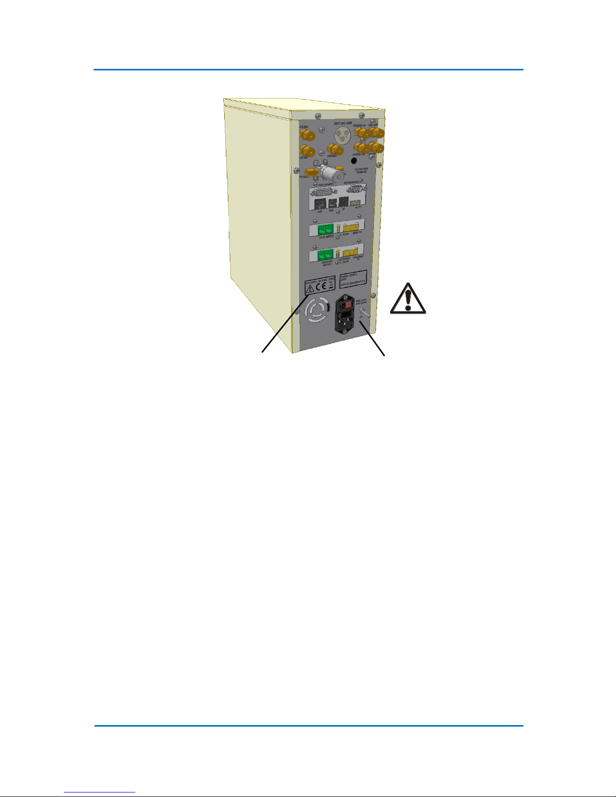
1.4 Warnings Signs
HIGH VOLTAGE: Disconnect power cable before removing any units cover.
1.5 Cryogenic Trap Precautions and Warnings
The following cautions and warnings relate to the cryotrap fitted to OPTIC-4SC and OPTIC-4DC.
1. The cryotrap cannot be used with a metal column. The metal column will short-circuit the
trap heater, causing severe damaged to the trap. A glass capillary pre-column is advised to
avoid problems.
2. It is strongly advised not to hold the trap at subambient temperature for longer than 20
minutes. The ice is formed on the points of column near the trap ends if trap is kept cold for
a long time. This penomenon can cause analytical problems and also can bring damage to
the column coating!
3. The cryotrap uses cryogenic liquids (CO2 and liquid nitrogen) to cool down trap to sub-
ambient temperatures. Personnel must be thoroughly familiar with properties and safety
considerations before being allowed to handle cryogenic liquids and the cryogenic trap.
4. Cryogenic liquids can cause serious burns. Hand protection and goggles (not safety glasses)
are to be worn at all times when handling it. Never allow any unprotected part of the body
to come in contact with un-insulated tubing or parts that contain cryogenic products. The
Warning
Label
Functional Earth
Terminal

OPTIC-4 User’s Guide
Issue 5.3
Precautions and Warnings
Page 1-5
extremely cold metal will cause the flesh to stick rapidly and tear when you attempt to
withdraw.
5. Cryogenic liquids, when returned to the gaseous state, can displace oxygen from the air
under the right conditions. It is strongly recommended to use and store cryogenic liquids in
well ventilated areas only. It may also be prudent to install oxygen monitors in areas where
liquid nitrogen is stored and ventilation is minimal.
6. The CO2 cooling option is supplied with a cryogenic valve that can hold maximum pressure
of 1000 psi. In order not to exceed this pressure limit, the CO2 cylinder must be kept at the
temperature not higher than 25 °C.
7. Dewar with liquid Nitrogen should be handled and stored in an upright position. Do not drop
Dewar or tip it on its sides.

OPTIC-4 User’s Guide
Issue 5.3
Precautions and Warnings
Page 1-6
1. Waarschuwingen en aandachtspunten
Dit hoofdstuk beschrijft de waarschuwingen die in acht dienen te worden genomen tijdens het
installeren en bedienen van de OPTIC-4.
Veiligheid informatie wordt behandeld op de relevante onderdelen in de handleiding. Lees eerst de
handleiding in zijn geheel voordat u een installatie of bediening gaat uitvoeren. Blijft er een punt
onduidelijk, neem dan altijd eerst contact op met uw leverancier.
1.1 Algemene OPTIC-4 waarschuwingen en aandachtspunten
De OPTIC-4 is ontwikkeld voor installatie en gebruik in een laboratorium omgeving door goed
geschoold personeel. Alle lokale relevante veiligheid aspecten moeten in acht worden genomen
voordat er aan de installatie van het instrument wordt begonnen.
1.1.1 Algemene OPTIC-4 waarschuwingen
1. De OPTIC-4 is bedoeld voor het gebruik in goed voorziene chemische analytische laboratoria.
Voor de opslag van oplosmiddelen moet een vlam dovende kast aanwezig zijn en het
personeel moet ten alle tijden beschermende kleding en bril dragen.
2. Zowel de GC en de OPTIC-4 moeten afgekoppeld zijn van de netspanning totdat de installatie
is afgerond. De OPTIC-4 moet worden aangesloten op een geaarde netspanning.
3. In de bedieningsunit van de OPTIC-4 zijn gevaarlijke hoogspanningen aanwezig. Schakel de
unit uit voordat u een van de zijplaten wilt verwijderen.
4. Voor de werking van de inlet is het nodig dat deze snel kan verwarmen naar hoge
temperaturen. De inlet kan enige tijd warm blijven nadat de unit is uitgeschakeld. Let goed
op wanneer er gewerkt word in de omgeving van de inlet. Het is vooral belangrijk dat de
inlet is afgekoeld tot een temperatuur lager dan 40°C en de unit is uitgeschakeld voordat er
liners worden gewisseld.
5. De meeste organische oplosmiddelen zijn giftig, de een meer dan de andere. Een
hoeveelheid damp van het oplosmiddel komt uit de “exhaust” port van de unit. Het is
aanbevolen deze dampen af te voeren via een afzuiging of op te vangen in een actief kool
filter. Hierbij is het wel van belang dat er geen restrictie optreed, waardoor de analyse wordt
beïnvloed.
6. De OPTIC-4 gas controle unit is niet ontworpen om te werken met explosieve, corrosieve en
giftige gassen (behalve Waterstof).
7. Het gebruik van waterstof als dragergas is kan gevaarlijk zijn vanwege de explosiviteit. Let
daarom extra goed op bij het gebruik van waterstof als draaggas bij een GC of GC/MS
systeem.

OPTIC-4 User’s Guide
Issue 5.3
Precautions and Warnings
Page 1-7
1.1.2 Algemene OPTIC-4 aandachtspunten
1. Het is van belang dat er een juiste verbinding wordt gemaakt tussen de inlet power kabels
en de inlet zelf. Een slechte verbinding kan een slechte werking veroorzaken en de
verbindingen kunnen extreem heet worden.
2. Tijdens het zoeken naar een lek is het van belang dat er gewerkt word met een geschikte
elektronische lekdetector. Onder geen enkele voorwaarde mag er een zeepoplossing of een
vergelijkbare oplossing worden gebruikt, dit zal de inlet vervuilen.
3. De inlet bedieningsunit mag niet worden aangezet wanneer de inlet niet is aangesloten, dit
kan onherstelbare schade aan de unit veroorzaken.
1.2 Waarschuwingen en aandachtspunten voor de OPTIC-4 Cryotrap
De volgende waarschuwingen en aandachtspunten zijn gerelateerd aan de OPTIC-4-SC en OPTIC-4DC.
1.2.1 Waarschuwingen voor de OPTIC-4 Cryotrap
1. De Cryotrap gebruikt vloeibare stikstof om koud gas te maken voor de lage
gebruikstemperaturen. De gebruiker moet goed bekend zijn met de eigenschappen en
veiligheidsregels voor het gebruik van vloeibare stikstof en de Cryotrap.
2. Vloeibare stikstof kan ernstige brandwonden veroorzaken. Handschoenen en een goed
aansluitende veiligheidsbril moeten te allen tijde gedragen worden wanneer er gewerkt
wordt met vloeibare stikstof. Zorg er voor dat de huid nooit in contact komt met een
ongeïsoleerde leiding van het cryo systeem. Het extreme koude metaal zorgt er voor dat de
huid aan het metaal plakt en wanneer men probeert los te komen trekt men de huid kapot.
3. Dewars (vat met vloeibare stikstof) dient men rechtop te vervoeren en te plaatsen. Gooi
nooit een Dewar om.
1.2.2 Aandachtspunten voor de OPTIC-4 Cryotrap
Zorg ervoor dat er een gas stroom door de warmtewisselaar loopt voordat deze in de vloeibare
stikstof wordt geplaatst of wanneer deze voor een langere tijd in de stikstof blijft staan. Dit is om te
voorkomen dat de warmtewisselaar bevriest door de aanwezigheid van water damp in de aanwezige
lucht.

OPTIC-4 User’s Guide
Issue 5.3
Precautions and Warnings
Page 1-8
1. Sicherheitshinweise und Warnungen
Dieses Kapitel enthält Erläuterungen zu den bei Installation und Betrieb von OPTIC-4 zu beachtenden
Sicherheitshinweisen und Warnungen.
Sicherheitshinweise werden an allen relevanten Stellen im Handbuch gegeben. Bitte lesen Sie dieses
Handbuch komplett durch, bevor Sie OPTIC-4 installieren oder in Betrieb nehmen. Bei etwaigen
Unklarheiten kontaktieren Sie bitte vor der Ingebrauchnahme Ihren Lieferanten.
1.1 OPTIC-4 - Allgemeine Sicherheitshinweise und Warnungen
OPTIC-4 wurde für die Installation und den Gebrauch durch entsprechend geschultes Personal in
Laboratorien entwickelt. Vor Installation und Ingebrauchnahme sind sämtliche relevanten
Sicherheitsaspekte unter Berücksichtigung der lokalen Vorschriften zu überprüfen.
1.1.1 OPTIC-4 - Allgemeine Warnungen
OPTIC-4 ist für die Benutzung in entsprechend ausgestatteten Laboratorien für chemische Analytik
entwickelt. Es ist sicherzustellen, dass Lösungsmittel in feuersicheren Behältnissen aufbewahrt
werden und Mitarbeiter zu allen Zeiten Schutzkleidung und Augenschutz tragen.
Sowohl OPTIC-4 als auch der GC sind von der Hauptstromzufuhr abzutrennen, solange die Anlage
noch nicht komplett installiert ist. OPTIC-4 ist an eine geerdete Steckdose anzuschließen.
Im Innern des OPTIC-4 Steuerteils befinden sich Teile mit potentiell gefährlicher Betriebsspannung.
Schalten Sie den Steuerteil ab und unterbrechen Sie die Hauptstromzufuhr, bevor Sie das Gehäuse
des Steuerteils entfernen.
Betrieb des Injektors erfordert, dass er schnell auf hohe Temperaturen erhitzt wird. Teile des
Injektors können noch heiß sein, nachdem das Teil abgeschaltet wurde. Beim Arbeiten in der Nähe
des Injektors ist Vorsicht geboten. Es ist sicher zu stellen, dass der Injektor (unter 40°C) abgekühlt
und ausgeschaltet ist, bevor die Injektor-Liner ausgewechselt werden.
Fast alle organischen Lösungsmittel sind bis zu einem gewissen Grad giftig. Da aus dem Auslassport
hohe Mengen an Lösungsmitteldämpfen austreten können, wird dringend empfohlen, diese Dämpfe
in eine Abzugshaube zu leiten oder einen Aktivkohlenfilter am Port anzubringen. Dadurch darf
jedoch der Fließvorgang durch diesen Port nicht beeinträchtigt werden um korrekten Verlauf der
Analyse zu gewährleisten.
Die OPTIC-4 Gaskontrollen sind nicht für Betrieb mit Explosivstoffen, (abgesehen von Hydrogen),
Schadgasen oder toxischen Gasen gedacht.
Der Gebrauch von Hydrogen als GC-Trägergas ist gefährlich. Beim Gebrauch von Hydrogen als GCTrägergas in einem GC- oder GC/MS-System besteht Explosionsgefahr – daher ist äußerste Vorsicht
geboten.

OPTIC-4 User’s Guide
Issue 5.3
Precautions and Warnings
Page 1-9
1.1.2 OPTIC-4 - Allgemeine Warnungen
Es ist wichtig, dass eine gute Verbindung zwischen dem Injektor-Niedrigspannungskabel und dem
Injektor hergestellt wird, da eine schlechte Verbindung die Leistung herabsetzen und die Verbindung
extrem heiß werden lassen kann.
Beim Überprüfen der Verbindungen auf Lecks sollte ein geeigneter elektronischer Leckdetektor oder
eine 50/50 Lösung aus -Propanol und Wasser benutzt werden. Keinesfalls Seifenlauge oder Ähnliches
benutzen, da dies den Injektor kontaminiert.
Der Steuerteil des Injektors darf nicht angeschaltet werden, solange der Injektor nicht angeschlossen
wurde, da dies das Instrument schwer beschädigen kann.
1.2 Sicherheitshinweise und Warnungen betreffend die OPTIC-4
Kühlfalle
Die folgenden Sicherheitshinweise und Warnungen betreffen die an OPTIC-4-SC und OPTIC-4-DC
angebrachte Kühlfalle.
1.2.1 Warnungen betreffend die OPTIC-4 Kühlfalle
Die Kühlfalle wird mit flüssigen Stickstoff betrieben um das kalte Gas für Niedrigtemperatur-Betrieb
zu erzeugen. Vor der Benutzung ist sicherzustellen, dass das Bedienungspersonal mit den
Eigenschaften flüssigen Stickstoffs und den Sicherheitsanforderungen betreffend die Kühlfalle
eingehend vertraut ist.
Flüssiger Stickstoff kann schwere Verbrennungen verursachen. Beim Umgang damit sind
grundsätzlich Handschutz und Vollsichtbrillen (keine Schutzbrillen) zu tragen. Ungeschützte
Körperteile dürfen keinesfalls mit nicht-lierten Leitungen oder Teilen in Kontakt kommen, die
Tieftemperaturprodukte enthalten, da die Haut unverzüglich am extrem kalten Metall kleben bleibt
und beim Zurückziehen abgerissen wird.
Dewarbehälter mit flüssigem Stickstoff sind senkrecht zu hantieren und zu lagern. Dewarbehälter
nicht fallen lassen oder umdrehen.
1.2.2 Warnungen betreffend die OPTIC-4 Kühlfalle
Stellen Sie sicher, dass Gas durch die Rohrschlange des Kühlfallen- Wärmetauschers fließt, wenn sie
ihn in den flüssigen Stickstoff tauchen oder für lange Zeit im Dewarbehälter lassen um Vereisung des
Wasserdampfes in der Luft zu verhindern, was den Gasfluss durch den Wärmetauscher
unterbrechen würde.

OPTIC-4 User’s Guide
Issue 5.3
Precautions and Warnings
Page 1-10
1. 注意事项与警告
本节将说明在安装或操作 OPTIC-4 时应当遵守的警告和注意事项。
安全信息已在手册的相关要点中进行说明。安装或操作仪器前,请完整阅读本手册。如有任何
疑点,请在操作前联系供应商以获取帮助。
备注:
警告、注意事项和其他相关事项的含义约定如下:
警告! 表示具有潜在危险,若不加以避免,可能导致中度至严重人身伤害或死亡。
小心! 表示具有潜在危险,若不加以避免,可能导致轻度人身伤害或设备损坏。
注意事项 强调额外信息,提供此类信息目的是确保合理正确使用此仪器。
1.1 一般注意事项与警告
4. OPTIC-4 仅用于分析指定的类型。
5. 请按照本手册中描述的流程进行操作。
6. 未经 GL Sciences B.V.或其授权代表批准,请勿改造或拆卸仪器,否则可能会形成安全
隐患。
1.2 安装注意事项与警告
OPTIC-4 专为在实验室环境中安装和使用而设计,由经过适当培训的人员操作。安装和调
试仪器前,所有相关的安全事宜均应当按照当地法规进行评估。
8. GL Sciences 代表必须履行仪器安装和配置职责。若仪器安装后必须移动,为防止发生
潜在损坏,应当联系 GL Sciences 代表。

OPTIC-4 User’s Guide
Issue 5.3
Precautions and Warnings
Page 1-11
9. OPTIC-4 设计用于配备了适当设施的分析实验室。分析中使用的溶剂为可燃、有毒溶剂。
请将仪器安装在通风良好的室内。贮存溶剂时必须采取预防措施,将其存放在防火柜
中,员工必须始终穿着防护服并佩戴护目用具。
10. OPTIC-4 控制器必须使用通地(接地)电源插座供电。
功率要求: 100-240V 交流单相,频率 50-60 Hz。
一般功率消耗: 150VA
最大功率消耗: 450 VA
11. OPTIC-4 控制器和主机 GC 均应当断开供电电源,直到设备安装完成。
12. Optic-4 控制器电源开关位于仪器后面。控制器后面应当留下足够的空间,以方便接触
电源开关。
13. 请勿使用非仪器配用电源线,否则可能导致火灾或触电。
14. 请务必保持进口电力电缆和进口电力终端之间的导电连接良好。连接不良可能导致难
以操作,且可能导致连接件过热。
周围环境: 温度范围: 18 - 40C
湿度: 40 - 70%
8. OPTIC-4 EFC 并非设计使用爆炸性气体(包括氢气)、腐蚀性气体或有毒气体进行操作。
载气: 氦气、氮气或氢气
供气压力: 300 - 700 kPa
含量: 99.995% 或以上
9. 将氢气用作 GC 载气时存在潜在危险,有可能发生爆炸。在 GC 或 GC/MS 系统中将氢气
用作 GC 载气时,应当格外小心。
10. OPTIC-4 进口通过压缩空气冷却。当气源压力超过规定的压力时,冷却阀可能受损。请
勿超过最大气源压力 700 kPa。
冷却空气: 无油无水压缩空气
供气压力: 700 kPa
1.3 操作注意事项与警告

OPTIC-4 User’s Guide
Issue 5.3
Precautions and Warnings
Page 1-12
10. 大多数有机溶剂都有一定的毒性。大量溶剂蒸汽可能从排气口排出。我们强烈建议,
使用管道将这些蒸汽输送到排气口配备的通风橱或活性碳阱。但是,不得限制气体从
此排气口排出,以免阻碍仪器的正常运行。
11. 当进行输气管道连接泄露测试时,应当使用适当的电子检漏仪。任何情况下都不能将
肥皂液或类似溶液用作电子检漏仪溶液,否则会污染进口和柱。
12. OPTIC-4 控制装置内存在潜在危险电压。为防止受到人身伤害和仪器损坏,不得拆卸或
改造仪器,亦不得进行内部维修。
13. 操作玻璃内胆时,请务必佩戴必要的防护眼镜,如果内胆因受到冲击而破裂或破碎,
可防止眼睛和皮肤受伤。
14. 操作毛细管柱时,请务必佩戴必要的防护眼镜,如果柱因受到冲击而破裂或破碎,可
防止眼睛受伤。
15. 操作 GC 进口时,进口需要迅速加热至高温。装置关闭或因内部故障而停机后,进口零
件的余温可能保持一段时间。在进口周围作业时,必须小心。更换进口内胆前,请务
必确保进口已冷却(低于 40°C)。
16. 当进口处于高温时,请勿拧紧或拧松顶部凸台或进口底部螺母。螺纹极易受损。
17. 当进口压力超过规定的压力时,OPTIC-4 EFC 可能会损坏。请勿超过最大气源压力 700
kPa。
1.4 警告标识
高压: 移除任何装置盖子前,请先断开电力电缆。
OPTIC-4 User’s Guide
Issue 5.3
Precautions and Warnings
Page 1-13
警告标记。 功能接地端子。
1.5 冷阱注意事项与警告
以下注意事项与警告涉及 OPTIC-4SC 和 OPTIC-4DC 配备的冷阱。
8. 冷阱不得与金属柱共同使用。金属柱会使冷阱加热器短路,造成冷阱严重损坏。建议
使用玻璃毛细管前置柱,以避免出现问题。
9. 冷阱使用低温液体(二氧化碳和液氮)冷却冷阱,使温度低于室温。员工必须完全熟
悉其特性和安全措施才可处理低温液体和冷阱。
10. 低温液体可能造成严重烧伤。处理低温液体时,员工应当始终佩戴防护手套和护目镜
(非安全眼镜)。严禁无保护措施的身体部位接触未绝缘的管子或包含低温产品的零
件。温度极低的金属会迅速粘住皮肤,如果您试图撤离,皮肤会撕裂。
11. 当低温液体恢复气态时,在合适的条件下,可取代空气中的氧气。强烈建议仅在通风
良好的区域使用和贮存低温液体。建议在贮存液氮的区域和通风不良的区域安装氧气
监测仪。

OPTIC-4 User’s Guide
Issue 5.3
Precautions and Warnings
Page 1-14
12. 二氧化碳冷却选项配备一个低温阀,可承受的最大压力达 1000 psi。为避免超过此压力
限制,二氧化碳瓶必须保存在温度低于 25°C 的环境中。
13. 含液氮的杜瓦瓶应当直立处理和贮存。不得使杜瓦瓶倒下或倾斜。

OPTIC-4 User’s Guide
Issue 5.3
Precautions and Warnings
Page 1-15
1. Mises en garde et précautions d'emploi
Cette section expose les mises en garde et les précautions d'emploi à observer lors de l'installation
ou du fonctionnement d'OPTIC-4.
Les informations relatives à la sécurité sont présentées en différents endroits du manuel lorsque ce
point s'impose. Nous vous prions donc de lire le manuel dans son intégralité avant d'installer ou de
faire fonctionner l'appareil. Si des points manquent de clarté, veuillez solliciter l'aide de votre
fournisseur avant de procéder à la mise en marche de l'appareil.
1.1 Mises en garde et précautions d'emploi générales concernant
OPTIC-4
OPTIC-4 est conçu pour être installé et utilisé en laboratoire par un personnel formé à cet effet. Tous
les aspects de la sécurité doivent être déterminés en fonction des règles en vigueur dans les lieux
concernés avant d'installer et de mettre en service l'appareil.
1.1.1 Mises en garde générales concernant OPTIC-4
OPTIC-4 est destiné à l'utilisation dans des laboratoires d'analyses chimiques correctement équipés.
Des dispositions doivent être notamment prises pour que les solvants soient entreposés dans un lieu
de rangement ininflammable et pour que le personnel porte en permanence des vêtements et des
lunettes de protection.
OPTIC-4 tout comme le GC hôte doivent être déconnectés du réseau électrique tant que l'installation
de l'appareil n'est pas terminée. OPTIC-4 doit être alimenté à partir d'une prise de terre.
Il peut y avoir des voltages dangereux présents dans l'unité de commande d'OPTIC-4. Eteignez l'unité
de commande et débranchez-la avant d'enlever le couvercle.
Le fonctionnement de l'injecteur implique son réchauffement rapide afin d'atteindre des
températures élevées. C'est pourquoi des éléments de l'injecteur peuvent rester très chauds une
fois celui-ci éteint. Il faut donc faire attention lorsqu'on travaille à proximité de l'injecteur. Il est
particulièrement important de s'assurer que l'injecteur est refroidi (au-dessous de 40°C) et éteint
avant de procéder à toute opération de remplacement.
La plupart des solvants organiques sont dans une certaine mesure toxiques et une quantité non
négligeable de vapeur de solvant peut sortir de la soupape d'échappement. Il est fortement
recommandé de faire en sorte que ces vapeurs soient canalisées vers une hotte d'aération ou un
filtre à charbon actif adapté à la soupape. Il ne faut toutefois pas restreindre l'évacuation qui se fait
par cette soupape, ceci risquant de fausser les analyses.
Les commandes de gaz d'OPTIC-4 ne sont pas conçues pour un fonctionnement avec des gaz
explosifs (à l'exception de l'hydrogène), corrosifs ou toxiques.

OPTIC-4 User’s Guide
Issue 5.3
Precautions and Warnings
Page 1-16
L'utilisation d'hydrogène en tant que gaz vecteur GC peut être dangereux puisqu'il s'agit d'un gaz
potentiellement explosif. Vous devez prendre des mesures de précautions extrêmes lorsque vous
utilisez de l'hydrogène en tant que gaz vecteur dans le système GC ou GC/SM.
1.1.2 Précautions d'emploi générales concernant OPTIC-4
La qualité du raccordement entre le câble électrique de l'injecteur et l'injecteur et très importante.
Une mauvaise connexion peut entraîner un mauvais fonctionnement ainsi qu'un échauffement
extrême de celle-ci.
Pour les tests de détections de fuites sur les connexions, utilisez un détecteur de fuite électronique
approprié ou une solution 50/50 d'propanol et d'eau. Il ne faut en aucun cas utiliser une solution
savonneuse ou une solution semblable qui contaminera l'injecteur.
La boîte de commande de l'injecteur ne doit pas être allumée lorsque l'injecteur est déconnecté sous
peine de grandement endommager l'appareil.
1.2 Mises en garde et précautions d'emploi concernant le piège
cryogénique d' OPTIC4
Les mises en garde et précautions d'emploi suivantes concernent le piège cryogénique dont sont
équipés OPTIC-4-SC et OPTIC-4-DC.
1.2.1 Mises en garde concernant le piège cryogénique d'OPTIC-4
Le piège cryogénique utilise de l'azote liquide pour produire le gaz froid nécessaire aux opérations à
basses températures. Le personnel devra connaître parfaitement les propriétés et les mesures de
sécurité avant d'être autorisé à manipuler l'azote liquide et le piège cryogénique.
L'azote liquide peut causer de graves brûlures. Il faut donc porter des gants et des lunettes à
pourtour étanche (et non pas de simples lunettes de protection) tout le temps qu'on utilise ce
produit. Il ne faut jamais laisser une partie non protégée du corps entrer en contact avec des tuyaux
non lés ou avec des éléments contenant des produits cryogéniques. La température extrêmement
froide du métal fera que la peau y adhérera et se déchirera lorsqu'on tentera de se dégager.
Les dewars contenant de l'azote liquide devront être manipulés et entreposés en position verticale.
Il ne faut pas laisser tomber les dewars ou les basculer sur le côté.
1.2.2 Précautions d'emploi concernant le piège cryogénique d'OPTIC-4
Assurez-vous que le gaz circule bien dans le serpentin de l'échangeur thermique du piège
cryogénique lorsque vous l'immergez dans l'azote liquide ou lorsque vous le laissez longtemps dans
le dewar. Ceci afin d'éviter que la vapeur d'eau présente dans l'air ne givre ce qui bloquerait la
circulation du gaz dans l'échangeur thermique.

OPTIC-4 User’s Guide
Issue 5.3
Precautions and Warnings
Page 1-17
1. Advertencias y precauciones
En esta sección se explican las advertencias y precauciones que deben observarse a la hora de
instalar o manipular el OPTIC-4.
A lo largo del manual existen distintos apartados que contienen información relacionada con la
seguridad. Así, pues, le recomendamos que lea detenidamente todo el manual antes de instalar o
manipular el instrumento. Si tras su lectura tuviese alguna duda, le rogamos que se ponga en
contacto con su proveedor.
1.1 Advertencias y precauciones generales relacionadas con el OPTIC-4
OPTIC-4 está diseñado para que se instale y utilice en un laboratorio por personas
convenientemente capacitadas. Antes de instalarlo o ponerlo en funcionamiento es imprescindible
que se valoren los aspectos relativos a la seguridad en el contexto de las normas locales.
1.1.1 Advertencias generales en torno al OPTIC-4
OPTIC-4 debe utilizarse en laboratorios de análisis de sustancias químicas debidamente equipados y,
en este sentido, es necesario tomar medidas para almacenar los dlventes en armarios refractarios y
para que el personal lleve ropa protectora y gafas en todo momento.
Hasta que finalice la instalación es imprescindible desconectar de la toma eléctrica tanto el OPTIC-4
como el GC huésped. En cuanto al OPTIC-4 es necesario que reciba la corriente de una toma con
conexión a tierra.
La unidad de control del OPTIC-4 contiene varias tensiones potencialmente peligrosas, por lo que
antes de retirar la cubierta es necesario desconectar la unidad de control y también la fuente de
alimentación eléctrica.
Para que el inyector funcione adecuadamente es necesario que se caliente rápidamente y alcance
altas temperaturas. Se prestará mucha atención cuando se trabaje en la zona del inyector pues sus
piezas podrían seguir estando calientes tiempo después de haber desconectado la unidad. Es
especialmente importante asegurarse de que el inyector esté frío (por debajo de los 40°C) y
desconectado antes de cambiar los revestimientos del inyector.
La mayoría de los dlventes orgánicos son relativamente tóxicos y es posible que salgan vapores por
el orificio de escape. Se recomienda encarecidamente dirigir dichos vapores a una campana de
humos o instalar un separador de carbono activo en el orificio. Por otro lado, conviene no restringir
el flujo a través del orificio puesto que algo así podría interferir en los análisis.
Los controles de gases del OPTIC-4 no están pensados para trabajar con gases explosivos (aparte de
hidrógeno), corrosivos o tóxicos.

OPTIC-4 User’s Guide
Issue 5.3
Precautions and Warnings
Page 1-18
La utilización de hidrógeno como gas portador de GC es, en principio, peligroso dada su explosividad.
Se debe prestar sumo cuidado y atención cuando se utilice hidrógeno como gas portador de GC en
un sistema GC/MS.
1.1.2 Precauciones generales OPTIC-4
Es importante que la conexión entre el cable eléctrico del inyector y el inyector sea buena, de lo
contrario, el funcionamiento no sería óptimo y, además, la conexión podría calentarse en exceso.
Cuando se realicen pruebas de fugas en las conexiones se utilizará un detector de fugas electrónico
adecuado o una solución al 50% de propanol y agua. En ningún caso se utilizará solución jabonosa o
un producto similar ya que contaminaría el inyector.
No debe conectarse la caja de control del inyector cuando éste esté desconectado dado que se
dañaría gravemente el instrumento.
1.2 Advertencias y precauciones relacionadas con el crioseparador
OPTIC-4
Las advertencias y precauciones siguientes guardan relación con el crioseparador instalado en el
OPTIC-4 y el OPTIC-4-DC.
1.2.1 Advertencias relacionadas con el crioseparador del OPTIC-4
El crioseparador utiliza nitrógeno liquido para producir el gas frío necesario para que el instrumento
funcione a baja temperatura. Es esencial que el personal esté debidamente familiarizado con las
propiedades y las consideraciones en torno a la seguridad antes de que manipulen el nitrógeno
líquido y el crioseparador.
El nitrógeno líquido puede provocar graves quemaduras, de ahí que sea necesario portar en todo
momento cuando se manipule gafas protectoras (no gafas de seguridad) y guantes. Nunca permitir
que zonas desnudas del cuerpo entren en contacto con tuberías no aisladas o piezas que puedan
contener productos criogénicos. El metal extremadamente frío hará que la piel se pegue
rápidamente, rasgándola cuando se intente separarla.
Los frascos Dewar con nitrógeno liquido se manipularán y almacenarán en posición vertical. No
verterlos ni volcarlos sobre los costados.
1.2.2 Precauciones relacionadas con el crioseparador del OPTIC-4
Es necesario asegurarse de que el gas esté fluyendo a través de la bobina del tubo del
termointercambiador del crioseparador cuando se sumerja o saque del nitrógeno líquido. Con esta
medida se pretende evitar que se congele el vapor de agua presente en el aire, lo cual bloquearía el
flujo de gas a través del citado termointercambiador.

OPTIC-4 User’s Guide
Issue 5.3
Precautions and Warnings
Page 1-19
1. Avvertenze e precauzioni
In questo paragrafo vengono esposte le avvertenze e le precauzioni da osservare per l’istallazione e
il funzionamento dell’ OPTIC-4.
Lungo tutto il manuale vengono trattati gli aspetti essenziali dell’informazione per la sicurezza. Si
prega gentilmente di leggere tutto il manuale prima di procedere all’istallazione e al funzionamento
dell’apparecchio. Se qualche punto dovesse rimanere poco chiaro, si prega di prendere contatto col
vostro fornitore per dei chiarimenti prima di procedere.
1.1 Avvertenze e precauzioni generali dell’ OPTIC-4
L’OPTIC-4 é stato progettato per essere istallato e usato in un ambiente di laboratorio da personale
adeguatamente preparato. Tutti gli aspetti relativi alla sicurezza devono essere in accordo alle
norme locali prima che si proceda all’istallazione e alla commisione dell’apparecchio.
1.1.1 Avvertenze generali dell’ OPTIC-4
L’OPTIC-4 é stato creato per essere usato in laboratori di analisi chimica appropriatamente
equipaggiati. In particolare, devono essere presi dei provvedimenti riguardo al magazzinaggio dei
solventi che vanno conservati in mobili anti-infiammabili e al personale che deve sempre indossare
degli indumenti e degli occhiali di protezione.
Sia l’OPTIC-4 che l’host GC non devono essere collegati ai principali generatori di corrente fino a
ultimazione dell’istallazione dell’apparecchiatura. L’OPTIC-4 deve essere alimentato da una presa
interrata.
All’interno dell’unità di controllo dell’OPTIC-4 sono presenti dei voltaggi potenzialmente pericolosi.
Prima di rimuovere il coperchio dell’unità di controllo spegnere l’unità di controllo e disinserire i
principali alimentatori di corrente.
La messa in funzione dell’iniettore richiede un riscaldamento rapido fino al raggiungimento di
temperature elevate. Parti dell’iniettore potrebbero rimanere calde anche molto tempo dopo lo
spegnimento dell’unità. Bgna procedere con cautela quando si lavora attorno all’area dell’iniettore.
Prima del cambio dei rivestimenti dell’iniettore (liners) bgna assicurarsi che questi si sia raffreddato
(al di sotto dei 40°C) e che sia spento.
La maggior parte dei solventi organici sono relativamente tossici e una notevole quantità di questi
vapori potrebbero fuoriuscire dall’orificio di scarico. Si consiglia vivamente di canalizzare questi
vapori in un cappuccio del vapore, oppure di
applicare una presa del carbonio attivo all’orificio di scarico. Ad ogni modo il flusso attraverso
l’orificio di scarico non deve essere impedito in quanto cio potrebbe interferire con le analisi.

OPTIC-4 User’s Guide
Issue 5.3
Precautions and Warnings
Page 1-20
I sistemi di controllo dei gas dell’OPITIC 3 non sono stati progettati per procedimenti con esplosivi
(eccetto l’idrogeno), gas corrosivi o tossici.
L’uso dell’idrogeno come gas trasportatore GC é pericoloso in quanto per sua natura potenzialmente
esplosivo. Procedere con estrema cautela durante l’uso dell’idrogeno come gas trasportatore GC in
un sistema GC o GC/MS.
1.1.2 Precauzioni generali dell’ OPTIC-4
E’ importante collegare bene il cavo elettrico dell’iniettore all’iniettore. Un collegamento sbagliato
puo causarne il cattivo funzionamento e un surriscladamento dello stesso collegamento.
Quando si effettua una prova per la rilevazione di perdite dei collegamenti, fare uso di un rivelatore
di perdite elettronico oppure di una soluzione al 50/50 di -propanolo e acqua. In nessun caso va
usata una soluzione detergente o dello stesso tipo in quanto cio contaminerebbe l’iniettore.
La cassetta di controllo dell’iniettore non deve essere accesa quando l’iniettore é staccato in quanto
cio potrebbe danneggiare seriamente la strumentazione.
1.2 Avvertenze e precauzioni relative al cryotrap dell’OPTIC-4
Le seguenti avvertenze e precauzioni riguardano il cryotrap inserito all’OPTIC-4-SC e all’OPTIC-4-DC.
1.2.1 Avvertenze relative al cryotrap dell’OPTIC-4
Il cryotrap fa uso di azoto liquido per la produzione di gas freddo per operazioni a basse
temperature. Il personale addetto deve essere a conoscenza delle proprietà e delle considerazioni di
sicurezza prima di essere autorizzato all’uso dell’azoto liquido e del cryotrap.
L’azoto liquido puo causare delle gravi bruciature. Indossare sempre delle protezioni per le mani e
degli occhiali di protezione (non usare degli occhiali di sicurezza) durante il suo maneggiamento. Non
permettere a nessuna parte del corpo non protetta di entrare in contatto con la tubazione non lata o
delle parti che contengano prodotti criogenici. La temperatura estremamente fredda del metallo
causa l’aderenza immediata della pelle ad esso e lo strappo nel tentativo di rimuoverla.
I dewars di azoto liquido dovrebbero essere maneggiati e conservati in posizione eretta. Non lasciar
cadere i dewars o inclinarli di lato.
1.2.2 Precauzioni relative all’OPTIC-4 cryotrap
Assicurarsi che vi sia del gas che scorre lungo la bobina del tubo dello scambiatore di calore del
cryotrap quando lo si immerge nell’azoto liquido o lo si lascia nel dewar per molto tempo. Tale
precauzione va presa per evitare il congelamento del vapore acqueo presente nell’aria, che
bloccherebbe la fuoriuscita del gas attraverso lo scambiatore di calore.
 Loading...