

Page 1
Instruction Manual
from software ver sion 1.07
(Instruction version 1.01)
e-mail: service@glp.de
Internet: http://www.glp.de
Page 2

GLP German Light Products GmbH (Instruction version 1.01) / from software version 1.07 2
Notes:
Page 3

GLP German Light Products GmbH (Instruction version 1.01) / from software version 1.07 3
Table of content
1 Description of Device............................................................................................. 4
1.1 Safety Instructions............................................................................................5
2 Preparation and Installation .................................................................................. 6
2.1 Mounting..........................................................................................................6
2.1.1 Mounting on the floor (upright).............................................................. 6
2.1.2 Mounting in hanging position (Head down)...........................................7
2.1.3 Mounting in a sideway Position.............................................................7
2.2 Securing the Device......................................................................................... 8
2.3 Connections..................................................................................................... 8
2.3.1 Power Supply........................................................................................8
2.3.2 NEUTRIK
®
powerCON ......................................................................... 8
2.3.3 DMX...................................................................................................... 9
3 The Menu Field ....................................................................................................... 9
4 DMX Channel Selection (DMX Protocol)............................................................. 12
5 Changing Gobos...................................................................................................18
5.1 General remarks for changing gobos............................................................. 18
5.2 Changing rotating gobos (wheel 1) ................................................................ 19
6 Maintaining and Cleaning the VVOOLLKKSSLLIICCHHTT SSPPOOTT ........................................... 19
6.1 Safety regulations.......................................................................................... 20
6.2 Circumference and Interval (rule-of-thumb) ................................................... 20
7 Technical Specifications...................................................................................... 21
8 System dimensions (in mm)................................................................................ 22
9 Index...................................................................................................................... 25
Page 4
GLP German Light Products GmbH (Instruction version 1.01) / from software version 1.07 4
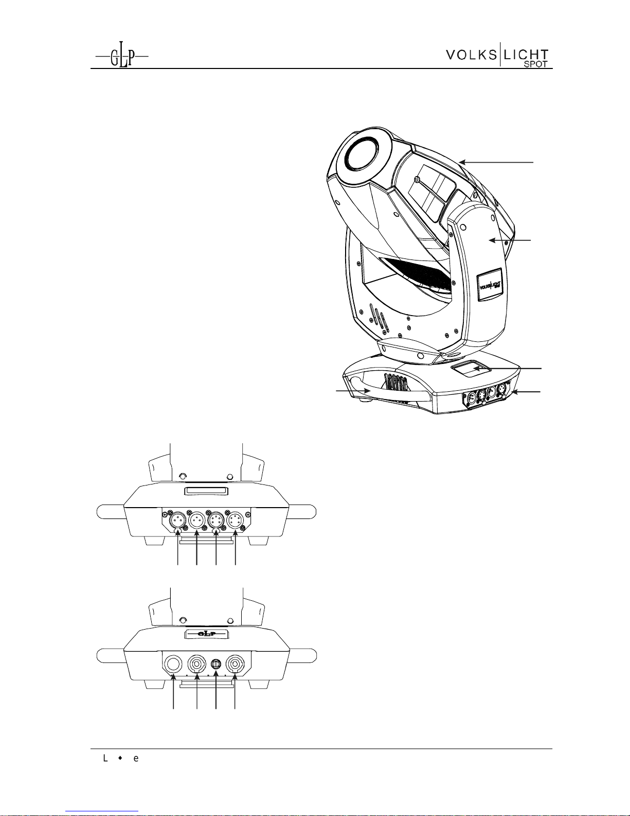
1 Description of Device
1. Moving head (actively cooled)
2. Arm with various cooling vents
3. LCD-Display/Menu (data entry)
4. Base with various connectors and
Camlock mounting system
5. Carrying handle. Also used to
attach the safety cable
123
4
5
6
7
8
9
10
11
12
13
6. DMX- Output (3 pin)
7. DMX- Input (3 pin)
8. DMX- Output (5 pin)
9. DMX- Input (5 pin)
10. Power On-/Off
11. Power-In (powerCON/blue)
12. Micro-fuse 5x20mm, T5A
13. Power-Out (powerCON/grey)
Page 5
GLP German Light Products GmbH (Instruction version 1.01) / from software version 1.07 5
1.1 Safety Instructions
The VVOOLLKKSSLLIICCHHTT SSPPOOTT is a High-Tech Product. To guarantee
a smooth operation, it is necessary to respect the following rules.
The manufacturer of this device will not take responsibility for
damages through any disregard of the information provided in
this manual. Warranty claims also will be voided in the case that
the fixture housing is opened.
1. Before powering on the fixture, make sure that the fixtures fans and air
inlets are clean and not blocked.
2. Ensure that the fixture head can rotate unhindered throughout its complete
range of pan and tilt movement. A safety distance of at least 0.5 m must be
maintained between the fixture and any easily inflammable material (e.g.
decoration material).
3. Attention! Don’t touch the fixture during the operation. This can cause
injuries and/or damages.
4. It is necessary to wait at least 15 minutes after disconnecting the mains
power before handling the fixture.. Pay attention to possible hot parts of the
fixture. -- Danger of BURNING --
5. Use only one DMX Input / Output at the same time.
6. Never look directly into the beam of light or into one of the LEDs.
Never use optical apertures to observe the beam of light. LED Class 2M.
You'll risk serious injury of your eyes and in particular of your retina.
Attention: LED Class 2M
can cause injuries of your eyes even
without optical instruments in front of them or within a distance of
less than 0.5m and short exposure time.
Hence: Avoid direct radiation into your eyes!
7. To ensure safe operation, follow also the Installation guide described in
chapter 2. Operating the VVOOLLKKSSLLIICCHHTT SSPPOOTT without suitable safety aids
like Safety cables or clamps/hooks can increase the risk of an accident and
must be avoided.
8. Repair, maintenance, and installation work shall be done by qualified or
GLP certified staff only. You need to pay attention to the common rules of
technology that are not explicitly mentioned in this manual.
9. Use only original GLP spare parts. Any structural modification of the system
will terminate all warranty claims.
10. Please keep this instruction manual for future reference.
Page 6
GLP German Light Products GmbH (Instruction version 1.01) / from software version 1.07 6
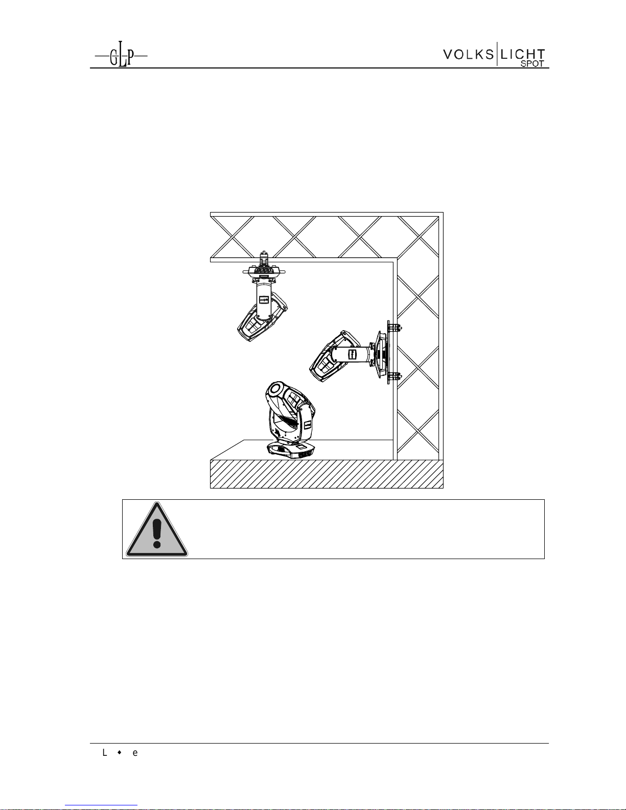
2 Preparation and Installation
2.1 Mounting
The VVOOLLKKSSLLIICCHHTT SSPPOOTT is fully operational whether it hangs or is mounted to
a wall. It can also be operated while standing on the floor. Keep a safety
distance of 0.5 m from any easily inflammable materials (decoration etc.).
Pay attention to the regulations of: BGV C1 (former VBG 70),
DIN VDE 0711-217 and BGI 810-3.
The installation shall be done by qualified staff only.
For the various mounting positions of the VVOOLLKKSSLLIICCHHTT SSPPOOTT (standing on the
floor, sideways or hanging) different accessories kits are available. Using any
required kits, along with the standard mounting connectors on the base of the
fixture, will ensure a safe and firm installation.
2.1.1 Mounting on the floor (upright)
The VVOOLLKKSSLLIICCHHTT SSPPOOTT is equipped with four robust rubber feet. This
allows a firm and safe stand on even surfaces.
Page 7
GLP German Light Products GmbH (Instruction version 1.01) / from software version 1.07 7
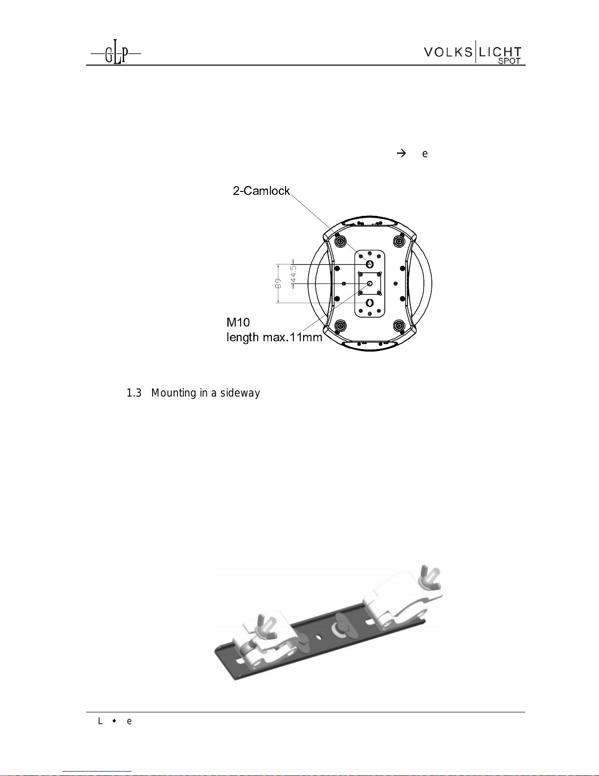
2.1.2 Mounting in hanging position (Head down)
To operate the VVOOLLKKSSLLIICCHHTT SSPPOOTT in an hanging position, please
attach one half-coupler centrically with a M10 thread bolt (max. length 11
mm). You can also use a dedicated mounting plate which is attached to
the fixture through two Camlock quick connectors see section below.
2-Camlock
M10
length max.11mm
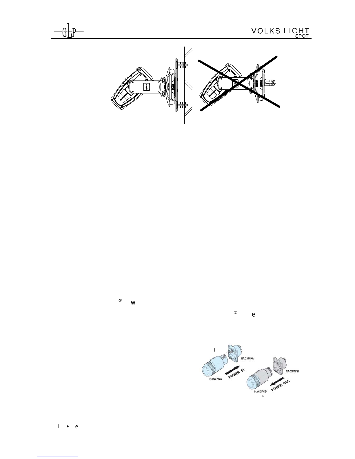
2.1.3 Mounting in a sideway Position
To operate the VVOOLLKKSSLLIICCHHTT SSPPOOTT in a sidewise position, please use
the dedicated mounting plate which is attached to the fixture two
Camlock quick connectors.
This technique is necessary to cope with the torque which accrues in this
mounting position. In addition it allows a concentrically position between
two truss belts. Never use the "Mounting in hanging position" technique
described above to secure the fixture in a sideway position, as the
fixtures base can become damaged, and a secure installation cannot be
assured.
Page 8
GLP German Light Products GmbH (Instruction version 1.01) / from software version 1.07 8
2.2 Securing the Device
Regardless of the mounting method of the VVOOLLKKSSLLIICCHHTT SSPPOOTT you'll have to
use a stipulated safety wire. Swipe it through one of the two handles of the
fixture and connect it to the primary support structure. Pay attention to a safe
and proper fastening. The safety cable must comply with BGI 810-3 (EN 605982-17 Section 17.6.6) and be capable of bearing a static suspended load that is
ten times the weight of the fixture and all installed accessories.
2.3 Connections
2.3.1 Power Supply
~100-240 Volt AC, 50-60 Hz, earth contact type plug, via Powercon
Connected load 400 VA (W) <=> T5A (micro-fuse 5x20mm)
Please see printing on the case for the right electronic supply!
Disconnect from the mains supply for changing the fuse and use
only the above described micro-fuse type.
2.3.2 NEUTRIK® powerCON
The VVOOLLKKSSLLIICCHHTT SSPPOOTT is fitted with NEUTRIK
®
powerCON locking 3
conductor AC connectors. Up to max. 11 fixtures can be linked via the
power outlets staying within the power limits of the 20A of the
connectors.
Note: Regional regulations and
limits might be lower and differ
from that.
Picture: Courtesy of NEUTRIK® AG
grey
Page 9

GLP German Light Products GmbH (Instruction version 1.01) / from software version 1.07 9
2.3.3 DMX
USITT DMX-512 Standard input/output in 3 & 5 pin connectors.
3 pin: Pin 1 = [Ground] / Pin 2 = [-] / Pin 3 = [+]
5 pin: Pin 1 = [Ground] / Pin 2 = [-] / Pin 3 = [+] / Pin 4/5 n.c.
The DMX- Addressing starts at the DMX- Address [001].
3 The Menu Field
You'll find the illuminated control board on the uppe r side of
the base. It allows you to make all necessary adjustments
of the system.
The current DMX address will be shown on the top level of
the menu. Use the Enter-key to adjust the DMX address or
press the Menu-key to reach the next level of the menu
where other settings can be made.
Menu Enter
1
DMX Start Address
With the Enter-key you reach the main menu. Afterwards
you can navigate through the menu with the Up/Down-
keys. Push the Enter-key to get in the next menu level or
to confirm your settings. Adjust them and set functions
ON/OFF with the Up/Down-ke ys. Confirm and save it with
the Enter-key (the display shows OK).
Use the Back-key to cancel the entry and to go back to the
main menu.
Back DownUP Enter
DMX Start Address
Reset
Special
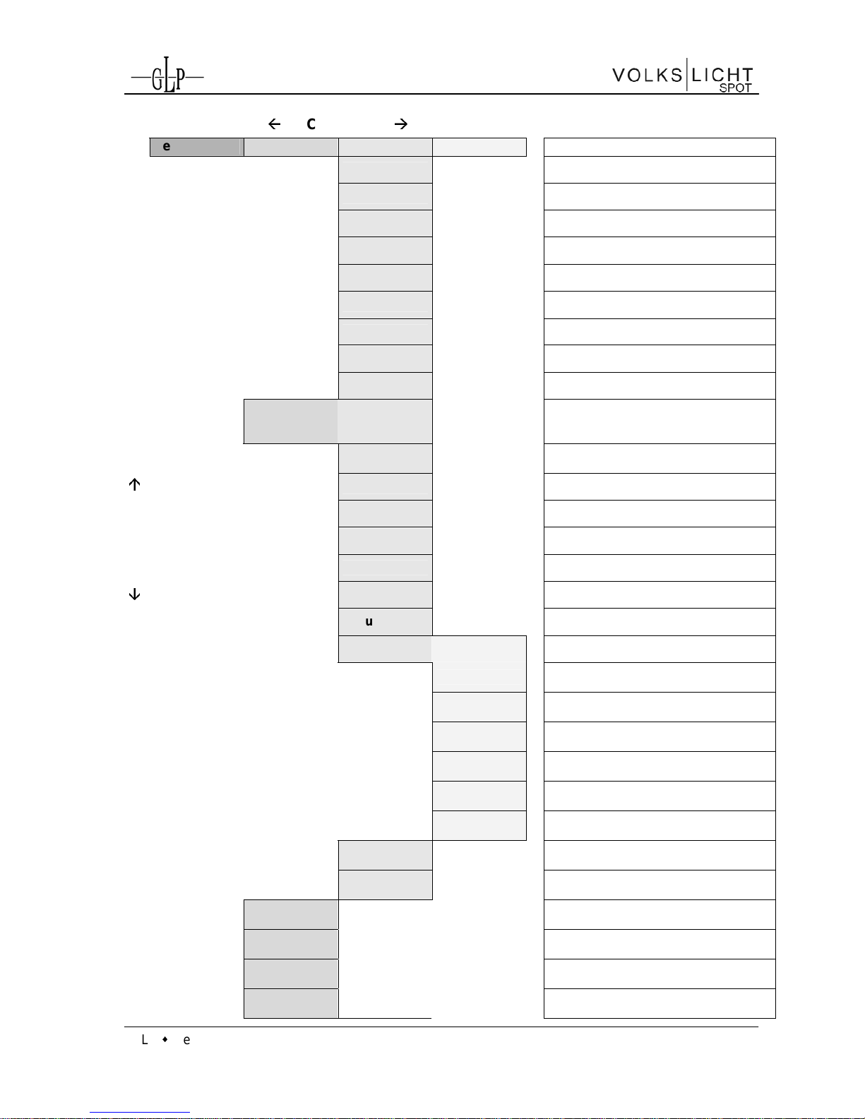
VOLKSLICHT Menü
BACK - ENTER
Level1 Level 2 Level 3 Level 4
Remark
DMX Start
Address
Define the DMX start address
Special Manual DMX
Manual control of all system functions
Pan
Manual control for Pan (X-movement)
Iris
Manual control for the Iris
Focus
Manual control for the Focus
Gobo2
Manual control for the Gobo 2
Rot Gobo 1
Manual control for the rotation of Gobo
1
Gobo 1
Manual control for the Gobo 1
P/T Speed
Manual control for Pan/Tilt Speed
DOWN - UP
P/T
Movement
Manual control for Pan/Tilt Movement
Page 10
GLP German Light Products GmbH (Instruction version 1.01) / from software version 1.07 10
BACK - ENTER
Level1 Level 2 Level 3 Level 4
Remark
Special
Manual control for special
White Temp
Manual control for White Temperature
Dimmer
Manual control for the Dimmer
Shutter
Manual control for the Shutter
Blue
Manual control for blue
Green
Manual control for green
Red
Manual control for red
Color Wheel
Manual control for the color wheel
Tilt
Manual control for Tilt (Y-movement)
Adjust
Key code
xxxx
Use the code for entering the
calibration menu (for authorized
persons only)
Display
Contrast
Adjustment of the Display contrast
Pan Offset?
Calibration of the Pan-Offset
Tilt Offset?
Calibration of the Tilt-Offset
Gobo 2
Calibration of the Gobo 2-Offset
Gobo 1
Calibration of the Gobo 1-Offset
Prism
Calibration of the Prism-Offset
DOWN - UP
Focus
Calibration of the Focus-Offset
LED Adjust
White Ad j. Red
Calibration of Red for a uniform White
(white balance)
Offset Adj.
Blue
Calibration of Blue offset
Offset Adj.
Green
Calibration of Green offset
Offset Adj.
Red
Calibration of Red offset
White Adj.
Blue
Calibration of Blue for a uniform White
(white balance)
White Adj.
Green
Calibration of Green for a uniform
White (white balance)
Clear
EEPROM
Erase EEPROM memory
Diagnose
Diagnose functions (For authorized
service only)
Temperature
Head
Reads out the temperature of the head
Default Full
Feature
Resets all functions to their default
values
Display Black
out
Auto switch-off display illumination after
10 seconds
DMX Hold
"Holds" last DMX signal in case of
signal loss
Page 11

GLP German Light Products GmbH (Instruction version 1.01) / from software version 1.07 11
BACK - ENTER
Level1 Level 2 Level 3 Level 4
Remark
Set DMX
Image
Set Image if
DMX off
Activates a stored scene if DMX is off
Save Image in
Memory
Stores the scene currently sent to the
unit
DMX Monitor
Indicates the presently received DMX
signal per DMX channel
Pan
Instantaneous value for Pan
Iris
Instantaneous value for Iris
Focus
Instantaneous value for Focus
Gobo2
Instantaneous value for Gobo 2
Rot Gobo 1
Instantaneous value for Rotating Gobo
1
Gobo 1
Instantaneous value for Gobo 1
P/T Speed
Instantaneous value for Pan/Tilt Speed
P/T
Movement
Instantaneous value for Pan/Tilt
Movement
Special
Instantaneous value for Special
White Temp
Instantaneous value for White
Temperature
Dimmer
Instantaneous value for Dimmer
Shutter
Instantaneous value for Shutter
Blue
Instantaneous value for Blue
Green
Instantaneous value for Green
Red
Instantaneous value for Red
Color Wheel
Instantaneous value for Color Wheel
Tilt
Instantaneous value for Tilt
Self Test
Program
Initiates a self-test program
Live Time
Indicates the overall operation time of
the system
Set DMX
Mode
Select the desired DMX Mode
Normal
Fixture works in "Normal" mode
High Res.
Fixture works in "High Resolution"
mode
Compressed
Fixture works in "Compressed" mode
Position
Feedback
On/Off
Reverse Pan
ON/OFF: Invert Pan movements
Reverse Tilt
ON/OFF: Invert Tilt movements
Page 12
GLP German Light Products GmbH (Instruction version 1.01) / from software version 1.07 12
BACK - ENTER
Level1 Level 2 Level 3 Level 4
Remark
Reset
RESET and new calibration for all
fixture funct ions
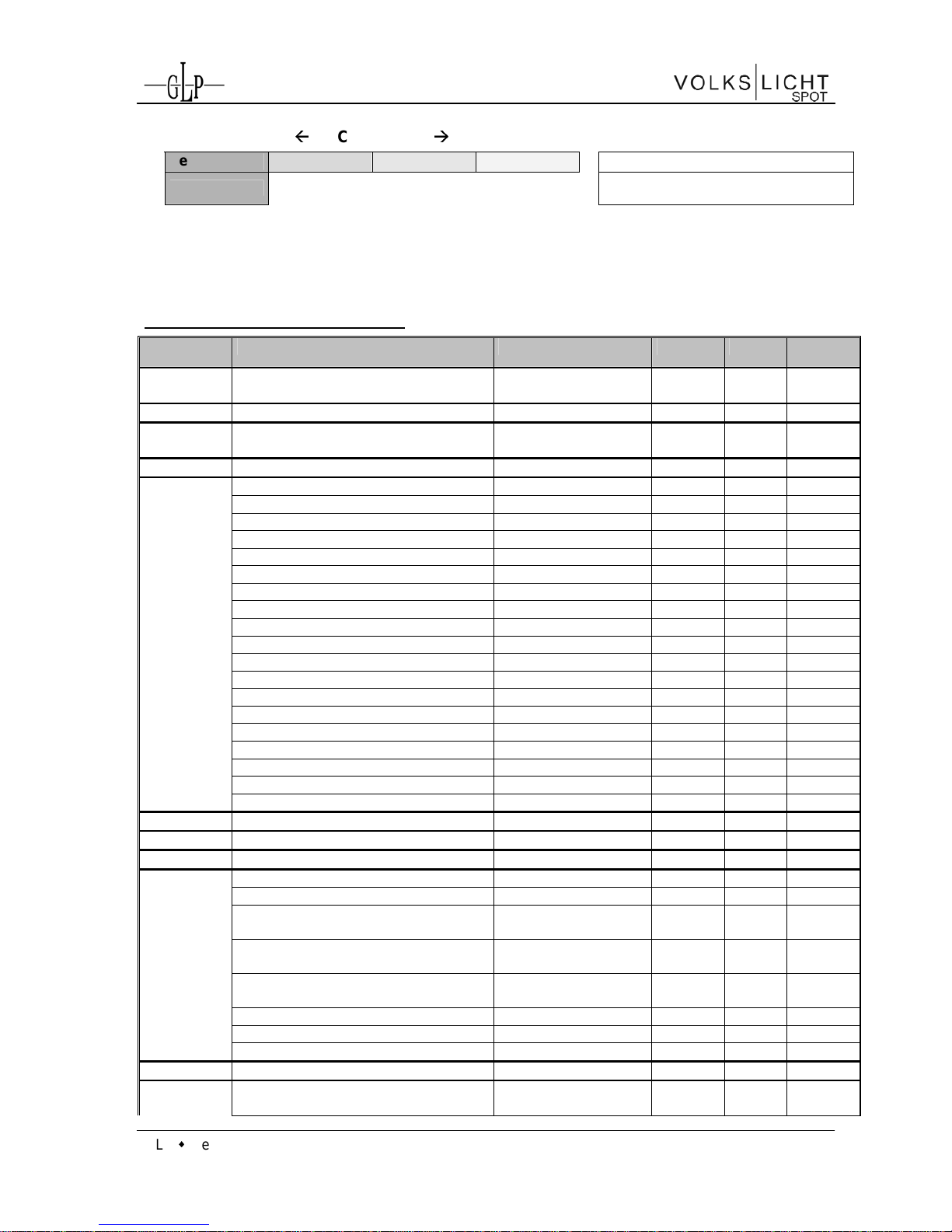
4 DMX Channel Selec tion (DMX Protocol)
Normal-Mode 20 DMX channels
Channel Function Time and Value DMX HEX %
1) PAN coarse
0 .. 660° 0..255 00..FF 0..100
2) PAN-fine
High- Pos ... High- P os + 2,6° (16 Bi t) 0..255 00..FF 0..100
3) Tilt coarse
0 .. 300° 0..255 00..FF 0..100
4) Tilt-fine
High- Pos … High- Pos + 1,2° (16 Bit) 0. .255 00..FF 0..100
5) Color
Colors adjustable v ia RGB 0..7 00..07 0..2,5
(fixed)
Color 01 - Red
1)
8..15 08..0F 3..5,5
Color 02 - Amber 1) 16..23 10..17 6..8,5
Color 03 - Warm Yellow 1) 24..31 18..1F 9..12,5
Color 04 - Yellow 1) 32..39 20..27 13..15,5
Color 05 - Green 1) 40..47 28..2F 16..18,5
Color 06 - Turquoise 1) 48..55 30..37 19..21,5
Color 07 - Cyan 1) 56..63 38..3F 22..24,5
Color 08 - Blue 1) 64..71 40..47 25..27,5
Color 09 - Lavender 1) 72..79 48..4F 28..30,5
Co lor 10 - Mauve 1) 80..87 50..57 31..34,5
Color 11 - Magenta 1) 88..95 58..5F 35..37,5
Color 12 - Pi nk 1) 96..103 60..67 38..40,5
White - CTO 104..111 68..6F 41..43,5
White 112..119 70..77 44..46,5
White - CTB 120..127 78..7F 47..49,5
Rainbow Effect Stop 2) 128 80 50
Rainbow Effect
3)
slow - fast 129. .223 81..DF 51..88
Rainbow Effect, random colors slow - fast 224.255 E0..FF 89..100
6) Red
Color mixing system - Red 0 - 100% 0..255 00..FF 0..100
7) Green
Color mixing system - Green 0 - 100% 0..255 00..FF 0..100
8) Blue
Color mixing system - Blue 0 - 100% 0..255 00..FF 0..100
9) Shutter
Shutter closed 0..15 00.. 0F 0..5,5
Random Pulse effect
4)
slow - fast 16..47 10.. 2F 6..18,5
Up-dimming then S hutt er cl osi ng
(random patterns)
4)
slow - fast 48..79 30.. 4F 19..31
Shutter open then down-dimming
(random patterns)
4)
slow - fast 80..111 50..6F 32..43
Up-dimming then down-dimming
(random patterns)
4)
slow - fast 112. .143
70..8F 44..56
Strobe effect pause 5s .. 1s 144..199
A0..C7 57..77
Strobe effect, slow - fast 1 Hz .. 10 Hz 200..239
C8..EF 78..94
Shutter open 240..255 F0..FF 94.4..100
10) Dimmer
Dimmer 0 - 100% 0..255 0..FF 0..100
11) Color
temp.
Continuous color temperature
correcti on between 10000k - 2500k
Applicable for ALL
colors
0..255 0..FF 0..100
Page 13

GLP German Light Products GmbH (Instruction version 1.01) / from software version 1.07 13
Channel Function Time and Value DMX HEX %
12) Gobo 1
Open position 0..15 0..0F 0..5.5
(indexed)
Gobo 1 16..31 10..1F 6..12
Gobo 2 32..47 20..2F 12.5..18
Gobo 3 48..63 30..3F 19..24.5
Gobo 4 64..79 40..4F 25..31
Gobo 5 80..95 50..5F 31.5..37
Gobo 6 96..111 60..6F 38..43.5
Gobo 7 112.129 70..81 44..50.5
Gobo rotation CCW slow
fast 130..192 82..C0 51..75
Gobo rotation CW fast
slow 193..254 C1..FE 75.5..99
Gobo rotation Stop 255 FF 100
13) Gobo 1
Gobo position 0 ... 540° 0..127 00..7F 0..49
Posi./Rot.
Gobo rotation STOP 128..129
80..81 50
Gobo rotation CW slow
fast 130..192 82..C0 51..75
Gobo Rotation CCW fast
slow 193..254 C1..FE 76..99
14) Gobo 2
Open position 0..7 00. .07 0..2.5
(fixed)
Gobo 1 8..15 08..0F 3..5.5
Gobo 2 16..23 10..17 6..9
Gobo 3 24..31 17..1F 9.5..12
Gobo 4 32..39 20..27 12.5..15
Gobo 5 40..47 28..2F 15.5..18
Gobo 6 48..56 30..38 18.5..22
Gobo 7 57..63 39..3F 23..24.5
Gobo 8 64..71 40..47 25..27.5
Gobo 9 72..79 48..4F 28..31
Gobo 10 80..87 50..57 31.5..34
Gobo 11 88..95 58..5F 34.5..37
Gobo wheel rotation CCW slow
fast 130..193 82..C1 51..75.5
Gobo wheel rotation CW fast
slow 194..254 C2..FE 76..99
Gobo wheel rotation Stop 255 FF 100
15) Focus
Continues Focus infinity – near 0 .. 255 0..FF 0..100
16) Prism
Prism swing out 0..5 00..05 0..2
Prism position 6. .127 06..7F 0..50
Prism rotati on stop 128..129
80..81 50,1
Prism rotati on 130..253
82..FD 51..99
Prism by audio slow 254 FE 99.5
Prism by audio fast 255 FF 100
17) Iris
Iris open - close 0 .. 255 00..FF 0 ..100
18) Special RESET
keep for 3 sec.
250..255 FA..FF 98..100
Goboshake – Gobo 2 slow
fast 80..143 50..8F 31..56
Goboshake – Gobo 1 slow
fast 16..79 10..4F 6..30
Gobo – short cut off 8..15 08..0F 3..5
19) Move- No movement
0 0 0
ment Movement Size Phase
PAN 1 0° 01..01 01..01 0,5
1 90° 02..03 02..03 1,0
1 180° 04..05 04..05 1,7
1 270° 06..07 06..07 2,5
PAN 2 0° 08..09 08..09 3,3
2 90° 10..11 0A..0B 4,1
2 180° 12..13 0C..0D 4,9
2 270° 14..15 0E..0F 5,7
PAN 3 0° 16..17 11..11 6,5
3 90° 18..19 12..13 7,3
Page 14
GLP German Light Products GmbH (Instruction version 1.01) / from software version 1.07 14
Channel Function Time and Value DMX HEX %
3 180° 20..21 14..15 8,0
3 270° 22..23 16..17 8,8
PAN 4 0° 24..25 18..19 9,6
4 90° 26..27 1A..1B 10,4
4 180° 28..29 1C..1D 11,2
4 270° 30..31 1E..1F 12
TILT si z e / phase see also PAN 32..63 20..3F 13..25
PAN / TILT size / phase see also PAN 64..95 40..5F 26..37
PAN / TILT (inverse) size / phase see also PAN 96..127 60..7F 38..50
Circle size / phase see also PAN 128..159
80..9F 51..62
Circle (inverse) siz e / phase see also PAN 160..191
A0..BF 63..75
Lying eight size / phase see also PAN 192..223
C0..DF 76..87
Random movement size see also PAN 224..255
E0..FF 88..100
20) Speed
Pan/Tilt relative movement 0..01 00..01 0..1
Pan/Tilt
Pan/Tilt slow – fast
Use this channel also for the SP EED of
the movements
02..255 02..FF 1.5..100
Compressed-Mode 17 DMX channels
Channel Function Time and Value DMX HEX %
1) PAN coarse
0 .. 660° 0..255 00..FF 0..100
2) PAN-fine
High- Pos ... High- P os + 2,6° (16 Bi t) 0..255 00..FF 0..100
3) Tilt coarse
0 .. 300° 0..255 00..FF 0..100
4) Tilt-fine
High- Pos … High- Pos + 1,2° (16 Bit) 0. .255 00..FF 0..100
5) Color
Colors adjustable v ia RGB 0..7 00..07 0..2,5
(fixed)
Color 01 - Red
1)
8..15 08..0F 3..5,5
Color 02 - Amber 1) 16..23 10..17 6..8,5
Color 03 - Warm Yellow 1) 24..31 18..1F 9..12,5
Color 04 - Yellow 1) 32..39 20..27 13..15,5
Color 05 - Green 1) 40..47 28..2F 16..18,5
Color 06 - Turquoise 1) 48..55 30..37 19..21,5
Color 07 - Cyan 1) 56..63 38..3F 22..24,5
Color 08 - Blue 1) 64..71 40..47 25..27,5
Color 09 - Lavender 1) 72..79 48..4F 28..30,5
Co lor 10 - Mauve 1) 80..87 50..57 31..34,5
Color 11 - Magenta 1) 88..95 58..5F 35..37,5
Color 12 - Pi nk 1) 96..103 60..67 38..40,5
White - CTO 104..111 68..6F 41..43,5
White 112..119 70..77 44..46,5
White - CTB 120..127 78..7F 47..49,5
Rainbow Effect Stop 2) 128 80 50
Rainbow Effect
3)
slow - fast 129. .223 81..DF 51..88
Rainbow Effect, random colors slow - fast 224.255 E0..FF 89..100
6) Red
Color mixing system - Red 0 - 100% 0..255 00..FF 0..100
7) Green
Color mixing system - Green 0 - 100% 0..255 00..FF 0..100
8) Blue
Color mixing system - Blue 0 - 100% 0..255 00..FF 0..100
9) Shutter
Shutter closed 0..15 00.. 0F 0..5,5
Random Pulse effect
4)
slow - fast 16..47 10.. 2F 6..18,5
Up-dimming then S hutt er cl osi ng
(random patterns)
4)
slow - fast 48..79 30.. 4F 19..31
Page 15

GLP German Light Products GmbH (Instruction version 1.01) / from software version 1.07 15
Channel Function Time and Value DMX HEX %
Shutter open then down-dimming
(random patterns)
4)
slow - fast 80..111 50..6F 32..43
Up-dimming then down-dimming
(random patterns)
4)
slow - fast 112. .143
70..8F 44..56
Strobe effect pause 5s .. 1s 144..199
A0..C7 57..77
Strobe effect, slow - fast 1 Hz .. 10 Hz 200..239
C8..EF 78..94
Shutter open 240..255 F0..FF 94.4..100
10) Dimmer
Dimmer 0 - 100% 0..255 0..FF 0..100
11) Gobo 1
Open position 0..15 0..0F 0. .5.5
(indexed)
Gobo 1 16..31 10..1F 6..12
Gobo 2 32..47 20..2F 12.5..18
Gobo 3 48..63 30..3F 19..24.5
Gobo 4 64..79 40..4F 25..31
Gobo 5 80..95 50..5F 31.5..37
Gobo 6 96..111 60..6F 38..43.5
Gobo 7 112.129 70..81 44..50.5
Gobo rotation CCW slow
fast 130..192 82..C0 51..75
Gobo rotation CW fast
slow 193..254 C1..FE 75.5..99
Gobo rotation Stop 255 FF 100
12) Gobo 1
Gobo position 0 ... 540° 0..127 00..7F 0..49
Posi./Rot.
Gobo rotation STOP 128..129
80..81 50
Gobo rotation CW slow
fast 130..192 82..C0 51..75
Gobo Rotation CCW fast
slow 193..254 C1..FE 76..99
13) Gobo 2
Open position 0..7 00. .07 0..2.5
(fixed)
Gobo 1 8..15 08..0F 3..5.5
Gobo 2 16..23 10..17 6..9
Gobo 3 24..31 17..1F 9.5..12
Gobo 4 32..39 20..27 12.5..15
Gobo 5 40..47 28..2F 15.5..18
Gobo 6 48..56 30..38 18.5..22
Gobo 7 57..63 39..3F 23..24.5
Gobo 8 64..71 40..47 25..27.5
Gobo 9 72..79 48..4F 28..31
Gobo 10 80..87 50..57 31.5..34
Gobo 11 88..95 58..5F 34.5..37
Gobo wheel rotation CCW slow
fast 130..193 82..C1 51..75.5
Gobo wheel rotation CW fast
slow 194..254 C2..FE 76..99
Gobo wheel rotation Stop 255 FF 100
14) Focus
Continues Focus infinity – near 0 .. 255 0..FF 0..100
15) Prism
Prism swing out 0..5 00..05 0..2
Prism position 6. .127 06..7F 0..50
Prism rotati on stop 128..129
80..81 50,1
Prism rotati on 130..253
82..FD 51..99
Prism by audio slow 254 FE 99.5
Prism by audio fast 255 FF 100
16) Iris
Iris open - close 0 .. 255 00..FF 0 ..100
17) Special RESET
keep for 3 sec.
250..255 FA..FF 98..100
Goboshake – Gobo 2 slow
fast 80..143 50..8F 31..56
Goboshake – Gobo 1 slow
fast 16..79 10..4F 6..30
Gobo – short cut off 8..15 08..0F 3..5
Page 16

GLP German Light Products GmbH (Instruction version 1.01) / from software version 1.07 16
Extended-Mode 20 DMX channels
Channel Function Time and Value DMX HEX %
1) PAN coarse
0 .. 660° 0..255 00..FF 0..100
2) PAN-fine
High- Pos ... High- P os + 2,6° (16 Bi t) 0..255 00..FF 0..100
3) Tilt coarse
0 .. 300° 0..255 00..FF 0..100
4) Tilt-fine
High- Pos … High- Pos + 1,2° (16 Bit) 0. .255 00..FF 0..100
5) Redcoarse
Color mixing system - Red 0 - 100% 0..7 00..07 0..2,5
6) Red-fine
Color mixing system – Red low 0..255 00..FF 0.. 100
7) Greencoarse
Color mixing system - Green 0 - 100% 0..255 00..FF 0..100
8) Greenfine
Color mixing system – Green l ow
9) Blue
coarse
Color mixing system - Blue 0 - 100%
10) Blue-fine
Color mixing system – Blue low 0..255 00.. FF 0..100
11) Shutter
Shutter closed 0..15 00.. 0F 0..5,5
Random Pulse effect
4)
slow - fast 16..47 10.. 2F 6..18,5
Up-dimming then S hutt er cl osi ng
(random patterns)
4)
slow - fast 48..79 30.. 4F 19..31
Shutter open then down-dimming
(random patterns)
4)
slow - fast 80..111 50..6F 32..43
Up-dimming then down-dimming
(random patterns)
4)
slow - fast 112. .143
70..8F 44..56
Strobe effect pause 5s .. 1s 144..199
A0..C7 57..77
Strobe effect, slow - fast 1 Hz .. 10 Hz 200..239
C8..EF 78..94
Shutter open 240..255 F0..FF 94.4..100
12) Dimmercoarse
Dimmer 0 - 100% 0..255 0..FF 0..100
13) Dimmerfine
Dimmer low
14) Gobo 1
Open position 0..15 0..0F 0. .5.5
(indexed)
Gobo 1 16..31 10..1F 6..12
Gobo 2 32..47 20..2F 12.5..18
Gobo 3 48..63 30..3F 19..24.5
Gobo 4 64..79 40..4F 25..31
Gobo 5 80..95 50..5F 31.5..37
Gobo 6 96..111 60..6F 38..43.5
Gobo 7 112.129 70..81 44..50.5
Gobo rotation CCW slow
fast 130..192 82..C0 51..75
Gobo rotation CW fast
slow 193..254 C1..FE 75.5..99
Gobo rotation Stop 255 FF 100
15) Gobo 1
Gobo position 0 ... 540° 0..127 00..7F 0..49
Posi./Rot.
Gobo rotation STOP 128..129
80..81 50
Gobo rotation CW slow
fast 130..192 82..C0 51..75
Gobo Rotation CCW fast
slow 193..254 C1..FE 76..99
16) Gobo 2
Open position 0..7 00. .07 0..2.5
(fixed)
Gobo 1 8..15 08..0F 3..5.5
Gobo 2 16..23 10..17 6..9
Gobo 3 24..31 17..1F 9.5..12
Gobo 4 32..39 20..27 12.5..15
Gobo 5 40..47 28..2F 15.5..18
Gobo 6 48..56 30..38 18.5..22
Page 17

GLP German Light Products GmbH (Instruction version 1.01) / from software version 1.07 17
Channel Function Time and Value DMX HEX %
Gobo 7 57..63 39..3F 23..24.5
Gobo 8 64..71 40..47 25..27.5
Gobo 9 72..79 48..4F 28..31
Gobo 10 80..87 50..57 31.5..34
Gobo 11 88..95 58..5F 34.5..37
Gobo wheel rotation CCW slow
fast 130..193 82..C1 51..75.5
Gobo wheel rotation CW fast
slow 194..254 C2..FE 76..99
Gobo wheel rotation Stop 255 FF 100
17) Focus
Continues Focus infinity – near 0 .. 255 0..FF 0..100
18) Prism
Prism swing out 0..5 00..05 0..2
Prism position 6. .127 06..7F 0..50
Prism rotati on stop 128..129
80..81 50,1
Prism rotati on 130..253
82..FD 51..99
Prism by audio slow 254 FE 99.5
Prism by audio fast 255 FF 100
19) Iris
Iris open - close 0 .. 255 00..FF 0 ..100
20) Special RESET
keep for 3 sec.
250..255 FA..FF 98..100
Goboshake – Gobo 2 slow
fast 80..143 50..8F 31..56
Goboshake – Gobo 1 slow
fast 16..79 10..4F 6..30
Gobo – short cut off 8..15 08..0F 3..5
1)
Color
The predefined c olors can be u sed as start colors f or the Rai nbow eff ect. Fi rst select a desired star t
color, then activ ate the rainbow effect. All
VVOOLLKKSSLLIICCHHTT SSPPOOT
T will t hen begin from that color and
execute t he rainbow eff ect synchronously. Diff erent
VVOOLLKKSSLLIICCHHTT SSPPOOT
T
can have different start
colors but will still exec ute the rainbow eff ect synchronously. If you choose a color different from the
ones marked with
1)
in the tables above the rainbow start - c olor will be red.
2)
Rainbow-effect Stop
This will pause thi s func tion. After resuming the rai nbow-effect will be continued wit h the cur r ent color.
3)
The Rainbow-eff ect
This will run synchronousl y only if it is started from one of the pr edefined colors (see also 1) before).
4)
ATTEN TION S h ut te r :
Please note that shutter frequencies over 10 Hz are prohibited in some countries. Especially
frequencies in the range of 5 - 12 Hz can possibly cause epileptic seizures
continuous blink
irritation with a latency period of min. 70 ms. Please also refer to the relevant legislation of each
country (For Germany for example: BGI 810-4 (Anhang 2) "Sicherheit bei Produktionen und
Veranstaltungen - S c heinwerfer").
Random Shutter Timing:
Function DMX value XX to YY
timing
Random Pulse Effect 16..46
60 sec..30 sec
47
0.3 sec..0.1 sec
Dimming in then shutter close (random) 48..78
60 sec..30 sec
79
0.3 sec..0.1 sec
Page 18

GLP German Light Products GmbH (Instruction version 1.01) / from software version 1.07 18
Shutter open then dimming out (random) 80..110
60 sec..30 sec
111
0.3 sec..0.1 sec
Dimming in then dimmi ng out (r andom) 112..142
60 sec..30 sec
143
0.3 sec..0.1 sec
Addit ional Display Indications
As a default you'll find the following additional information in the first row of the LCD display:
Vxx/xx/xx/xx/x (e.g. V1.06/06/04/NN/NS)
N/S (DMX Mode = Normal / Dimmer Mode = Soft)
NN ( Pan Mode =Normal; Tilt Mode = Normal)
04 (Pan/ Tilt driver version)
06 (LED driver version)
1.06 (Main CPU version)
5 Changing Gobos
The VVOOLLKKSSLLIICCHHTT SSPPOOTT iiss equipped both with Aluminum- and Glass gobos (outside
diameter 23 mm, image size max. 19 mm). When using customized Gobos like
company logos, the recommended image size is 17 mm. You can use either
Aluminum (thickness = 0.5 mm) or glass gobos (thickness = 1.1 - 3.0 mm).
Only gobos on wheel 1 are rotating and interchangeable. Gobos on wheel 2 are
fixed.
5.1 General remarks for changing gobos
All gobos or other optical effects have a dedicated mounting direction. To
prevent undesired damages and to optimize the optical performance of your
gobos, all gobos should be mounted with their reflecting side towards the LED
light source.
a. Aluminum gobos must be mounted with their unpainted side towards the
LED light source, and the black painted side towards the front lens.
b. Glass gobos must be mounted with their reflecting, or coated side, towards
the LED light source.
c. To find out which is the coated side of a glass gobo, take a pencil and place
the point gently on the gobo. If you have touched the coated side, there will
be no distance between the pencil tip and its reflection in the gobo. If you
have touched the uncoated side, there will be a small distance between the
Page 19

GLP German Light Products GmbH (Instruction version 1.01) / from software version 1.07 19
pencil tip and its reflection
Attention: Customized gobos like company logos, or those with writing also
need to be placed in the holder with the correct orientation to ensure that the
projected image reads correctly. Place the side of the gobo which reads
correctly towards the LED light engine to ensure that it projects properly.
Remember that the reflective side of the gobo should also be towards the LED
light source, so please instruct the gobo manufacturer accordingly when having
customized gobos made.
Glass Gobos with a structured surface must be mounted with the structured
surface towards the LED light source and the flat side towards the front lens.
5.2 Changing rotating gobos (wheel 1)
1. Attention: The fixture must be disconnected from the mains supply!
2. Open the fixture, using the quarter turn screws on the top cover.
3. Gobos are held in their respective holder by a metal spring alongside the
outer diameter. Remove this spring carefully using for example a small
screwdriver.
4. Take the gobo out of its holder. Pay attention not to drop it into the fixture.
5. Fit the new gobo into the holder securing it with the metal spring tightly.
6. Close the cover of the fixture again.
66
Maintaining and Cleaning the VVOOLLKKSSLLIICCHHTT SSPPOOTT
The VVOOLLKKSSLLIICCHHTT SSPPOOTT is a low maintenance fixture. It is only necessary to clean
the air inlets and outlets as well as the optical LED lenses from time to time. For safe
operation it is absolutely essential that the fixture is kept clean and that dust, dirt and
smoke-fluid residues must not build up on, or within, the fixture. If they do, the
fixture's light output will be significantly reduced, and damages to the fixture may
occur. Regular cleaning will not only ensure the maximum light output, but will also
allow the fixture to operate reliably throughout its entire life.
A soft lint-free cloth moistened with any good glass cleaning fluid is recommended. Under no circumstances should alcohol or solvents be used to clean
the fixture or its lenses!
Page 20

GLP German Light Products GmbH (Instruction version 1.01) / from software version 1.07 20
6.1 Safety regulations
• Disconnect the fixture from the mains power before commencing any
maintenance work!
• Wait minimum 15 minutes after removing the power to allow the fixture to
cool down.
6.2 Circumference and Interval (rule-of-thumb)
The maintenance schedule of any given fixture depends on the installation
environment. Hence no specific guidelines can be given. The cleaning intervals
given below are suggestions, based on practical experience. We suggest that
you start with these and develop your own maintenance schedule as you see
the fixtures performance in your specific environment.
Maintenance Task Interval How
Outsid e optic
weekly soft cloth and glass cleaning fluid
Gobos
yearly vacuum cleaner, airbrush, etc.
Glass gobos
yearly soft cloth and glass cleaning fluid
Prism
yearly soft cloth and glass cleaning fluid
Iris
yearly vacuum cleaner, airbrush, etc.
Inside lens
yearly soft cloth no glass cl ea ni n g fluid
Fan and air channel
monthly vacuum cleaner, airbrush, etc.
Moveable parts
yearly suitable fatty oil
Attention:
• Never let optical parts come into contact with oil or fat.
• Before running the fixture wait until all parts are touch dry.
• Never touch lenses with bare fingers.
Page 21

GLP German Light Products GmbH (Instruction version 1.01) / from software version 1.07 21
7 Technical Specifications
Power supply
Power consumption
400 VA (Watt)
Power Input/Output
~100-240 V AC, 50-60 Hz (auto sensing input)
Power connectors
NEUTRIK® powerCON
Power-in: NAC3 FCA / NAC3MPA (blu e)
Power-out: NAC3FCB / NAC3MPB (grey)
Fuse protection
Micro-fuse 5x20 mm, T5A
Operational Parameters
Max. Ambient
Temperature
45°C / 113°F (integrated overheating switch)
Mounting Position
Any (see chapter mounting)
Lighting System - Additive Color mixing
LED Type
300 Watt RGB LED Light Engine
Lifetime
Average service life: 20,000h
Wavelength optimized for maximum presentable color space
Optical System
Fixed beam angle 13°
Variable CTO control from 2500k - 10.000k
Focus
Motorized Focus, 2m - infinity
Shutter / Dimmer, electrical
Strobe- Effect with variable speed between 1 - 10 flashes per second, Random-Strobe, PulseEffects
Continu ous Dim m er 0 - 10 0%
Prism
Rotating 3-facet prism, bi-directional and variable in speed
Gobos
Gobo wheel 1: 7 interchangeable rotating and indexed gobos plus open, variable speed and
bi-directional
Gobo wheel 2: 11 fixed gobos plus open
Gobo dimensions: Glas s go bo thi c k nes s: 1.1 - 3.0m m
Aluminum gobo thickness: 0.5mm / Outside diameter: 23 mm / Image size: max. 19 mm.
For customized gobos like company logos and text the recommended image size is 16 mm.
DMX Control
Standard USITT DMX-512, 3&5 pin XLR; [+] = Pin 3 [-] = Pin 2 [Ground] = Pin 1 [4/5 n.c.]
The DMX- start address is [001] on DMX channel 1.
Pan/Tilt (8/16 Bit)
Pan- move ment 660° in min. 2 seconds, with position feedback
Tilt- movement 300° in min. 1 seconds, with position feedback
Weights and Measures
Width of the base
320
Length of the base
288 mm (incl. handles)
Height (head vertical)
540 mm
Weight (net)
15 kg
Page 22

GLP German Light Products GmbH (Instruction version 1.01) / from software version 1.07 22
8 System dimensions (in mm)
540
290
456
320
215,5
365
420
119,4
5
70
70
291,31
Page 23

GLP German Light Products GmbH (Instruction version 1.01) / from software version 1.07 23
Rotating Gobo wheel
Gobo 1 Gobo 2 Gobo 3 Gobo 4
Gobo 5 Gobo 6 Gobo 7
Page 24

GLP German Light Products GmbH (Instruction version 1.01) / from software version 1.07 24
Fixed Gobo wheel
Gobo 1 Gobo 2 Gobo 3 Gobo 4
Gobo 5 Gobo 6 Gobo 7 Gobo 8
Gobo 9 Gobo 10 Gobo 11
Page 25

GLP German Light Products GmbH (Instruction version 1.01) / from software version 1.07 25
9 Index
B
BGV C1........................................................ 6
C
Circumference.............................................20
Cleaning...................................................... 19
Compressed-Mode
.................................... 14
D
Danger of BURNING.................................... 5
Description of Device.................................... 4
DIN VDE 0711-217 ....................................... 6
Displa y Indications ................................ 18
DMX ............................................................. 9
DMX Protocol.............................................. 12
E
e-mail............................................................1
EN 60598-2-17 .............................................. 8
Enter-key....................................................9
Extended-Mode
......................................... 16
I
Instruction Version........................................ 1
Internet .........................................................1
L
LED Class 2M .............................................. 5
M
Maintenance ............................................... 19
Menu Field.................................................... 9
Micro-fuse..................................................... 8
Mode-key.................................................... 9
Mounting...................................................... 6
Mounting in hangi ng P osition......................... 7
Mounting in sidewise Position........................ 7
Mounting on the Floor ................................... 6
N
NEUTRIK® powerCON.................................. 8
Normal-Mode
............................................. 12
O
Optical parts.............................................. 20
P
Pan- Movement...........................................21
Power Supply.............................................. 8
S
Safety distance .............................................6
Safety Instruction s.........................................5
Secure the Device .......................................8
Software Version........................................... 1
T
Technical Speci ficat ions........................... 21
Tilt- Movement............................................ 21
U
Up/Down-keys............................................ 9
V
VBG 70 ......................................................... 6
W
Warranty c laims............................................ 5
Weights and Measures................................ 21
Page 26

GLP German Light Products GmbH (Instruction version 1.01) / from software version 1.07 26
 Loading...