

Page 1
User Manual
Software Version 14
Page 2

GLP® KNV Cube and Arc User Manual – Revision A
This manual covers fixture software version 14
© 2018 German Light Products GmbH. All rights reserved.
The marks ‘GLP’ and ‘German Light Products’ are trademarks registered as the property of German
Light Products GmbH in Germany, in the United States of America and in other countries.
The information contained in this document is subject to change without notice. German Light
Products GmbH and all affiliated companies disclaim liability for any injury, damage, direct or
indirect loss, consequential or economic loss or any other loss occasioned by the use of, inability to
use or reliance on the information contained in this document.
Manufacturer’s head office:
German Light Products GmbH (GLP), Industriestrasse 2, 76307 Karlsbad, Germany
Tel (Germany): +49 7248 92719 - 0
Service & Support EMEA:
GLP, Industriestrasse 2, 76307 Karlsbad, Germany
Tel. (Germany): +49 7248 9271955
Email: support@glp.de
www.glp.de
Service & Support USA:
GLP USA, 1145 Arroyo St., Ste. A, 91340 San Fernando, California
Tel (USA): +1 818 767 8899
Support (US): info@germanlightproducts.com
www.germanlightproducts.com
Page 3

Table of Contents
1. Safety ............................................................................................................. 4
Key to symbols ......................................................................................... 4
GLP Service and Support ....................................................................... 5
2. KNV Cube overview .................................................................................... 6
3. KNV Arc overview ........................................................................................ 7
4. Features ......................................................................................................... 8
White LEDs ................................................................................................ 8
Color LEDs................................................................................................. 8
Pixel mapping .......................................................................................... 9
Pixel mirror ................................................................................................ 9
Pixel orientation ..................................................................................... 10
Dimming ................................................................................................. 10
Flare effect ............................................................................................. 10
Hyperspeed ........................................................................................... 10
FX ............................................................................................................. 10
RGB color generator ............................................................................ 13
Extra shutter ........................................................................................... 13
Behavior when the fixture is not receiving a DMX signal ................ 13
Dimmer Flash mode.............................................................................. 13
Display .................................................................................................... 14
Fan modes ............................................................................................. 14
Fixture information ................................................................................ 15
Test pattern ............................................................................................ 15
Custom settings and factory defaults ............................................... 15
5. Control menus and LCD display .............................................................. 17
6. Fixture control setup .................................................................................. 18
7. Control menu layout.................................................................................. 19
8. DMX control modes ................................................................................... 22
Special notes on the DMX tables ....................................................... 23
Control channel layout ........................................................................ 24
DMX Mode 1: RGBW 16-bit .................................................................. 24
DMX Mode 2: White strobe with FX, RGB with FX ............................. 26
DMX Mode 3: RGB strobe with FX, White 25-pixel ............................ 32
DMX Mode 4: White strobe with FX, RGB 25-pixel ............................ 37
DMX Mode 5: Multi-layer RGBW with FX ............................................ 42
DMX Mode 6: RGBW 25-pixel, 8-bit .................................................... 49
DMX Mode 7: RGBW 25-pixel, 16-bit .................................................. 52
Page 4
www.glp.de
4 KNV
User Manual Rev. A
1. Safety
Key to symbols
The following symbols are used in the product’s user documentation:
Warning! Read the KNV Quick Start and Safety Manual supplied with the
product and available for download from www.glp.de before installing,
using or servicing the product. The Quick Start and Safety Manual contains
important information for the safe use of KNV fixtures. If you fail to read that
information you may create a safety hazard with a risk of injury, death or
damage.
If you have any doubts or questions about how to use the product safely, contact your
GLP supplier for assistance. Your GLP supplier will be happy to help.
The user documentation for GLP® KNV lighting fixtures consists of three documents:
• The KNV Quick Start and Safety Manual, supplied with KNV fixtures and available for
download from www.glp.de. The Quick Start and Safety Manual contains important
safety information and installation instructions that the installer and user must read. It
also contains dimensions drawings and technical specifications for the product.
• The KNV User Manual, available for download from www.glp.de. The User Manual
explains features and control of KNV fixtures.
• The KNV DMX Channel Index, available for download from www.glp.de. The
Channel Index is a separate document containing the DMX control channel layout
and DMX commands available in the fixture. This information is also available in the
product’s user manual.
The KNV is intended for use by experienced professionals with the knowledge and skills
to set up, operate, and maintain high-powered, remotely controlled lighting
equipment safely and efficiently. These operations require expertise that may not be
provided in this manual.
Warning! Safety hazard.
Risk of injury or death.
Warning! Hazardous voltage.
Risk of lethal or severe
electric shock.
Warning! See user
documentation for
important safety
information.
Warning! Fire hazard.
Warning! Risk of eye
injury.
Page 5

German Light Products®
KNV User Manual Rev. A 5
• Respect all warnings and directions given in the product’s user documentation and
on the product. Read the product’s Quick Start and Safety Manual and familiarize
yourself with the safety precautions it contains before installing, using or servicing the
product. GLP and affiliated companies will take no responsibility for damage or
injury resulting from disregard for the information in the user documentation.
• Check the GLP website at www.glp.de and make sure that you have the latest
versions of the product’s Quick Start and Safety Manual and this user manual.
• Check the fixture software version indicated on page 2 of this user manual and then
use the fixture’s control panel to check the version installed in the fixture. If the
versions are not the same, the user manual may still cover the fixture, because
software updates do not always affect the way you use the fixture. However, it is
possible that the manual does not match the fixture perfectly. Software release
notes can help clarify this question. You can consult software release notes and
download the correct version of this user manual on the GLP website if necessary.
• Make both the Quick Start and Safety Manual and this user manual available to all
persons who will install, operate or service the product. Save both documents for
future reference.
• If you have any questions about the safe operation of the fixture, please contact an
authorized GLP distributor (see list of distributors at www.glp.de).
GLP Service and Support
Contact information for the nearest GLP Service and Support is available online at
www.glp.de/en/service, by email at info@glp.de, or by telephone at the following
numbers:
• GLP Germany: +49 (7248) 927 19-55
• GLP N. America: +1 818 767-8899
• GLP UK: +44 1392 690140
• GLP Asia: +852 (3151) 7730
• GLP Nordic: +46 737 57 11 40
Page 6
www.glp.de
6 KNV
User Manual Rev. A
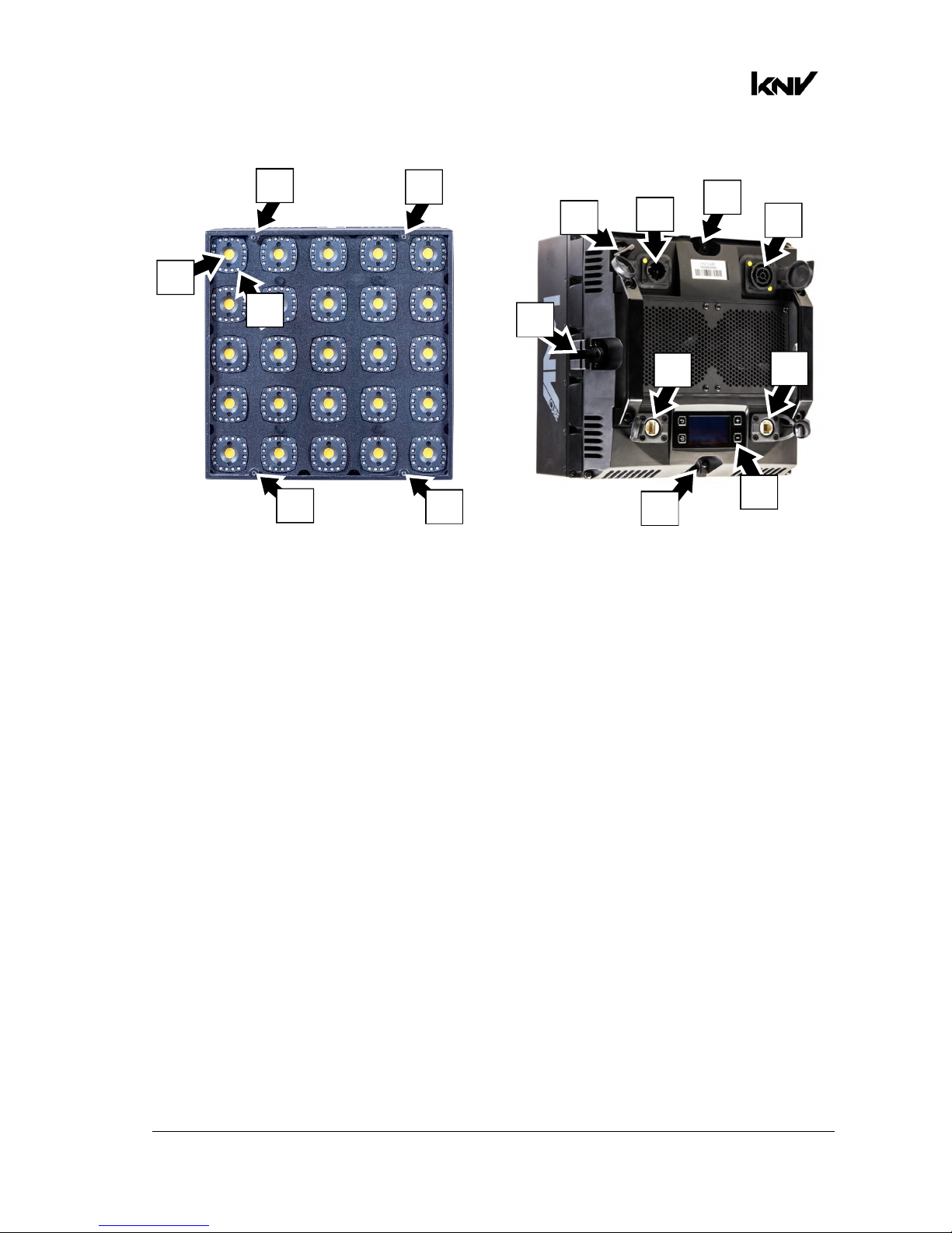
2. KNV Cube overview
Figure 1. Cube overview
A – White LED
B – RGB LEDs
C – Mounting points for optical accessories
D – Mechanical connector attachment points
E – Safety cable attachment point
F – AC mains power IN (Neutrik powerCON TRUE1)
G – AC mains power OUT / THRU (Neutrik powerCON TRUE1)
H – Neutrik EtherCON port for control data (DMX/Art-Net/sACN in/out)
I – Neutrik EtherCON port for control data (DMX/Art-Net/sACN in/out)
J – Control panel with backlit LCD display
A
B
C
C
C
C
J
D
E
F
D
G
D
H
I
Page 7
German Light Products®
KNV User Manual Rev. A 7
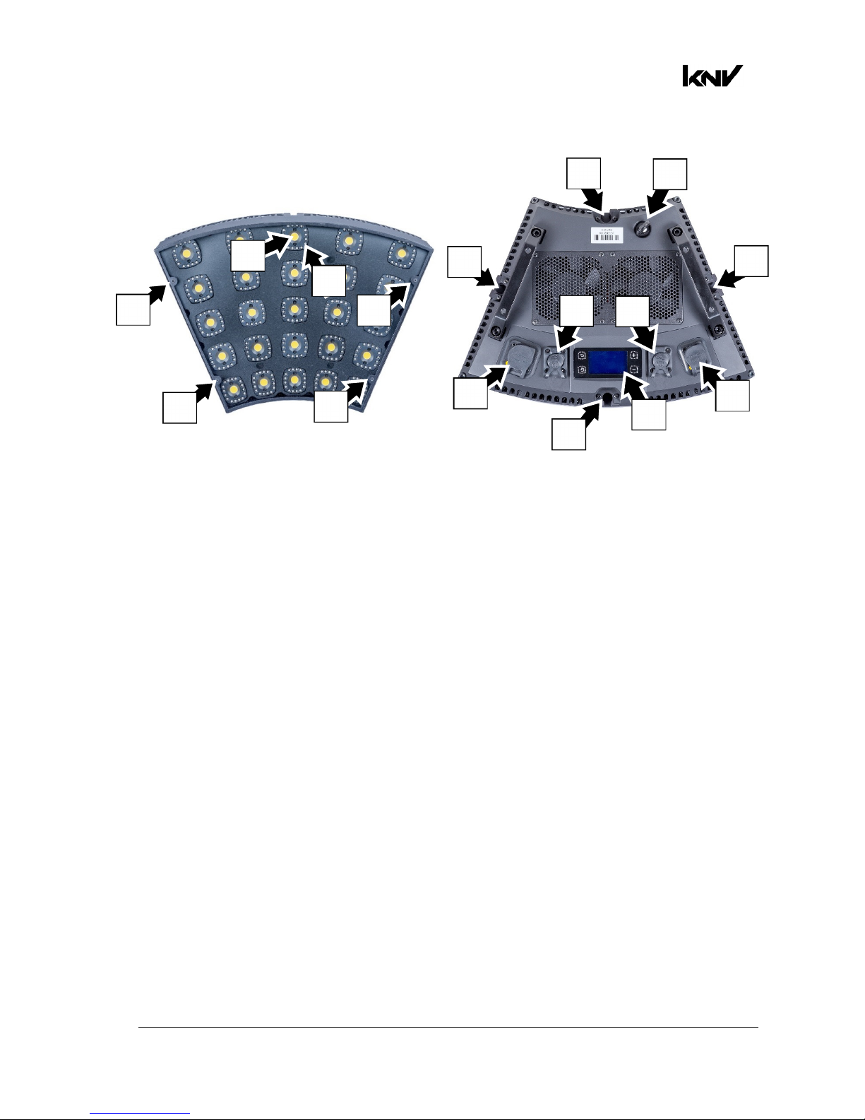
3. KNV Arc overview
Figure 2. Arc overview
A – White LED
B – RGB LEDs
C – Mounting points for optical accessories
D – Mechanical connector attachment points
E – Safety cable attachment point
F – AC mains power IN (Neutrik powerCON TRUE1)
G – AC mains power OUT / THRU (Neutrik powerCON TRUE1)
H – Neutrik EtherCON port for control data (DMX/Art-Net/sACN in/out)
I – Neutrik EtherCON port for control data (DMX/Art-Net/sACN in/out)
J – Control panel with backlit LCD display
C
C
C
C
A
B
G
F
H
I
J
D
D
D
D
E
Page 8

www.glp.de
8 KNV
User Manual Rev. A
4. Features
The KNV from GLP is a powerful strobe/color effect lighting fixture. It is available in
modular Cube and Arc variants that can be interlocked and combined to form lines
and curves, giving enormous creative possibilities.
The fixture combines powerful white light output from a 5x5 matrix of 30-watt cool
white LEDs with bright color output from a color wash panel that uses 400 high-quality
RGB LEDs in circles around the white LEDs. Total luminous flux can exceed 50 000
lumens per module.
The LED array can be pixel-mapped through any standard controller. White and color
output can be controlled separately or combined for stunning strobe, continuous
output and wash effects. Using the powerful internal multilayer FX engine, complex
dynamic effects can be created quickly with no need for a separate pixel-mapping
media server.
The KNV can be used indoors in permanent and temporary installations. Its rugged
construction and IP54 rating mean that it can also be used outdoors in temporary
installations if precautions are taken to prevent immersion in water and damage from
direct sunlight. It can be placed upright on a level surface or suspended from a
suitable structure as described in the product’s Quick Start and Installation Manual.
Four mounting points with M3 threaded holes are provided on the front of KNV fixtures
for mounting optical accessories from GLP.
Power and data can be daisy-chained and products can be interlocked for ease of
installation.
The KNV is not suitable for household use, for use in any location where unattended
children have access to it, or for use in permanent outdoor installations.
White LEDs
The KNV features a 5x5 matrix of cool white LEDs that produce powerful white light at
5000 K. The white LEDs can be controlled together or individually depending on the
DMX control mode selected.
The white LEDs offer shutter and dimming effects including a powerful strobe, flashing
at up to 16.67 Hz, or operate continuously to give high-output wash effects with a 120°
beam angle.
You can also select from a wide range of pre-programmed dynamic FX patterns to run
on the white LEDs.
Color LEDs
The KNV’s 400 RGB LEDs are arranged into circles of 16 LEDs that surround each white
LED. The RGB LEDs can be controlled together or individually depending on the DMX
control mode selected.
You can run a wide range of color effects (including strobe effects and dynamic FX
patterns) on the RGB LEDs, or you can operate them continuously using RGB color
mixing to provide a color wash with a 120° beam angle.
You can also use the RGB LEDs to add blue or red to the powerful white LEDs and
adjust their color temperature.
Page 9
German Light Products®
KNV User Manual Rev. A 9
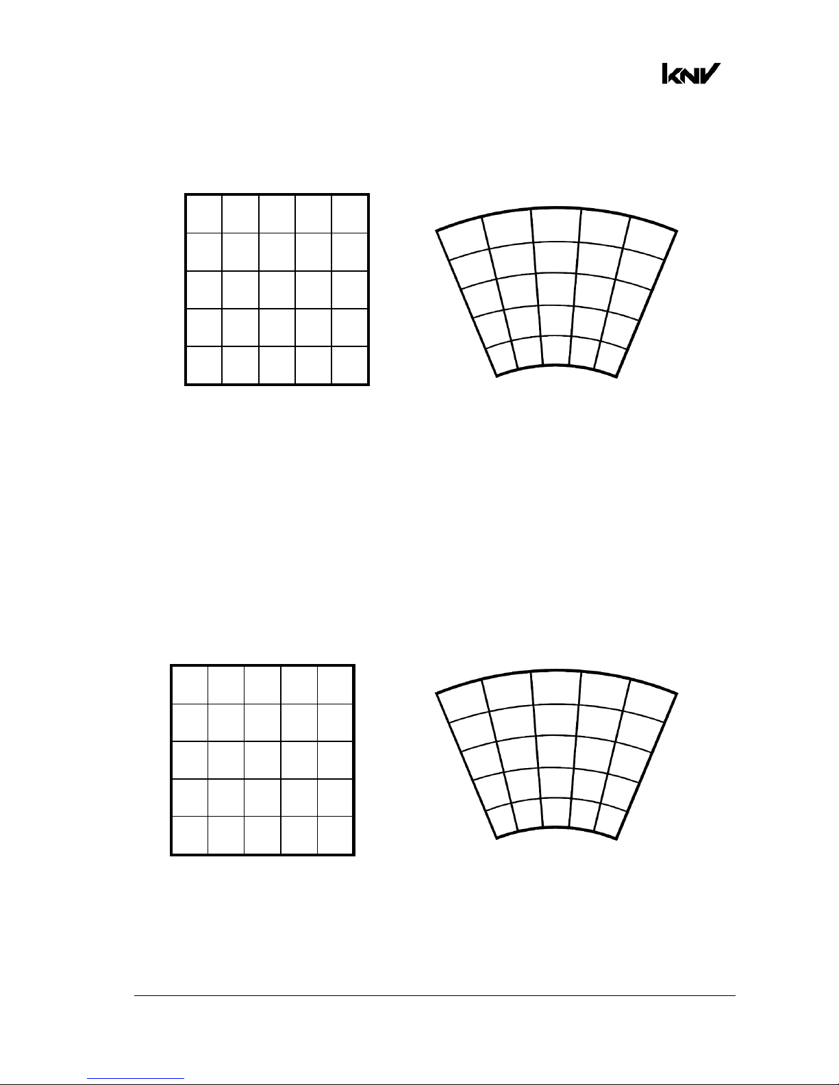
Pixel mapping
If you control the KNV’s 5 x 5 matrix of LED blocks individually, pixels are numbered as
shown below as seen from the front of the fixture:
Figure 3. Pixel layout, Cube and Arc fixtures
Pixel mirror
The Pixel mirror setting flips the numbering of the KNV’s pixels right to left. This lets you
set up symmetrical effects in multiple fixtures quickly without the need to reprogram
cues.
Figure 3 above shows the default pixel orientation when Pixel mirror is set to OFF
(Normal). Figure 4 below shows the pixel orientation when Pixel mirror is set to ON.
You can apply Pixel mirror using the Control / Settings DMX channel or in the control
panel.
Figure 4. Pixel Mirror = ON
If you want to check a fixture’s Pixel mirror status from the control desk, apply a Test
pattern (see Figure 6 on page 15) on the Control / Settings DMX channel.
1 2 3 4 5
6 7 8 9 10
11 12 13 12 15
16 17 18 19 20
21 22 23 24 25
5 4 3 2 1
10 9 8 7 6
15 14 13 12 11
20 19 18 17 16
25 24 23 22 21
1
2
3
4
5
6
11
16
21
7
12
17
22
23
24
25
18
19
20
13
14
15
10
8
9
5
4
3
2
1
10
15
20
25
9
14
19
24
23
22
21
18
17
16
13
12
11
6
8
7
Page 10
www.glp.de
10 KNV
User Manual Rev. A
Pixel orientation
In addition to the Pixel mirror setting described above, you can rotate the pixels in 90°
steps using the Control / Settings DMX channel or the fixture’s control panel.
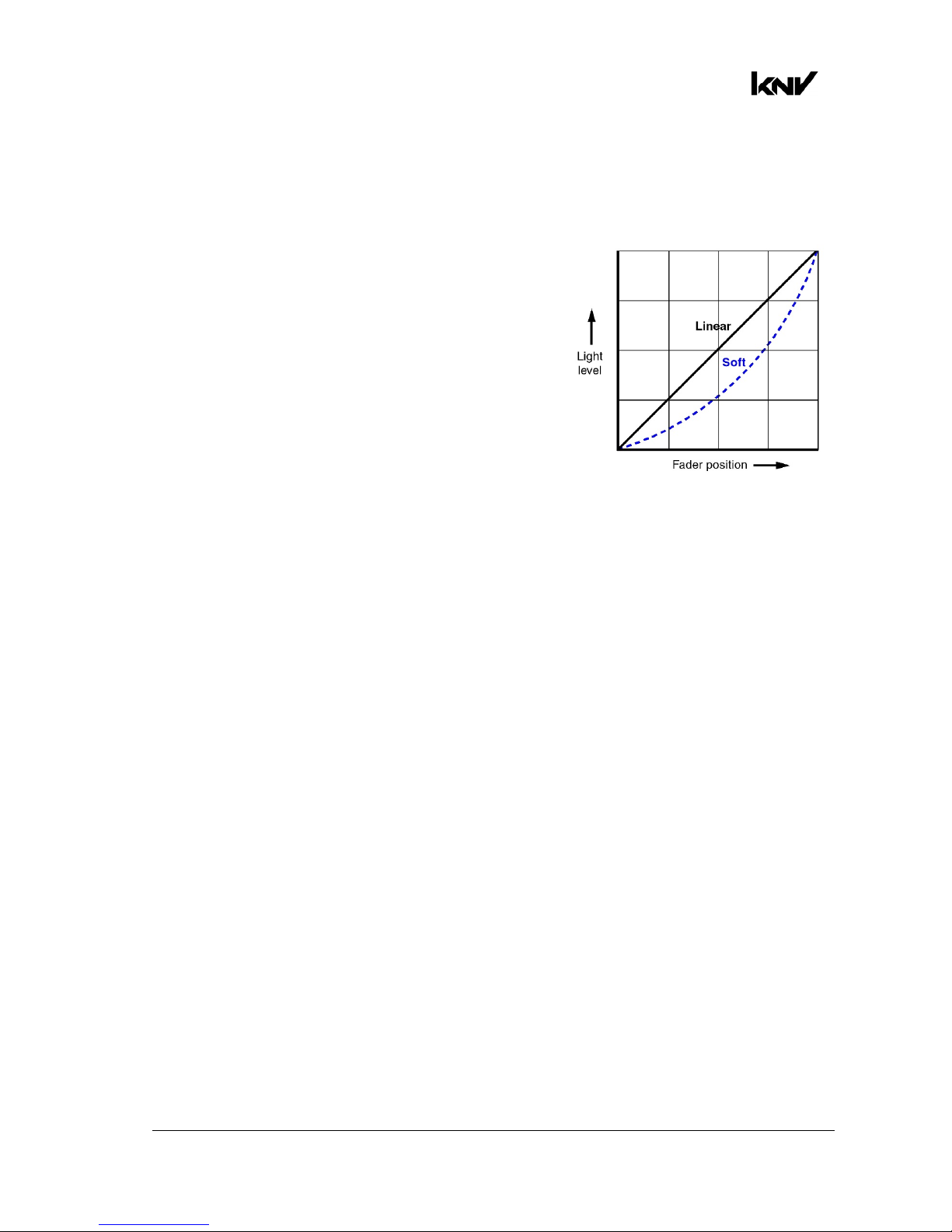
Dimming
See Figure 5. You can select from two dimming
curves using the control panel or the Control /
Settings DMX channel – Linear and Soft:
• Light output using the Linear curve will appear to
increase and decrease evenly throughout the
dimming range.
• The Soft curve gives finer control at low light
levels (where the eye is more sensitive to
changes in light level) and coarser control at
high levels.
The default setting is Soft.
Flare effect
A feature which we call the Flare effect can be applied to flashes when they are
activated on strobe channels. The Flare effect is an interference effect that you can
superimpose onto a flash. This effect is particularly impressive when combined with
increased flash length.
Random pixel sparkle
The KNV’s Flare effect channels include a Random pixel setting. This setting applies the
flare effect to individual pixels at random, giving an impressive sparkling effect. Again,
we recommend that you try combining this effect with increased flash length.
Hyperspeed
Hyperspeed is a very fast flash rate on the Shutter effects channels that gives a very
powerful effect.
FX
The KNV’s pre-programmed dynamic FX give you quick access to a wide range of
dynamic patterns and movement options.
When FX are active, you can control them using six DMX channels:
• Five dedicated channels let you select an FX, set a crossfading speed, set pattern
orientation, adjust FX length in pixels and set offsets.
• In addition to these channels, if an FX is active the third strobe channel becomes a
sixth FX control channel and lets you adjust FX speed (see details below).
Figure 5. Dimming curves
Page 11

German Light Products®
KNV User Manual Rev. A 11
Dedicated FX channels
• The first FX channel, the FX Selection channel, lets you choose and activate an FX
from a list of dynamic FX patterns.
If this channel is set to zero, the third strobe channel controls strobe flash rate. If an
FX is selected on this channel, the third strobe channel controls FX speed.
• The second FX channel, the FX Crossfading channel, sets the time it takes for the FX
to fade out. You can set FX to crossfading and apply a crossfading time from fast to
slow. You can also set FX to leave a tail behind them and apply a crossfading time
for the tail from slow to fast.
• The third FX channel, the FX Orientation channel, lets you select from a long list of
options for the orientation of the FX. Running the same FX but with different
orientation options in multiple fixtures is a fast way to set up symmetrical and/or
coordinated effects.
• The fourth FX channel, the FX Offset channel, lets you apply offsets to the FX, a
feature which lets you quickly set up synchronized FX chases in multiple fixtures.
Setting an offset determines the pixel in the pattern (not the pixel on the fixture)
where the FX pattern will start. For example, if you set the length of an FX pattern to
10 pixels and you apply an offset of 6 pixels, the fixture will blackout for the time it
takes the FX pattern to run on pixels 1 – 5, then the FX pattern will appear on the
fixture when the pattern reaches pixel 6.
• The fifth FX control channel, the FX Length channel, lets you set the total length in
pixels of the FX pattern.
FX speed control
If you select an FX on the FX Selection channel, the third strobe channel is redeployed
and becomes the FX Speed control channel. Instead of controlling strobe flash rate, it
now becomes the sixth FX control channel and lets you adjust the speed of the FX.
Setting up FX chases
If you select the same FX with the same speed in multiple fixtures, you can use the
other FX channels in combination to set up an FX chase across multiple fixtures:
• FX Crossfading / Crossfading with tail sets the rate at which one FX pattern step
fades out before the next pattern step arrives.
• FX Orientation can be used to add variety to a chase or set up multiple coordinated
chases in different groups of fixtures.
• FX Offset sets the pixel on which the FX pattern will start.
An FX pattern with no offset starts on pixel 1. You will obtain this if you set the FX
Offset channel to zero and also if you set the FX Offset channel to 001.
• FX Length sets the number of pixels over which the FX pattern will run.
The normal FX length is 5 pixels. You will obtain this 5-pixel length if you set the FX
Length channel to zero. It is not possible to set FX Length to less than 5 pixels.
When you set up FX chases, you will normally achieve the best results by increasing
FX length in steps of 5 pixels (one fixture).
Page 12

www.glp.de
12 KNV
User Manual Rev. A
To obtain synchronized chases in multiple fixtures you must set up FX Length and FX
Offset parameters in combination. Here is how FX Length and FX Offset work in a single
fixture:
• FX Length = Off (DMX value zero on the FX Length DMX channel): The FX pattern will
have the normal length of five pixels. It will start at pixel 1, run from pixel 1 to pixel 5
and then immediately start at pixel 1 again.
• FX Length = 30 (DMX value 030 on the FX Length DMX channel): The FX pattern will
start at pixel 1, run from pixel 1 to pixel 5 and then black out for the time it takes to
run the FX pattern on pixels 6 – 30.
• FX Offset = Off (DMX value zero on the FX Offset DMX channel): The FX pattern will
start at pixel 1.
• FX Offset = 6 (DMX value 006 on the FX Offset DMX channel): The FX pattern will start
at pixel 6. If you have set an FX length of 30, the pixels will black out for the time it
takes to run the FX pattern on pixels 1 – 5, then run the FX pattern on pixels 6 – 10,
then black out for the time it takes to run the FX pattern on pixels 11 – 30.
To create a single FX pattern chase that will run across an array of multiple fixtures, you
need to:
• Set FX Length in all the fixtures to the total number of pixels that the pattern will run
across, and
• Set FX Offset in each fixture in a sequence five pixels apart.
This means that, if you want an FX pattern to run across six fixtures in a horizontal row
and return immediately to pixel 1 when it reaches pixel 30 at the end of the row, you
must set FX Length to 30 on all six fixtures and set FX Offsets with a gap of five pixels
between fixtures. To give a concrete example, here is how you must set up each
fixture:
• Fixture 1: FX Length = 30, FX Offset = 1
FX will start at Pixel 1 of the 30 pixels in FX Length and run on pixels 1 - 5
• Fixture 2: FX Length = 30, FX Offset = 6
FX will start at Pixel 6 of the 30 pixels in FX Length and run on pixels 6 - 10
• Fixture 3: FX Length = 30, FX Offset = 11
FX will start at Pixel 11 of the 30 pixels in FX Length and run on pixels 11 – 15
• Fixture 4: FX Length = 30, FX Offset = 16
FX will start at Pixel 16 of the 30 pixels in FX Length and run on pixels 16 - 20
• Fixture 5: FX Length = 30, FX Offset = 21
FX will start at Pixel 21 of the 30 pixels in FX Length and run on pixels 21 - 25
• Fixture 6: FX Length = 30, FX Offset = 26
FX will start at Pixel 26 of the 30 pixels in FX Length and run on pixels 26 - 30
Page 13

German Light Products®
KNV User Manual Rev. A 13
RGB color generator
Where available, the RGB color generator effect gives instant access to automatic
color effects such as random colors, ramp up/down colors and random pixel colors.
These effects would be difficult to program on a DMX controller.
Extra shutter
In DMX modes 1, 6 and 7, an extra shutter effect is available. You can choose whether
this shutter effect should run on all LEDs (RGBW), on RGB LEDs only or on White LEDs
only. You can make this choice via DMX on the Control / Settings channel in modes 1,6
and 7 or using the fixture’s control panel.
The default setting for the extra shutter effect is RGBW.
Behavior when the fixture is not receiving a DMX signal
You can set the fixture to react in three different ways if no DMX signal is present (if the
fixture is being controlled by DMX but the DMX signal stops, or if you apply power to
the fixture when no DMX signal is present):
• Hold sets the fixture to continue obeying the last DMX values it received. This is the
default setting.
If no DMX signal was being received, the fixture will black out.
• Blackout sets the fixture to black out.
• Stand-alone sets the fixture to show the scene that has been stored using Capture
scene (see below). For safety reasons and to avoid unwanted surprises, the Standalone scene will always fade in slowly if it is activated.
To program the scene that the fixture will display if it is set to Stand-alone and no DMX
signal is present, use the Capture scene command:
• Capture scene stores the scene that the fixture is currently displaying. Once stored,
the scene is used as the fixture’s Stand-alone scene.
All these settings are available via DMX on the Control / Settings channel and in the
fixture’s control panel.
To avoid any possibility of unexpected behavior from a powerful strobe light if the DMX
signal fails, we recommend that you always set the fixture to Blackout.
Dimmer Flash mode
A shortcut to creating single flashes is available if you activate Dimmer Flash using the
Control / Settings DMX channel or the Settings menu in the fixture’s control panel.
When Dimmer Flash mode is enabled, if the Flash rate channel (the third of the Strobe
channels) is set to zero, any new DMX value that you input on the Intensity channel
(the first of the Strobe channels) will produce a single flash. In effect, all you need to do
is 'nudge the dimmer fader' to produce a flash.
If you activate this function, you can tap flashes in sync with a music beat, easily
keeping track of changes in the beat.
Page 14

www.glp.de
14 KNV
User Manual Rev. A
Display
The illuminated graphic LCD display with self-charging battery lets you change fixture
settings even when the power is off. See Chapters 5 and 6 for more details.
Using the Control / Settings DMX channel or the fixture’s control panel you can:
• Change the display orientation from Normal to Inverted for easier reading if the
fixture is flown upside-down in a rig.
• Choose between three different display modes:
- Auto: The display will automatically switch off after a few seconds if the fixture is
receiving a valid control signal and has not detected an error. If the fixture is not
receiving a valid control signal the display will flash. If the fixture has detected an
error, the display will remain constantly on and show the error.
- On: The display stays on constantly. This setting can be useful when you are
configuring or servicing the fixture.
- Off: The display will automatically switch off after a few seconds even if the fixture is
not receiving a valid control signal or if it has detected an error.
Fan modes
Four different cooling fan modes are available on the Control / Settings DMX channel
and in the fixture’s control panel. The modes let you choose cooling fan operation
options depending on how you want to allocate priority between light output and fan
noise:
• Regulated mode gives priority to light output and only operates fans as necessary. If
the fixture is blacked out, fans run at minimum speed. When light output intensity is
increased, temperature regulation increases fan speed to the level necessary to
keep the fixture at optimum temperature.
If light output is set to maximum intensity but the fans can keep the fixture at
optimum temperature, there will be no regulation of light intensity. If the fixture
begins to exceed optimum temperature, light intensity will be reduced until
optimum temperature can be maintained.
• High mode sets fans to constant high speed. This mode is optimized for maximum
light output and suits operation in high ambient temperatures and/or where fan
noise is not a critical issue. Light output intensity is smoothly reduced if it becomes
necessary in order to keep fixture temperature at optimum level.
Besides maximizing light output in high ambient temperatures, you can use high
mode to cool down a fixture quickly or to remove dust from cooling fans.
• Medium mode sets fans to constant medium speed. Light output intensity is
smoothly reduced if it becomes necessary in order to keep fixture temperature at
optimum level.
If you want to avoid any automatic reductions in output intensity that may occur in
regulated mode (see above) or if fixture temperature exceeds optimum level, we
recommend that you use medium mode in combination with one of the Output
limitation levels available via DMX and in the fixture’s control panel to keep the
fixture in output/temperature balance.
Page 15
German Light Products®
KNV User Manual Rev. A 15
• Low mode sets fans to constant low speed. This mode is optimized for minimum
noise. Light output intensity is smoothly reduced if it becomes necessary in order to
keep fixture temperature at optimum level.
If you want to avoid any automatic reductions in output intensity that may occur if
fixture temperature exceeds optimum level, we recommend that you that you use
low mode in combination with one of the Output limitation levels available via DMX
and in the fixture’s control panel to keep the fixture in output/temperature balance.
In all fan modes, if fixture temperature reaches an unsafe level, LEDs will be shut down
for a period until the fans have brought the temperature down to a safe level.
Fixture information
The Information menu in the control panel gives access to items of information from
the fixture’s sensors and memory. You can check temperature sensor readouts, see
total operating hours counters and power cycle count, and see DMX signal quality
data, for example.
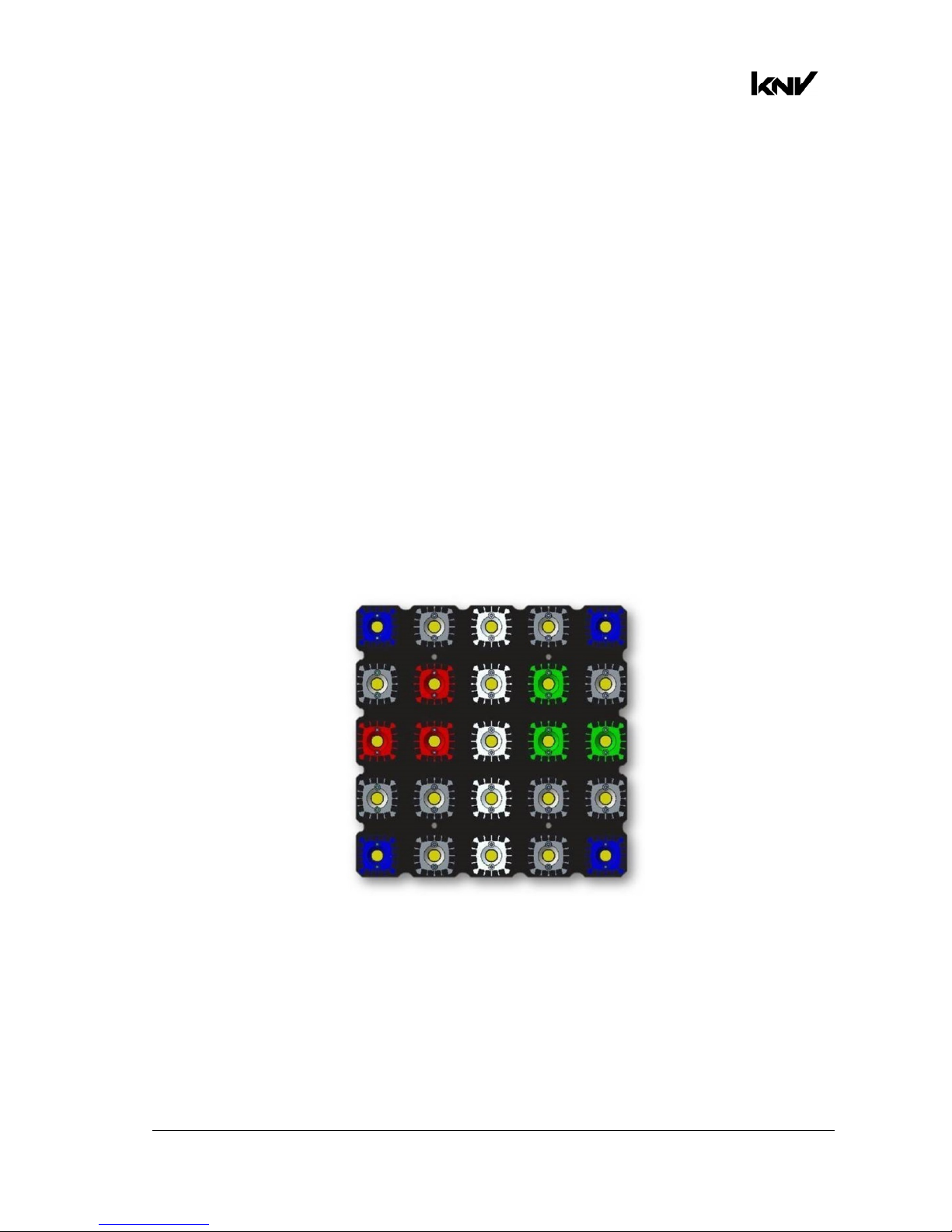
Test pattern
If you need to check a fixture’s orientation, call up the test pattern on the Control /
Settings DMX channel or in the fixture’s control panel. If the fixture is oriented normally,
the test pattern will appear as shown below:
Figure 6. Test pattern
Custom settings and factory defaults
You can customize fixture settings (DMX mode, Fan mode, Pixel orientation, etc.) via
DMX or using the fixture’s control panel. Custom settings are stored after a power
off/on cycle and after a reset.
Two options are available in the fixture’s control panel for deleting multiple custom
settings and restoring defaults:
Page 16

www.glp.de
16 KNV
User Manual Rev. A
• Load Setting Defaults reloads all the fixture’s factory default settings except DMX
address, DMX mode and Control protocol. This option returns the fixture to baseline
settings (default Fan mode, Output limitation, Pixel orientation, Dimmer curve, etc.)
without affecting its basic configuration in an installation.
• Load Factory Backup reloads all the fixture’s factory default settings including DMX
address, DMX mode and Control Protocol. This option reinitializes the fixture
completely and returns to its state when it left the factory.
Page 17
German Light Products®
KNV User Manual Rev. A 17
5.
Control menus and LCD display
Warning! DMX control is disabled when the control menus are active. Be
prepared for the fixture to emit strong light as soon as you exit the control
menus.
The control panel and LCD display provide access to user settings, readouts and
utilities.
DMX address
1
Mode 5 (1-35)
ver.14b#1
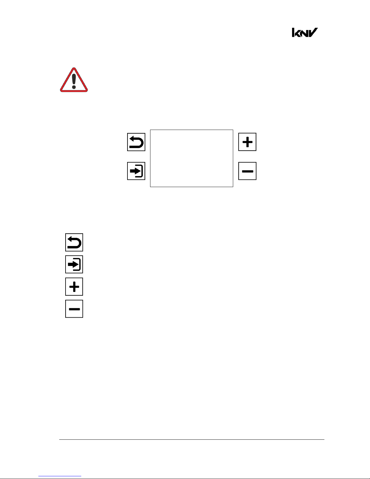
Figure 7. Main screen
The four control buttons have the following functions:
Escape: Go back one level and return to the top of the menu.
Enter: Activate the control panel if it is in sleep mode. Then enter a
menu, select a setting or implement a command.
Up: Scroll up or increase a number.
Down: Scroll down or reduce a number.
When the fixture boots up, the control panel displays fixture information including
firmware version and fixture hours before displaying the PCB reset status screen. After
resetting, the panel displays the main screen. See Figure 7. The main screen displays
the fixture’s:
• DMX address
• DMX mode and channels occupied (in Figure 7, the fixture occupies DMX channels
1-35. Channel 36 is available for the next fixture on the DMX link)
• Firmware version and build data.
DMX control is disabled when the control menus are active.
See also the Display options on the DMX Control / Settings channel and in the Display
control menu in the control panel.
Page 18

www.glp.de
18 KNV
User Manual Rev. A
6. Fixture control setup
To configure the KNV for use in a show or fixed installation, open the fixture’s control
menus and configure the fixture’s DMX Address, Control Mode (DMX Mode) and
Control Protocol (DMX, ArtNet or sACN).
If you are using ArtNet or sACN you need to set the fixture’s IP address and SubNet
Mask.
These settings will not be affected if you apply a Load Default Settings command in
the fixture’s control panel, but they will be returned to factory defaults if you apply a
Load Factory Backup command in the fixture’s control panel.
Page 19
German Light Products®
KNV User Manual Rev. A 19
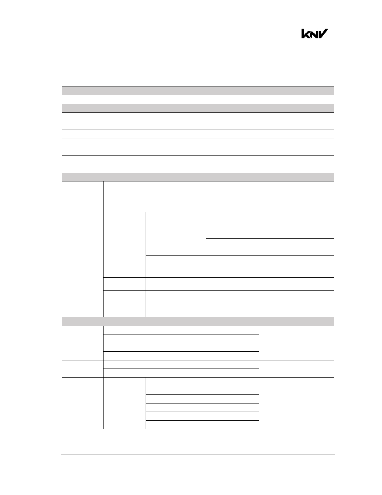
7. Control menu layout
Menus Notes
DMX Start Address
1-512 Enter DMX address
Control Mode
Mode 1 RGBW + Shutter
Mode 2 W Strobe + RGB Strobe
Mode 3 RGB Strobe + 25x W
Mode 4 W Strobe + 25x RGB
Mode 5 Multilayer
Mode 6 25x RGBW 8-bit
Mode 7 25x RGBW 16-bit
Control Protocol
Protocol Type
DMX Control via DMX protocol
ArtNet
Control via ArtNet
protocol (default)
sACN Control via sACN protocol
Ethernet
Configuration
Ethernet /
Protocol
Setup
Addressing Mode
Auto 2.X.X.X
Auto addressing in the
range 2.X.X.X
Auto 10.X.X.X
Auto addressing in the
range 10.X.X.X
Custom IP Use custom IP address
DHCP Get IP address by DHCP
Custom IP address Enter IP address Enter custom IP address
Custom Subnet
Mask
Enter Subnet
Mask
Enter custom subnet mask
ArtNet
Universe
0 - 32768 Set ArtNet universe
sACN
Universe
1 - 63999 Set sACN universe
sACN UDP
Port
2049..5568..65535 Select sACN port
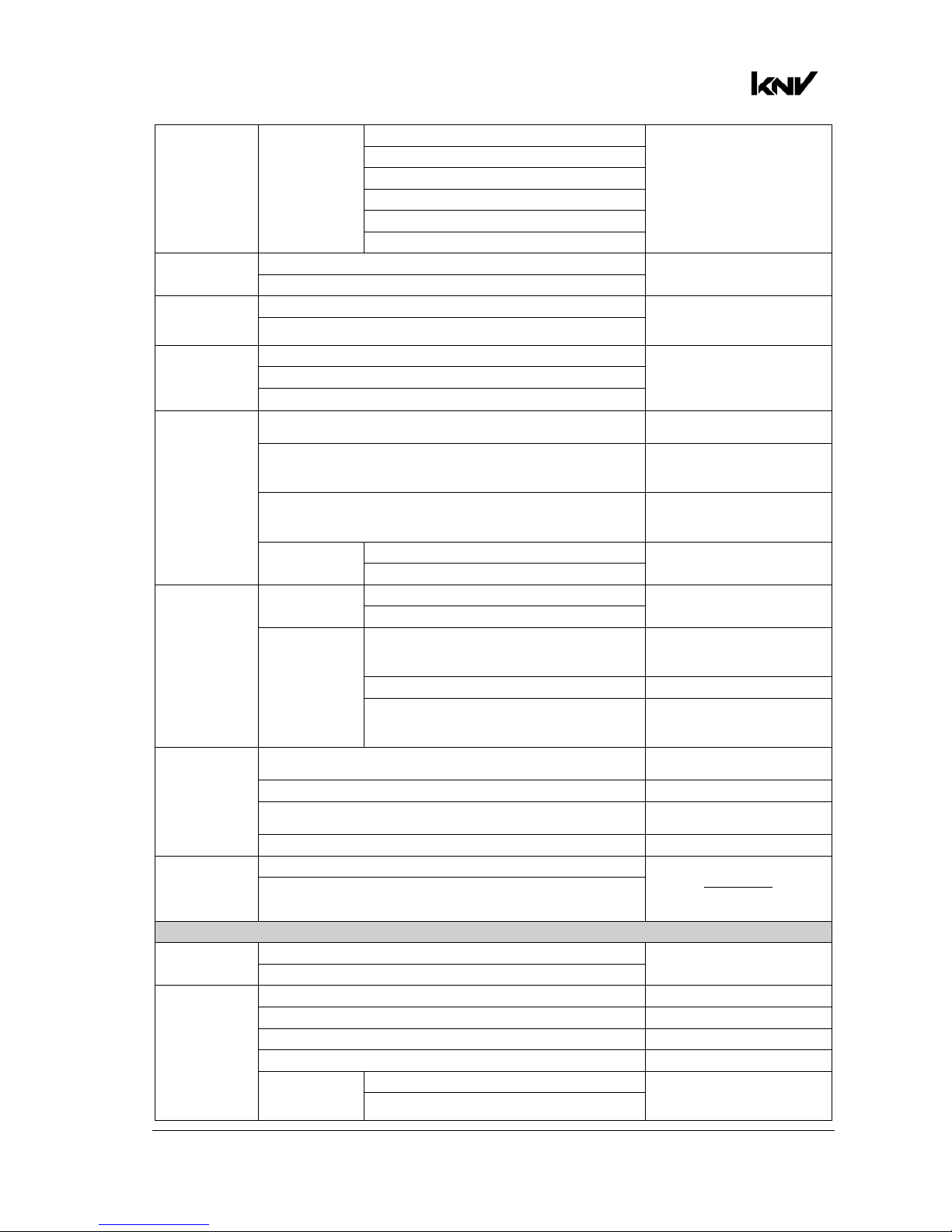
Fixture Settings
Pixel
Orientation
Normal
Set pixel orientation
Rotate 90 deg.
Rotate 180 deg.
Rotate 270 deg.
Pixel Mirrored
OFF
Set pixel flip right-to-left
ON
Output
Limitation
Output
Limitation WHITE
Off
Set maximum output for
White LEDs
80% Output
60% Output
40% Output
20% Output
10% Output
Page 20
www.glp.de
20 KNV
User Manual Rev. A
Output
Limitation
(continued)
Output
Limitation RGB
Off
Set maximum output for
RGB LEDs
80% Output
60% Output
40% Output
20% Output
10% Output
Dimmer
Curve
Soft
Select dimming curve
Linear
Dimm Flash
Off
Activate flash when
dimmer channel value is
moved
On
Extra Shutter
RGBW
Sets which LEDs are used
in the extra shutter effect
that is available in DMX
Modes 1, 6 and 7.
White
RGB
No DMX
Blackout
Fixture blacks out when no
DMX signal present
Hold
Fixture holds current scene
when no DMX signal
present
Stand Alone
Fixture goes to StandAlone scene when no
DMX signal present
Capture
Scene
No
Capture current scene for
use as Stand-Alone scene
Yes
Display
Setting
Display
Orientation
Normal
Invert display
Upside-down
Display Mode
Auto
Display sleeps unless error
detected or no valid
control signal
On Display constantly on
Off
Display off, even if error
detected or no valid
control signal
Fan Mode
Regulated
Fan speed temperatureregulated
High Fan speed constant high
Medium
Fan speed constant
medium
Low Fan speed constant low
Load Setting
Defaults
No
Load factory default
settings apart from DMX
address, DMX mode,
Control protocol
Yes
Manual Control
Reboot
No
Force fixture to reboot
Yes
Manual DMX
Red Send DMX value 0-65353
Green Send DMX value 0-65353
Blue Send DMX value 0-65353
Shutter Send DMX value 0-65353
Capture
Scene
No
Stores current control
values as Stand-Alone
scene
Yes
Page 21
German Light Products®
KNV User Manual Rev. A 21
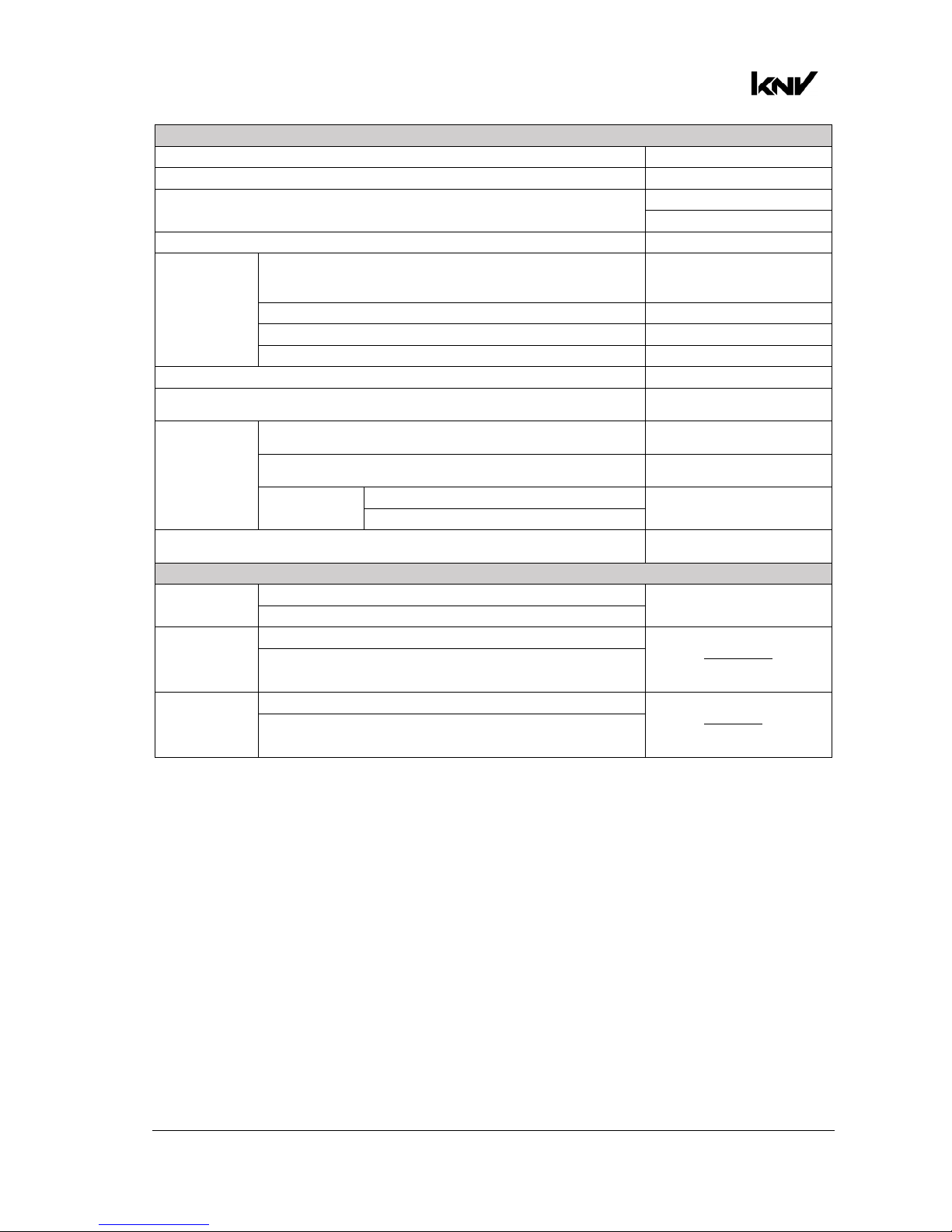
Information
Temperatures Shows temperatures
Output Limit Shows current output limit
Voltage
Shows master voltage
Shows driver voltage
DMX Link Quality
Network
TCP/IP
Shows Mode, IP Address,
Sub Address, MAC
Address (hex)
Ethernet Port Status Shows Ethernet Port Status
ArtNet Status Shows ArtNet Status
sACN Status Shows sACN Status
Serial Number Shows fixture serial number
Shape
Shows fixture type (Cube /
Arc)
Device Hours
Total (non resettable)
Shows total fixture hours
(not resettable)
Total (resettable)
Shows fixture hours since
last counter reset
Reset
Counter
No
Sets resettable fixture
hours counter to zero
Yes
Power Cycles
Shows total power cycles
(not resettable)
Service
Test Pattern
Off
Display test pattern on
fixture
On
Load Setting
Defaults
No
Load factory default
settings apart from DMX
address, DMX mode,
Control protocol
Yes
Load Factory
Backup
No
Load factory default
settings including DMX
address, DMX mode,
Control protocol
Yes
Control Menus
Default settings are written in BOLD type.
Page 22

www.glp.de
22 KNV
User Manual Rev. A
8. DMX control modes
Seven DMX control modes are available in the KNV.
In all seven DMX modes, the last DMX channel is the Control / Settings channel. This
channel lets you adjust fixture settings remotely from the DMX control desk.
• DMX Mode 1 lets you control all 25 pixels together as a group with 16-bit resolution. A
separate Shutter channel provides strobe, pixel and ramp-up/down effects. This
extra shutter affects all white and all RGB LEDs by default, but you can change this
setting via the Control/Settings DMX Channel or the fixture’s control panel so that
the shutter applies to white LEDs only or RGB LEDs only.
• DMX Mode 2 splits the KNV into a White Strobe and a separate RGB Strobe, each
with standard strobe light control channels: Intensity, Flash Rate and Flash Duration.
In addition, the Flare effect and pre-programmed dynamic FX are available for
each strobe.
• DMX Mode 3 provides an RGB strobe plus 25 individually controllable white pixels.
The RGB strobe has standard strobe control channels: Intensity, Flash Rate and Flash
Duration. It also has the Flare effect and pre-programmed dynamic FX. The 25
individual white pixels have a separate Shutter channel with strobe, pixel and rampup/down effects.
• DMX Mode 4 provides a White Strobe plus 25 individually controllable RGB pixels.
The White strobe has standard strobe control channels: Intensity, Flash Rate and
Flash Duration. It also has the Flare effect and pre-programmed dynamic FX. The 25
individual RGB pixels have a separate Shutter channel with strobe, pixel and rampup/down effects.
• DMX Mode 5 provides three different layers:
- The Base Layer has lowest priority (other layers override it), so it acts as a
background layer. The Base layer has RGBW intensity control.
- Layer 2 has priority over the base layer, so it acts as a middle layer.
- Layer 3 has highest priority, so it acts as a top layer.
- Layers 2 and 3 both have standard RGBW strobe control channels plus the Flare
effect and pre-programmed dynamic FX. Layers 2 and 3 also have a 16-bit Layer
Master Channel that controls the transparency of the layer.
FX layer priorities work in true color, which means that colors are not mixed. If you
run a red snake FX on Layer 2 over the top of a red background on the Base Layer,
the snake will be blue, not a mix of blue and red.
Applying transparency to a layer allows the color of the background layer or the
lower priority layer to shine through.
If you want to dim a layer’s colors without color from lower priority layers shining
through, reduce the intensity of the colors without applying transparency to the
layer. If you reduce the intensity of all the colors to zero, you can run a black effect
over the top of lower priority layers.
• In DMX Modes 2, 3, 4 and 5 if no FX is selected (FX Selection channel is set to zero),
the Flash rate channel controls the flash rate of the Strobe. If an FX is selected, the
Flash rate channel is redeployed and controls the speed of the effect instead.
Page 23

German Light Products®
KNV User Manual Rev. A 23
• DMX Modes 6 and 7 give you individual control of 25 separate pixels with 8- or 16-bit
resolution. A separate Shutter channel provides strobe, pixel and ramp-up/down
effects. This extra shutter affects all the LEDs, both white and RGB, by default, but
you can change this setting via the Control / Settings DMX Channel or the fixture’s
control panel so that the shutter applies to white LEDs only or to RGB LEDs only.
Special notes on the DMX tables
In the following DMX channel layout tables:
• Default settings are indicated with bold type.
• Where commands are marked with an asterisk * you must send that value
continuously for 3 seconds (or other duration if indicated in the table) to apply the
command.
• Where LED orientation commands are marked with two asterisks ** the direction of
FX pattern movement is reversed compared to the similar commands available
earlier on the same channel. The orientation of the pattern itself is unchanged.
Page 24
www.glp.de
24 KNV
User Manual Rev. A
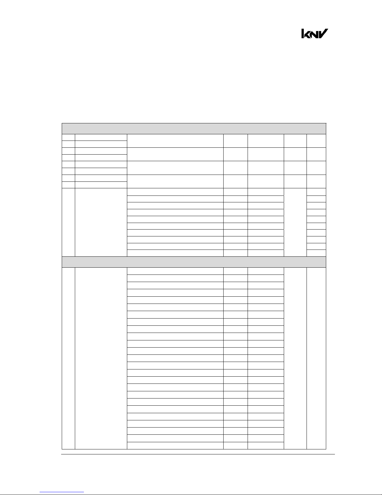
Control channel layout
DMX Mode 1: RGBW 16-bit
10 DMX Channels
Channel Command
DMX
range Percent
Default
DMX Fade
RGBW
1 Red coarse
All pixels, intensity 0-100% 0-65535 0-100% 0 Fade
2 Red fine
3 Green coarse
All pixels, intensity 0-100% 0-65535 0-100% 0 Fade
4 Green fine
5 Blue coarse
All pixels, intensity 0-100% 0-65535 0-100% 0 Fade
6 Blue fine
7 White coarse
All pixels, intensity 0-100% 0-65535 0-100% 0 Fade
8 White fine
9 Shutter
Shutter closed 0-4 0-1.6%
255
Snap
Sync ramp up slow > fast 5-39 2.0-15.3% Fade
Sync ramp down slow > fast 40-74 15.7-29.0% Fade
Sync ramp up-down slow > fast 75-109 29.4-%42.7 Fade
Sync double flash slow >fast 110-144 43.1-56.5% Fade
Random pixel slow > fast 145-179 56.9-70.2% Fade
Random strobe slow > fast 180-214 70.6-83.9% Fade
Sync strobe 0.289 > 16.67 Hz 215-249 84.3-97.6% Fade
Hyperspeed 250-252 98.0-98.8% Snap
Open 253-255 99.2-100% Snap
Control / Settings
10 Control / Settings
Idle 0-11 0-4.3% 0 Snap
No function 12-38 4.7-14.9%
Dimmer flash Off* 39-41 15.3-16.1%
Dimmer flash On* 42-44 16.5-17.3%
No function 45-47 17.6-18.4%
Dimming curve Soft* 48-50 18.8-19.6%
Dimming curve Linear* 51-53 20.0-20.8%
No function 54-56 21.2-22.0%
Extra Shutter RGBW* 57-59 22.4-23.1%
Extra Shutter RGB only* 60-62 23.5-24.3%
Extra Shutter White only* 63-65 24.7-25.5%
No function 66-68 25.9-26.7%
Fan mode regulated* 69-71 27.1-27.8%
Fan mode high* 72-74 28.2-29.0%
Fan mode medium* 75-77 29.4-30.2%
Fan mode low* 78-80 30.6-31.4%
No function 81-83 31.8-32.5%
Display On* 84-86 32.9-33.7%
Display Off* 87-89 34.1-34.9%
Display Auto* 90-92 35.3-36.1%
Display invert Off* 93-95 36.5-37.3%
Display invert On* 96-98 37.6-38.4%
No DMX = Capture scene* 99-101 38.8-39.6%
No DMX = Stand-alone* 102-104 40.0-40.8%
No DMX = Blackout* 105-107 41.2-42.0%
Page 25
German Light Products®
KNV User Manual Rev. A 25
No DMX = Hold* 108-110 42.4-43.1%
Test pattern On* 111-113 43.5-44.3%
Test pattern Off* 114-116 44.7-45.5%
Rotation Off* 117-119 45.9-46.7%
Rotate 90° * 120-122 47.1-47.8%
Rotate 180° * 123-125 48.2-49.0%
Rotate 270° * 126-128 49.4-50.2%
Pixel mirror Off* 129-131 50.6-51.4%
Pixel mirror On* 132-134 51.8-52.5%
White output limitation Off* 135-137 52.9-53.7%
White output limitation 80%* 138-140 54.1-54.9%
White output limitation 60%* 141-143 55.3-56.1%
White output limitation 40%* 144-146 56.5-57.3%
White output limitation 20%* 147-149 57.6-58.4%
White output limitation 10%* 150-152 55.8-59.6%
No function 153-158 60.0-62.0%
RGB output limitation Off%* 159-161 62.4-63.1%
RGB output limitation 80%* 162-164 63.5-64.3%
RGB output limitation 60%* 165-167 64.7-65.5%
RGB output limitation 40%* 168-170 65.9-66.7%
RGB output limitation 20%* 171-173 67.1-67.8%
RGB output limitation 10%* 174-176 68.2-69.0%
No function 177-251 69.4-98.4%
Reboot fixture* 252-255 98.8-100%
Page 26
www.glp.de
26 KNV
User Manual Rev. A
DMX Mode 2: White strobe with FX, RGB with FX
23 DMX Channels
Channel Command
DMX
range Percent
Default
DMX Fade
Channel group A: White strobe with FX
1
White LEDs
intensity
Intensity 0-100% 0-255 0-100% 0 Fade
2
White LEDs flash
duration
Flash duration 7-650 ms 0-255 0-100% 0 Fade
3
White LEDs flash
rate (if FX are not
active)
No flash
Single flash if Dimmer Flash = ON
and value is changed on Ch 1
0-1 0-0.4% 0 Snap
Flash rate 0.289-16.67 Hz 2-250 0.8-98% Fade
Hyperspeed 251-252 98.4-98.8% Snap
Continuously on 253-255 99.2-100% Snap
FX speed (if FX
are active)
FX speed = stop 0-1 0-0.4% Snap
FX speed = slow > fast 2-253 0.8-98.8% Fade
FX speed = stop 254-255 99.2-100% Snap
4
White LEDs Flare
effect
Off 0-9 0-3.5% 0 Snap
Slow > fast 10-49 3.9-19.2% Fade
Off 50-59 19.6-23.1% Snap
Random slow > fast 60-109 23.5-42.7% Fade
Off 110-119 43.1-46.7% Snap
Random pixel slow > fast 120-169 47.1-66.3% Fade
Off 170-255 66.7-100% Snap
5
White LEDs FX
selection
FX Off 0-2 0-0.8% 0 Snap
Sync strobe - circle mask 3-5 1.2-2.0%
Sync strobe - 4 dot mask 6-8 2.4-3.1%
Sync strobe - 1 dot mask 9-11 3.5-4.3%
Random strobe - all 12-14 4.7-5.5%
Random strobe - circle mask 15-17 5.9-6.7%
Random strobe - 4 dot mask 18-20 7.1-7.8%
Random strobe - 1 dot mask 21-23 8.2-9.0%
Lite in/out - all 24-26 9.4-10.2%
Lite in/out - circle mask 27-29 10.6-11.4%
Lite in/out - 4 dot mask 30-32 11.8-12.6%
Lite in/out - 1 dot mask 33-35 12.9-13.7%
Snake 36-38 14.1-14.9%
Raindrops 39-41 15.3-16.1%
Random pixel 42-44 16.5-17.3%
Random fake x 2 45-47 17.6-18.4%
Random fake x 4 48-50 18.8-19.6%
Line 51-53 20.0-20.8%
Double line 54-56 21.2-22.0%
Corner to corner line 57-59 22.4-23.1%
Tilted double lines 60-62 23.5-24.3%
Tilted double lines in to out 63-65 24.7-25.5%
Center line running dot 66-68 25.9-26.7%
Middle line running dot 69-71 27.1-27.8%
Outer line running dot 72-74 28.2-29.0%
Corner to corner 75-77 29.4-30.2%
Arrow 78-80 30.6-31.4%
Wave 81-83 31.8-32.5%
Wheel 84-86 32.9-33.7%
Page 27
German Light Products®
KNV User Manual Rev. A 27
Half wheel 87-89 34.1-34.9%
Circling dot 90-92 35.3-36.1%
Outer circle 93-95 36.5-37.3%
Inner circle 96-98 37.6-38.4%
Outer 4 dots 99-101 38.8-39.6%
Outer single dot 102-104 40.0-40.8%
Middle single dot 105-107 41.2-42.0%
Spinning 2x1 dots 108-110 42.4-43.1%
Asymmetrical 4 dots 111-113 43.5-44.3%
Symmetrical 4 dots 114-116 44.7-45.5%
Square 117-119 45.9-46.7%
Inside out 120-122 47.1-48.8%
Inside out 2 123-125 48.2-49.0%
Abstract 1 126-128 49.4-50.2%
Abstract 2 129-131 50.6-51.4%
Abstract 3 132-134 51.8-52.5%
Hash tag 135-137 52.9-53.7%
Flip flop 138-140 54.1-54.9%
Jumping slash 141-143 55.3-56.1%
Jumping 'L' 144-146 56.5-57.3%
Jumping pins 147-149 57.6-58.4%
Off - No Strobe or Fx 150-255 58.8-100%
6
White LEDs FX
crossfade time
Off 0-1 0-0.4% 0 Snap
Crossfade fast > slow 2-127 0.8-49.8% Fade
Crossfade and tail slow > fast 128-255 50.2-100% Fade
7
White LEDs
orientation
Off 0-4 0-1.6% 0 Snap
Rotate 90° 5-9 2.0-3.5%
Rotate 180° 10-14 3.9-5.5%
Rotate 270° 15-19 5.9-7.5%
Horizontal flip 20-24 7.8-9.4%
Rotate 90° & vertical flip 25-29 9.8-11.4%
Rotate 180° & horizontal flip 30-34 11.8-13.3%
Rotate 270° & vertical flip 35-39 13.7-15.3%
Off 40-44 15.7-17.3%
Random rotate & flip 45-49 17.7-19.2%
Random position 50-54 19.6-21.2%
Fix 90° rotation & random position 55-59 21.6-23.1%
Fix 180° rotation & random position 60-64 23.5-25.1%
Fix 270° rotation & random position 65-69 25.5-27.1%
Off 70-74 27.5-29.0%
Bounce 75-79 29.4-31.0%
Bounce & rotate 90° 80-84 31.4-32.9%
Bounce & rotate 180° 85-89 33.3-34.9%
Bounce & rotate 270° 90-94 35.3-36.9%
Off 95-99 37.3-38.8%
Rotate CCW at end 100-104 39.2-40.8%
Rotate CW at end 105-109 41.2-42.7%
Random rotate at end 110-114 43.1-44.7%
Off 115-134 45.1-52.5%
Rotate 90° ** 135-139 52.9-54.5%
Rotate 180° ** 140-144 54.9-56.5%
Rotate 270° ** 145-149 56.9-58.4%
Horizontal flip ** 150-154 58.8-60.4%
Rotate 90° & vertical flip ** 155-159 60.8-62.4%
Rotate 180° & horizontal flip ** 160-164 62.7-64.3%
Page 28
www.glp.de
28 KNV
User Manual Rev. A
Rotate 270° & vertical flip ** 165-169 64.7-66.3%
Off 170-174 66.7-68.2%
Random Rotate & flip ** 175-179 68.6-70.2%
Random position ** 180-184 70.6-72.2%
Fix 90° rotation & random
position ** 185-189 72.5-74.1%
Fix 180° rotation & random
position ** 190-194 74.5-76.1%
Fix 270° rotation & random
position ** 195-199 76.5-78.0%
Off 200-204 78.4-80.0%
Bounce ** 205-209 80.4-82.0%
Bounce & rotate 90° ** 210-214 82.4-83.9%
Bounce & rotate 180° ** 215-219 84.3-85.9%
Bounce & rotate 270° ** 220-224 86.3-87.8%
Off 225-229 88.2-89.8%
Rotate CCW at end ** 230-234 90.2-91.8%
Rotate CW at end ** 235-239 92.2-93.7%
Random rotate at end ** 240-244 94.1-95.7%
Off 245-255 96.1-100%
8 White LEDs FX
offset
0-100% 0-255 0-100% 0 Fade
9 White LEDs FX
length
0-100% 0-255 0-100% 0 Fade
Channel group B: RGB strobe with FX
10 RGB LEDs dimmer Intensity 0-100% 0-255 0-100% 0 Fade
11
RGB LEDs flash
duration
Flash duration 7-650 ms 0-255 0-100% 0 Fade
12
RGB LEDs flash
rate (if FX are not
active)
No flash 0-1 0-0.4% 0 Snap
Flash rate 0.289-16.67 Hz 2-250 0.8-98% Fade
Hyperspeed 251-254 98.4-99.6% Snap
Continuously on 255 100% Snap
FX speed (if FX
are active)
FX speed = stop 0-1 0-0.4% Snap
FX speed = slow > fast 2-253 0.8-98.8% Fade
FX speed = stop 254-255 99.2-100% Snap
13 Red Red intensity 0-100% 0-255 0-100% 255 Fade
14 Green Green intensity 0-100% 0-255 0-100% 255 Fade
15 Blue Blue intensity 0-100% 0-255 0-100% 255 Fade
16
RGB LEDs Flare
effect
Off 0-9 0-3.5% 0 Snap
Slow > fast 10-49 3.9-19.2% Fade
Off 50-59 19.6-23.1% Snap
Random slow > fast 60-109 23.5-42.7% Fade
Off 110-119 43.1-46.7% Snap
Random pixel slow > fast 120-169 47.1-66.3% Fade
Off 170-255 66.7-100% Snap
17
RGB LEDs FX
selection
FX Off 0-2 0-0.8% 0 Snap
Sync strobe - circle mask 3-5 1.2-2.0%
Sync strobe - 4 dot mask 6-8 2.4-3.1%
Sync strobe - 1 dot mask 9-11 3.5-4.3%
Random strobe - all 12-14 4.7-5.5%
Random strobe - circle mask 15-17 5.9-6.7%
Random strobe - 4 dot mask 18-20 7.1-7.8%
Random strobe - 1 dot mask 21-23 8.2-9.0%
Lite in/out - all 24-26 9.4-10.2%
Lite in/out - circle mask 27-29 10.6-11.4%
Lite in/out - 4 dot mask 30-32 11.8-12.6%
Page 29
German Light Products®
KNV User Manual Rev. A 29
Lite in/out - 1 dot mask 33-35 12.9-13.7%
Snake 36-38 14.1-14.9%
Raindrops 39-41 15.3-16.1%
Random pixel 42-44 16.5-17.3%
Random fake x 2 45-47 17.6-18.4%
Random fake x 4 48-50 18.8-19.6%
Line 51-53 20.0-20.8%
Double line 54-56 21.2-22.0%
Corner to corner line 57-59 22.4-23.1%
Tilted double lines 60-62 23.5-24.3%
Tilted double lines in to out 63-65 24.7-25.5%
Center line running dot 66-68 25.9-26.7%
Middle line running dot 69-71 27.1-27.8%
Outer line running dot 72-74 28.2-29.0%
Corner to corner 75-77 29.4-30.2%
Arrow 78-80 30.6-31.4%
Wave 81-83 31.8-32.5%
Wheel 84-86 32.9-33.7%
Half wheel 87-89 34.1-34.9%
Circling dot 90-92 35.3-36.1%
Outer circle 93-95 36.5-37.3%
Inner circle 96-98 37.6-38.4%
Outer 4 dots 99-101 38.8-39.6%
Outer single dot 102-104 40.0-40.8%
Middle single dot 105-107 41.2-42.0%
Spinning 2x1 dots 108-110 42.4-43.1%
Asymmetrical 4 dots 111-113 43.5-44.3%
Symmetrical 4 dots 114-116 44.7-45.5%
Square 117-119 45.9-46.7%
Inside out 120-122 47.1-48.8%
Inside out 2 123-125 48.2-49.0%
Abstract 1 126-128 49.4-50.2%
Abstract 2 129-131 50.6-51.4%
Abstract 3 132-134 51.8-52.5%
Hash tag 135-137 52.9-53.7%
Flip flop 138-140 54.1-54.9%
Jumping slash 141-143 55.3-56.1%
Jumping 'L' 144-146 56.5-57.3%
Jumping pins 147-149 57.6-58.4%
Off - No Strobe or FX 150-255 58.8-100%
18
RGB LEDs FX
crossfade time
Off 0-1 0-0.4% 0 Snap
Crossfade fast > slow 2-127 0.8-49.8% Fade
Crossfade and tail slow > fast 128-255 50.2-100% Fade
19
RGB LEDs
orientation
Off 0-4 0-1.6% 0 Snap
Rotate 90° 5-9 2.0-3.5%
Rotate 180° 10-14 3.9-5.5%
Rotate 270° 15-19 5.9-7.5%
Horizontal flip 20-24 7.8-9.4%
Rotate 90° & vertical flip 25-29 9.8-11.4%
Rotate 180° & horizontal flip 30-34 11.8-13.3%
Rotate 270° & vertical flip 35-39 13.7-15.3%
Off 40-44 15.7-17.3%
Random rotate & flip 45-49 17.7-19.2%
Random position 50-54 19.6-21.2%
Fix 90° rotation & random position 55-59 21.6-23.1%
Page 30
www.glp.de
30 KNV
User Manual Rev. A
Fix 180° rotation & random position 60-64 23.5-25.1%
Fix 270° rotation & random position 65-69 25.5-27.1%
Off 70-74 27.5-29.0%
Bounce 75-79 29.4-31.0%
Bounce & rotate 90° 80-84 31.4-32.9%
Bounce & rotate 180° 85-89 33.3-34.9%
Bounce & rotate 270° 90-94 35.3-36.9%
Off 95-99 37.3-38.8%
Rotate CCW at end 100-104 39.2-40.8%
Rotate CW at end 105-109 41.2-42.7%
Random rotate at end 110-114 43.1-44.7%
Off 115-134 45.1-52.5%
Rotate 90° ** 135-139 52.9-54.5%
Rotate 180° ** 140-144 54.9-56.5%
Rotate 270° ** 145-149 56.9-58.4%
Horizontal flip ** 150-154 58.8-60.4%
Rotate 90° & vertical flip ** 155-159 60.8-62.4%
Rotate 180° & horizontal flip ** 160-164 62.7-64.3%
Rotate 270° & vertical flip ** 165-169 64.7-66.3%
Off 170-174 66.7-68.2%
Random Rotate & flip ** 175-179 68.6-70.2%
Random position ** 180-184 70.6-72.2%
Fix 90° rotation & random posn. ** 185-189 72.5-74.1%
Fix 180° rotation & random posn. ** 190-194 74.5-76.1%
Fix 270° rotation & random posn. ** 195-199 76.5-78.0%
Off 200-204 78.4-80.0%
Bounce ** 205-209 80.4-82.0%
Bounce & rotate 90° ** 210-214 82.4-83.9%
Bounce & rotate 180° ** 215-219 84.3-85.9%
Bounce & rotate 270° ** 220-224 86.3-87.8%
Off 225-229 88.2-89.8%
Rotate CCW at end ** 230-234 90.2-91.8%
Rotate CW at end ** 235-239 92.2-93.7%
Random rotate at end ** 240-244 94.1-95.7%
Off 245-255 96.1-100%
20 RGB LEDs FX offset 0-100% 0-255 0-100% 0 Fade
21 RGB LEDs FX
length
0-100% 0-255 0-100% 0 Fade
22
RGB LEDs color
generator
Off 0-9 0-3.5% 0 Snap
Random all pixels RGBCMY 10-19 3.9-7.5% Snap
Random single pixel RGBCMY 20-29 7.8-11.4% Snap
Random all pixels bright colors 30-39 11.8-15.3% Snap
Random single pixel bright colors 40-49 15.7-19.2% Snap
Red / Blue 50-59 19.6-23.1% Snap
Red / Green 60-69 23.5-27.1% Snap
Blue / Green 70-79 27.5-31.0% Snap
Yellow / Magenta 80-89 31.4-34.9% Snap
Yellow / Cyan 90-99 35.3-38.8% Snap
Cyan / Magenta 100-109 39.2-42.7% Snap
Yellow / Blue 110-119 43.1-46.7% Snap
Green / Magenta 120-129 47.1-50.6% Snap
Red / Green / Blue 130-139 51.0-54.5% Snap
Red / Yellow / Blue 140-149 54.9-58.4% Snap
Red / Green / Blue / Yellow /
Magenta / Cyan 150-159
58.8%-62.4%
Snap
Page 31

German Light Products®
KNV User Manual Rev. A 31
Red / Green / Blue - Horizontal line 160-169 62.7-66.3% Snap
Red / Green / Blue - Vertical line 170-179 66.7-70.2% Snap
No function 180-219 70.6-85.9% Snap
Color scroll, slow -> fast 220-229 86.3-89.8% Fade
Lite in 230-239 90.2-93.7% Snap
Lite out 240-249 94.1-97.6% Snap
Off 250-255 98.0-100% Snap
Control / Settings
23 Control / Settings
Idle 0-11 0-4.3% 0 Snap
No function 12-38 4.7-14.9%
Dimmer flash Off* 39-41 15.3-16.1%
Dimmer flash On* 42-44 16.5-17.3%
No function 45-47 17.6-18.4%
Dimming curve Soft* 48-50 18.8-19.6%
Dimming curve Linear* 51-53 20.0-20.8%
No function 54-68 21.2-26.7%
Fan mode regulated* 69-71 27.1-27.8%
Fan mode high* 72-74 28.2-29.0%
Fan mode medium* 75-77 29.4-30.2%
Fan mode low* 78-80 30.6-31.4%
No function 81-83 31.8-32.5%
Display On* 84-86 32.9-33.7%
Display Off* 87-89 34.1-34.9%
Display Auto* 90-92 35.3-36.1%
Display invert Off* 93-95 36.5-37.3%
Display invert On* 96-98 37.6-38.4%
No DMX = Capture scene* 99-101 38.8-39.6%
No DMX = Stand-alone* 102-104 40.0-40.8%
No DMX = Blackout* 105-107 41.2-42.0%
No DMX = Hold* 108-110 42.4-43.1%
Test pattern On* 111-113 43.5-44.3%
Test pattern Off* 114-116 44.7-45.5%
Rotation Off* 117-119 45.9-46.7%
Rotate 90° * 120-122 47.1-47.8%
Rotate 180° * 123-125 48.2-49.0%
Rotate 270° * 126-128 49.4-50.2%
Pixel mirror Off* 129-131 50.6-51.4%
Pixel mirror On* 132-134 51.8-52.5%
White output limitation Off* 135-137 52.9-53.7%
White output limitation 80%* 138-140 54.1-54.9%
White output limitation 60%* 141-143 55.3-56.1%
White output limitation 40%* 144-146 56.5-57.3%
White output limitation 20%* 147-149 57.6-58.4%
White output limitation 10%* 150-152 55.8-59.6%
No function 153-158 60.0-62.0%
RGB output limitation Off* 159-161 62.4-63.1%
RGB output limitation 80%* 162-164 63.5-64.3%
RGB output limitation 60%* 165-167 64.7-65.5%
RGB output limitation 40%* 168-170 65.9-66.7%
RGB output limitation 20%* 171-173 67.1-67.8%
RGB output limitation 10%* 174-176 68.2-69.0%
No function 177-251 69.4-98.4%
Reboot fixture* 252-255 98.8-100%
Page 32

www.glp.de
32 KNV
User Manual Rev. A
DMX Mode 3: RGB strobe with FX, White 25-pixel
40 DMX Channels
Channel Command
DMX
range Percent
Default
DMX Fade
Channel group A: RGB strobe with FX
1 RGB LEDs dimmer Intensity 0-100% 0-255 0-100% 0 Fade
2
RGB LEDs flash
duration
Flash duration 7-650 ms 0-255 0-100% 255 Fade
3
RGB LEDs flash rate
(if FX not active)
No flash
Single flash if Dimmer Flash = ON
and value is changed on Ch 1
0-1 0-0.4%
0 Snap
Flash rate 0.289-16.67 Hz 2-250 0.8-98% Fade
Hyperspeed 251-254 98.4-99.6% Snap
Continuously on 255 100% Snap
RGB LEDs FX speed
(if FX active)
FX speed = stop 0-1 0-0.4% Snap
FX speed = slow > fast 2-253 0.8-98.8% Fade
FX speed = stop 254-255 99.2-100% Snap
4 Red Red intensity 0-100% 0-255 0-100% 255 Fade
5 Green Green intensity 0-100% 0-255 0-100% 255 Fade
6 Blue Blue intensity 0-100% 0-255 0-100% 255 Fade
7
RGB LEDs Flare
effect
Off 0-9 0-3.5% 0 Snap
Slow > fast 10-49 3.9-19.2% Fade
Off 50-59 19.6-23.1% Snap
Random slow > fast 60-109 23.5-42.7% Fade
Off 110-119 43.1-46.7% Snap
Random pixel slow > fast 120-169 47.1-66.3% Fade
Off 170-255 66.7-100% Snap
8
RGB LEDs FX
selection
FX Off 0-2 0-0.8% 0 Snap
Sync strobe - circle mask 3-5 1.2-2.0%
Sync strobe - 4 dot mask 6-8 2.4-3.1%
Sync strobe - 1 dot mask 9-11 3.5-4.3%
Random strobe - all 12-14 4.7-5.5%
Random strobe - circle mask 15-17 5.9-6.7%
Random strobe - 4 dot mask 18-20 7.1-7.8%
Random strobe - 1 dot mask 21-23 8.2-9.0%
Lite in/out - all 24-26 9.4-10.2%
Lite in/out - circle mask 27-29 10.6-11.4%
Lite in/out - 4 dot mask 30-32 11.8-12.6%
Lite in/out - 1 dot mask 33-35 12.9-13.7%
Snake 36-38 14.1-14.9%
Raindrops 39-41 15.3-16.1%
Random pixel 42-44 16.5-17.3%
Random fake x 2 45-47 17.6-18.4%
Random fake x 4 48-50 18.8-19.6%
Line 51-53 20.0-20.8%
Double line 54-56 21.2-22.0%
Corner to corner line 57-59 22.4-23.1%
Tilted double lines 60-62 23.5-24.3%
Tilted double lines in to out 63-65 24.7-25.5%
Center line running dot 66-68 25.9-26.7%
Middle line running dot 69-71 27.1-27.8%
Outer line running dot 72-74 28.2-29.0%
Corner to corner 75-77 29.4-30.2%
Page 33

German Light Products®
KNV User Manual Rev. A 33
Arrow 78-80 30.6-31.4%
Wave 81-83 31.8-32.5%
Wheel 84-86 32.9-33.7%
Half wheel 87-89 34.1-34.9%
Circling dot 90-92 35.3-36.1%
Outer circle 93-95 36.5-37.3%
Inner circle 96-98 37.6-38.4%
Outer 4 dots 99-101 38.8-39.6%
Outer single dot 102-104 40.0-40.8%
Middle single dot 105-107 41.2-42.0%
Spinning 2x1 dots 108-110 42.4-43.1%
Asymmetrical 4 dots 111-113 43.5-44.3%
Symmetrical 4 dots 114-116 44.7-45.5%
Square 117-119 45.9-46.7%
Inside out 120-122 47.1-48.8%
Inside out 2 123-125 48.2-49.0%
Abstract 1 126-128 49.4-50.2%
Abstract 2 129-131 50.6-51.4%
Abstract 3 132-134 51.8-52.5%
Hash tag 135-137 52.9-53.7%
Flip flop 138-140 54.1-54.9%
Jumping slash 141-143 55.3-56.1%
Jumping 'L' 144-146 56.5-57.3%
Jumping pins 147-149 57.6-58.4%
Off - No Strobe or FX 150-255 58.8-100%
9
RGB LEDs FX
crossfade time
Off 0-1 0-0.4% 0 Snap
Crossfade fast > slow 2-127 0.8-49.8% Fade
Crossfade and tail slow > fast 128-255 50.2-100% Fade
10
RGB LEDs
orientation
Off 0-4 0-1.6% 0 Snap
Rotate 90° 5-9 2.0-3.5%
Rotate 180° 10-14 3.9-5.5%
Rotate 270° 15-19 5.9-7.5%
Horizontal flip 20-24 7.8-9.4%
Rotate 90° & vertical flip 25-29 9.8-11.4%
Rotate 180° & horizontal flip 30-34 11.8-13.3%
Rotate 270° & vertical flip 35-39 13.7-15.3%
Off 40-44 15.7-17.3%
Random rotate & flip 45-49 17.7-19.2%
Random position 50-54 19.6-21.2%
Fix 90° rotation & random position 55-59 21.6-23.1%
Fix 180° rotation & random position 60-64 23.5-25.1%
Fix 270° rotation & random position 65-69 25.5-27.1%
Off 70-74 27.5-29.0%
Bounce 75-79 29.4-31.0%
Bounce & rotate 90° 80-84 31.4-32.9%
Bounce & rotate 180° 85-89 33.3-34.9%
Bounce & rotate 270° 90-94 35.3-36.9%
Off 95-99 37.3-38.8%
Rotate CCW at end 100-104 39.2-40.8%
Rotate CW at end 105-109 41.2-42.7%
Random rotate at end 110-114 43.1-44.7%
Off 115-134 45.1-52.5%
Rotate 90° ** 135-139 52.9-54.5%
Rotate 180° ** 140-144 54.9-56.5%
Rotate 270° ** 145-149 56.9-58.4%
Page 34

www.glp.de
34 KNV
User Manual Rev. A
Horizontal flip ** 150-154 58.8-60.4%
Rotate 90° & vertical flip ** 155-159 60.8-62.4%
Rotate 180° & horizontal flip ** 160-164 62.7-64.3%
Rotate 270° & vertical flip ** 165-169 64.7-66.3%
Off 170-174 66.7-68.2%
Random Rotate & flip ** 175-179 68.6-70.2%
Random position ** 180-184 70.6-72.2%
Fix 90° rotation & random posn. ** 185-189 72.5-74.1%
Fix 180° rotation & random posn. ** 190-194 74.5-76.1%
Fix 270° rotation & random posn. ** 195-199 76.5-78.0%
Off 200-204 78.4-80.0%
Bounce ** 205-209 80.4-82.0%
Bounce & rotate 90° ** 210-214 82.4-83.9%
Bounce & rotate 180° ** 215-219 84.3-85.9%
Bounce & rotate 270° ** 220-224 86.3-87.8%
Off 225-229 88.2-89.8%
Rotate CCW at end ** 230-234 90.2-91.8%
Rotate CW at end ** 235-239 92.2-93.7%
Random rotate at end ** 240-244 94.1-95.7%
Off 245-255 96.1-100%
11 RGB LEDs FX offset 0-100% 0-255 0-100% 0 Fade
12 RGB LEDs FX length 0-100% 0-255 0-100% 0 Fade
13
RGB LEDs color
generator
Off 0-9 0-3.5% 0 Snap
Random all pixels RGBCMY 10-19 3.9-7.5% Snap
Random single pixel RGBCMY 20-29 7.8-11.4% Snap
Random all pixels bright colors 30-39 11.8-15.3% Snap
Random single pixel bright colors 40-49 15.7-19.2% Snap
Red / Blue 50-59 19.6-23.1% Snap
Red / Green 60-69 23.5-27.1% Snap
Blue / Green 70-79 27.5-31.0% Snap
Yellow / Magenta 80-89 31.4-34.9% Snap
Yellow / Cyan 90-99 35.3-38.8% Snap
Cyan / Magenta 100-109 39.2-42.7% Snap
Yellow / Blue 110-119 43.1-46.7% Snap
Green / Magenta 120-129 47.1-50.6% Snap
Red / Green / Blue 130-139 51.0-54.5% Snap
Red / Yellow / Blue 140-149 54.9-58.4% Snap
Red / Green / Blue / Yellow /
Magenta / Cyan 150-159
58.8%-62.4%
Snap
Red / Green / Blue - Horizontal line 160-169 62.7-66.3% Snap
Red / Green / Blue - Vertical line 170-179 66.7-70.2% Snap
No function 180-219 70.6-85.9% Snap
Color scroll, slow -> fast 220-229 86.3-89.8% Fade
Lite in 230-239 90.2-93.7% Snap
Lite out 240-249 94.1-97.6% Snap
Off 250-255 98.0-100% Snap
Page 35

German Light Products®
KNV User Manual Rev. A 35
Channel group B: White 25-pixel
14 White pixel 1 Intensity 0-100% 0-255 0-100% 0 fade
15 White pixel 2 Intensity 0-100% 0-255 0-100% 0 fade
16 White pixel 3 Intensity 0-100% 0-255 0-100% 0 fade
17 White pixel 4 Intensity 0-100% 0-255 0-100% 0 fade
18 White pixel 5 Intensity 0-100% 0-255 0-100% 0 fade
19 White pixel 6 Intensity 0-100% 0-255 0-100% 0 fade
20 White pixel 7 Intensity 0-100% 0-255 0-100% 0 fade
21 White pixel 8 Intensity 0-100% 0-255 0-100% 0 fade
22 White pixel 9 Intensity 0-100% 0-255 0-100% 0 fade
23 White pixel 10 Intensity 0-100% 0-255 0-100% 0 fade
24 White pixel 11 Intensity 0-100% 0-255 0-100% 0 fade
25 White pixel 12 Intensity 0-100% 0-255 0-100% 0 fade
26 White pixel 13 Intensity 0-100% 0-255 0-100% 0 fade
27 White pixel 14 Intensity 0-100% 0-255 0-100% 0 fade
28 White pixel 15 Intensity 0-100% 0-255 0-100% 0 fade
29 White pixel 16 Intensity 0-100% 0-255 0-100% 0 fade
30 White pixel 17 Intensity 0-100% 0-255 0-100% 0 fade
31 White pixel 18 Intensity 0-100% 0-255 0-100% 0 fade
32 White pixel 19 Intensity 0-100% 0-255 0-100% 0 fade
33 White pixel 20 Intensity 0-100% 0-255 0-100% 0 fade
34 White pixel 21 Intensity 0-100% 0-255 0-100% 0 fade
35 White pixel 22 Intensity 0-100% 0-255 0-100% 0 fade
36 White pixel 23 Intensity 0-100% 0-255 0-100% 0 fade
37 White pixel 24 Intensity 0-100% 0-255 0-100% 0 fade
38 White pixel 25 Intensity 0-100% 0-255 0-100% 0 fade
39
White LEDs
shutter
Shutter closed 0-4 0-1.6% 255 Snap
Sync ramp up slow > fast 5-39 2.0-15.3% Fade
Sync ramp down slow > fast 40-74 15.7-29.0% Fade
Sync ramp up-down slow > fast 75-109 29.4-%42.7 Fade
Sync double flash slow > fast 110-144 43.1-56.5% Fade
Pixel flare effect slow > fast 145-179 56.9-70.2% Fade
Random strobe slow > fast 180-214 70.6-83.9% Fade
Sync strobe 0.289 > 16.67 Hz 215-249 84.3-97.6% Fade
Hyperspeed 250-252 98.0-98.8% Snap
Open 253-255 99.2-100% Snap
Control / Settings
40 Control / Settings
Idle 0-11 0-4.3% 0 Snap
No function 12-38 4.7-14.9%
Dimmer flash Off* 39-41 15.3-16.1%
Dimmer flash On* 42-44 16.5-17.3%
No function 45-47 17.6-18.4%
Dimming curve Soft* 48-50 18.8-19.6%
Dimming curve Linear* 51-53 20.0-20.8%
No function 54-68 21.2-26.7%
Fan mode regulated* 69-71 27.1-27.8%
Fan mode high* 72-74 28.2-29.0%
Fan mode medium* 75-77 29.4-30.2%
Fan mode low* 78-80 30.6-31.4%
No function 81-83 31.8-32.5%
Display On* 84-86 32.9-33.7%
Display Off* 87-89 34.1-34.9%
Display Auto* 90-92 35.3-36.1%
Page 36

www.glp.de
36 KNV
User Manual Rev. A
Display invert Off* 93-95 36.5-37.3%
Display invert On* 96-98 37.6-38.4%
No DMX = Capture scene* 99-101 38.8-39.6%
No DMX = Stand-alone* 102-104 40.0-40.8%
No DMX = Blackout* 105-107 41.2-42.0%
No DMX = Hold* 108-110 42.4-43.1%
Test pattern On* 111-113 43.5-44.3%
Test pattern Off* 114-116 44.7-45.5%
Rotation Off* 117-119 45.9-46.7%
Rotate 90° * 120-122 47.1-47.8%
Rotate 180° * 123-125 48.2-49.0%
Rotate 270° * 126-128 49.4-50.2%
Pixel mirror Off* 129-131 50.6-51.4%
Pixel mirror On* 132-134 51.8-52.5%
White output limitation Off* 135-137 52.9-53.7%
White output limitation 80%* 138-140 54.1-54.9%
White output limitation 60%* 141-143 55.3-56.1%
White output limitation 40%* 144-146 56.5-57.3%
White output limitation 20%* 147-149 57.6-58.4%
White output limitation 10%* 150-152 55.8-59.6%
No function 153-158 60.0-62.0%
RGB output limitation Off%* 159-161 62.4-63.1%
RGB output limitation 80%* 162-164 63.5-64.3%
RGB output limitation 60%* 165-167 64.7-65.5%
RGB output limitation 40%* 168-170 65.9-66.7%
RGB output limitation 20%* 171-173 67.1-67.8%
RGB output limitation 10%* 174-176 68.2-69.0%
No function 177-251 69.4-98.4%
Reboot fixture* 252-255 98.8-100%
Page 37

German Light Products®
KNV User Manual Rev. A 37
DMX Mode 4: White strobe with FX, RGB 25-pixel
86 DMX Channels
Channel Command
DMX
range Percent
Default
DMX Fade
Channel group A: White strobe with FX
1 White LEDs dimmer Intensity 0-100% 0-255 0-100% 0 Fade
2
White LEDs flash
duration
Flash duration 7-650 ms 0-255 0-100% 0 Fade
3
White LEDs flash
rate (if FX are not
active)
No flash
Single flash if Dimmer Flash = ON
and value is changed on Ch 1
0-1 0-0.4% 0 Snap
Flash rate 0.289-16.67 Hz 2-250 0.8-98% Fade
Hyperspeed 251-252 98.4-98.8% Snap
Continuously on 253-255 99.2-100% Snap
FX speed (If FX are
active)
FX speed = stop 0-1 0-0.4% Snap
FX speed = slow > fast 2-253 0.8-98.8% Fade
FX speed = stop 254-255 99.2-100% Snap
4
White LEDs Flare
effect
Off 0-9 0-3.5% 0 Snap
Slow > fast 10-49 3.9-19.2% Fade
Off 50-59 19.6-23.1% Snap
Random slow > fast 60-109 23.5-42.7% Fade
Off 110-119 43.1-46.7% Snap
Random pixel slow > fast 120-169 47.1-66.3% Fade
Off 170-255 66.7-100% Snap
5
White LEDs FX
selection
FX Off 0-2 0-0.8% 0 Snap
Sync strobe - circle mask 3-5 1.2-2.0%
Sync strobe - 4 dot mask 6-8 2.4-3.1%
Sync strobe - 1 dot mask 9-11 3.5-4.3%
Random strobe - all 12-14 4.7-5.5%
Random strobe - circle mask 15-17 5.9-6.7%
Random strobe - 4 dot mask 18-20 7.1-7.8%
Random strobe - 1 dot mask 21-23 8.2-9.0%
Lite in/out - all 24-26 9.4-10.2%
Lite in/out - circle mask 27-29 10.6-11.4%
Lite in/out - 4 dot mask 30-32 11.8-12.6%
Lite in/out - 1 dot mask 33-35 12.9-13.7%
Snake 36-38 14.1-14.9%
Raindrops 39-41 15.3-16.1%
Random pixel 42-44 16.5-17.3%
Random fake x 2 45-47 17.6-18.4%
Random fake x 4 48-50 18.8-19.6%
Line 51-53 20.0-20.8%
Double line 54-56 21.2-22.0%
Corner to corner line 57-59 22.4-23.1%
Tilted double lines 60-62 23.5-24.3%
Tilted double lines in to out 63-65 24.7-25.5%
Center line running dot 66-68 25.9-26.7%
Middle line running dot 69-71 27.1-27.8%
Outer line running dot 72-74 28.2-29.0%
Corner to corner 75-77 29.4-30.2%
Arrow 78-80 30.6-31.4%
Wave 81-83 31.8-32.5%
Wheel 84-86 32.9-33.7%
Page 38

www.glp.de
38 KNV
User Manual Rev. A
Half wheel 87-89 34.1-34.9%
Circling dot 90-92 35.3-36.1%
Outer circle 93-95 36.5-37.3%
Inner circle 96-98 37.6-38.4%
Outer 4 dots 99-101 38.8-39.6%
Outer single dot 102-104 40.0-40.8%
Middle single dot 105-107 41.2-42.0%
Spinning 2x1 dots 108-110 42.4-43.1%
Asymmetrical 4 dots 111-113 43.5-44.3%
Symmetrical 4 dots 114-116 44.7-45.5%
Square 117-119 45.9-46.7%
Inside out 120-122 47.1-48.8%
Inside out 2 123-125 48.2-49.0%
Abstract 1 126-128 49.4-50.2%
Abstract 2 129-131 50.6-51.4%
Abstract 3 132-134 51.8-52.5%
Hash tag 135-137 52.9-53.7%
Flip flop 138-140 54.1-54.9%
Jumping slash 141-143 55.3-56.1%
Jumping 'L' 144-146 56.5-57.3%
Jumping pins 147-149 57.6-58.4%
Off - No Strobe, no FX 150-255 58.8-100%
6
White LEDs FX
crossfade time
Off 0-1 0-0.4% 0 Snap
Crossfade fast > slow 2-127 0.8-49.8% Fade
Crossfade and tail slow > fast 128-255 50.2-100% Fade
7
White LEDs
orientation
Off 0-4 0-1.6% 0 Snap
Rotate 90° 5-9 2.0-3.5%
Rotate 180° 10-14 3.9-5.5%
Rotate 270° 15-19 5.9-7.5%
Horizontal flip 20-24 7.8-9.4%
Rotate 90° & vertical flip 25-29 9.8-11.4%
Rotate 180° & horizontal flip 30-34 11.8-13.3%
Rotate 270° & vertical flip 35-39 13.7-15.3%
Off 40-44 15.7-17.3%
Random rotate & flip 45-49 17.7-19.2%
Random position 50-54 19.6-21.2%
Fix 90° rotation & random position 55-59 21.6-23.1%
Fix 180° rotation & random position 60-64 23.5-25.1%
Fix 270° rotation & random position 65-69 25.5-27.1%
Off 70-74 27.5-29.0%
Bounce 75-79 29.4-31.0%
Bounce & rotate 90° 80-84 31.4-32.9%
Bounce & rotate 180° 85-89 33.3-34.9%
Bounce & rotate 270° 90-94 35.3-36.9%
Off 95-99 37.3-38.8%
Rotate CCW at end 100-104 39.2-40.8%
Rotate CW at end 105-109 41.2-42.7%
Random rotate at end 110-114 43.1-44.7%
Off 115-134 45.1-52.5%
Rotate 90° ** 135-139 52.9-54.5%
Rotate 180° ** 140-144 54.9-56.5%
Rotate 270° ** 145-149 56.9-58.4%
Horizontal flip ** 150-154 58.8-60.4%
Rotate 90° & vertical flip ** 155-159 60.8-62.4%
Rotate 180° & horizontal flip ** 160-164 62.7-64.3%
Page 39

German Light Products®
KNV User Manual Rev. A 39
Rotate 270° & vertical flip ** 165-169 64.7-66.3%
Off 170-174 66.7-68.2%
Random Rotate & flip ** 175-179 68.6-70.2%
Random position ** 180-184 70.6-72.2%
Fix 90° rotation & random posn. ** 185-189 72.5-74.1%
Fix 180° rotation & random posn. ** 190-194 74.5-76.1%
Fix 270° rotation & random posn. ** 195-199 76.5-78.0%
Off 200-204 78.4-80.0%
Bounce ** 205-209 80.4-82.0%
Bounce & rotate 90° ** 210-214 82.4-83.9%
Bounce & rotate 180° ** 215-219 84.3-85.9%
Bounce & rotate 270° ** 220-224 86.3-87.8%
Off 225-229 88.2-89.8%
Rotate CCW at end ** 230-234 90.2-91.8%
Rotate CW at end ** 235-239 92.2-93.7%
Random rotate at end ** 240-244 94.1-95.7%
Off 245-255 96.1-100%
8 White LEDs FX
offset
0-100% 0-255 0-100% 0 Fade
9 White LEDs FX
length
0-100% 0-255 0-100% 0 Fade
Channel group B: RGB 25-pixel
10
RGB Pixel 1
Red 0-100% 0-255 255 Fade
11 Green 0-100% 0-255 255 Fade
12 Blue 0-100% 0-255 255 Fade
13
RGB Pixel 2
Red 0-100% 0-255 255 Fade
14 Green 0-100% 0-255 255 Fade
15 Blue 0-100% 0-255 255 Fade
16
RGB Pixel 3
Red 0-100% 0-255 255 Fade
17 Green 0-100% 0-255 255 Fade
18 Blue 0-100% 0-255 255 Fade
19
RGB Pixel 4
Red 0-100% 0-255 255 Fade
20 Green 0-100% 0-255 255 Fade
21 Blue 0-100% 0-255 255 Fade
22
RGB Pixel 5
Red 0-100% 0-255 255 Fade
23 Green 0-100% 0-255 255 Fade
24 Blue 0-100% 0-255 255 Fade
25
RGB Pixel 6
Red 0-100% 0-255 255 Fade
26 Green 0-100% 0-255 255 Fade
27 Blue 0-100% 0-255 255 Fade
28
RGB Pixel 7
Red 0-100% 0-255 255 Fade
29 Green 0-100% 0-255 255 Fade
30 Blue 0-100% 0-255 255 Fade
31
RGB Pixel 8
Red 0-100% 0-255 255 Fade
32 Green 0-100% 0-255 255 Fade
33 Blue 0-100% 0-255 255 Fade
34
RGB Pixel 9
Red 0-100% 0-255 255 Fade
35 Green 0-100% 0-255 255 Fade
36 Blue 0-100% 0-255 255 Fade
37
RGB Pixel 10
Red 0-100% 0-255 255 Fade
38 Green 0-100% 0-255 255 Fade
39 Blue 0-100% 0-255 255 Fade
Page 40

www.glp.de
40 KNV
User Manual Rev. A
40
RGB Pixel 11
Red 0-100% 0-255 255 Fade
41 Green 0-100% 0-255 255 Fade
42 Blue 0-100% 0-255 255 Fade
43
RGB Pixel 12
Red 0-100% 0-255 255 Fade
44 Green 0-100% 0-255 255 Fade
45 Blue 0-100% 0-255 255 Fade
46
RGB Pixel 13
Red 0-100% 0-255 255 Fade
47 Green 0-100% 0-255 255 Fade
48 Blue 0-100% 0-255 255 Fade
49
RGB Pixel 14
Red 0-100% 0-255 255 Fade
50 Green 0-100% 0-255 255 Fade
51 Blue 0-100% 0-255 255 Fade
52
RGB Pixel 15
Red 0-100% 0-255 255 Fade
53 Green 0-100% 0-255 255 Fade
54 Blue 0-100% 0-255 255 Fade
55
RGB Pixel 16
Red 0-100% 0-255 255 Fade
56 Green 0-100% 0-255 255 Fade
57 Blue 0-100% 0-255 255 Fade
58
RGB Pixel 17
Red 0-100% 0-255 255 Fade
59 Green 0-100% 0-255 255 Fade
60 Blue 0-100% 0-255 255 Fade
61
RGB Pixel 18
Red 0-100% 0-255 255 Fade
62 Green 0-100% 0-255 255 Fade
63 Blue 0-100% 0-255 255 Fade
64
RGB Pixel 19
Red 0-100% 0-255 255 Fade
65 Green 0-100% 0-255 255 Fade
66 Blue 0-100% 0-255 255 Fade
67
RGB Pixel 20
Red 0-100% 0-255 255 Fade
68 Green 0-100% 0-255 255 Fade
69 Blue 0-100% 0-255 255 Fade
70
RGB Pixel 21
Red 0-100% 0-255 255 Fade
71 Green 0-100% 0-255 255 Fade
72 Blue 0-100% 0-255 255 Fade
73
RGB Pixel 22
Red 0-100% 0-255 255 Fade
74 Green 0-100% 0-255 255 Fade
75 Blue 0-100% 0-255 255 Fade
76
RGB Pixel 23
Red 0-100% 0-255 255 Fade
77 Green 0-100% 0-255 255 Fade
78 Blue 0-100% 0-255 255 Fade
79
RGB Pixel 24
Red 0-100% 0-255 255 Fade
80 Green 0-100% 0-255 255 Fade
81 Blue 0-100% 0-255 255 Fade
82
RGB Pixel 25
Red 0-100% 0-255 255 Fade
83 Green 0-100% 0-255 255 Fade
84 Blue 0-100% 0-255 255 Fade
85 RGB LEDs shutter
Shutter closed 0-4 0-1.6% 255 Snap
Sync ramp up slow > fast 5-39 2.0-15.3% Fade
Sync ramp down slow > fast 40-74 15.7-29.0% Fade
Sync ramp up-down slow > fast 75-109 29.4-%42.7 Fade
Sync double flash slow > fast 110-144 43.1-56.5% Fade
Pixel flare effect slow > fast 145-179 56.9-70.2% Fade
Random strobe slow > fast 180-214 70.6-83.9% Fade
Sync strobe 0.289 > 16.67 Hz 215-249 84.3-97.6% Fade
Page 41

German Light Products®
KNV User Manual Rev. A 41
Hyperspeed 250-252 98.0-98.8% Snap
Open
253-255
99.2-100%
Snap
Control / Settings
86 Control / Settings
Idle 0-11 0-4.3% 0 Snap
No function 12-38 4.7-14.9%
Dimmer flash Off* 39-41 15.3-16.1%
Dimmer flash On* 42-44 16.5-17.3%
No function 45-47 17.6-18.4%
Dimming curve Soft* 48-50 18.8-19.6%
Dimming curve Linear* 51-53 20.0-20.8%
No function 54-68 21.2-26.7%
Fan mode regulated* 69-71 27.1-27.8%
Fan mode high* 72-74 28.2-29.0%
Fan mode medium* 75-77 29.4-30.2%
Fan mode low* 78-80 30.6-31.4%
No function 81-83 31.8-32.5%
Display On* 84-86 32.9-33.7%
Display Off* 87-89 34.1-34.9%
Display Auto* 90-92 35.3-36.1%
Display invert Off* 93-95 36.5-37.3%
Display invert On* 96-98 37.6-38.4%
No DMX = Capture scene* 99-101 38.8-39.6%
No DMX = Stand-alone* 102-104 40.0-40.8%
No DMX = Blackout* 105-107 41.2-42.0%
No DMX = Hold* 108-110 42.4-43.1%
Test pattern On* 111-113 43.5-44.3%
Test pattern Off* 114-116 44.7-45.5%
Rotation Off* 117-119 45.9-46.7%
Rotate 90° * 120-122 47.1-47.8%
Rotate 180° * 123-125 48.2-49.0%
Rotate 270° * 126-128 49.4-50.2%
Pixel mirror Off* 129-131 50.6-51.4%
Pixel mirror On* 132-134 51.8-52.5%
White output limitation Off* 135-137 52.9-53.7%
White output limitation 80%* 138-140 54.1-54.9%
White output limitation 60%* 141-143 55.3-56.1%
White output limitation 40%* 144-146 56.5-57.3%
White output limitation 20%* 147-149 57.6-58.4%
White output limitation 10%* 150-152 55.8-59.6%
No function 153-158 60.0-62.0%
RGB output limitation Off%* 159-161 62.4-63.1%
RGB output limitation 80%* 162-164 63.5-64.3%
RGB output limitation 60%* 165-167 64.7-65.5%
RGB output limitation 40%* 168-170 65.9-66.7%
RGB output limitation 20%* 171-173 67.1-67.8%
RGB output limitation 10%* 174-176 68.2-69.0%
No function 177-251 69.4-98.4%
Reboot fixture* 252-255 98.8-100%
Page 42

www.glp.de
42 KNV
User Manual Rev. A
DMX Mode 5: Multi-layer RGBW with FX
35 DMX Channels
Channel Command
DMX
range Percent
Default
DMX Fade
Channel group A: Base layer RGBW (low priority)
1 Red Intensity 0-100% 0-255 0-100% 0 Fade
2 Green Intensity 0-100% 0-255 0-100% 0 Fade
3 Blue Intensity 0-100% 0-255 0-100% 0 Fade
4 White Intensity 0-100% 0-255 0-100% 0 Fade
Channel group B: Layer 2 RGBW strobe with FX (medium priority, true color)
5
Layer 2 master
(16-bit)
Layer 2 = transparent
Layer 2 intensity 0-100%
0-1
2-65535
0-0.4%
0.8-100%
0
Snap
Fade
6
7
Layer 2 flash
duration
7-650 ms 0-255 0-100% 0 Fade
8
Layer 2 flash rate
(if FX not active)
No flash
Single flash if Dimmer Flash = ON
and value is changed on Ch 5
0-1 0-0.4% 0 Snap
Flash rate 0.289-16.67 Hz 2-250 0.8-98% Fade
Hyperspeed 251-252 98.4-98.8% Snap
Continuously on 253-255 99.2-100% Snap
Layer 2 FX speed
(If FX active)
FX speed = stop 0-1 0-0.4% Snap
FX speed = slow > fast 2-253 0.8-98.8% Fade
FX speed = stop 254-255 99.2-100% Snap
9 Layer 2 Flare effect
Off 0-9 0-3.5% 0 Snap
Slow > fast 10-49 3.9-19.2% Fade
Off 50-59 19.6-23.1% Snap
Random slow > fast 60-109 23.5-42.7% Fade
Off 110-119 43.1-46.7% Snap
Random pixel slow > fast 120-169 47.1-66.3% Fade
Off 170-255 66.7-100% Snap
10 Layer 2 Red Intensity 0-100% 0-255 0-100% 0 Fade
11 Layer 2 Green Intensity 0-100% 0-255 0-100% 0 Fade
12 Layer 2 Blue Intensity 0-100% 0-255 0-100% 0 Fade
13 Layer 2 White Intensity 0-100% 0-255 0-100% 0 Fade
14
Layer 2 FX
selection
FX Off 0-2 0-0.8% 0 Snap
Sync strobe - circle mask 3-5 1.2-2.0%
Sync strobe - 4 dot mask 6-8 2.4-3.1%
Sync strobe - 1 dot mask 9-11 3.5-4.3%
Random strobe - all 12-14 4.7-5.5%
Random strobe - circle mask 15-17 5.9-6.7%
Random strobe - 4 dot mask 18-20 7.1-7.8%
Random strobe - 1 dot mask 21-23 8.2-9.0%
Lite in/out - all 24-26 9.4-10.2%
Lite in/out - circle mask 27-29 10.6-11.4%
Lite in/out - 4 dot mask 30-32 11.8-12.6%
Lite in/out - 1 dot mask 33-35 12.9-13.7%
Snake 36-38 14.1-14.9%
Raindrops 39-41 15.3-16.1%
Random pixel 42-44 16.5-17.3%
Random fake x 2 45-47 17.6-18.4%
Random fake x 4 48-50 18.8-19.6%
Line 51-53 20.0-20.8%
Double line 54-56 21.2-22.0%
Corner to corner line 57-59 22.4-23.1%
Page 43

German Light Products®
KNV User Manual Rev. A 43
Tilted double lines 60-62 23.5-24.3%
Tilted double lines in to out 63-65 24.7-25.5%
Center line running dot 66-68 25.9-26.7%
Middle line running dot 69-71 27.1-27.8%
Outer line running dot 72-74 28.2-29.0%
Corner to corner 75-77 29.4-30.2%
Arrow 78-80 30.6-31.4%
Wave 81-83 31.8-32.5%
Wheel 84-86 32.9-33.7%
Half wheel 87-89 34.1-34.9%
Circling dot 90-92 35.3-36.1%
Outer circle 93-95 36.5-37.3%
Inner circle 96-98 37.6-38.4%
Outer 4 dots 99-101 38.8-39.6%
Outer single dot 102-104 40.0-40.8%
Middle single dot 105-107 41.2-42.0%
Spinning 2x1 dots 108-110 42.4-43.1%
Asymmetrical 4 dots 111-113 43.5-44.3%
Symmetrical 4 dots 114-116 44.7-45.5%
Square 117-119 45.9-46.7%
Inside out 120-122 47.1-48.8%
Inside out 2 123-125 48.2-49.0%
Abstract 1 126-128 49.4-50.2%
Abstract 2 129-131 50.6-51.4%
Abstract 3 132-134 51.8-52.5%
Hash tag 135-137 52.9-53.7%
Flip flop 138-140 54.1-54.9%
Jumping slash 141-143 55.3-56.1%
Jumping 'L' 144-146 56.5-57.3%
Jumping pins 147-149 57.6-58.4%
Off - No Strobe or FX 150-255 58.8-100%
15
Layer 2 FX
crossfade time
Off 0-1 0-0.4% 0 Snap
Crossfade fast > slow 2-127 0.8-49.8% Fade
Crossfade and tail slow > fast 128-255 50.2-100% Fade
16 Layer 2 orientation
Off 0-4 0-1.6% 0 Snap
Rotate 90° 5-9 2.0-3.5%
Rotate 180° 10-14 3.9-5.5%
Rotate 270° 15-19 5.9-7.5%
Horizontal flip 20-24 7.8-9.4%
Rotate 90° & vertical flip 25-29 9.8-11.4%
Rotate 180° & horizontal flip 30-34 11.8-13.3%
Rotate 270° & vertical flip 35-39 13.7-15.3%
Off 40-44 15.7-17.3%
Random rotate & flip 45-49 17.7-19.2%
Random position 50-54 19.6-21.2%
Fix 90° rotation & random position 55-59 21.6-23.1%
Fix 180° rotation & random position 60-64 23.5-25.1%
Fix 270° rotation & random position 65-69 25.5-27.1%
Off 70-74 27.5-29.0%
Bounce 75-79 29.4-31.0%
Bounce & rotate 90° 80-84 31.4-32.9%
Bounce & rotate 180° 85-89 33.3-34.9%
Bounce & rotate 270° 90-94 35.3-36.9%
Off 95-99 37.3-38.8%
Rotate CCW at end 100-104 39.2-40.8%
Page 44

www.glp.de
44 KNV
User Manual Rev. A
Rotate CW at end 105-109 41.2-42.7%
Random rotate at end 110-114 43.1-44.7%
Off 115-134 45.1-52.5%
Rotate 90° ** 135-139 52.9-54.5%
Rotate 180° ** 140-144 54.9-56.5%
Rotate 270° ** 145-149 56.9-58.4%
Horizontal flip ** 150-154 58.8-60.4%
Rotate 90° & vertical flip ** 155-159 60.8-62.4%
Rotate 180° & horizontal flip ** 160-164 62.7-64.3%
Rotate 270° & vertical flip ** 165-169 64.7-66.3%
Off 170-174 66.7-68.2%
Random Rotate & flip ** 175-179 68.6-70.2%
Random position ** 180-184 70.6-72.2%
Fix 90° rotation & random posn. ** 185-189 72.5-74.1%
Fix 180° rotation & random posn. ** 190-194 74.5-76.1%
Fix 270° rotation & random posn. ** 195-199 76.5-78.0%
Off 200-204 78.4-80.0%
Bounce ** 205-209 80.4-82.0%
Bounce & rotate 90° ** 210-214 82.4-83.9%
Bounce & rotate 180° ** 215-219 84.3-85.9%
Bounce & rotate 270° ** 220-224 86.3-87.8%
Off 225-229 88.2-89.8%
Rotate CCW at end ** 230-234 90.2-91.8%
Rotate CW at end ** 235-239 92.2-93.7%
Random rotate at end ** 240-244 94.1-95.7%
Off 245-255 96.1-100%
17 Layer 2 FX offset 0-100% 0-255 0-100% 0 Fade
18 Layer 2 FX length 0-100% 0-255 0-100% 0 Fade
19
Layer 2 FX color
generator
Off 0-9 0-3.5% 0 Snap
Random all pixels RGBCMY 10-19 3.9-7.5% Snap
Random single pixel RGBCMY 20-29 7.8-11.4% Snap
Random all pixels bright colors 30-39 11.8-15.3% Snap
Random single pixel bright colors 40-49 15.7-19.2% Snap
Red / Blue 50-59 19.6-23.1% Snap
Red / Green 60-69 23.5-27.1% Snap
Blue / Green 70-79 27.5-31.0% Snap
Yellow / Magenta 80-89 31.4-34.9% Snap
Yellow / Cyan 90-99 35.3-38.8% Snap
Cyan / Magenta 100-109 39.2-42.7% Snap
Yellow / Blue 110-119 43.1-46.7% Snap
Green / Magenta 120-129 47.1-50.6% Snap
Red / Green / Blue 130-139 51.0-54.5% Snap
Red / Yellow / Blue 140-149 54.9-58.4% Snap
Red / Green / Blue / Yellow /
Magenta / Cyan 150-159 58.8%-62.4%
Snap
Red / Green / Blue - Horizontal line 160-169 62.7-66.3% Snap
Red / Green / Blue - Vertical line 170-179 66.7-70.2% Snap
No function 180-219 70.6-85.9% Snap
Color scroll, slow -> fast 220-229 86.3-89.8% Fade
Lite in 230-239 90.2-93.7% Snap
Lite out 240-249 94.1-97.6% Snap
Off 250-255 98.0-100% Snap
Page 45

German Light Products®
KNV User Manual Rev. A 45
Channel group C: Layer 3 RGBW strobe with FX (high priority, true color)
20
Layer 3 master
Layer 3 = transparent
Layer 3 intensity 0-100%
0-1
2-65535
0-0.4%
0.8-100%
0
Snap
Fade
21
22
Layer 3 flash
duration
7-650 ms 0-255 0-100% 0 Fade
23
Layer 3 flash rate
(if FX are not
active)
No flash
Single flash if Dimmer Flash = ON
and value is changed on Ch 20
0-1 0-0.4% 0 Snap
Flash rate 0.289-16.67 Hz 2-250 0.8-98% Fade
Hyperspeed 251-252 98.4-98.8% Snap
Continuously on 253-255 99.2-100% Snap
Layer 3 FX speed
(If FX are active)
FX speed = stop 0-1 0-0.4% Snap
FX speed = slow > fast 2-253 0.8-98.8% Fade
FX speed = stop 254-255 99.2-100% Snap
24 Layer 3 Flare effect
Off 0-9 0-3.5% 0 Snap
Slow > fast 10-49 3.9-19.2% Fade
Off 50-59 19.6-23.1% Snap
Random slow > fast 60-109 23.5-42.7% Fade
Off 110-119 43.1-46.7% Snap
Random pixel slow > fast 120-169 47.1-66.3% Fade
Off 170-255 66.7-100% Snap
25 Layer 3 Red Intensity 0-100% 0-255 0-100% 0 Fade
26 Layer 3 Green Intensity 0-100% 0-255 0-100% 0 Fade
27 Layer 3 Blue Intensity 0-100% 0-255 0-100% 0 Fade
28 Layer 3 White Intensity 0-100% 0-255 0-100% 0 Fade
29
Layer 3 FX
selection
FX Off 0-2 0-0.8% 0 Snap
Sync strobe - circle mask 3-5 1.2-2.0%
Sync strobe - 4 dot mask 6-8 2.4-3.1%
Sync strobe - 1 dot mask 9-11 3.5-4.3%
Random strobe - all 12-14 4.7-5.5%
Random strobe - circle mask 15-17 5.9-6.7%
Random strobe - 4 dot mask 18-20 7.1-7.8%
Random strobe - 1 dot mask 21-23 8.2-9.0%
Lite in/out - all 24-26 9.4-10.2%
Lite in/out - circle mask 27-29 10.6-11.4%
Lite in/out - 4 dot mask 30-32 11.8-12.6%
Lite in/out - 1 dot mask 33-35 12.9-13.7%
Snake 36-38 14.1-14.9%
Raindrops 39-41 15.3-16.1%
Random pixel 42-44 16.5-17.3%
Random fake x 2 45-47 17.6-18.4%
Random fake x 4 48-50 18.8-19.6%
Line 51-53 20.0-20.8%
Double line 54-56 21.2-22.0%
Corner to corner line 57-59 22.4-23.1%
Tilted double lines 60-62 23.5-24.3%
Tilted double lines in to out 63-65 24.7-25.5%
Center line running dot 66-68 25.9-26.7%
Middle line running dot 69-71 27.1-27.8%
Outer line running dot 72-74 28.2-29.0%
Corner to corner 75-77 29.4-30.2%
Arrow 78-80 30.6-31.4%
Wave 81-83 31.8-32.5%
Wheel 84-86 32.9-33.7%
Half wheel 87-89 34.1-34.9%
Circling dot 90-92 35.3-36.1%
Page 46

www.glp.de
46 KNV
User Manual Rev. A
Outer circle 93-95 36.5-37.3%
Inner circle 96-98 37.6-38.4%
Outer 4 dots 99-101 38.8-39.6%
Outer single dot 102-104 40.0-40.8%
Middle single dot 105-107 41.2-42.0%
Spinning 2x1 dots 108-110 42.4-43.1%
Asymmetrical 4 dots 111-113 43.5-44.3%
Symmetrical 4 dots 114-116 44.7-45.5%
Square 117-119 45.9-46.7%
Inside out 120-122 47.1-48.8%
Inside out 2 123-125 48.2-49.0%
Abstract 1 126-128 49.4-50.2%
Abstract 2 129-131 50.6-51.4%
Abstract 3 132-134 51.8-52.5%
Hash tag 135-137 52.9-53.7%
Flip flop 138-140 54.1-54.9%
Jumping slash 141-143 55.3-56.1%
Jumping 'L' 144-146 56.5-57.3%
Jumping pins 147-149 57.6-58.4%
Off - no strobe or FX 150-255 58.8-100%
30
Layer 3 FX
crossfade time
Off 0-1 0-0.4% 0 Snap
Crossfade fast > slow 2-127 0.8-49.8% Fade
Crossfade and tail slow > fast 128-255 50.2-100% Fade
31 Layer 3 orientation
Off 0-4 0-1.6% 0 Snap
Rotate 90° 5-9 2.0-3.5%
Rotate 180° 10-14 3.9-5.5%
Rotate 270° 15-19 5.9-7.5%
Horizontal flip 20-24 7.8-9.4%
Rotate 90° & vertical flip 25-29 9.8-11.4%
Rotate 180° & horizontal flip 30-34 11.8-13.3%
Rotate 270° & vertical flip 35-39 13.7-15.3%
Off 40-44 15.7-17.3%
Random rotate & flip 45-49 17.7-19.2%
Random position 50-54 19.6-21.2%
Fix 90° rotation & random position 55-59 21.6-23.1%
Fix 180° rotation & random position 60-64 23.5-25.1%
Fix 270° rotation & random position 65-69 25.5-27.1%
Off 70-74 27.5-29.0%
Bounce 75-79 29.4-31.0%
Bounce & rotate 90° 80-84 31.4-32.9%
Bounce & rotate 180° 85-89 33.3-34.9%
Bounce & rotate 270° 90-94 35.3-36.9%
Off 95-99 37.3-38.8%
Rotate CCW at end 100-104 39.2-40.8%
Rotate CW at end 105-109 41.2-42.7%
Random rotate at end 110-114 43.1-44.7%
Off 115-134 45.1-52.5%
Rotate 90° ** 135-139 52.9-54.5%
Rotate 180° ** 140-144 54.9-56.5%
Rotate 270° ** 145-149 56.9-58.4%
Horizontal flip ** 150-154 58.8-60.4%
Rotate 90° & vertical flip ** 155-159 60.8-62.4%
Rotate 180° & horizontal flip ** 160-164 62.7-64.3%
Rotate 270° & vertical flip ** 165-169 64.7-66.3%
Off 170-174 66.7-68.2%
Page 47

German Light Products®
KNV User Manual Rev. A 47
Random Rotate & flip ** 175-179 68.6-70.2%
Random position ** 180-184 70.6-72.2%
Fix 90° rotation & random posn. ** 185-189 72.5-74.1%
Fix 180° rotation & random posn. ** 190-194 74.5-76.1%
Fix 270° rotation & random posn. ** 195-199 76.5-78.0%
Off 200-204 78.4-80.0%
Bounce ** 205-209 80.4-82.0%
Bounce & rotate 90° ** 210-214 82.4-83.9%
Bounce & rotate 180° ** 215-219 84.3-85.9%
Bounce & rotate 270° ** 220-224 86.3-87.8%
Off 225-229 88.2-89.8%
Rotate CCW at end ** 230-234 90.2-91.8%
Rotate CW at end ** 235-239 92.2-93.7%
Random rotate at end ** 240-244 94.1-95.7%
Off 245-255 96.1-100%
32 Layer 3 FX offset 0-100% 0-255 0-100% 0 Fade
33 Layer 3 FX length 0-100% 0-255 0-100% 0 Fade
34
Layer 3 FX color
generator
Off 0-9 0-3.5% 0 Snap
Random all pixels RGBCMY 10-19 3.9-7.5% Snap
Random single pixel RGBCMY 20-29 7.8-11.4% Snap
Random all pixels bright colors 30-39 11.8-15.3% Snap
Random single pixel bright colors 40-49 15.7-19.2% Snap
Red / Blue 50-59 19.6-23.1% Snap
Red / Green 60-69 23.5-27.1% Snap
Blue / Green 70-79 27.5-31.0% Snap
Yellow / Magenta 80-89 31.4-34.9% Snap
Yellow / Cyan 90-99 35.3-38.8% Snap
Cyan / Magenta 100-109 39.2-42.7% Snap
Yellow / Blue 110-119 43.1-46.7% Snap
Green / Magenta 120-129 47.1-50.6% Snap
Red / Green / Blue 130-139 51.0-54.5% Snap
Red / Yellow / Blue 140-149 54.9-58.4% Snap
Red / Green / Blue / Yellow /
Magenta / Cyan 150-159 58.8%-62.4%
Snap
Red / Green / Blue - Horizontal line 160-169 62.7-66.3% Snap
Red / Green / Blue - Vertical line 170-179 66.7-70.2% Snap
No function 180-219 70.6-85.9% Snap
Color scroll, slow -> fast 220-229 86.3-89.8% Fade
Lite in 230-239 90.2-93.7% Snap
Lite out 240-249 94.1-97.6% Snap
Off 250-255 98.0-100% Snap
Page 48

www.glp.de
48 KNV
User Manual Rev. A
Control / Settings
35 Control / Settings
Idle 0-11 0-4.3% 0 Snap
No function 12-38 4.7-14.9%
Dimmer flash Off* 39-41 15.3-16.1%
Dimmer flash On* 42-44 16.5-17.3%
No function 45-47 17.6-18.4%
Dimming curve Soft* 48-50 18.8-19.6%
Dimming curve Linear* 51-53 20.0-20.8%
No function 54-68 21.2-26.7%
Fan mode regulated* 69-71 27.1-27.8%
Fan mode high* 72-74 28.2-29.0%
Fan mode medium* 75-77 29.4-30.2%
Fan mode low* 78-80 30.6-31.4%
No function 81-83 31.8-32.5%
Display On* 84-86 32.9-33.7%
Display Off* 87-89 34.1-34.9%
Display Auto* 90-92 35.3-36.1%
Display invert Off* 93-95 36.5-37.3%
Display invert On* 96-98 37.6-38.4%
No DMX = Capture scene* 99-101 38.8-39.6%
No DMX = Stand-alone* 102-104 40.0-40.8%
No DMX = Blackout* 105-107 41.2-42.0%
No DMX = Hold* 108-110 42.4-43.1%
Test pattern On* 111-113 43.5-44.3%
Test pattern Off* 114-116 44.7-45.5%
Rotation Off* 117-119 45.9-46.7%
Rotate 90° * 120-122 47.1-47.8%
Rotate 180° * 123-125 48.2-49.0%
Rotate 270° * 126-128 49.4-50.2%
Pixel mirror Off* 129-131 50.6-51.4%
Pixel mirror On* 132-134 51.8-52.5%
White output limitation Off* 135-137 52.9-53.7%
White output limitation 80%* 138-140 54.1-54.9%
White output limitation 60%* 141-143 55.3-56.1%
White output limitation 40%* 144-146 56.5-57.3%
White output limitation 20%* 147-149 57.6-58.4%
White output limitation 10%* 150-152 55.8-59.6%
No function 153-158 60.0-62.0%
RGB output limitation Off%* 159-161 62.4-63.1%
RGB output limitation 80%* 162-164 63.5-64.3%
RGB output limitation 60%* 165-167 64.7-65.5%
RGB output limitation 40%* 168-170 65.9-66.7%
RGB output limitation 20%* 171-173 67.1-67.8%
RGB output limitation 10%* 174-176 68.2-69.0%
No function 177-251 69.4-98.4%
Reboot fixture* 252-255 98.8-100%
Page 49

German Light Products®
KNV User Manual Rev. A 49
DMX Mode 6: RGBW 25-pixel, 8-bit
102 DMX Channels
Channel Command
DMX
range Percent
Default
DMX Fade
RGBW 25-pixel 8-bit
1
Pixel 1 RGBW
Red intensity 0-100% 0-255 0-100% 0 Fade
2 Green intensity 0-100% 0-255 0-100% 0 Fade
3 Blue intensity 0-100% 0-255 0-100% 0 Fade
4 White intensity 0-100% 0-255 0-100% 0 Fade
5
Pixel 2 RGBW
Red intensity 0-100% 0-255 0-100% 0 Fade
6 Green intensity 0-100% 0-255 0-100% 0 Fade
7 Blue intensity 0-100% 0-255 0-100% 0 Fade
8 White intensity 0-100% 0-255 0-100% 0 Fade
9
Pixel 3 RGBW
Red intensity 0-100% 0-255 0-100% 0 Fade
10 Green intensity 0-100% 0-255 0-100% 0 Fade
11 Blue intensity 0-100% 0-255 0-100% 0 Fade
12 White intensity 0-100% 0-255 0-100% 0 Fade
13
Pixel 4 RGBW
Red intensity 0-100% 0-255 0-100% 0 Fade
14 Green intensity 0-100% 0-255 0-100% 0 Fade
15 Blue intensity 0-100% 0-255 0-100% 0 Fade
16 White intensity 0-100% 0-255 0-100% 0 Fade
17
Pixel 5 RGBW
Red intensity 0-100% 0-255 0-100% 0 Fade
18 Green intensity 0-100% 0-255 0-100% 0 Fade
19 Blue intensity 0-100% 0-255 0-100% 0 Fade
20 White intensity 0-100% 0-255 0-100% 0 Fade
21
Pixel 6 RGBW
Red intensity 0-100% 0-255 0-100% 0 Fade
22 Green intensity 0-100% 0-255 0-100% 0 Fade
23 Blue intensity 0-100% 0-255 0-100% 0 Fade
24 White intensity 0-100% 0-255 0-100% 0 Fade
25
Pixel 7 RGBW
Red intensity 0-100% 0-255 0-100% 0 Fade
26 Green intensity 0-100% 0-255 0-100% 0 Fade
27 Blue intensity 0-100% 0-255 0-100% 0 Fade
28 White intensity 0-100% 0-255 0-100% 0 Fade
29
Pixel 8 RGBW
Red intensity 0-100% 0-255 0-100% 0 Fade
30 Green intensity 0-100% 0-255 0-100% 0 Fade
31 Blue intensity 0-100% 0-255 0-100% 0 Fade
32 White intensity 0-100% 0-255 0-100% 0 Fade
33
Pixel 9 RGBW
Red intensity 0-100% 0-255 0-100% 0 Fade
34 Green intensity 0-100% 0-255 0-100% 0 Fade
35 Blue intensity 0-100% 0-255 0-100% 0 Fade
36 White intensity 0-100% 0-255 0-100% 0 Fade
37
Pixel 10 RGBW
Red intensity 0-100% 0-255 0-100% 0 Fade
38 Green intensity 0-100% 0-255 0-100% 0 Fade
39 Blue intensity 0-100% 0-255 0-100% 0 Fade
40 White intensity 0-100% 0-255 0-100% 0 Fade
41
Pixel 11 RGBW
Red intensity 0-100% 0-255 0-100% 0 Fade
42 Green intensity 0-100% 0-255 0-100% 0 Fade
43 Blue intensity 0-100% 0-255 0-100% 0 Fade
44 White intensity 0-100% 0-255 0-100% 0 Fade
45
Pixel 12 RGBW
Red intensity 0-100% 0-255 0-100% 0 Fade
46 Green intensity 0-100% 0-255 0-100% 0 Fade
47 Blue intensity 0-100% 0-255 0-100% 0 Fade
48 White intensity 0-100% 0-255 0-100% 0 Fade
Page 50

www.glp.de
50 KNV
User Manual Rev. A
49
Pixel 13 RGBW
Red intensity 0-100% 0-255 0-100% 0 Fade
50 Green intensity 0-100% 0-255 0-100% 0 Fade
51 Blue intensity 0-100% 0-255 0-100% 0 Fade
52 White intensity 0-100% 0-255 0-100% 0 Fade
53
Pixel 14 RGBW
Red intensity 0-100% 0-255 0-100% 0 Fade
54 Green intensity 0-100% 0-255 0-100% 0 Fade
55 Blue intensity 0-100% 0-255 0-100% 0 Fade
56 White intensity 0-100% 0-255 0-100% 0 Fade
57
Pixel 15 RGBW
Red intensity 0-100% 0-255 0-100% 0 Fade
58 Green intensity 0-100% 0-255 0-100% 0 Fade
59 Blue intensity 0-100% 0-255 0-100% 0 Fade
60 White intensity 0-100% 0-255 0-100% 0 Fade
61
Pixel 16 RGBW
Red intensity 0-100% 0-255 0-100% 0 Fade
62 Green intensity 0-100% 0-255 0-100% 0 Fade
63 Blue intensity 0-100% 0-255 0-100% 0 Fade
64 White intensity 0-100% 0-255 0-100% 0 Fade
65
Pixel 17 RGBW
Red intensity 0-100% 0-255 0-100% 0 Fade
66 Green intensity 0-100% 0-255 0-100% 0 Fade
67 Blue intensity 0-100% 0-255 0-100% 0 Fade
68 White intensity 0-100% 0-255 0-100% 0 Fade
69
Pixel 18 RGBW
Red intensity 0-100% 0-255 0-100% 0 Fade
70 Green intensity 0-100% 0-255 0-100% 0 Fade
71 Blue intensity 0-100% 0-255 0-100% 0 Fade
72 White intensity 0-100% 0-255 0-100% 0 Fade
73
Pixel 19 RGBW
Red intensity 0-100% 0-255 0-100% 0 Fade
74 Green intensity 0-100% 0-255 0-100% 0 Fade
75 Blue intensity 0-100% 0-255 0-100% 0 Fade
76 White intensity 0-100% 0-255 0-100% 0 Fade
77
Pixel 20 RGBW
Red intensity 0-100% 0-255 0-100% 0 Fade
78 Green intensity 0-100% 0-255 0-100% 0 Fade
79 Blue intensity 0-100% 0-255 0-100% 0 Fade
80 White intensity 0-100% 0-255 0-100% 0 Fade
81
Pixel 21 RGBW
Red intensity 0-100% 0-255 0-100% 0 Fade
82 Green intensity 0-100% 0-255 0-100% 0 Fade
83 Blue intensity 0-100% 0-255 0-100% 0 Fade
84 White intensity 0-100% 0-255 0-100% 0 Fade
85
Pixel 22 RGBW
Red intensity 0-100% 0-255 0-100% 0 Fade
86 Green intensity 0-100% 0-255 0-100% 0 Fade
87 Blue intensity 0-100% 0-255 0-100% 0 Fade
88 White intensity 0-100% 0-255 0-100% 0 Fade
89
Pixel 23 RGBW
Red intensity 0-100% 0-255 0-100% 0 Fade
90 Green intensity 0-100% 0-255 0-100% 0 Fade
91 Blue intensity 0-100% 0-255 0-100% 0 Fade
92 White intensity 0-100% 0-255 0-100% 0 Fade
93
Pixel 24 RGBW
Red intensity 0-100% 0-255 0-100% 0 Fade
94 Green intensity 0-100% 0-255 0-100% 0 Fade
95 Blue intensity 0-100% 0-255 0-100% 0 Fade
96 White intensity 0-100% 0-255 0-100% 0 Fade
97
Pixel 25 RGBW
Red intensity 0-100% 0-255 0-100% 0 Fade
98 Green intensity 0-100% 0-255 0-100% 0 Fade
99 Blue intensity 0-100% 0-255 0-100% 0 Fade
100 White intensity 0-100% 0-255 0-100% 0 Fade
101 Shutter, all pixels
Shutter closed 0-4 0-1.6% 255 Snap
Sync ramp up slow > fast 5-39 2.0-15.3% Fade
Sync ramp down slow > fast 40-74 15.7-29.0% Fade
Sync ramp up-down slow > fast 75-109 29.4-%42.7 Fade
Sync double flash slow > fast 110-144 43.1-56.5% Fade
Pixel flare effect slow > fast 145-179 56.9-70.2% Fade
Page 51

German Light Products®
KNV User Manual Rev. A 51
Random strobe slow > fast 180-214 70.6-83.9% Fade
Sync strobe 0.289 > 16.67 Hz 215-249 84.3-97.6% Fade
Hyperspeed 250-252 98.0-98.8% Snap
Open 253-255 99.2-100% Snap
Control / Settings
102 Control / Settings
Idle 0-11 0-4.3% 0 Snap
No function 12-38 4.7-14.9%
Dimmer flash Off* 39-41 15.3-16.1%
Dimmer flash On* 42-44 16.5-17.3%
No function 45-47 17.6-18.4%
Dimming curve Soft* 48-50 18.8-19.6%
Dimming curve Linear* 51-53 20.0-20.8%
No function 54-56 21.2-22.0%
Extra Shutter RGBW* 57-59 22.4-23.1%
Extra Shutter RGB only* 60-62 23.5-24.3%
Extra Shutter White only* 63-65 24.7-25.5%
No function 66-68 25.9-26.7%
Fan mode regulated* 69-71 27.1-27.8%
Fan mode high* 72-74 28.2-29.0%
Fan mode medium* 75-77 29.4-30.2%
Fan mode low* 78-80 30.6-31.4%
No function 81-83 31.8-32.5%
Display On* 84-86 32.9-33.7%
Display Off* 87-89 34.1-34.9%
Display Auto* 90-92 35.3-36.1%
Display invert Off* 93-95 36.5-37.3%
Display invert On* 96-98 37.6-38.4%
No DMX = Capture scene* 99-101 38.8-39.6%
No DMX = Stand-alone* 102-104 40.0-40.8%
No DMX = Blackout* 105-107 41.2-42.0%
No DMX = Hold* 108-110 42.4-43.1%
Test pattern On* 111-113 43.5-44.3%
Test pattern Off* 114-116 44.7-45.5%
Rotation Off* 117-119 45.9-46.7%
Rotate 90° * 120-122 47.1-47.8%
Rotate 180° * 123-125 48.2-49.0%
Rotate 270° * 126-128 49.4-50.2%
Pixel mirror Off* 129-131 50.6-51.4%
Pixel mirror On* 132-134 51.8-52.5%
White output limitation Off* 135-137 52.9-53.7%
White output limitation 80%* 138-140 54.1-54.9%
White output limitation 60%* 141-143 55.3-56.1%
White output limitation 40%* 144-146 56.5-57.3%
White output limitation 20%* 147-149 57.6-58.4%
White output limitation 10%* 150-152 55.8-59.6%
No function 153-158 60.0-62.0%
RGB output limitation Off%* 159-161 62.4-63.1%
RGB output limitation 80%* 162-164 63.5-64.3%
RGB output limitation 60%* 165-167 64.7-65.5%
RGB output limitation 40%* 168-170 65.9-66.7%
RGB output limitation 20%* 171-173 67.1-67.8%
RGB output limitation 10%* 174-176 68.2-69.0%
No function 177-251 69.4-98.4%
Reboot fixture* 252-255 98.8-100%
Page 52

www.glp.de
52 KNV
User Manual Rev. A
DMX Mode 7: RGBW 25-pixel, 16-bit
202 DMX Channels
Channel Command
DMX
range Percent
Default
DMX Fade
RGBW 25-pixel 16-bit
1
Pixel 1 RGBW
(16 bit)
Red intensity coarse
0-65535 0-100% 0 Fade
2 Red intensity fine
3 Green intensity coarse
0-65535 0-100% 0 Fade
4 Green intensity fine
5 Blue intensity coarse
0-65535 0-100% 0 Fade
6 Blue intensity fine
7 White intensity coarse
0-65535 0-100% 0 Fade
8 White intensity fine
9
Pixel 2 RGBW
(16-bit)
Red intensity coarse
0-65535 0-100% 0 Fade
10 Red intensity fine
11 Green intensity coarse
0-65535 0-100% 0 Fade
12 Green intensity fine
13 Blue intensity coarse
0-65535 0-100% 0 Fade
14 Blue intensity fine
15 White intensity coarse
0-65535 0-100% 0 Fade
16 White intensity fine
17
Pixel 3 RGBW
(16-bit)
Red intensity coarse
0-65535 0-100% 0 Fade
18 Red intensity fine
19 Green intensity coarse
0-65535 0-100% 0 Fade
20 Green intensity fine
21 Blue intensity coarse
0-65535 0-100% 0 Fade
22 Blue intensity fine
23 White intensity coarse
0-65535 0-100% 0 Fade
24 White intensity fine
25
Pixel 4 RGBW
(16-bit)
Red intensity coarse
0-65535 0-100% 0 Fade
26 Red intensity fine
27 Green intensity coarse
0-65535 0-100% 0 Fade
28 Green intensity fine
29 Blue intensity coarse
0-65535 0-100% 0 Fade
30 Blue intensity fine
31 White intensity coarse
0-65535 0-100% 0 Fade
32 White intensity fine
33
Pixel 5 RGBW
(16-bit)
Red intensity coarse
0-65535 0-100% 0 Fade
34 Red intensity fine
35 Green intensity coarse
0-65535 0-100% 0 Fade
36 Green intensity fine
37 Blue intensity coarse
0-65535 0-100% 0 Fade
38 Blue intensity fine
39 White intensity coarse
0-65535 0-100% 0 Fade
40 White intensity fine
41
Pixel 6 RGBW
(16-bit)
Red intensity coarse
0-65535 0-100% 0 Fade
42 Red intensity fine
43 Green intensity coarse
0-65535 0-100% 0 Fade
44 Green intensity fine
45 Blue intensity coarse
0-65535 0-100% 0 Fade
46 Blue intensity fine
47 White intensity coarse
0-65535 0-100% 0 Fade
48 White intensity fine
Page 53

German Light Products®
KNV User Manual Rev. A 53
49
Pixel 7 RGBW
(16-bit)
Red intensity coarse
0-65535 0-100% 0 Fade
50 Red intensity fine
51 Green intensity coarse
0-65535 0-100% 0 Fade
52 Green intensity fine
53 Blue intensity coarse
0-65535 0-100% 0 Fade
54 Blue intensity fine
55 White intensity coarse
0-65535 0-100% 0 Fade
56 White intensity fine
57
Pixel 8 RGBW
(16-bit)
Red intensity coarse
0-65535 0-100% 0 Fade
58 Red intensity fine
59 Green intensity coarse
0-65535 0-100% 0 Fade
60 Green intensity fine
61 Blue intensity coarse
0-65535 0-100% 0 Fade
62 Blue intensity fine
63 White intensity coarse
0-65535 0-100% 0 Fade
64 White intensity fine
65
Pixel 9 RGBW
(16-bit)
Red intensity coarse
0-65535 0-100% 0 Fade
66 Red intensity fine
67 Green intensity coarse
0-65535 0-100% 0 Fade
68 Green intensity fine
69 Blue intensity coarse
0-65535 0-100% 0 Fade
70 Blue intensity fine
71 White intensity coarse
0-65535 0-100% 0 Fade
72 White intensity fine
73
Pixel 10 RGBW
(16-bit)
Red intensity coarse
0-65535 0-100% 0 Fade
74 Red intensity fine
75 Green intensity coarse
0-65535 0-100% 0 Fade
76 Green intensity fine
77 Blue intensity coarse
0-65535 0-100% 0 Fade
78 Blue intensity fine
79 White intensity coarse
0-65535 0-100% 0 Fade
80 White intensity fine
81
Pixel 11 RGBW
(16-bit)
Red intensity coarse
0-65535 0-100% 0 Fade
82 Red intensity fine
83 Green intensity coarse
0-65535 0-100% 0 Fade
84 Green intensity fine
85 Blue intensity coarse
0-65535 0-100% 0 Fade
86 Blue intensity fine
87 White intensity coarse
0-65535 0-100% 0 Fade
88 White intensity fine
89
Pixel 12 RGBW
(16-bit)
Red intensity coarse
0-65535 0-100% 0 Fade
90 Red intensity fine
91 Green intensity coarse
0-65535 0-100% 0 Fade
92 Green intensity fine
93 Blue intensity coarse
0-65535 0-100% 0 Fade
94 Blue intensity fine
95 White intensity coarse
0-65535 0-100% 0 Fade
96 White intensity fine
97
Pixel 13 RGBW
(16-bit)
Red intensity coarse
0-65535 0-100% 0 Fade
98 Red intensity fine
99 Green intensity coarse
0-65535 0-100% 0 Fade
100 Green intensity fine
101 Blue intensity coarse
0-65535 0-100% 0 Fade
102 Blue intensity fine
103 White intensity coarse
0-65535 0-100% 0 Fade
104 White intensity fine
Page 54

www.glp.de
54 KNV
User Manual Rev. A
105
Pixel 14 RGBW
(16-bit)
Red intensity coarse
0-65535 0-100% 0 Fade
106 Red intensity fine
107 Green intensity coarse
0-65535 0-100% 0 Fade
108 Green intensity fine
109 Blue intensity coarse
0-65535 0-100% 0 Fade
110 Blue intensity fine
111 White intensity coarse
0-65535 0-100% 0 Fade
112 White intensity fine
113
Pixel 15 RGBW
(16-bit)
Red intensity coarse
0-65535 0-100% 0 Fade
114 Red intensity fine
115 Green intensity coarse
0-65535 0-100% 0 Fade
116 Green intensity fine
117 Blue intensity coarse
0-65535 0-100% 0 Fade
118 Blue intensity fine
119 White intensity coarse
0-65535 0-100% 0 Fade
120 White intensity fine
121
Pixel 16 RGBW
(16-bit)
Red intensity coarse
0-65535 0-100% 0 Fade
122 Red intensity fine
123 Green intensity coarse
0-65535 0-100% 0 Fade
124 Green intensity fine
125 Blue intensity coarse
0-65535 0-100% 0 Fade
126 Blue intensity fine
127 White intensity coarse
0-65535 0-100% 0 Fade
128 White intensity fine
129
Pixel 17 RGBW
(16-bit)
Red intensity coarse
0-65535 0-100% 0 Fade
130 Red intensity fine
131 Green intensity coarse
0-65535 0-100% 0 Fade
132 Green intensity fine
133 Blue intensity coarse
0-65535 0-100% 0 Fade
134 Blue intensity fine
135 White intensity coarse
0-65535 0-100% 0 Fade
136 White intensity fine
137
Pixel 18 RGBW
(16-bit)
Red intensity coarse
0-65535 0-100% 0 Fade
138 Red intensity fine
139 Green intensity coarse
0-65535 0-100% 0 Fade
140 Green intensity fine
141 Blue intensity coarse
0-65535 0-100% 0 Fade
142 Blue intensity fine
143 White intensity coarse
0-65535 0-100% 0 Fade
144 White intensity fine
145
Pixel 19 RGBW
(16-bit)
Red intensity coarse
0-65535 0-100% 0 Fade
146 Red intensity fine
147 Green intensity coarse
0-65535 0-100% 0 Fade
148 Green intensity fine
149 Blue intensity coarse
0-65535 0-100% 0 Fade
150 Blue intensity fine
151 White intensity coarse
0-65535 0-100% 0 Fade
152 White intensity fine
153
Pixel 20 RGBW
(16-bit)
Red intensity coarse
0-65535 0-100% 0 Fade
154 Red intensity fine
155 Green intensity coarse
0-65535 0-100% 0 Fade
156 Green intensity fine
157 Blue intensity coarse
0-65535 0-100% 0 Fade
158 Blue intensity fine
159 White intensity coarse
0-65535 0-100% 0 Fade
160 White intensity fine
Page 55

German Light Products®
KNV User Manual Rev. A 55
161
Pixel 21 RGBW
(16-bit)
Red intensity coarse
0-65535 0-100% 0 Fade
162 Red intensity fine
163 Green intensity coarse
0-65535 0-100% 0 Fade
164 Green intensity fine
165 Blue intensity coarse
0-65535 0-100% 0 Fade
166 Blue intensity fine
167 White intensity coarse
0-65535 0-100% 0 Fade
168 White intensity fine
169
Pixel 22 RGBW
(16-bit)
Red intensity coarse
0-65535 0-100% 0 Fade
170 Red intensity fine
171 Green intensity coarse
0-65535 0-100% 0 Fade
172 Green intensity fine
173 Blue intensity coarse
0-65535 0-100% 0 Fade
174 Blue intensity fine
175 White intensity coarse
0-65535 0-100% 0 Fade
176 White intensity fine
177
Pixel 23 RGBW
(16-bit)
Red intensity coarse
0-65535 0-100% 0 Fade
178 Red intensity fine
179 Green intensity coarse
0-65535 0-100% 0 Fade
180 Green intensity fine
181 Blue intensity coarse
0-65535 0-100% 0 Fade
182 Blue intensity fine
183 White intensity coarse
0-65535 0-100% 0 Fade
184 White intensity fine
185
Pixel 24 RGBW
(16-bit)
Red intensity coarse
0-65535 0-100% 0 Fade
186 Red intensity fine
187 Green intensity coarse
0-65535 0-100% 0 Fade
188 Green intensity fine
189 Blue intensity coarse
0-65535 0-100% 0 Fade
190 Blue intensity fine
191 White intensity coarse
0-65535 0-100% 0 Fade
192 White intensity fine
193
Pixel 25 RGBW
(16-bit)
Red intensity coarse
0-65535 0-100% 0 Fade
194 Red intensity fine
195 Green intensity coarse
0-65535 0-100% 0 Fade
196 Green intensity fine
197 Blue intensity coarse
0-65535 0-100% 0 Fade
198 Blue intensity fine
199 White intensity coarse
0-65535 0-100% 0 Fade
200 White intensity fine
201 Shutter, all pixels
Shutter closed
0-4
0-1.6%
255 Snap
Sync ramp up slow > fast 5-39 2.0-15.3% Fade
Sync ramp down slow > fast 40-74 15.7-29.0% Fade
Sync ramp up-down slow > fast 75-109 29.4-%42.7 Fade
Sync double flash slow > fast 110-144 43.1-56.5% Fade
Pixel flare effect slow > fast 145-179 56.9-70.2% Fade
Random strobe slow > fast 180-214 70.6-83.9% Fade
Sync strobe 0.289 > 16.67 Hz 215-249 84.3-97.6% Fade
Hyperspeed 250-252 98.0-98.8% Snap
Open 253-255 99.2-100% Snap
Page 56

www.glp.de
56 KNV
User Manual Rev. A
Control / Settings
202 Control / Settings
Idle 0-11 0-4.3% 0 Snap
No function 12-38 4.7-14.9%
Dimmer flash Off* 39-41 15.3-16.1%
Dimmer flash On* 42-44 16.5-17.3%
No function 45-47 17.6-18.4%
Dimming curve Soft* 48-50 18.8-19.6%
Dimming curve Linear* 51-53 20.0-20.8%
No function 54-56 21.2-22.0%
Extra Shutter RGBW* 57-59 22.4-23.1%
Extra Shutter RGB only* 60-62 23.5-24.3%
Extra Shutter White only* 63-65 24.7-25.5%
No function 66-68 25.9-26.7%
Fan mode regulated* 69-71 27.1-27.8%
Fan mode high* 72-74 28.2-29.0%
Fan mode medium* 75-77 29.4-30.2%
Fan mode low* 78-80 30.6-31.4%
No function 81-83 31.8-32.5%
Display On* 84-86 32.9-33.7%
Display Off* 87-89 34.1-34.9%
Display Auto* 90-92 35.3-36.1%
Display invert Off* 93-95 36.5-37.3%
Display invert On* 96-98 37.6-38.4%
No DMX = Capture scene* 99-101 38.8-39.6%
No DMX = Stand-alone* 102-104 40.0-40.8%
No DMX = Blackout* 105-107 41.2-42.0%
No DMX = Hold* 108-110 42.4-43.1%
Test pattern On* 111-113 43.5-44.3%
Test pattern Off* 114-116 44.7-45.5%
Rotation Off* 117-119 45.9-46.7%
Rotate 90° * 120-122 47.1-47.8%
Rotate 180° * 123-125 48.2-49.0%
Rotate 270° * 126-128 49.4-50.2%
Pixel mirror Off* 129-131 50.6-51.4%
Pixel mirror On* 132-134 51.8-52.5%
White output limitation Off* 135-137 52.9-53.7%
White output limitation 80%* 138-140 54.1-54.9%
White output limitation 60%* 141-143 55.3-56.1%
White output limitation 40%* 144-146 56.5-57.3%
White output limitation 20%* 147-149 57.6-58.4%
White output limitation 10%* 150-152 55.8-59.6%
No function 153-158 60.0-62.0%
RGB output limitation Off%* 159-161 62.4-63.1%
RGB output limitation 80%* 162-164 63.5-64.3%
RGB output limitation 60%* 165-167 64.7-65.5%
RGB output limitation 40%* 168-170 65.9-66.7%
RGB output limitation 20%* 171-173 67.1-67.8%
RGB output limitation 10%* 174-176 68.2-69.0%
No function 177-251 69.4-98.4%
Reboot fixture* 252-255 98.8-100%
Page 57

Page 58

Quick Start and Safety Manual
Software Version 14
Page 59

GLP® KNV Cube and Arc Quick Start and Safety Manual – Revision A
This manual covers fixture software version 14
© 2018 German Light Products GmbH. All rights reserved.
The marks ‘GLP’ and ‘German Light Products’ are trademarks registered as the property of German
Light Products GmbH in Germany, in the United States of America and in other countries.
The information contained in this document is subject to change without notice. German Light
Products GmbH and all affiliated companies disclaim liability for any injury, damage, direct or
indirect loss, consequential or economic loss or any other loss occasioned by the use of, inability to
use or reliance on the information contained in this document.
Manufacturer head office:
German Light Products GmbH (GLP), Industriestrasse 2, 76307 Karlsbad, Germany
Tel (Germany): +49 7248 92719 - 0
Service & Support EMEA:
GLP, Industriestrasse 2, 76307 Karlsbad, Germany
Tel. (Germany): +49 7248 9271955
Email: support@glp.de
www.glp.de
Service & Support USA:
GLP USA, 1145 Arroyo St., Ste. A, 91340 San Fernando, California
Tel (USA): +1 818 767 8899
Support (US): info@germanlightproducts.com
www.germanlightproducts.com
Page 60

Table of Contents
1. Safety ..................................................................................................... 5
Key to symbols ................................................................................. 5
General safety information ........................................................... 5
Electrical safety ............................................................................... 6
Fire safety and protection from burns ......................................... 7
Eye safety ......................................................................................... 8
Strobe safety .................................................................................... 9
Installation safety and protection from personal injury ............ 9
2. Avoiding damage to the fixture ..................................................... 11
General precautions .................................................................... 11
Avoiding damage from light sources ........................................ 11
IP rating ........................................................................................... 12
Avoiding damage from water and humidity .......................... 12
Avoiding damage from dust and airborne particles ............. 13
Transportation and storage ........................................................ 13
3. KNV Cube overview .......................................................................... 14
4. KNV Arc overview .............................................................................. 15
5. Feature s ............................................................................................... 16
Fixture control ................................................................................ 16
6. Install ation ........................................................................................... 17
Permitted mounting options ....................................................... 17
Installation hardware ................................................................... 18
Mechanical connectors .............................................................. 19
Fastening fixtures to each other ................................................. 19
Using KNV connector plates ....................................................... 20
Standing a Cube upright on a level surface ........................... 22
Securing fixtures with a safety cable ......................................... 23
Using KNV Installation Brackets ................................................... 24
Suspending a single fixture .......................................................... 25
Installing an array of multiple fixtures ........................................ 26
Installing a curved or circular array ........................................... 27
Installing a creative array ............................................................ 30
7. AC mains power ................................................................................ 31
Included items ............................................................................... 31
Connecting to power .................................................................. 31
Installing power connectors ........................................................ 31
Connecting multiple fixtures to power in a chain ................... 32
8. Connecting to control data ............................................................ 33
9. Starting and stopping operation .................................................... 34
Page 61

Transportation and storage ........................................................ 34
10. Cleaning and maintenance ......................................................... 35
Cleanin g ......................................................................................... 35
GLP Service and Support............................................................. 35
11. Technical specifications ................................................................. 36
12. Dimensions ........................................................................................ 39
Page 62

German Light Products®
KNV Quick Start and Safety Manual Rev. A 5
1. Safety
Key to symbols
The following symbols are used in this Guide:
General safety information
Read this Quick Start and Safety Manual carefully before installing, using or servicing
the product.
If you have any doubts or questions about how to use the product safely, contact your
GLP® supplier for assistance. Your GLP supplier will be happy to help.
The user documentation for GLP® KNV lighting fixtures consists of:
• The KNV Quick Start and Safety Manual, supplied with KNV fixtures and available for
download from www.glp.de. The Quick Start and Safety Manual contains important
safety information and installation instructions that the installer and user must read.
• The KNV User Manual, available for download from www.glp.de. The User Manual
explains features and control of KNV fixtures.
• The KNV DMX Channel Index, available for download from www.glp.de. The
Channel Index is a separate guide to the DMX control channel layout and DMX
commands available.
All documents are available for download from www.glp.de.
The KNV is intended for use by experienced professionals with the knowledge and skills
to set up, operate, and maintain high-powered, remotely controlled lighting
equipment safely and efficiently. These operations require expertise that may not be
provided in this Manual and the User Manual.
• Respect all warnings and directions given in the product’s user documentation and
on the product. Read the user documentation and familiarize yourself with the
Warning! Safety hazard.
Risk of severe injury or
death.
Warning! Hazardous voltage.
Risk of lethal or severe
electric shock.
Warning! See user
manual for important
safety information.
Warning! Fire hazard.
Warning! Risk of eye
injury.
Page 63

www.glp.de
6 KNV
Quick Start and Safety Manual Rev. A
safety precautions it contains before installing or using the product. GLP and
affiliated companies will take no responsibility for damage or injury resulting from
disregard for the information in the user documentation.
• Check the GLP website at www.glp.de and make sure that you have the latest
version of this Quick Start and Safety Manual. Check the fixture software version
indicated on page 2 of this manual and then use the fixture’s control panel to
check the version installed in the fixture. If the versions are not the same, this manual
may still cover the fixture, because software updates do not always affect the way
you use the fixture. However, it is possible that this manual does not match the
fixture perfectly. Software release notes can help clarify this question. You can
consult software release notes and download the correct version of this manual on
the GLP website if necessary.
• Make all user documentation – this Quick Start and Safety Manual as well as the
User Manual – available to all installers and operators. Save both documents for
future reference.
• If you have any questions about the safe operation of the product, please contact
an authorized GLP distributor (see list of distributors at www.glp.de).
• Use the product only as directed in this manual. Observe all markings in this manual
and on the product.
• Refer all repairs and any service operation not described in this manual to a
technician authorized by GLP.
• The light source in this product must not be changed by the end user.
• Read and follow the user documentation for all additional equipment.
Electrical safety
• Do not allow the product to become immersed. Do not expose the product to high-
pressure water projections.
• Keep any unused connectors on the product sealed with their protective caps at all
times, both when the product is in use and when not in use.
• Use only a source of AC mains power that complies with local building and
electrical codes and has both overload and ground fault (earth fault) protection.
• Ensure that the product is electrically connected to ground (earth).
• Disconnect the product from AC mains power before carrying out any installation or
maintenance work and when the product is not in use.
• Disconnect the product from power immediately if any seal, cover, cable,
connector or other component is damaged, defective, deformed or showing signs
of overheating. Do not reapply power until the product has been repaired and
made safe by a technician authorized by GLP.
Page 64

German Light Products®
KNV Quick Start and Safety Manual Rev. A 7
• Check that all power distribution equipment, cables and connectors are in perfect
condition, rated for the electrical requirements of all connected devices, suitable
for their application and suitable for the installation environment.
• Use only Neutrik PowerCON TRUE1 cable connectors for AC mains power input at
the product’s Mains IN connector and for relaying AC mains power from one
fixture’s Mains OUT (Thru) connector to another fixture’s Mains IN connector.
• Use minimum 14 AWG or 1.5 mm
2
power input and relay cables that are minimum
16 A-rated and temperature-rated to suit the application. In the USA and Canada
the cables must be UL-listed, type SJT or equivalent. In the EU the cables must be
type H05VV-F or equivalent.
• Do not connect devices to power in a chain if the total maximum current draw of all
the devices in the chain when added together will exceed the current rating of any
cable or connector used at any point in the chain. The supplied power input cable
is rated as follows:
- US power cable: 16 A, 14 AWG, UL listed, E304117, SJT, 4.9 ft.
- EU power cable: 16 A, 1.5 mm², H05VV-F, 1.5 m.
Do not connect more than two (2) KNV fixtures to power in a chain at 100-120 V,
60 Hz.
Do not connect more than four (4) KNV fixtures to power in a chain at 200-240 V,
50 Hz.
• The voltage and frequency at the Mains OUT socket are the same as the voltage
and frequency applied to the Mains IN socket. Only connect devices to the Mains
Out socket that accept this voltage and frequency.
• KNV fixtures do not have a user-replaceable fuse. If you suspect that a fuse has
blown, disconnect the fixture from power and send it to a technician authorized by
GLP for repair.
Fire safety and protection from burns
• Do not operate the product if the ambient temperature (Ta) exceeds 45° C (115° F).
• The surface of the product’s casing can reach up to 65° C (149° F) and the front
screen can reach 80° C (176° F) during operation. Avoid contact by persons and
materials. Do not install the product in a location where there is a risk of accidental
contact. Allow the product to cool for at least 20 minutes before handling
• Keep the product well away from flammable materials.
• Keep all combustible materials (e.g. fabric, wood, paper) at least 0.2 m (8 in.) away
from the product.
• Ensure that there is free and unobstructed airflow around the product. Provide a
minimum clearance of 100 mm (4 in.) around fans and air vents.
Page 65

www.glp.de
8 KNV
Quick Start and Safety Manual Rev. A
• Do not illuminate surfaces within 1 m (3.3 ft.) of the product. The light output from
the product is powerful enough to cause burns or fire in illuminated objects at close
range.
• Do not place any optical components other than KNV accessories onto the front of
the fixture.
• Do not stick filters, masks or other materials onto the fixture. Do not block the light
output in any way. The front surface becomes hot during operation and can melt or
ignite objects that are in contact with the surface. Ensure that the front surface Is
clean and unobstructed at all times in order to prevent a fire hazard and damage
to the fixture.
• The product’s optical components can focus the sun’s rays, creating a risk of fire
and damage. Do not expose the front of the product to sunlight or any other
intense light source, even from an angle.
Eye safety
• The KNV is classified as a Risk Group 3 lighting fixture according to EN 62471. Possibly
hazardous radiation emitted. Do not stare into the light output from the product.
May be harmful to the eyes.
• Do not look at the product’s light output with optical instruments or any device that
may concentrate the light output.
• Make sure that persons near to or working on the product are not looking directly
into the light output when the product lights up suddenly. This can happen when
power is applied, when the product receives a DMX signal, or when certain control
menu items are selected.
• The warning below is printed on the product. If the warning becomes impossible to
read, replace it with a label reproduced from this illustration:
• Provide well-lit conditions to reduce the pupil diameter of anyone working on or
near the product.
Page 66

German Light Products®
KNV Quick Start and Safety Manual Rev. A 9
Strobe safety
• Flashing light, particularly at 5 - 30 Hz, may cause seizures in persons with
photosensitive epilepsy. Do not use strobe effects for extended periods.
• Comply with local regulations on the use of strobe lighting and notify the public in
advance with highly visible warning signs when strobe effects are used.
• If a seizure occurs, stop using strobe effects. Seek professional medical help. Note
the time that the seizure starts and finishes. Call emergency medical help urgently if
the seizure lasts more than five minutes, if it is the person’s first seizure, or if the person
is injured. While waiting for help to arrive, protect the affected person from injuring
themselves on hard or sharp objects. If necessary, move the person to a safe place.
Lay them on their side with their head supported to prevent it from hitting the floor.
Loosen any tight clothing around their neck. Do not use force to hold the person or
restrict their movements. Do not put anything in their mouth, including your fingers.
Installation safety and protection from personal injury
• Installation must be performed by qualified personnel only and carried out in
accordance with applicable regulations such as DIN VDE 0711-217.
• The product is not portable when installed.
• Ensure that the supporting structure and installation hardware used can hold at least
ten times the weight of the load that they support.
• Fasten the product to a structure or surface only as directed in this manual and only
with hardware that is specifically designed and rated for its purpose. Do not use a
safety cable as the primary means of support. Check that installation hardware is in
perfect condition. Fasteners must be steel grade 8.8 strength or better. Rigging
clamps must be half-coupler type that completely encircle the rigging truss chord.
• If the product is installed in a location where it may cause injury or damage if it falls,
install as directed in this manual a safety cable or similar secondary attachment that
will hold the product if a primary attachment fails. The secondary attachment must
be approved by an official body such as TÜV as a safety attachment for the weight
that it secures, it must comply with EN 60598-2-17 Section 17.6.6, and it must be able
to support a static suspended load that is ten times the weight that it secures.
• If the product is installed in a location where it may be exposed to forces such as
wind pressure, vibration or movement, make sure that the installation can withstand
these forces. Monitor weather forecasts constantly. Take down the installation
immediately if there is any risk of weather conditions that could destabilize the
installation.
Page 67

www.glp.de
10 KNV
Quick Start and Safety Manual Rev. A
• Check that all covers and items of rigging hardware are secure before using the
product. Do not operate the product with missing or damaged covers, shields or
any optical component.
• Restrict access below the work area and work from a stable platform whenever
installing, servicing or moving the product.
• If the product becomes damaged, stop using it immediately and disconnect it from
power. Do not attempt to use a product that is obviously damaged.
• Do not modify the product in any way not described in its user documentation.
• Install genuine GLP parts only.
Page 68

German Light Products®
KNV Quick Start and Safety Manual Rev. A 11
2. Avoiding damage to the fixture
Important! Follow the directions in this section carefully, or the fixture may suffer
damage that is not covered by the product warranty.
General precautions
Do not drop the fixture or expose it to mechanical stress.
Protect the LCD display and control panel from shocks, or they may suffer damage
that is not covered by the product warranty.
Do not expose the fixture to heat (from other lighting fixtures for example).
Clean optical components only as directed. Oils, solvents, and other chemicals
commonly used for cleaning can damage the lens coatings and surfaces.
Use only original spare parts. Do not make any structural modifications to the fixture or
you will void the product warranty.
Avoiding damage from light sources
Do not point the front of the fixture towards the sun or other strong light sources. Strong
light can cause internal damage to the fixture, melting components or starting an
internal fire within seconds.
Figure 1. Avoiding damage from light sources
Damage can occur whether the fixture is powered on or off. See Figure 1. Damage
can also occur if the light hits the front of the fixture at an angle: the fixture does not
need to be pointing directly at the sun or other light source.
To avoid problems from strong light sources:
• Do not expose the front of the fixture to sunlight or any other strong light source.
• In outdoor applications during daylight, make sure that the front face of the fixture is
shielded or points away from the sun, even when not in use.
• Do not aim other high-powered beam lights directly at the fixture.
Page 69

www.glp.de
12 KNV
Quick Start and Safety Manual Rev. A
IP rating
KNV fixtures are IP54-rated:
• IP stands for Ingress (entry into the fixture) Protection.
• The figure 5 in the rating means that fixtures are protected against the entry of solid
bodies larger than 1 mm (fingers, tools, etc.) and have limited protection against
the entry of dust and airborne particles.
• The figure 4 in the rating means that fixtures are protected against the entry of rain
and water spray (splashing) that arrives from vertically above or at an angle of up to
60° from vertically above the fixture. Fixtures are not protected against immersion in
water and they are not protected against low or high-pressure water jets.
Avoiding damage from water and humidity
• Do not install KNV fixtures in a location where water can pool around the fixture or
allow KNV fixtures to become submerged in any other way. Do not aim low- or highpressure water jets at fixtures.
• Keep all unused connectors on the fixture sealed with their protective caps, both
when the fixture is being used and when it is not in use.
• In outdoor and high-humidity environments, use IP65-rated power and data
connectors and cable (an IP65 rating means that the item is protected against the
entry of water from rain, projections and low-pressure jets as well as the entry of
dust). When assembling connectors and installing them on cable, follow the
manufacturer’s instructions (see www.neutrik.com) and ensure that an IP65 rating is
maintained for the complete assembly. Use only the following connectors:
- Neutrik NE8MX6 for data IN and OUT (THRU)
- Neutrik NAC3FX-W for Power IN
- Neutrik NAC3MX-W for Power OUT (THRU).
• Apply a dielectric grease (available from most electrical suppliers) to connector
terminals and caps to prevent corrosion and/or electrical short circuits.
• Make sure that cables open into dry areas or sealed junction boxes. Moisture can
be drawn along cables by capillary action or pressure variations resulting from
thermal expansion.
• See drawing on right.
Arrange cables so that they
arrive at connectors from
below. Make sure that it is
impossible for water to flow
down cables and
accumulate at connectors.
If necessary, provide extra
cable slack and create ‘drip loops’ before connectors.
• Create loose cable bends only. Do not subject connections to bending forces or
allow connections to bear the weight of long lengths of cable.
Page 70

German Light Products®
KNV Quick Start and Safety Manual Rev. A 13
Avoiding damage from dust and airborne particles
• Carry out regular visual inspections of every fixture to make sure that there is no
accumulation of dirt, especially on the front of the fixture and on air vents.
• If cleaning is necessary, follow the instructions in ‘Cleaning and maintenance’ on
page 35.
Transportation and storage
• Transport the fixture either in a flightcase or in its original packaging to protect it
from damage caused by shocks during transportation.
• Store the fixture in a dry location when not in use.
Page 71

www.glp.de
14 KNV
Quick Start and Safety Manual Rev. A
3. KNV Cube overview
Figure 2. Cube overview
A – White LED
B – RGB LEDs
C – Mounting points for optical accessories
D – Mechanical connector attachment points
E – Safety cable attachment point
F – AC mains power IN (Neutrik powerCON TRUE1)
G – AC mains power OUT / THRU (Neutrik powerCON TRUE1)
H – Neutrik EtherCON port for control data (DMX/Art-Net/sACN in/out)
I – Neutrik EtherCON port for control data (DMX/Art-Net/sACN in/out)
J – Control panel with backlit LCD display
A
B
C
C
C
C
J
D
E
F
D
G
D
H
I
Page 72

German Light Products®
KNV Quick Start and Safety Manual Rev. A 15
4. KNV Arc overview
Figure 3. Arc overview
A – White LED
B – RGB LEDs
C – Mounting points for optical accessories
D – Mechanical connector attachment points
E – Safety cable attachment point
F – AC mains power IN (Neutrik powerCON TRUE1)
G – AC mains power OUT / THRU (Neutrik powerCON TRUE1)
H – Neutrik EtherCON port for control data (DMX/Art-Net/sACN in/out)
I – Neutrik EtherCON port for control data (DMX/Art-Net/sACN in/out)
J – Control panel with backlit LCD display
C
C
C
C
A
B
G
F
H
I
J
D
D
D
D
E
Page 73

www.glp.de
16 KNV
Quick Start and Safety Manual Rev. A
5. Features
The KNV can be used indoors in permanent and temporary installations. Its rugged
construction and IP54 rating mean that it can also be used outdoors in temporary
installations if precautions are taken to prevent immersion in water and damage from
direct sunlight. Fixtures can be placed upright on a level surface or suspended from a
suitable structure as directed in this manual.
Power and data can be daisy-chained and products interlocked for ease of
installation.
The range of installation hardware items available from GLP allows KNV fixtures to be
installed in an endless number of creative configurations.
Figure 4. Example combinations of KNV Cube and Arc fixtures
The KNV is not suitable for household use, for use in any location where unattended
children have access to it, or for use in permanent outdoor installations.
Fixture control
This Quick Start and Installation Manual gives a very basic overview of control options
and functions. See the KNV User Manual available for download from www.glp.de for
full details of control, pixel layout, etc.
Page 74

German Light Products®
KNV Quick Start and Safety Manual Rev. A 17
6. Installation
Warning! Read ‘Safety’ starting on page 5 for important safety information
that you must understand before you install or operate the fixture. Install
KNV fixtures only as described in this chapter, or you may create an
installation that is unsafe.
KNV Cube and Arc fixtures can be installed in endless creative
configurations, and the flexibility of the products places extra demands on
the installer. The installer must both respect the instructions and warnings
given in this chapter and use their professional experience and knowledge
to ensure that the installation is safe.
When installing, keep the fixture at least 0.2 m (8 in.) away from flammable
materials including curtains and stage scenery and 1 m (3.3 ft.) away from
any surface that will be illuminated.
It is the installer’s responsibility to provide a stable, secure supporting
structure that is suitable for the environment and application. The structure
must be capable of safely supporting at least ten times the weight of all the
devices and hardware that will be installed on it.
Permitted mounting options
A KNV Cube fixture may be installed in one of the following ways only:
Standing in a KNV Floorstand-Bracket on a level, stable surface.
Suspended from a rigging truss or similar structure with one single fixture hanging
vertically in a KNV Floorstand-Bracket or a KNV Installation Bracket.
Suspended from a rigging truss or similar structure with one single fixture – or up to a
maximum of four (4) fixtures interconnected using KNV Module Connectors –
hanging vertically from a KNV Rigging Connector and half-coupler rigging clamp.
A KNV Cube or KNV Arc fixture may be installed in one of the following ways only:
Supported by a KNV Installation Bracket that is fastened to a rigging truss or similar
structure at any angle using a half-coupler rigging clamp.
Supported on both sides by two KNV fixtures that are fastened to it using KNV
Module Connectors. Each of these two fixtures must be fastened to a rigging truss
or other structure at any angle using a half-coupler rigging clamp.
Page 75

www.glp.de
18 KNV
Quick Start and Safety Manual Rev. A
Installation hardware
The following items of installation hardware are available from GLP for the KNV. Use
them only as directed in this chapter. Respecting all warnings on the hardware and in
this manual.
KNV Cube Floorstand-Bracket
Adjustable.
May be used to stand one KNV Cube fixture on a level,
stable surface.
May be used to support one KNV Cube fixture only
hanging vertically downwards from a rigging truss, bar or
similar support.
KNV Installation Bracket
Non-adjustable.
May be used to fasten a KNV Cube or Arc to a supporting
structure.
May be used in combination with rigging clamps to
provide the required points of support in larger and
creative arrays of KNV Cube and/or Arc fixtures.
Both latches must be pushed inwards to lock.
KNV Module Connector
May be used to lock two KNV fixtures to each other
vertically and side-by-side.
Handle must be twisted 90° to lock.
KNV Rigging Connector
May be fastened to a KNV and used as a rigging clamp
attachment bracket.
May be used to support up to a maximum of four KNV
fixtures that are locked together and suspended vertically.
If you want to suspend more than four fixtures in an array,
you will need to provide additional supports and KNV
Installation Brackets as described in this manual.
Handle must be twisted 90° to lock.
Page 76

German Light Products®
KNV Quick Start and Safety Manual Rev. A 19
Mechanical connectors
See Figure 5. Channels (arrowed) are provided on the top, bottom, left and right sides
of KNV fixtures. These channels accept the mechanical connectors on the KNV
Brackets, Fixture Connectors and Rigging Connectors. The system lets you lock
brackets to fixtures and lock fixtures to each other quickly and securely. Each channel
incorporates a safety mechanism that allows a mechanical connector to be locked
into the channel.
Figure 5. Mechanical connector channel
Fastening fixtures to each other
Warning! Do not use a KNV Module Connector to support the weight of a
fixture held horizontally or at any other angle from vertical.
Do not use a KNV Module Connector to support the weight of more than
four fixtures.
You can use KNV Module Connectors to fasten a maximum of four (4) fixtures in total
together in a column that is suspended vertically. You can use these connectors to
fasten an unlimited number of fixtures side-by-side, provided that fixtures are safely
supported as described in this manual.
To fasten two KNV Cube and Arc fixtures to each other:
See Figure 6. Carefully place the fixtures front-down on a clean, flat surface so that
their connector channels are next to each other.
Push a KNV Module Connector A fully into the connector channels B on both
fixtures.
Push the locking handle C down, twist it 90° clockwise so that the locking plate D
engages in both fixtures, then release the handle.
Check that the KNV Module Connector cannot slide out of a channel in either
fixture and that both fixtures are locked securely together.
Page 77

www.glp.de
20 KNV
Quick Start and Safety Manual Rev. A
Using KNV connector plates
Warning! The connector plates available for KNV fixtures may be used for
alignment and as secondary attachment only. Do not use a KNV connector
plate with or without a rigging clamp to support weight as a primary
attachment.
KNV connector plates have a central hole for an M12 bolt. This hole may be
used to fasten a rigging clamp to the connector plate, but the rigging
clamp may be used for lateral support only. Do not use it to for weightbearing.
Connector plates may be fastened to the handles on the back of KNV
Cube and Arc fixtures using the supplied Allen bolts to align fixtures, but
fixtures must be locked together with KNV Module Connectors before
connector plates are installed.
See Figure 7. KNV connector plates screw into the handles on the back of fixtures using
the four Allen bolts supplied with each connector plate.
B
D
C
A
A
Figure 6. Using a KNV Fixture Connector
Page 78

German Light Products®
KNV Quick Start and Safety Manual Rev. A 21
The following connector plates are available for KNV fixtures:
KNV Connector Plate CC
CC Connector plates (see A in Figure 8) are designed for
Cube-to-Cube alignment. Use them to:
• align the edges of Cube fixtures that are suspended in a
column, or
• align the outer edges of an array of Cube fixtures.
KNV Connector Plate CA
CA Connector Plates (see B in Figure 8) are designed for
Cube-to-Arc alignment. Use them to align Cube and Arc
fixtures side-by-side.
KNV Multi Connector Plate
Multi Connector Plates (see C in Figure 8) are designed for
three purposes. Use them to:
• align Cube-to-Cube fixtures horizontally,
• align Arc-to-Arc fixtures side by side, and
• align more than two Cube-to-Cube fixtures when
creating a multiple fixture matrix.
Figure 8 shows KNV Connector Plates in use. Note that the fixtures in Figure 8 are
locked together using KNV Module Connectors and that the KNV Connector Plates are
added for alignment purposes only. Do not use KNV Connector Plates to support
weight.
Figure 7. KNV Multi Connector Plate
Page 79

www.glp.de
22 KNV
Quick Start and Safety Manual Rev. A
Figure 8. KNV Connector Plates in use
Standing a Cube upright on a level surface
KNV Cube fixtures may be placed standing upright on a surface using the supplied
KNV Cube Floorstand-Bracket.
To use the Floorstand-Bracket as a floorstand for a KNV Cube fixture:
Move the legs of the bracket to the fully open position at about 90° apart as shown
in Figure 9.
Open the safety latches on both sides of the bracket by moving the slider to the
outside position.
Slide the connector profiles on the arms of the bracket into the KNV Cube
connector channels (see Figure 5 on page 19).
Figure 9. KNV Cube placed on a surface using the Floorstand-Bracket
A
B
C
Page 80

German Light Products®
KNV Quick Start and Safety Manual Rev. A 23
Close the safety latches on both sides of the bracket by moving their sliders to the
inside position. Each slider is held in place by a spring-loaded retaining mechanism.
Check that the fixture is held securely in the bracket.
If necessary, loosen the handscrews (arrowed in Figure 9) on both sides of the
bracket and adjust tilt.
Check that the handscrews on both sides of the bracket are tight so that the fixture
cannot rotate in the bracket.
Place the fixture and floorstand on a level, stable surface where the fixture and
cables will not present a danger. Make sure that persons cannot accidentally
touch the fixture when it is installed.
Securing fixtures with a safety cable
If a fixture can cause injury or damage if it falls, secure it as soon as you have fastened
it into position with a secondary attachment such as a safety cable that is approved
for the weight that it secures.
Each fixture must have its own safety cable except for installations where four fixtures
are fastened together with KNV mechanical connectors plus KNV connector plates on
both sides of the fixtures and suspended in a vertical column from a KNV Rigging
Connector. In this configuration, it is acceptable to secure the top fixture with a safety
cable that is approved for the weight of the four fixtures plus rigging hardware. The
three fixtures hanging below the top fixture are secured against the failure of the
mechanical connectors (primary attachments) by two connector plates (secondary
attachments) per fixture.
To secure a KNV Cube or Arc fixture with a safety cable:
Loop the safety cable around a secure anchoring point such as a truss chord or bar
so that it will catch the fixture if a rigging clamp fails. Take up as much slack as
possible in the safety cable (by looping it more than once around the truss chord,
for example).
See Figure 10. Fasten the safety cable to the attachment eyelet (arrowed) in the
back of the fixture and check that the fixture is now secured.
Figure 10. Safety cable attachment points
Page 81

www.glp.de
24 KNV
Quick Start and Safety Manual Rev. A
Using KNV Installation Brackets
The KNV Installation Bracket fastens into the channels arrowed in Figure 11: four
channels on KNV Cube and two channels on KNV Arc fixtures.
The elongated holes in the bracket let you fasten a half-coupler rigging clamp to the
bracket and then fasten a Cube or Arc fixture to a straight bar or truss chord at any
angle. The elongated holes also let you fasten Arc fixtures to an F31 circular truss or
truss piece to create a circular or curved array with an external diameter of 1000 mm
(39.4 in.).
To fasten a KNV Installation Bracket to a Cube or Arc fixture:
Slide the rounded profiles in the open ends of the installation bracket fully into two
of the connection channels (arrowed in Figure 11) on the fixture.
Figure 11. Connection channels for Installation Bracket
See Figure 12. Slide the safety latches on both sides of the installation bracket
inwards towards the fixture to lock the rounded profiles on the bracket into the
connection channels. The latches snap into place under spring pressure.
Figure 12. Safety latch on Installation Bracket
Page 82

German Light Products®
KNV Quick Start and Safety Manual Rev. A 25
Check that the bracket is locked to the fixture securely on both sides.
If you are going to fasten the fixture to a rigging truss or similar structure, bolt an
approved half-coupler rigging clamp as close as possible to the center of the
Installation Bracket using an M12 bolt, grade 8.8 steel or better, and self-locking nut.
Suspending a single fixture
Warning! See Figure 14 on page 26. You may use the KNV Floorstand-
Bracket to suspend one KNV Cube hanging vertically downwards only. Do
not use the Floorstand- Bracket to support the weight of more than one
fixture. Do not use the Floorstand-Bracket to support a fixture at any other
angle than hanging vertically downwards.
Using the supplied KNV Floorstand-Bracket, you can suspend one single KNV Cube
hanging vertically downwards from a rigging truss or similar structure.
To suspend a KNV Cube fixture from the Floorstand-Bracket:
Turn the legs of the bracket to the fully closed position so that the legs are parallel
as shown in Figure 13.
Open the safety latches on both sides of the bracket by moving the slider to the
outside position.
Slide the connector profiles on the arms of the bracket into the KNV Cube
connector channels (see Figure 5 on page 25).
Lock the safety latches on both sides of the bracket by moving their sliders to the
inside position. Each slider is held in place by a spring-loaded retaining mechanism.
Check that the fixture is held securely in the bracket.
Take a rigging clamp that is approved for the weight of the fixture and bracket and
fasten the clamp to the center of the bracket yoke as shown in Figure 13 using an
Figure 13. Single KNV Cube suspended in Floorstand-Bracket
Page 83

www.glp.de
26 KNV
Quick Start and Safety Manual Rev. A
M12 bolt, grade 8.8 steel minimum, and self-locking nut. The bolt must pass through
both legs of the bracket.
Fasten the rigging clamp securely to a truss chord or similar rigging structure.
If the fixture may cause injury or damage if it falls, secure it immediately with a
safety cable as described earlier in this chapter (see ‘Securing fixtures with a safety
cable’ on page 23).
If necessary, loosen the handscrews (arrowed in Figure 13) on both sides of the
bracket and adjust tilt. Retighten the handscrews and check that the fixture is held
securely.
Figure 14. Floorstand-Bracket – do not use at any other angle than vertical
Installing an array of multiple fixtures
Warning! See Figure 15. Do not use the Floorstand-Bracket to support more
than one fixture. Use a KNV Rigging Connector and half-coupler rigging
clamp to suspend a maximum of four fixtures total in a vertical column.
To create an array of multiple fixtures, you can use one of two options:
• Suspend a column of maximum four KNV Cube fixtures vertically from a rigging truss
or similar structure using a KNV Rigging Connector and half-coupler clamp to
support the top fixture and KNV Module Connectors to support up to three fixtures
hanging from the top fixture. Then suspend the next vertical column beside the first,
aligning the columns side by side using KNV Multi Connector Plates, and so on.
Suspend other columns of maximum four Cube fixtures from separate support points
above and below the first columns, if required.
• Arrange a suitable supporting structure and fasten each individual KNV Cube or Arc
fixture to it using one KNV Installation Bracket and one half-coupler clamp per
fixture. There is one exception to the requirement for each fixture to have its own
independent bracket and clamp: use of a KNV Installation Bracket and half-coupler
clamp is not required on any fixture that is connected on two sides to fixtures that
are correctly supported.
Page 84

German Light Products®
KNV Quick Start and Safety Manual Rev. A 27
Figure 15. Installation hardware for suspending multiple fixtures
Installing a curved or circular array
You can fasten KNV Arc fixtures to each other to create curves or full circles.
Figure 16. KNV Arc circular array dimensions
Page 85

www.glp.de
28 KNV
Quick Start and Safety Manual Rev. A
See Figure 16. A full circle of KNV Arc fixtures has an external diameter of 1000 mm
(39.4 ins.). The minimum amount of hardware required for supporting a full circle is: two
mounting bars or truss chords 530 mm (20.9 in.) apart, four KNV Installation Brackets,
four half-coupler rigging clamps and eight KNV Multi Connector Plates as shown in
Figure 16.
To create a curved or circular array of KNV Arc fixtures, you must provide a safe, stable
supporting structure that will provide the necessary mounting points and that is
capable of safely supporting ten times the weight that will be installed on it.
Each KNV fixture must be fastened to the supporting structure using one KNV
Installation Bracket and half-coupler clamp per fixture. There is one exception to this: if
a fixture is fastened with KNV Module Connectors and KNV Connector Plates to two
fixtures (one fixture on either side) that are supported by KNV Installation Brackets and
half-coupler clamps, it does not need to be supported by its own KNV Installation
Bracket. In other words, a fixture that is ‘sandwiched’ between two correctly
supported fixtures (like the fixtures marked A in Figure 17) does not need an Installation
Bracket. Likewise, a fixture that is ‘sandwiched’ in this way does not need to be
secured with its own safety cable. All other fixtures in a curved or circular array must be
A
A
A
A
Figure 17. Supporting KNV Arc fixtures in a circular array
Page 86

German Light Products®
KNV Quick Start and Safety Manual Rev. A 29
secured with a safety cable as described in ‘Securing fixtures with a safety cable’ on
page 23.
To install a curved or circular array of KNV Arc fixtures:
Fasten a KNV Installation Bracket and half-coupler rigging clamp to every fixture or
every second fixture.
See Figure 17. Fasten the first fixture to the supporting structure by means of its
Installation Bracket and rigging clamp.
Add fixtures, fastening them to each other using KNV Module Connectors, aligning
them by fastening KNV Multi Connector Plates to their handles, and fastening them
to the supporting structure using the installation brackets and half-coupler clamps.
Each time you install a fixture on the supporting structure, secure it immediately with
a safety cable as described earlier in this chapter (see ‘Securing fixtures with a
safety cable’ on page 23) if it may cause injury or damage if it falls.
Figure 18. Supporting a circular array of KNV Arcs
Page 87

www.glp.de
30 KNV
Quick Start and Safety Manual Rev. A
Installing a creative array
To install a creative array consisting of a mixture of KNV Cube and Arc fixtures, see
Figure 19.
Fasten a KNV Installation Bracket and half-coupler rigging clamp to every fixture or
every second fixture.
Fasten the first fixture to the supporting structure by means of its installation bracket
and rigging clamp.
Add fixtures, fastening them to the supporting structure using their installation
brackets and rigging clamps, fastening them to each other using KNV Module
Connectors, and aligning them with the existing fixtures using KNV Connector Plates
fastened to their handles with the supplied Allen screws. You must use one bracket
and rigging clamp per fixture unless a fixture (like fixture A in Figure 19) is fastened
on at least two sides to fixtures that are supported using installation brackets and
rigging clamps.
Each time you install a fixture on the supporting structure, secure it immediately with
a safety cable as described earlier in this chapter (see ‘Securing fixtures with a
safety cable’ on page 23) if it may cause injury or damage if it falls.
Figure 19. Creative array: example
A
Page 88

German Light Products®
KNV Quick Start and Safety Manual Rev. A 31
7. AC mains power
Warning! Read ‘Safety’ starting on page 5 for important safety information
that you must understand before you install or operate the fixture.
Check that all cables and connectors are suitable for the installation environment and
application (see recommendations in ‘Avoiding damage to the fixture’ on page 11).
Keep connectors sealed with their rubber caps at all times when not in use.
Included items
The KNV is supplied with a power cord with Neutrik powerCON TRUE1 connector.
Connecting to power
The AC mains power supply must include a connection to ground / protective earth. It
must be protected against ground / earth leakage and overload. The fixture’s internal
auto-sensing power supply accepts AC power at 100-240 V, 50/60 Hz. Do not connect
the fixture to power at any other voltage or to an external dimmer.
The KNV does not have a power ON/OFF switch. Power is applied to the fixture as soon
as the power cable becomes live.
The KNV has a 3-conductor Neutrik powerCON TRUE1 Mains IN power input socket that
accepts AC power from a TRUE1 female cable connector. Although TRUE1 connectors
support hot-plugging, it is still good practice to shut down power to power cables
before connecting them to fixtures.
To connect the fixture to power:
If possible, shut down power to the power input cable.
Note the position of the keys and keyways on the TRUE1 power cable connector
and Mains IN socket and align them with each other. Insert the cable connector
into the socket and twist clockwise to lock.
Before applying power by energizing the power cable, check that nobody is
looking directly into the front of the fixture.
To disconnect the fixture from power, pull the latch on the cable connector outwards
to release it, then twist the connector counterclockwise and pull to remove it from the
socket.
Installing power connectors
It is possible to install a cord cap / mains power plug that is suitable for your local
convenience receptacles / mains power sockets on the supplied power input cable. If
you do this, check that the cord cap / plug is rated minimum 250 V, 16 A, that it has a
connection to ground / earth and that it has an integral cable grip. Follow the cord
cap / plug manufacturer’s assembly instructions.
If you need to install a Neutrik powerCON TRUE1 connector on a power cable, follow
the instructions given in the Support area of the Neutrik website at www.neutrik.com.
Page 89

www.glp.de
32 KNV
Quick Start and Safety Manual Rev. A
Respect the color coding used in the supplied power cable and in your local mains
power wiring system. US and EU systems use the color coding shown below:
Live or L Neutral or N
Ground / Earth or
US system Black White Green
EU system Brown Blue Yellow/green
Connecting multiple fixtures to power in a chain
You can connect fixtures to power in a daisy-chain to simplify your power circuit
layout.
Warning! Do not connect more than two (2) KNV fixtures in total to power in
one chain at 100-120 V, 60 Hz. Do not connect more than four (4) KNV
fixtures in total to power in one chain at 200-240 V, 50 Hz.
The power input cable supplied with the fixture is rated 16 A maximum. Add
together the maximum current draw ratings of all the devices that you
intend to connect to power in a daisy chain and do not create a chain with
a total maximum current draw of more than 16 A, or you will create a risk of
fire and electric shock.
To connect fixtures to power in a chain:
Obtain power relay cables that have male and female Neutrik powerCON TRUE1
connectors. Cables must be minimum 14 AWG or 1.5mm
2
, rated minimum 16 A and
suitable for the environment and application.
Connect the power input cable to the Mains IN socket of the first fixture.
Connect a relay cable to the Mains OUT / THRU socket of the first fixture and to the
Mains IN socket of the second fixture.
If you are using 100-120 V, 60 Hz AC mains power, do not connect any devices to
the Mains OUT / THRU socket of the second fixture. If you are using 200-240 V, 50 Hz
AC mains power, you may connect a maximum of two more fixtures Mains OUT to
Mains IN so that the chain contains a maximum of four fixtures in total.
Page 90

German Light Products®
KNV Quick Start and Safety Manual Rev. A 33
8. Connecting to control data
Check that all cables and connectors are suitable for the installation environment and
application (see recommendations in ‘Avoiding damage to the fixture’ on page 11).
Keep connectors sealed with their rubber caps at all times when not in use.
Use CAT6 or better Ethernet cables for the data link.
The KNV has two EtherCON sockets for in and thru connections to a DMX data link. It
makes no difference which socket you use for data in and which for data thru. KNV
fixtures support USITT DMX 512A, Art-Net and sACN signal protocols. They also support
RDM (Remote Device Management).
If you would like advice with planning and installing a DMX link, your GLP supplier will
be happy to provide assistance.
Page 91

www.glp.de
34 KNV
Quick Start and Safety Manual Rev. A
9. Starting and stopping operation
Warning! Before you apply power to the fixture or operate it after a
blackout, make sure that nobody is looking directly into the front of the
fixture.
The KNV’s TRUE1 AC mains power input connector supports hot-plugging, and it can
be quickest to disconnect a live power cable if you need to shut down power urgently,
but it is still good practice to shut down power to the AC mains power circuit before
connecting and disconnecting power cables.
To start operation, check that nobody is looking into the front of the fixture, then apply
power to the AC mains power circuit.
To stop operation, shut down power to the AC mains power circuit.
Transportation and storage
We strongly recommend that you transport the KNV either in a flightcase or in its
original packaging to protect it from damage during transportation. The product
warranty does not cover damage caused by abnormal shocks during transportation
and handling.
When the fixture is not installed, disconnect it from power and store it in a dry location.
Page 92

German Light Products®
KNV Quick Start and Safety Manual Rev. A 35
10. Cleaning and maintenance
Cleaning
KNV fixtures require occasional cleaning to prevent the buildup of dust, dirt, and
residue from atmospheric effects. Pay special attention to the air vents and the front of
the fixture. Failure to keep the fixture clean will significantly reduce light output and
may cause damage that is not covered by the product warranty. Regular cleaning will
ensure maximum performance and reliable operation.
You can clean the front of the fixture using a soft cloth slightly dampened with a
household or automotive glass cleaning product.
You can clean the air vents on the back of the fixture with a soft brush and vacuum
cleaner. Never apply strong compressed air or a strong vacuum to a cooling fan. You
may spin the fan too fast and cause damage.
The cleaning schedule depends on the operating environment. The intervals below are
suggestions from our experience with typical installations. Adjust as necessary.
Maintenance task Interval Materials
Clean front of fixture Weekly
Soft cloth dampened with glasscleaning fluid
Clean fans and air
channels
Monthly Vacuum cleaner, compressed air, etc.
GLP Service and Support
Contact information for the nearest GLP Service and Support is available online at
www.glp.de/en/service, by email at info@glp.de, or by telephone at the following
numbers:
• GLP Germany: +49 (7248) 927 19-55
• GLP N. America: +1 818 767-8899
• GLP UK: +44 1392 690140
• GLP Asia: +852 (3151) 7730
• GLP Nordic: +46 737 57 11 40
Warning! There are no user-serviceable parts inside the fixture. Opening
the fixture can compromise its IP54 rating and cause damage that is not
covered by the product warranty. Any service operation that requires
removal of a cover must be performed by a professional service
technician with the tools, skills, and personal protective equipment to
maintain high-powered lighting equipment safely and efficiently.
Page 93

www.glp.de
36 KNV
Quick Start and Safety Manual Rev. A
11. Technical specifications
Light source
White LEDs
LED power: 30 W
Number of LEDs: 25
Color temperature: 5000 K
CRI: >80
Lifetime: 50 000 hrs. to > 70% luminous output
RGB LEDs
LED power: 0.25 W
Number of LEDs: 400
Lifetime: 50 000 hrs. to > 70% luminous output
Optics
Total output: 55 030 Lumens
White LEDs
Beam angle: 120°
RGB LEDs
Beam angle: 120 °
Effects
Color mixing: RGB, RGBW, continuously variable, 8 and 16-bit
Shutter/strobe: White and RGB strobes with pulse, flare and continuous output effects
Strobe control: Adjustable flash intensity, rate (max. 16.67 Hz) and duration,
Dimmer: 0-100% continuous, two dimming curve options
Multilayer FX engine with multiple fixture synchronization options
Color temperature correction: 2500 K – 10 000 K, electronic, adjustable via RGBW
Control
Control system: USITT DMX512
Control protocols: DMX, ArtNet, sACN
RDM compliance: ANSI/ESTA E1.20
DMX channel footprint: 10 / 23 /40 / 86 / 35/ 102 / 202 depending on mode
Pixel mapping options: 25 x white pixels, 25 x RGB pixels, 25 x RGBW pixels
Onboard interface: Battery-powered control panel with backlit LCD graphic display
Transceiver: RS-485
Receiver: Opto-isolated RS-485
Setting and addressing: Onboard control panel / via Ethernet data link / RDM
Fixture software updates: Via EtherCON socket
Page 94

German Light Products®
KNV Quick Start and Safety Manual Rev. A 37
Construction
Color: Black
Housing main shell: Steel
Ingress protection rating: IP54
Installation
Operating position: Any
Minimum distance to combustible materials: 0.2 m (8 in.)
Minimum distance to illuminated surfaces: 1.0 m (39.4 in.)
Installation environment: Temporary or permanent Indoor installation, temporary
outdoor installation (IP54)
Secondary attachment point: Eyelet for safety cable on fixture
Mounting options
Cube: Free-standing on horizontal surface, suspended vertically or fastened to surface
or structure
Arc: Suspended vertically or fastened to surface or structure
Installation hardware
Mechanical Interconnection Bracket (supplied with fixture)
Adjustable Floorstand-Bracket (supplied with fixture): Can support one KNV Cube
suspended vertically, can be used as floorstand for KNV Cube
Installation Bracket: Can support up to four KNV Cube fixtures suspended vertically
from rigging clamp or support creative combinations of Cube and/or Arc fixtures.
Mechanical connection plates for fixture alignment in multiple Cube and Arc arrays
Connections
AC mains power in and thru (out): Neutrik powerCON TRUE1 with sealing cap
Control data in and thru (out): EtherCON with sealing cap
Fixture software update: Over data link
Construction
Ingress protection rating: IP54
Effective projected area, KNV Cube: 0.0625 m
2
Effective projected area, KNV Arc: 0.0736 m
2
Fixture housing: Steel
Color: Black
Electrical
AC mains power: 100-240 V nominal, 50/60 Hz
Power supply unit: Auto-ranging electronic switch mode
Equivalent leakage current: 1.11 mA
Specific power factor (SPF): 0.9543
Minimum power consumption, zero output: <45 W
Maximum power consumption, all LEDs at 100% output: 800 W
Page 95

www.glp.de
38 KNV
Quick Start and Safety Manual Rev. A
Maximum permitted number of fixtures daisy-chained to power
2 x KNV total @ 100-120 V, 60 Hz
4 x KNV total @ 200-240 V, 50 Hz
Included items
US power cable: 16 A, 14 AWG, UL-listed, E304117, SJT, 4.9 ft.
EU power cable: 16 A, 1.5 mm², H05VV-F, 1.5 m
Thermal
Cooling: Combined convection and forced air (temperature-regulated)
Maximum surface temperature, housing: 65° C (149° F)
maximum surface temperature, front screen: 80° C (176° F)
Minimum ambient temperature: 0° C (32° F)
Maximum ambient temperature: 45° C (113° F)
Max. total heat dissipation (calculated): 2700 BTU/hr.
Dimensions and weight
Cube, not including bracket
Height: 250 mm (9.8 in.)
Width: 250 mm (9.8 in.)
Depth: 183 mm (7.2 in.)
Weight: 9.3 kg (20.5 lbs.)
Cube, including KNV Floorstand-Bracket
Height: 293 mm (11.6 in.)
Max. height with fixture rotated: 318 mm (12.6 in.)
Width: 344 mm (13.6 in.)
Depth: 243 mm (9.6 in.)
Weight: 10.6 kg (23.4 lbs.)
Cube, including KNV Installation Bracket
Height: 268 mm (10.6 in.)
Width: 250 mm (9.8 in.)
Depth: 228 mm (9.0 in.)
Weight: 10.8 kg (23.9 lbs.)
Arc, not including bracket
Height: 250 mm (9.8 in.)
Width: 250 mm (9.8 in.)
Depth: 180 mm (7.1 in.)
Weight: 9.7 kg (21.4 lbs.)
Arc, including KNV Installation Bracket
Height: 268 mm (10.6 in.)
Width: 250 mm (9.8 in.)
Depth: 228 mm (9.0 in.)
Weight: 11.6 kg (25.6 lbs.)
Page 96

German Light Products®
KNV Quick Start and Safety Manual Rev. A 39
12. Dimensions
KNV Cube with KNV Installation Bracket
All dimensions are in millimeters
Page 97

www.glp.de
40 KNV
Quick Start and Safety Manual Rev. A
KNV Cube with KNV Floorstand-Bracket
All dimensions are in millimeters
Page 98

German Light Products®
KNV Quick Start and Safety Manual Rev. A 41
KNV Arc
All dimensions are in millimeters
Fixture shown with KNV Installation Bracket installed
Page 99

Page 100

 Loading...