

Page 1
JDC1
Instruction Manual
From Software Version 1.35
Page 2

JDC1 Instruction Manual
Revision 1.0, Applies from firmware version 1.35
July, 2017
© 2017 German Light Products GmbH (GLP), Industriestr. 2, 76307 Karlsbad, Germany
The JDC1 Strobe and this instruction manual are intended for use by experienced
professionals with the knowledge and skills to set up, operate, and maintain highpowered, remotely controlled lighting equipment safely and efficiently.
Save this manual for future reference. Replacement copies and updates are
available for download in electronic format from www.glp.de.
The information in this manual is subject to change without notice.
Page 3

German Light Products GmbH JDC1
User Manual Rev. 1.0 3
Table of Contents
1 Safety Precautions .................................................................................................. 4
1.1 WARNING! Hazards that Could Result in Serious Injury or Death ............... 4
1.2 CAUTION! Hazards that Could Result in Moderate Injury ............................ 4
1.3 NOTICE! Prevent Damage to Product or other Property ............................ 5
2 Overview of Features .............................................................................................. 6
2.1 Intended Use ...................................................................................................... 6
2.2 Parts Identification ............................................................................................ 6
2.3 Strobe .................................................................................................................. 6
2.4 Color .................................................................................................................... 7
2.5 Dimming and Shutter Effects ........................................................................... 7
2.6 Tilt ......................................................................................................................... 7
2.7 Changing Settings by DMX .............................................................................. 7
2.8 Display ................................................................................................................. 7
2.9 Clamp Attachment .......................................................................................... 7
3 Preparation for Use.................................................................................................. 8
3.1 Included Items ................................................................................................... 8
3.2 Mounting ............................................................................................................ 8
3.3 Securing the Device ......................................................................................... 9
3.4 Connections ..................................................................................................... 10
3.5 Start/stop operation ........................................................................................ 10
3.6 Transportation and Storage ........................................................................... 10
4 The Menu Field ...................................................................................................... 11
5 DMX Channels ....................................................................................................... 15
5.1 Mode 1, Compressed Pro, 14 DMX Channels ............................................. 16
5.2 Mode 5, 1Pix Pro, 17 DMX Channels ............................................................. 20
5.3 Mode 2, Normal, 23 DMX Channels ............................................................. 20
5.4 Mode 4, SPix Pro, 62 DMX Channels ............................................................. 21
5.5 Mode 3, SPix, 68 DMX Channels.................................................................... 22
6 Cleaning and Maintenance ................................................................................ 23
6.1 Suggested Maintenance Intervals ............................................................... 23
6.2 Cleaning ........................................................................................................... 23
6.3 GLP Service and Support ............................................................................... 23
7 Technical Specifications ...................................................................................... 24
8 Dimensions............................................................................................................. 25
Page 4

WWW.GLP.DE JDC1
4 User Manual Rev. 1.0
1 Safety Precautions
The JDC1 and this instruction manual are intended for use by experienced
professionals with the knowledge and skills to set up, operate, and maintain
high-powered, remotely controlled lighting equipment safely and efficiently.
These operations require expertise that is not provided in this manual.
Read this manual and familiarize yourself with the safety precautions before
installing or using the product. The manufacturer will take no responsibility for
damages or harm caused by disregard for the information in this manual.
Should you have questions about the safe operation of the JDC1, please
contact an authorized GLP distributor, a list of which can be found at
www.glp.de.
1.1 WARNING! Hazards that Could Result in Serious Injury or Death
Do not look directly into the beam of light: brief exposure can cause eye injury.
Avoid exposing your eyes to direct radiation! Do not view the light output with
optical instruments or any device that may concentrate the beam.
Do not illuminate surfaces within 1 M (3.3 ft.) of the fixture. The light output is
powerful enough to cause burns or fire in illuminated objects at near range.
Hot surfaces! Surfaces on the head reach temperatures up to 160° C (320° F).
Avoid touching lights during the operation. This can cause injuries and/or
damage. Avoid placing lighting fixtures in locations where there is risk of
accidental contact by people or objects. Allow fixtures to cool before handling.
Do not place any filters or other objects on the glass plate. Do not block the light
output in any way. The glass becomes extremely hot during operation and can
melt or ignite objects in contact with the surface. The glass must remain clean
and unobstructed to prevent fire hazard and fixture damage.
Installation shall be performed by qualified personnel only in accordance with
local regulations. To prevent falls, suspend the JDC1 with hardware specifically
designed and rated for the purpose and a form of backup attachment such as
a safety cable.
Connect the fixture only to a grounded (earthed) power supply with overload
protection for protection against electric shock. Verify that power cables and
connectors are in good condition. Replace a blown fuse with one of the
specified rating only.
1.2 CAUTION! Hazards that Could Result in Moderate Injury
Avoid using strobe effects for extended periods. Flashing light, particularly
between 5 and 30 flashes per second, may cause seizures in persons with
photosensitive epilepsy. Check local regulations on use of strobe lighting and
notify the public in advance when strobe effects are used. If a seizure occurs,
Page 5

German Light Products GmbH JDC1
User Manual Rev. 1.0 5
stop using strobe effects. Help the person sit in a safe place or lay them on their
side with their head supported to prevent it from hitting the floor. Do not use
force. Seek emergency medical help if the seizure lasts for more than a few
minutes.
Do not operate a fixture with damaged, cracked, or missing pieces. All optical
components and covers must be in good condition.
1.3 NOTICE! Prevent Damage to Product or other Property
Avoid pointing the front of the fixture towards direct
sunlight or other strong light sources. The front lens
focuses and concentrates light just like a magnifying
glass. Direct sunlight and other bright light sources can
cause internal damage to the fixture, melting components or starting an internal
fire within seconds.
Damage can occur whether the fixture is powered on or off. To avoid problems:
Never expose the front of a fixture to direct sunlight or any other strong light
sources.
For outdoor applications during daylight, make sure that the front face of any
fixture is shielded or points away from the sun, even when not in use.
Avoid pointing other high-powered beam lights directly at the fixture.
Ensure that the head can rotate through its full tilt range before powering up the
fixture, and that fans and air vents are clean and unobstructed.
Use only original spare parts. Any structural modification on the system will
terminate all warranty claims.
Page 6
WWW.GLP.DE JDC1
6 User Manual Rev. 1.0
2 Overview of Features
2.1 Intended Use
The JDC1 is for permanent or temporary indoor use. It may be used outdoors if
it is protected from moisture and precautions are taken to prevent damage
from direct sunlight. It may be placed upright on a level surface or suspended
from a suitable structure as described in Section 3.2.
It is not suitable for household use, wherever unattended children have access
to it, or for permanent outdoor installation.
The JDC1 shall be installed, operated, and maintained only by persons with the
training, knowledge and skills to do safely and efficiently.
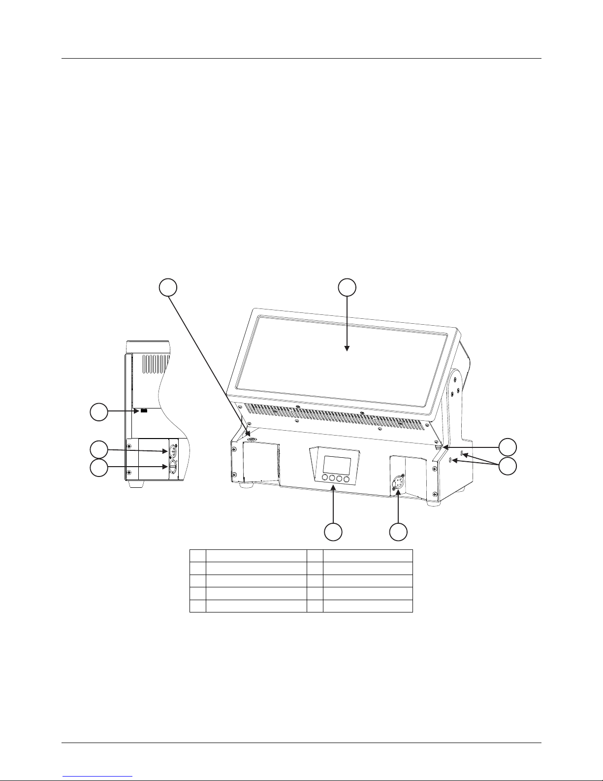
2.2 Parts Identification
1
fuse holder
6
control panel
2
head
7
AC mains socket
3
alignment pin lever
8
DMX in socket
4
alignment pins
9
tilt lock lever
5
DMX out socket
Figure 2-1
2.3 Strobe
The JDC1 provides a traditional single-tube element created with 216 LEDs that
produce an incredibly clear, bright white output. The LEDs flash at up to 16.67 Hz
and can be run continuously for high output blinder and wash effects with an
86° beam angle. Control of the tube is divided into 12 ‘pixel’ segments.
1 2
3
4
56
7
8
9
Page 7

German Light Products GmbH JDC1
User Manual Rev. 1.0 7
2.4 Color
The JDC1 provides two large-array RGB color plates surrounding the strobe tube.
Each plate is divided into six independently controllable 110 LED ‘pixels’ that
flash and operate continuously, providing a wide (148°) color wash.
2.5 Dimming and Shutter Effects
Three dimming curves are available: linear, soft, and extra soft. Select the
desired mode from the control panel.
2.6 Tilt
The JDC1 head tilts through 185° with coarse and fine control channels and selfcorrecting position feedback. Position feedback can be disabled and control
can be reversed from the control panel.
2.7 Changing Settings by DMX
The Control Channel (7 in Normal DMX Mode) provides the ability to adjust the
pulse width modulation (PWM) frequency in 1 Hz increments from 582 to 618 Hz,
or set to 1200 or 2400 Hz. It also provides commands to toggle FX/Pattern Color
Priority on/off, and perform a fixture reset.
2.8 Display
The illuminated graphic LCD display with self-charging battery allows you to
change fixture settings quickly and intuitively under any conditions, even when
the power is off. See Chapter 4 for settings, readouts, and related information.
2.9 Clamp Attachment
The base provides Camlock attachment points for easy fastening of an omega
clamp attachment bracket that accepts two half-coupler clamps.
Page 8
WWW.GLP.DE JDC1
8 User Manual Rev. 1.0
3 Preparation for Use
3.1 Included Items
The JDC1 package includes a power cord with Neutrik powerCON TRUE1
connector and an omega bracket (part no. 87036).
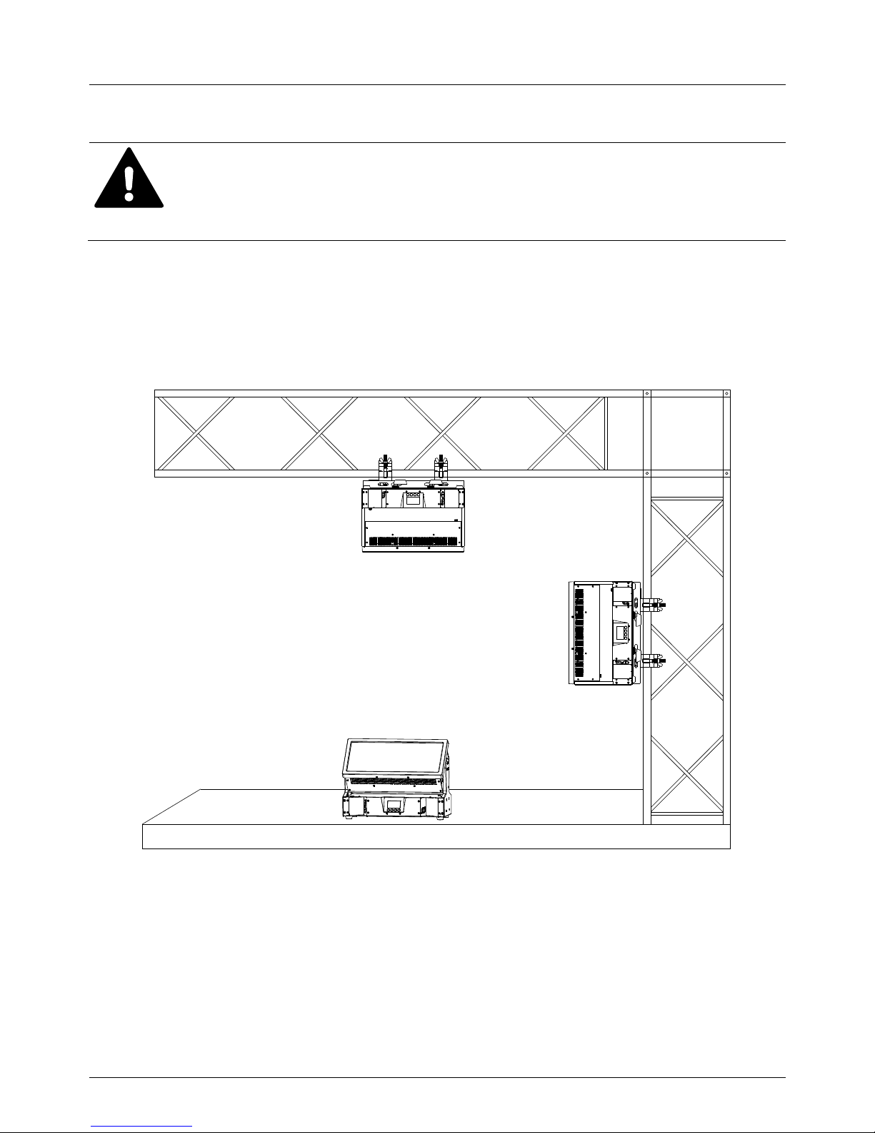
3.2 Mounting
The JDC1 may be rigged in any orientation or placed on a level surface. When
installing, keep the head at least 1 m (3.3 ft.) from flammable materials including
curtains and stage scenery.
An omega bracket for attaching two half-couplers is included.
Installation shall be performed by qualified personnel only, in
accordance with applicable regulations such as BGV C1 and DIN VDE
0711-217.
Figure 3-1: Mounting Options (safety cable not shown)
Page 9

German Light Products GmbH JDC1
User Manual Rev. 1.0 9
Mounting Upright on a Level Surface
The JDC1 may be placed upright on a level surface.
Precautions shall be taken to avoid accidental
contact.
To align multiple units, insert the alignment pins on the
right side of one fixture into the alignment holes on the
left side of the next fixture.
Head Down or Sideways Truss Mounting
To hang the JDC1 with the head down or sideways,
bolt two suitable half-coupler rigging clamps to the omega clamp attachment
bracket. Fasten the bracket to the base with four Camlock quarter-turn pins.
Line up and insert the pins into the base and turn 90° clockwise to lock. Do the
opposite to release them.
Fasten the rigging clamps securely to the truss. Secure as directed in section 3.3.
3.3 Securing the Device
Warning! Use a secondary attachment (safety wire) that can hold at least 10
times the weight of the fixture whenever hanging the fixture. Clip the safety wire
to the cable eye on the back of base.
Figure 3-4: Safety Cable Attachment Point
Figure 3-3: Camlock Sockets
Figure 3-2: Alignment
Page 10

WWW.GLP.DE JDC1
10 User Manual Rev. 1.0
3.4 Connections
Power
The JDC1 provides a 3-conductor, 20 A Neutrik powerCON TRUE1 socket for
connection to AC power. The autosensing power supply accepts 100-240 V,
50/60 Hz AC power. Do not connect to any other voltage or an external dimmer.
The main fuse is located in a holder in the base. WARNING! Always disconnect
the fixture from the mains supply before replacing the fuse. Replace only with
fuse of the specified type.
Control Data
The JDC1 provides 5-pin XLR input/output sockets for connection to a USITT DMX512 Standard data link. The pin connections are Pin 1 = [Ground] / Pin 2 = [-] /
Pin 3 = [+]. Pins 4 & 5 on the 5-pin sockets have no contact.
3.5 Start/stop operation
Verify that the tilt lock has been released before operating. Apply power to start
operation. Disconnect from power to stop operation.
3.6 Transportation and Storage
The JDC1 should be transported either in a flight case or its original packaging
to protect it from damage from shocks during transportation. Lock the head in
the horizontal position for transport by sliding the tilt lock lever to the locked
position.
When not installed, store the fixture in a dry location.
The AC supply shall provide earth ground connection and overload
protection. Before applying power, verify that there is adequate
clearance around the fixture, that there is no filter or other object on
the front glass, and that the head is unlocked and can move freely.
Page 11

German Light Products GmbH JDC1
User Manual Rev. 1.0 11
4 The Menu Field
The LCD display provides access to user settings, readouts, and utilities including
manual control and a test routine.
From left to right, the top line of the main menu displays:
main CPU software version
DMX control modes for tilt, all pixels, color plate 2: N(ormal) or I(nverted)
DMX mode number
dimming mode: L(inear), S(oft), or E(xtra Soft)
PWM frequency in Hz
For example, if the top line reads “V:1.25/NNN/M02/E 600”, then:
the main CPU software is version 1.25,
DMX control for tilt, all pixels, and color plate 2 is set to normal,
DMX mode 2 is selected,
dimming mode is set to extra soft, and
PWM frequency is set to 600 Hz.
When booting up, the panel displays fixture information including component
firmware and hardware versions and fixture hours before displaying the PCB
reset status screen. After resetting, the panel displays the main menu.
The bottom row displays button functions. Press the Mode button to escape and
return to the top of the menu. Press the Enter button to select a setting, issue a
command, or enter a submenu. Press the Down and Up buttons to scroll menu
options.
To return resettable counters to zero, press and hold Enter for 3 seconds with the
counter displayed.
DMX control is disabled when the menu is active. A flashing display indicates loss
of DMX.
Page 12

WWW.GLP.DE JDC1
12 User Manual Rev. 1.0
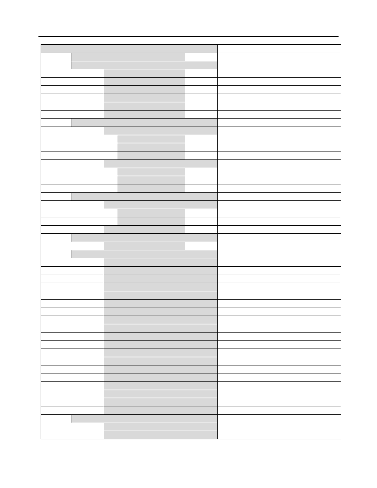
Menu Selection
Value
Remarks
DMX Start Address
1-512
Set the DMX start address
Setup
DMX Mode
M01 COMPRESS
-
Compressed 14-channel mode
M02 NORMAL
-
Normal 23-channel mode
M03 SPIX
-
High resolution 68-channel mode
M04 SPIXPRO
-
High resolution 62-channel mode
M05 1PIXPRO
-
Low resolution 17-channel mode
Settings
Tilt Invert Tilt
ON/OFF
Invert tilt control
Position Feedback
ON/OFF
Toggle feedback
Tilt Enable
ON - Tilt enabled and DMX controllable
OFF
-
Tilt disabled
NC - Tilt enabled, not DMX controllable
Shutter
Error Blackout
ON/OFF
Blackout in case of error
No DMX Blackout
ON/OFF
Blackout if no DMX for 3 seconds
Init Positions
Save
-
Save as initial positions
Reset
-
Restore default positions
Dimming Curve
Linear
-
Soft
-
Extra Soft
-
DMX Hold
Off - Blackout on loss of DMX
Fade Out
-
Fade out on loss of DMX
Hold
-
Hold state on loss of DMX
PWM Frequency
Adjust pulse width modulation freq.
582-618 Hz
-
Default = 600 Hz
1200 Hz
-
2400 Hz
-
FX Pattern Priority
ON/OFF
Display
Contrast
0-100%
Default = 50%
Brightness
0-100%
Default =100%
Blackout Time
1-30 s
Display off (seconds after keypress)
Display Orientation
Normal
-
Normal display
Inverted
-
Inverted display
No DMX Flash
ON/OFF
Toggle flash on DMX loss
Temperature Unit
°C/°F
Fan Mode
Auto
-
Temperature controlled fan speed
High
-
Maximum cooling
Reset Factory Settings
Yes/No
Resets all values except serial number
Page 13
German Light Products GmbH JDC1
User Manual Rev. 1.0 13
Information
System Errors
List
Display recent errors
System Versions
Display firmware and hardware versions
Main
SW/HW
Tilt
SW/HW
NM-LED A
SW/HW
NM-LED B
SW/HW
NM-LED C
SW/HW
NM-LED D
SW/HW
Temperatures
Main Temperature
Current
°C/°F
Max. Resettable
°C/°F
Maximum temperature since last reset
Max. Non-resettable
°C/°F
All time maximum temperature
LED Temperature
Current
°C/°F
Max. Resettable
°C/°F
Maximum temperature since last reset
Max. Non-resettable
°C/°F
All time maximum temperature
Fixture Information
Fixture Hours
Total hours
hours
Total hours
Resettable hours
hours
Hours since last reset
Boot Count
count
Fixture Status
Power State
BAT/PO
Battery or AC mains power
DMX Input Monitor
Displays DMX levels
Tilt
0-255
Special / Control
0-255
Beam FX Shutter
0-255
Beam Dimmer
0-255
Beam Duration
0-255
Beam Rate
0-255
Color Shutter
0-255
FX Color Dimmer
0-255
Color Duration
0-255
Color Rate
0-255
Plate Red
0-255
Plate Green
0-255
Plate Blue
0-255
FX Crossfade
0-255
Pattern Color Movement
0-255
Pattern Select Color
0-255
Pattern Beam Movement
0-255
Pattern Select Beam
0-255
Master Pix Intensity
0-255
Fans Monitor
Display fan speed and voltage
PSU Fan
RPM/V
Head Fan
RPM/V
Page 14

WWW.GLP.DE JDC1
14 User Manual Rev. 1.0
Manual Control
Reset
Full System Reset
YES/NO
Tilt Reset
YES/NO
NM_LED L Driver
YES/NO
NM_LED R Driver
YES/NO
Manual DMX
Enter control values
Tilt
0-255
Special / Control
0-255
Beam FX Shutter
0-255
Beam Dimmer
0-255
Beam Duration
0-255
Beam Rate
0-255
Color Shutter
0-255
Color Dimmer
0-255
Color Duration
0-255
Color Rate
0-255
FX Color Dimmer
0-255
Plate Red
0-255
Plate Green
0-255
Plate Blue
0-255
FX Crossfade
0-255
Pattern Color Movement
0-255
Pattern Select Color
0-255
Pattern Beam Movement
0-255
Pattern Select Beam
0-255
Master Pix Intensity
0-255
Reset All Values
YES/NO
Set all manual DMX values to 0
Test
Tilt
ON/OFF
Color
ON/OFF
All
ON/OFF
Service
Key Code
0-255
Enter code for Service Menu.
Serial
0-99999
Last 5 digits of serial no. (for RDM)
Tilt
0-255
Default =128
Table 1 Control Menu: Default settings in BOLD type.
Page 15

German Light Products GmbH JDC1
User Manual Rev. 1.0 15
5 DMX Channels
The JDC1 may be operated in 5 DMX modes that use from 14 to 68 channels.
The commands for each mode are listed in the following tables.
The layout of channels 1-14 is the same in each mode. To avoid repetition, these
channels are only listed in the table for Mode 1. For modes 2-5, the tables list
channels 15 and above.
Page 16

WWW.GLP.DE JDC1
16 User Manual Rev. 1.0
5.1 Mode 1, Compressed Pro, 14 DMX Channels
Channel
Command
Percent
DMX
1
Coarse Tilt (MSB)
0-182°
0-100%
0-255
2
Fine Tilt (LSB)
coarse tilt + 0-1.2°
0-100%
0-255
3
Beam Intensity
blackout to full
0-100%
0-255
4
Beam Duration
7-650 ms
0-100%
0-255
5
Beam Rate
0.289-16.67 Hz
0-100%
0-255
6
Beam FX Shutter
no effect
0-14.0%
0-36
ramp up (= fade on, snap off)
14.5-15.5%
37-40
ramp up random
16.0-17.0%
41-44
ramp down
17.5-18.5%
45-48
ramp down random
19.0-20.0%
49-52
ramp up down
20.5-21.5%
53-56
ramp up down random
22.0-23.0%
57-60
random white beam
23.5-24.5%
61-64
random single pixel of the white beam
25.0-26.0%
65-68
lightning
26.5-27.5%
69-72
spikes (flash over low light)
28.0-29.0%
73-76
white beam, left to right
30.0-31.5%
77-80
white beam, left to right, random
32.0-33.0%
81-84
white beam, right to left
33.5-34.5%
85-88
white beam, right to left, random
35.0-36.0%
89-92
white beam, left to right, bounce
36.5-37.5%
93-96
white beam, left to right, bounce, random
38.0-39.0%
97-100
white beam, right to left, bounce
39.5-40.5%
101-104
white beam, right to left, bounce, random
41.0-42.5%
105-108
zig, 6 steps
43.0-43.5%
109-112
zig, 6 steps, random
44.0-45.5%
113-116
zig, 6 steps, outer to center pixel
46.0-47.0%
117-120
zig, 6 steps, outer to center pixel, random
47.5-48.5%
121-124
zigzag, 10 steps
49.0-50.0%
125-128
zigzag, 10 steps, random
50.5-52.0%
129-132
reserved
52.5-70.0%
133-179
double flash
70.6-71.8%
180-183
double flash, random
72.2-73.3%
184-187
double flash, beam-color
73.7-74.9%
188-191
double flash, beam-color, random
75.3-76.5%
192-195
double flash, color-beam
76.9-78.0%
196-199
double flash, color-beam, random
78.4-79.6%
200-203
triple flash
80.0-81.2%
204-207
triple flash, random
81.6-82.7%
208-211
triple flash, beam-color-beam
83.1-84.3%
212-215
triple flash, b-c-b, random
84.7-85.9%
216-219
triple flash, c-b-c
86.3-87.5%
220-223
triple flash, c-b-c, random
87.8-89.0%
224-227
quad flsh
89.4-90.6%
228-231
quad flash, random
91.0-92.2%
232-235
quad flash, b-c-b-c
92.5-93.7%
236-239
quad flash, b-c-b-c, random
94.1-95.3%
240-243
quad flash, c-b-c-b
95.7-96.9%
244-247
quad flash, c-b-c-b, random
97.3-98.4%
248-251
reserved
98.5-100%
252-255
Page 17

German Light Products GmbH JDC1
User Manual Rev. 1.0 17
7
Special / Control
No Function
0%
0
Channel 4-6 Offset
10°
0.4%
1
20°
0.8%
2
30°
1.2%
3
40°
1.6%
4
50°
2.0%
5
60°
2.4%
6
70°
2.8%
7
80°
3.1%
8
90°
3.5%
9
100°
3.9%
10
110°
4.3%
11
120°
4.7%
12
130°
5.1%
13
140°
5.5%
14
150°
5.9%
15
160°
6.3%
16
170°
6.7%
17
180°
7.1%
18
190°
7.5%
19
200°
7.8%
20
210°
8.2%
21
220°
8.6%
22
230°
9.0%
23
240°
9.4%
24
250°
9.8%
25
260°
10.2%
26
270°
10.6%
27
280°
11.0%
28
290°
11.4%
29
300°
11.8%
30
310°
12.2%
31
320°
12.6%
32
330°
12.9%
33
340°
13.3%
34
350°
13.7%
35
360°
14.1%
36
No Function
14.5-15.3%
37-39
Position Feedback On
15.7-17.3%
40-44
Position Feedback Off
17.7-19.2%
45-49
FX/Pattern Color Priority On (Hold > 3 secs)
19.6-21.2%
50-54
FX/Pattern Color Priority Off (Hold > 3 secs)
21.6-23.1%
55-59
Pixel H
23.5-25.1%
60-64
Pixel V
25.5-27.1%
65-69
Normal Tilt Control
27.5-29.0%
70-74
Inverse Tilt Control
29.4-31.0%
75-79
Normal Pixel Orientation
31.4-32.9%
80-84
Inverse Pixel Orientation
33.3-34.9%
85-89
Normal Orientation, 2nd Pixel Line
35.3-36.9%
90-94
Inverse Orientation, 2nd Pixel Line
37.3-38.8%
95-99
Page 18

WWW.GLP.DE JDC1
18 User Manual Rev. 1.0
7
Special / Control
PWM Frequency
582 Hz
39.2-40.0%
100-102
583 Hz
40.4-41.2%
103-105
584 Hz
41.6-42.0%
106-107
585 Hz
42.4-43.1%
108-110
586 Hz
43.5 43.9%
111-112
587 Hz
44.3 -45.1%
113-115
588 Hz
45.5-46.3%
116-118
589 Hz
46.7-47.1%
119-120
590 Hz
47.5-48.2%
121-123
591 Hz
48.6-49.0%
124-125
592 Hz
49.4-50.2%
126-128
593 Hz
50.6-51.4%
129-131
594 Hz
51.8-52.2%
132-133
595 Hz
52.5-53.3%
134-136
596 Hz
53.7-54.1%
137-138
597 Hz
54.5-55.3%
139-141
598 Hz
55.7-56.5%
142-144
599 Hz
56.9-57.3%
145-146
600 Hz
57.6-58.4%
147-149
601 Hz
58.8-59.2%
150-151
602 Hz
59.6-60.4%
152-154
603 Hz
60.8-61.6%
155-157
604 Hz
62.0-62.4%
158-159
605 Hz
62.7-63.5%
160-162
606 Hz
63.9-64.3%
163-164
607 Hz
64.7-65.5%
165-167
608 Hz
65.9-66.7%
168-170
609 Hz
67.1-67.5%
171-172
610 Hz
67.8-68.6%
173-175
611 Hz
69.0-69.4%
176-177
612 Hz
69.8-70.6%
178-180
613 Hz
71.0-71.8%
181-183
614 Hz
72.2-72.5%
184-185
615 Hz
72.9-73.7%
186-188
616 Hz
74.1-74.5%
189-190
617 Hz
74.9-75.7%
191-194
618 Hz
76.1-76.1%
194-194
1200 Hz
76.5-77.3%
195-197
2400 Hz
77.6-78.4%
198-200
No Function
79.0-82.0%
201-209
Duration Percentage Mode On
82.5-84.0%
210-214
Duration Percentage Mode Off
84.5-85.0%
215-219
Dimmer Flash On
86.0-87.5%
220-224
Dimmer Flash Off
88.0-90.0%
225-229
FX/Plate Color Priority On
90.5-91.5%
230-234
FX/Plate Color Priority Off
92.0-93.5%
235-239
No Function
94.0-97.0%
220-247
Reset (Hold > 5 seconds)
98.0-100%
248-255
Page 19

German Light Products GmbH JDC1
User Manual Rev. 1.0 19
8
Color Plate Intensity
blackout to full
0-100%
0-255
9
Color Flash Duration
7-650 ms
0-100%
0-255
10
Color Flash Rate
0.289-16.67 Hz
0-100%
0-255
11
Color FX Shutter
No function
0%
0
Color Plate Offset
10°
0.4%
1
20°
0.8%
2
30°
1.2%
3
40°
1.6%
4
50°
2.0%
5
60°
2.4%
6
70°
2.8%
7
80°
3.1%
8
90°
3.5%
9
100°
3.9%
10
110°
4.3%
11
120°
4.7%
12
130°
5.1%
13
140°
5.5%
14
150°
5.9%
15
160°
6.3%
16
170°
6.7%
17
180°
7.1%
18
190°
7.5%
19
200°
7.8%
20
210°
8.2%
21
220°
8.6%
22
230°
9.0%
23
240°
9.4%
24
250°
9.8%
25
260°
10.2%
26
270°
10.6%
27
280°
11.0%
28
290°
11.4%
29
300°
11.8%
30
310°
12.2%
31
320°
12.6%
32
330°
12.9%
33
340°
13.3%
34
350°
13.7%
35
360°
14.1%
36
ramp up (fade on, snap off)
14.5-15.5%
37-40
ramp up, random
16.0-17.0%
41-44
ramp down
17.5-18.5%
45-48
ramp down, random
19.0-20.0%
49-52
ramp up / down
20.5-21.5%
53-56
ramp up / down, random
22.0-23.0%
57-60
random white beam
23.5-24.5%
61-64
random single pixel of the white beam
25.0-26.0%
65-68
lightning
26.5-27.5%
69-72
spikes (flash over low light)
28.0-29.0%
73-76
reserved
29.5-70.0%
77-179
double flash
70.6-74.9%
180-191
Page 20

WWW.GLP.DE JDC1
20 User Manual Rev. 1.0
11
Color FX Shutter
double flash, random
75.3-79.6%
192-203
triple flash
80.0-84.3%
204-215
triple flash, random
84.7-89.0%
216-227
quad flash
89.4-93.7%
228-239
quad flash, random
94.1-98.4%
240-251
no effect
98.5-100%
252-255
12
Plate Red Intensity
blackout to full
0-100%
0-255
13
Plate Green Intensity
blackout to full
0-100%
0-255
14
Plate Blue Intensity
blackout to full
0-100%
0-255
5.2 Mode 5, 1Pix Pro, 17 DMX Channels
Channel
Command
Percent
DMX
See Mode 1 for Channels 1-14
15
Color Set 2, Red intensity
0-100%
0-255
16
Color Set 2, Green intensity
0-100%
0-255
17
Color Set 2, Blue intensity
0-100%
0-255
5.3 Mode 2, Normal, 23 DMX Channels
Channel
Command
Percent
DMX
See Mode 1 for Channels 1-14
15
FX Crossfade
0-100%
0-255
16
Pattern Color Movement
0-100%
0-255
17
Pattern Select Color
0-100%
0-255
18
Pattern Beam Movement
0-100%
0-255
19
Pattern Select Beam
0-100%
0-255
20
Color Set 2, Master Intensity
blackout to full
0-100%
0-255
21
Color Set 2, Red intensity
blackout to full
0-100%
0-255
22
Color Set 2, Green intensity
blackout to full
0-100%
0-255
23
Color Set 2, Blue intensity
blackout to full
0-100%
0-255
Page 21

German Light Products GmbH JDC1
User Manual Rev. 1.0 21
5.4 Mode 4, SPix Pro, 62 DMX Channels
Channel
Command
Percent
DMX
See Mode 1 for Channels 1-14
15
Pixel 1
Red 0-100%
0-255
16
Green 0-100%
0-255
17
Blue 0-100%
0-255
18
Pixel 2
Red 0-100%
0-255
19
Green 0-100%
0-255
20
Blue 0-100%
0-255
21
Pixel 3
Red 0-100%
0-255
22
Green 0-100%
0-255
23
Blue 0-100%
0-255
24
Pixel 4
Red 0-100%
0-255
25
Green 0-100%
0-255
26
Blue 0-100%
0-255
27
Pixel 5
Red 0-100%
0-255
28
Green 0-100%
0-255
29
Blue 0-100%
0-255
30
Pixel 6
Red 0-100%
0-255
31
Green 0-100%
0-255
32
Blue 0-100%
0-255
33
Pixel 7
Red 0-100%
0-255
34
Green 0-100%
0-255
35
Blue 0-100%
0-255
36
Pixel 8
Red 0-100%
0-255
37
Green 0-100%
0-255
38
Blue 0-100%
0-255
39
Pixel 9
Red 0-100%
0-255
40
Green 0-100%
0-255
41
Blue 0-100%
0-255
42
Pixel 10
Red 0-100%
0-255
43
Green 0-100%
0-255
44
Blue 0-100%
0-255
45
Pixel 11
Red 0-100%
0-255
46
Green 0-100%
0-255
47
Blue 0-100%
0-255
48
Pixel 12
Red 0-100%
0-255
49
Green 0-100%
0-255
50
Blue 0-100%
0-255
51
White Intensity
Pixel 1 0-100%
0-255
52
Pixel 2 0-100%
0-255
53
Pixel 3 0-100%
0-255
54
Pixel 4 0-100%
0-255
55
Pixel 5 0-100%
0-255
56
Pixel 6 0-100%
0-255
57
Pixel 7 0-100%
0-255
58
Pixel 8 0-100%
0-255
59
Pixel 9 0-100%
0-255
60
Pixel 10
0-100%
0-255
61
Pixel 11
0-100%
0-255
62
Pixel 12
0-100%
0-255
Page 22

WWW.GLP.DE JDC1
22 User Manual Rev. 1.0
5.5 Mode 3, SPix, 68 DMX Channels
Channel
Command
Percent
DMX
See Mode 1 for Channels 1-14
15
FX Crossfade
0-100%
0-255
16
Pattern Color Movement
0-100%
0-255
17
Pattern Select Color
0-100%
0-255
18
Pattern Beam Movement
0-100%
0-255
19
Pattern Select Beam
0-100%
0-255
20
Master Pix Intensity
0-100%
0-255
21
Pixel 1
Red 0-100%
0-255
22
Green 0-100%
0-255
23
Blue 0-100%
0-255
24
Pixel 2
Red 0-100%
0-255
25
Green 0-100%
0-255
26
Blue 0-100%
0-255
27
Pixel 3
Red 0-100%
0-255
28
Green 0-100%
0-255
29
Blue 0-100%
0-255
30
Pixel 4
Red 0-100%
0-255
31
Green 0-100%
0-255
32
Blue 0-100%
0-255
33
Pixel 5
Red 0-100%
0-255
34
Green 0-100%
0-255
35
Blue 0-100%
0-255
36
Pixel 6
Red 0-100%
0-255
37
Green 0-100%
0-255
38
Blue 0-100%
0-255
39
Pixel 7
Red 0-100%
0-255
40
Green 0-100%
0-255
41
Blue 0-100%
0-255
42
Pixel 8
Red 0-100%
0-255
43
Green 0-100%
0-255
44
Blue 0-100%
0-255
45
Pixel 9
Red 0-100%
0-255
46
Green 0-100%
0-255
47
Blue 0-100%
0-255
48
Pixel 10
Red 0-100%
0-255
49
Green 0-100%
0-255
50
Blue 0-100%
0-255
51
Pixel 11
Red 0-100%
0-255
52
Green 0-100%
0-255
53
Blue 0-100%
0-255
54
Pixel 12
Red 0-100%
0-255
55
Green 0-100%
0-255
56
Blue 0-100%
0-255
57
White Intensity
Pixel 1 0-100%
0-255
58
Pixel 2 0-100%
0-255
59
Pixel 3 0-100%
0-255
60
Pixel 4 0-100%
0-255
61
Pixel 5 0-100%
0-255
62
Pixel 6 0-100%
0-255
63
Pixel 7 0-100%
0-255
64
Pixel 8 0-100%
0-255
65
Pixel 9 0-100%
0-255
66
Pixel 10
0-100%
0-255
67
Pixel 11
0-100%
0-255
68
Pixel 12
0-100%
0-255
Page 23

German Light Products GmbH JDC1
User Manual Rev. 1.0 23
6 Cleaning and Maintenance
6.1 Suggested Maintenance Intervals
The cleaning schedule depends on the operating environment. The intervals
below are suggestions from our experience with typical installations. Adjust as
necessary.
Maintenance Task
Interval
How
Front glass
weekly
soft cloth and glass cleaning fluid
Fans and air channel
monthly
vacuum cleaner, compressed air, etc.
Moveable parts
yearly
suitable lubricant
6.2 Cleaning
JDC1 components require occasional cleaning to prevent the buildup of dust,
dirt, and smoke fluid residue. Pay special attention to the air vents and glass
plate. Failure to keep the fixture clean will significantly reduce light output and
may cause damage. Regular cleaning will ensure the maximum performance
and reliable operation.
The glass plate may be cleaned with household or automotive glass cleaning
products.
6.3 GLP Service and Support
Contact information for the nearest GLP service and suport is available online
at www.glp.de/en/service, by email at info@glp.de, or by telephone at the
following numbers:
GLP Germany: +49 (7248) 927 19-55
GLP N. America: +1 818 767-8899
GLP U.K.: +44 1392 690140
GLP Asia: +852 (3151) 7730
GLP Nordic: +46 737 57 11 40
WARNING! Any service operation that requires removal of a cover shall
be performed by a professional service technician with the tools, skills,
and personal protective equipment to maintain high-powered lighting
equipment safely and efficiently.
Page 24

WWW.GLP.DE JDC1
24 User Manual Rev. 1.0
7 Technical Specifications
Strobe Panel LEDs
LED Type
OSRAM LRTB GVTG
LED Count
1320
LED Colors
RGB
LED Segments
12 (2 x 6)
Strobe Tube LEDs
LED Type
CREE XP L LED
LED Count
216
LED Colors
Cool White
LED Segments
12
Movement
Resolution
8 - 16 Bit
Position feedback
yes
Tilt
185 °
Connectors
Signal connection
XLR 5-pin input & output
Power input
Neutrik powerCON TRUE1
Operating Conditions
Mains voltage
100-240 VAC / 50-60Hz
Power (@ 230V)
1200 W
Fuse
6.3X32mm T15A
Max. ambient temp.
45°C / 113°F
Operating position
any
Shipping
Single fixture
cardboard (Product code 7675)
Tourpacks
4-way & 8-way incl. flightcase
Dimensions & Weight
Length
154 mm (6.1 in)
Width
390 mm (15.3 in)
Height (head horizontall)
284 mm (11.2 in)
Weight
10.8 kg (24 lbs)
Weight incl. bracket
12 kg (26.5 lbs)
Page 25
German Light Products GmbH JDC1
User Manual Rev. 1.0 25
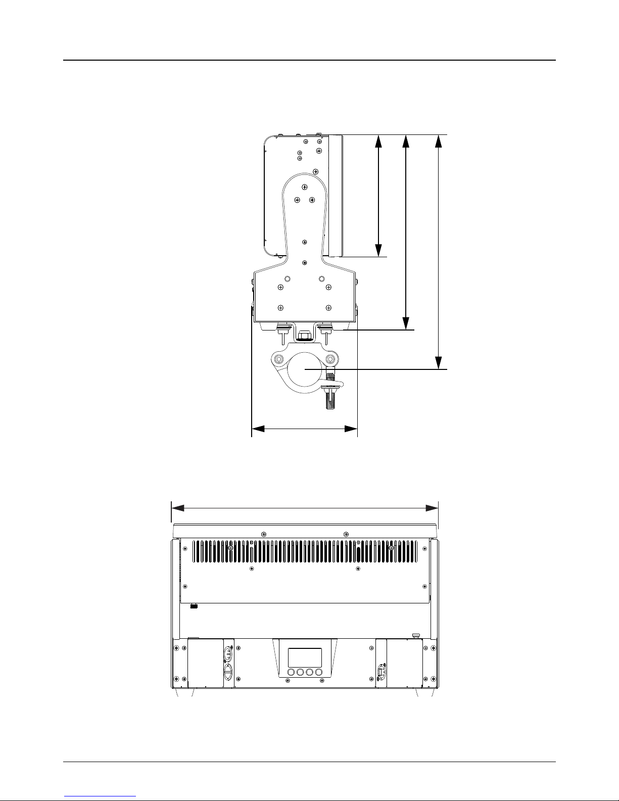
8 Dimensions
178 mm
284 mm
342 mm
154 mm
390 mm
Page 26

 Loading...