

Page 1
User Manual
So
ftware v. 28-40-28-2
7
Page 2

GLP® impression S350 User Manual Revision A
This user manual covers fixture software version v. 28-40-28-27
© 2018 German Light Products GmbH. All rights reserved.
The marks ‘GLP’, ‘German Light Products’ and ‘impression’ are trademarks registered as the property
of German Light Products GmbH in Germany, in the United States of America and in other countries.
The information contained in this document is subject to change without notice. German Light
Products GmbH and all affiliated companies disclaim liability for any injury, damage, direct or
indirect loss, consequential or economic loss or any other loss occasioned by the use of, inability to
use or reliance on the information contained in this document.
Manufacturer head office:
German Light Products GmbH (GLP), Industriestrasse 2, 76307 Karlsbad, Germany
Tel (Germany): +49 7248 92719 - 0
Service & Support EMEA:
GLP, Industriestrasse 2, 76307 Karlsbad, Germany
Tel. (Germany): +49 7248 9271955
Email: support@glp.de
www.glp.de
Service & Support USA:
GLP USA, 1145 Arroyo St., Ste. A, 91340 San Fernando, California
Tel (USA): +1 818 767 8899
Support (US): info@germanlightproducts.com
www.germanlightproducts.com
Page 3

Contents
1. Safety .................................................................................... 4
2. Avoiding damage .............................................................. 9
3. Product overview .............................................................. 11
4. Product features ............................................................... 12
5. Preparation for use ........................................................... 19
6. Control menus and LCD display .................................... 23
7. Control menu layout ........................................................ 25
8. DMX channel layout......................................................... 29
9. Caring for your product ................................................... 36
10. Troubles hooti ng ................................................................. 37
11. Technical specifications .................................................. 38
12. Dimensions ......................................................................... 41
Page 4
www.glp.de
4 GLP® impression S350
User Manual Rev. A
1. Safety
Key to symbols
The following symbols are used in this manual:
General safety information
• Read this section carefully before installing or using the impression S350 lighting fixture.
If you have any doubts or questions about how to use the product safely, contact
your GLP® supplier for assistance.
• The product and this user manual are intended for use by experienced professionals
with the knowledge and skills to set up, operate, and maintain high-powered,
remotely controlled lighting equipment safely and efficiently. These operations require
expertise that may not be provided in this manual.
• Respect all warnings and directions given in this user manual and on the product.
Read this manual and familiarize yourself with the safety precautions it contains
before installing or using the product. The manufacturer will take no responsibility for
damages or harm resulting from disregard for the information in this manual.
• Check the GLP website at www.glp.de and make sure that you have the latest
version of this user manual. Check the fixture software version indicated on page 2 of
this user manual and then use the fixture’s control panel to check the version installed
in the fixture. If the versions are not the same, the user manual may still cover the
fixture (software updates do not always affect the way you use the fixture), but it is
possible that the manual does not match the fixture perfectly. The software release
notes should help clarify this question. You can consult software release notes and
download the correct version of this user manual on the GLP website if necessary.
Warning! Safety hazard.
Risk of severe injury or
death.
Warning! Hazardous voltage.
Risk of lethal or severe
electric shock.
Warning! See user
manual for important
safety information.
Warning! Fire hazard.
Warning! Risk of eye
injury.
Page 5
German Light Products®
GLP® impression S350 User Manual 5
• Make the user manual available to all installers and operators and save the manual
for future reference.
• If you have questions about the safe operation of the impression S350, please contact
an authorized GLP distributor (see list of distributors at www.glp.de).
• Use the product only as directed in this user manual. Observe all markings in this user
manual and on the product.
• Refer any service operation not described in this manual and refer all repairs to a
technician authorized by GLP.
• The light source in this product must not be changed by the end user.
• Read and follow the user documentation for all additional equipment.
Electrical safety
• Do not allow the product to come into contact with water or moisture.
• Use only a source of AC mains power that complies with local building and electrical
codes and has both overload and ground fault (earth fault) protection.
• Ensure that the product is electrically connected to ground (earth).
• Disconnect the product from AC mains power before carrying out any installation or
maintenance work and when the product is not in use.
• Disconnect the product from power immediately if the power plug or any seal, cover,
cable, or other component is damaged, defective, deformed, wet or showing signs
of overheating. Do not reapply power until the product has been repaired and made
safe by a technician authorized by GLP.
• Before using the product, check that all power distribution equipment and cables are
in perfect condition and rated for the electrical requirements of all connected
devices.
• Use only a Neutrik powerCON TRUE1 cable connector for AC power input at the
product’s power connector.
• Use minimum 14 AWG or 1.5 mm
2
power input and relay cables that are minimum
16 A rated and temperature-rated to suit the application. In the USA and Canada the
cables must be UL-listed, type SJT or equivalent. In the EU the cables must be type
H05VV-F or equivalent.
• The supplied power input cable is rated as follows:
- US power cable: 16 A, 14 AWG, UL listed, E304117, SJT, 4.9 ft.
- EU power cable: 16 A, 1.5mm², H05VV-F, 1.5 m
• If a fuse blows, replace it with one of the original type and rating only. If new fuses
blow, disconnect the product from power and send it to a technician authorized by
GLP for repair.
Page 6
www.glp.de
6 GLP® impression S350
User Manual Rev. A
Fire safety and protection from burns
• Do not operate the product if the ambient temperature (Ta) exceeds 45° C (115° F).
• The surface of the product’s casing can reach up to 55° C (131° F) during operation.
Avoid contact by persons and materials. Do not install the product in a location
where there is a risk of accidental contact. Allow the product to cool for at least 10
minutes before handling.
• Keep the product well away from flammable materials.
• Keep all combustible materials (e.g. fabric, wood, paper) at least 200 mm (8 in.)
away from the product.
• Ensure that there is free and unobstructed airflow around the product. Provide a
minimum clearance of 100 mm (4 in.) around fans and air vents.
• Do not illuminate surfaces within 2 m (6.6 ft.) of the product.
• Do not install a fuse that has a higher rating than the one originally installed in the
product. Do not bypass fuses.
• Do not stick filters, masks or other materials onto optical components.
• If the fixture seems to be abnormally hot, shows signs of melting or emits smoke,
disconnect the fixture from power immediately and allow it to cool. Do not touch the
fixture without heatproof safety gloves. Keep the fixture well away from combustible
and flammable materials.
• The product’s optical components can focus the sun’s rays, creating a risk of fire and
damage. Do not expose the front of the product to sunlight or any other intense light
source, even from an angle.
Eye safety
• The impression S350 is classified as a Risk Group 2 product according to DIN EN
62471:2009-03. Possibly hazardous radiation emitted. Do not stare into the light output
from the product. May be harmful to the eyes.
• Do not look at the product’s light output with optical instruments or any device that
may concentrate the light output.
• Make sure that persons working on or near the product are not looking directly into
the light output when the product lights up suddenly. This can happen when power is
applied, when the product receives a DMX signal, or when certain control menu
items are selected.
• Provide well-lit conditions to reduce the pupil diameter of anyone working on or near
the product.
Page 7
German Light Products®
GLP® impression S350 User Manual 7
Strobe safety
• Flashing light, particularly at 5 - 30 Hz, may cause seizures in persons with
photosensitive epilepsy. Do not use strobe effects for extended periods.
• Comply with local regulations on the use of strobe lighting and notify the public in
advance with highly visible warning signs when strobe effects are used.
• If a seizure occurs, stop using strobe effects. Seek professional medical help. Note the
time that the seizure starts and finishes. Call emergency medical help urgently if the
seizure lasts more than five minutes, if it is the person’s first seizure, or if the person is
injured. While waiting for help to arrive, consider the following general advice for
caring for a person who is having a seizure: protect the affected person from injuring
themselves on hard or sharp objects. If necessary, move the person to a safe place.
Lay them on their side with their head supported to prevent it from hitting the floor.
Loosen any tight clothing around their neck. Do not use force to hold the person or
restrict their movements. Do not put anything in their mouth, including your fingers.
Installation and operation safety
• The fixture must be installed and operated by qualified personnel only and in
accordance with applicable regulations such as DIN VDE 0711-217.
• The fixture is not portable when installed.
• Ensure that the supporting structure and installation hardware used can hold at least
10 times the weight of the load that they support.
• Install the fixture with hardware specifically designed and rated for the purpose.
Check that all installation hardware is in perfect condition. Fasteners must be steel
grade 8.8 strength or better. Rigging clamps must be half-coupler type that
completely encircle the rigging truss chord.
• Screws or bolts used for mounting hardware must protrude minimum 9 mm / 0.36 in.
and maximum 11 mm / 0.43 ins. into the threaded holes in the base of the fixture.
• If the fixture is installed in a location where it may cause injury or damage if it falls,
install as directed in this manual a safety cable or similar secondary attachment that
will hold the fixture if a primary attachment fails. The secondary attachment must be
approved by an official body such as TÜV as a safety attachment for the weight that
it secures, it must comply with EN 60598-2-17, and it must be able to support a static
suspended load that is ten times the weight that it secures.
• Fasten the fixture to a structure or surface as directed in this user manual. Do not use
safety cables as the primary means of support.
Page 8

www.glp.de
8 GLP® impression S350
User Manual Rev. A
• Before applying power to the product, ensure that the moving head can move
through its full range without risk of collision. Allow a minimum center-to-center
distance of 600 mm / 23.6 in. between fixtures.
• Check that all covers and rigging hardware items are secure.
• Do not operate the product with missing or damaged covers, shields or any optical
component.
• Restrict access below the work area and work from a stable platform whenever
installing, servicing or moving the product.
• If the product becomes damaged, stop using it immediately and disconnect it from
power. Do not attempt to use a product that is obviously damaged.
• Do not modify the product in any way not described in this user manual.
• Install genuine GLP parts only.
• If at any time you see that the product does not conform with one or more of the
above safety requirements, disconnect the product from power and secure the
affected area until the fixture is installed safely.
Page 9
German Light Products®
GLP® impression S350 User Manual 9
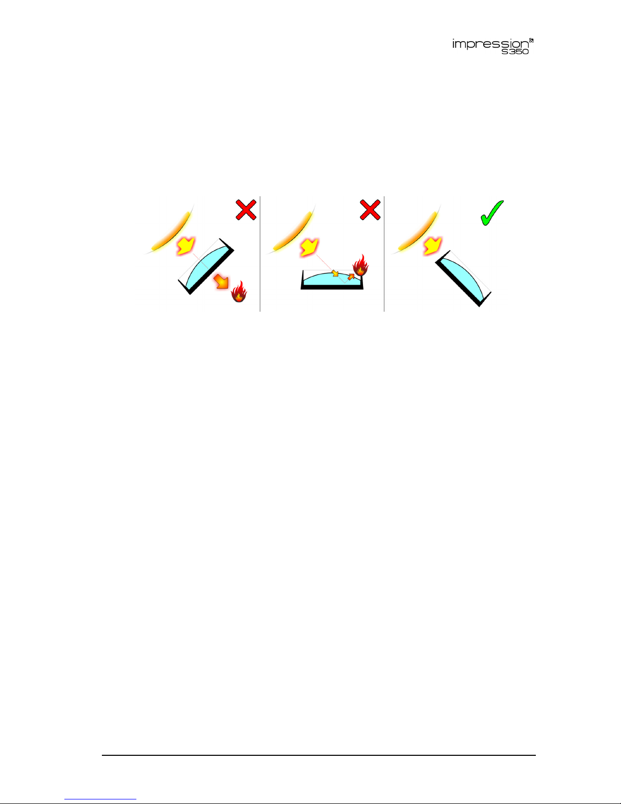
2. Avoiding damage
Do not point the front of the fixture towards the sun or other strong light sources. The
front lens focuses and concentrates light just like a magnifying glass. Strong light can
cause internal damage to the fixture, melting components or starting an internal fire
within seconds.
Figure 1. Avoiding damage from light sources
Damage can occur whether the fixture is powered on or off. See Figure 1. Damage
can also occur if the light hits the front of the fixture at an angle: the fixture does not
need to be pointing directly at the sun or other light source.
To avoid problems from strong light sources:
• Do not expose the front of a fixture to sunlight or any other strong light source.
• For outdoor applications during daylight, make sure that the front face of any fixture is
shielded or points away from the sun, even when not in use.
• Avoid pointing other high-powered beam lights directly at the fixture.
Do not pick up or carry the fixture by the front lens bezel, as it is not designed to
support the weight of the fixture. The LCD display is also fragile. Picking up or
supporting the fixture in these places could result in damage that is not covered by the
warranty.
Use only original spare parts. Any structural modification of the system will void the
product warranty.
Protect the front lens from dirt, dust and other contaminants. Do not touch the front
lens. Airborne particles and grease from your fingers can become baked onto the lens
and difficult to remove.
Clean optical components only as directed in this manual (see ‘Caring for your
product’ on page 36). Oils, solvents, and other chemicals commonly used for cleaning
can damage the lens coatings and surfaces.
Do not drop the product or expose it to mechanical stress.
Do not expose the product to heat (from other lighting fixtures for example).
Page 10

www.glp.de
10 GLP® impression S350
User Manual Rev. A
Transportation and storage
Transport the impression S350 either in a flightcase or in its original packaging to
protect the fixture from damage caused by shocks during transportation.
Store the fixture in a dry location where the temperature will remain above 0° C (32° F)
when not in use.
Important! Allow the fixture to cool completely and release the tilt lock before packing
or transporting the fixture in a flightcase or the original cardboard box.
Page 11
German Light Products®
GLP® impression S350 User Manual 11
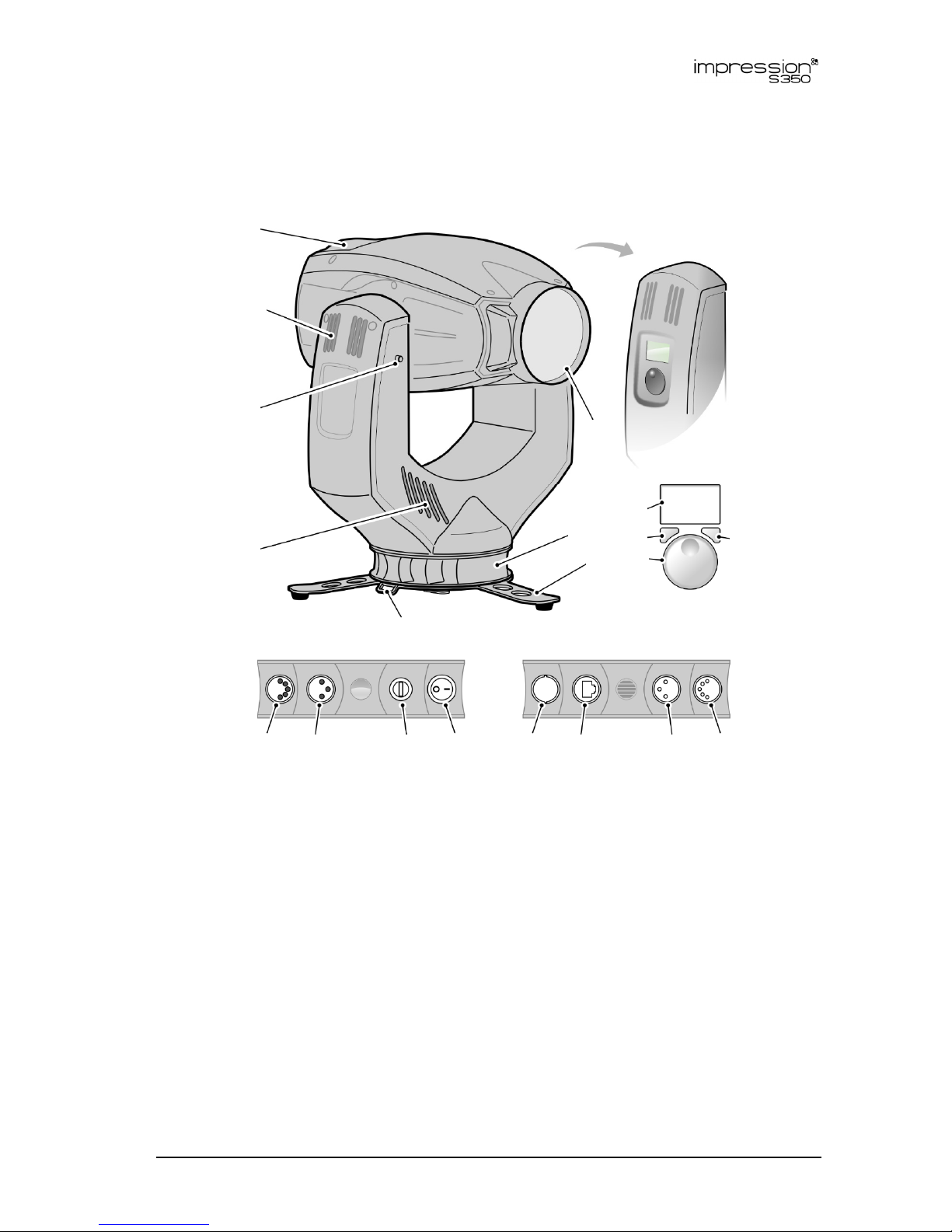
3. Product overview
Figure 2: Product overview
A – Head
B – Front glass
C – Mini-base with safety cable
attachment points
D – Tripod stand (supplied)
E – Stabilizing strap attachment point
F – Yoke cooling vents
G – Tilt lock
H – Yoke cooling vents
I – Control panel display
J – Mode button
K – Jog wheel
L – Enter button
M – DMX Out (thru) 5-pin XLR
N – DMX Out (thru) 3-pin XLR
O – Fuseholder
P – Power On/Off
Q – AC mains power In
R – Ethernet Port
S – DMX In 3-pin XLR
T – DMX In 5-pin XLR
A
B
C
D
E
F
G
J
K
L
M
N
O P
Q
R
S
T
Page 12

www.glp.de
12 GLP® impression S350
User Manual Rev. A
4. Product features
The impression S350 from GLP is a high-quality moving head lighting fixture with a 350W
white light LED engine that provides outstanding color rendering and rich, natural
colors. Advanced German design allows exceptional performance and a versatile
feature set to be packed into one of the most compact moving head lighting fixtures
currently available, using GLP’s familiar ‘baseless’ format.
Rotating gobos, fixed gobos and a gobo animation wheel give impressive projections
and beam effects. A rotating 8-facet prism and a flexible four-blade rotating framing
module add to the impression 350’s packed feature set. Precisely engineered optics
give a powerful, homogenous and sharply defined beam throughout the fixture’s
zoom range. Power input via a Neutrik powerCON TRUE1 connector allows hot
plugging.
The impression S350 is designed for permanent or temporary indoor use. It can be used
outdoors if it is protected from moisture and precautions are taken to prevent damage
from direct sunlight. It may be placed upright on a level surface or suspended from a
suitable structure as described this manual.
The impression S350 is not suitable for household use, for use in any location where
unattended children have access to it, or for use in permanent outdoor installations.
Light source
The impression S350 is equipped with a 350 W white light LED engine with a rated
lifetime of 20 000 hours to >70% LED output.
Control panel
The control panel on the side of the yoke has a backlit graphic LCD display for setting
up the fixture and changing fixture settings. See ‘Control menu layout’ on page 25 for
a table showing the control menu structure and options available.
Pan and tilt
The impression S350 pans through 640° and tilts through 262°, with coarse and fine
control channels and self-correcting position feedback available.
Pan and tilt position feedback can be disabled/enabled using the control panel or the
Special / Control DMX channel.
The direction of pan and/or tilt movement can be reversed by selecting an Invert
command using the fixture’s control panel or the Special / Control DMX channel.
Inverting movement is a fast way of obtaining symmetrical effects without
reprogramming at the console.
Page 13
German Light Products®
GLP® impression S350 User Manual 13
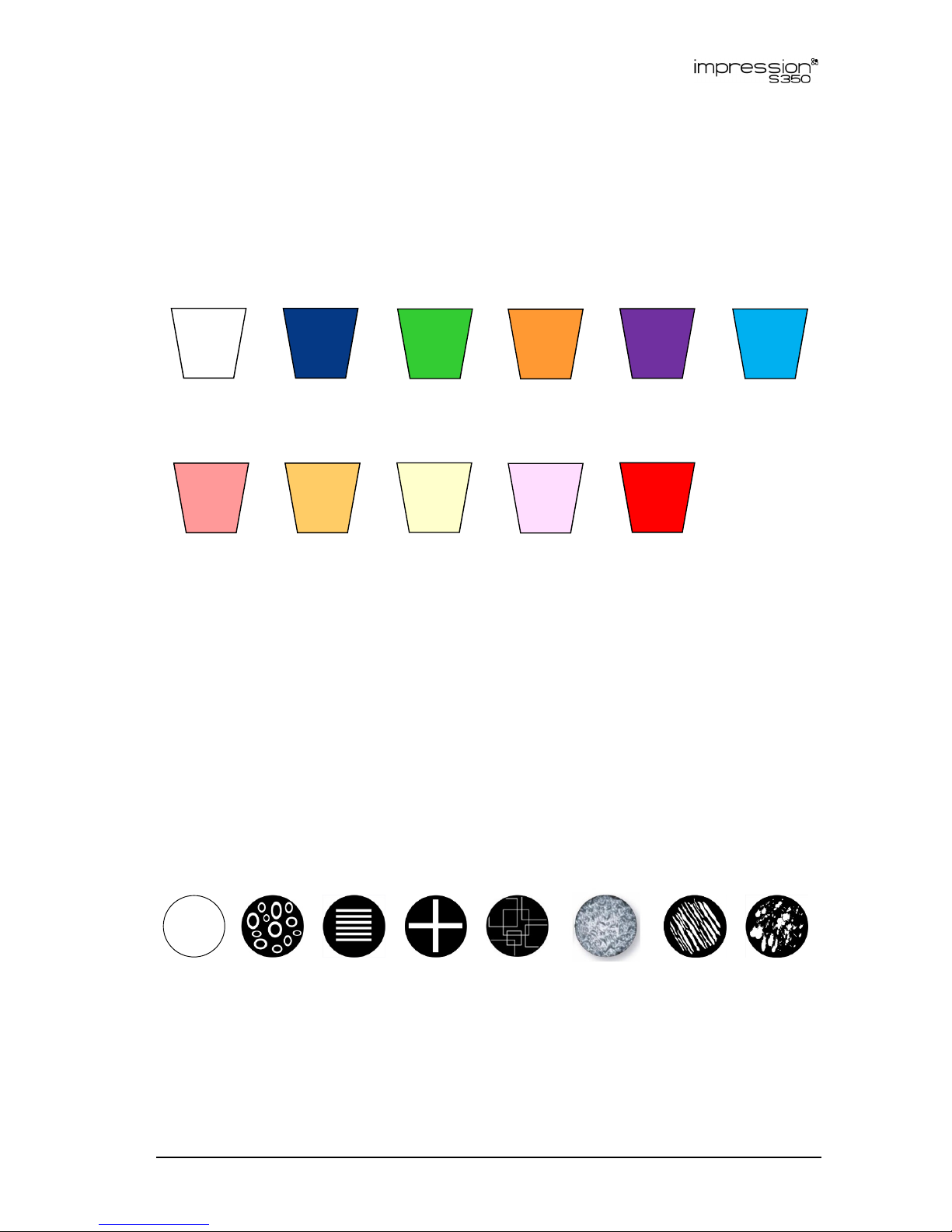
Color
The impression S350 provides 0-100% continuous CMY color mixing and a 10-slot color
wheel with ten dichroic color filters including CTC (see Figure 3).
A good method of controlling color is to set CMY levels to 0% when you begin to use
the color wheel. Then, after you have selected a color on the color wheel, you can
fine tune it using the CMY channels.
Open Slot 1
Congo Blue
(UV)
Slot 2
Green
Slot 3
Orange
Slot 4
Magenta
Slot 5
Blue
Slot 6
CTC 1
Slot 7
CTC 2
Slot 8
CTC 3
Slot 9
Minus green
Slot 10
Red
Figure 3. Color wheel
CTC
The CTC DMX channel lets you adjust color temperature from 8 000 K to 2500 K by
deploying the CMY flags. The channel sets the flags into the perfect positions for
matching color temperatures on the black body line.
A recommended approach is to set CMY levels to 0% when you begin to use the CTC
channel. After you have selected a color temperature on the CTC channel you can
fine tune it using the CMY channel.
Rotating gobos
The rotating gobo wheel contains the seven rotating gobos shown below:
Open Gobo 1
Crazy
Loops
Gobo 2
Block of
Lines
Gobo 3
Crossed
Lines
Gobo 4
Zigzag
Gobo 5
Ornament
Gobo 6
Zebra
Gobo 7
Bad
Painter
Figure 4. Rotating gobos
You can either select a rotating gobo or set the entire gobo wheel to rotate with
variable speed and direction on DMX channel 10. Then you can either set gobo
Page 14
www.glp.de
14 GLP® impression S350
User Manual Rev. A
indexed angle or set gobo rotation speed and direction with 16-bit control on
channels 11 and 12.
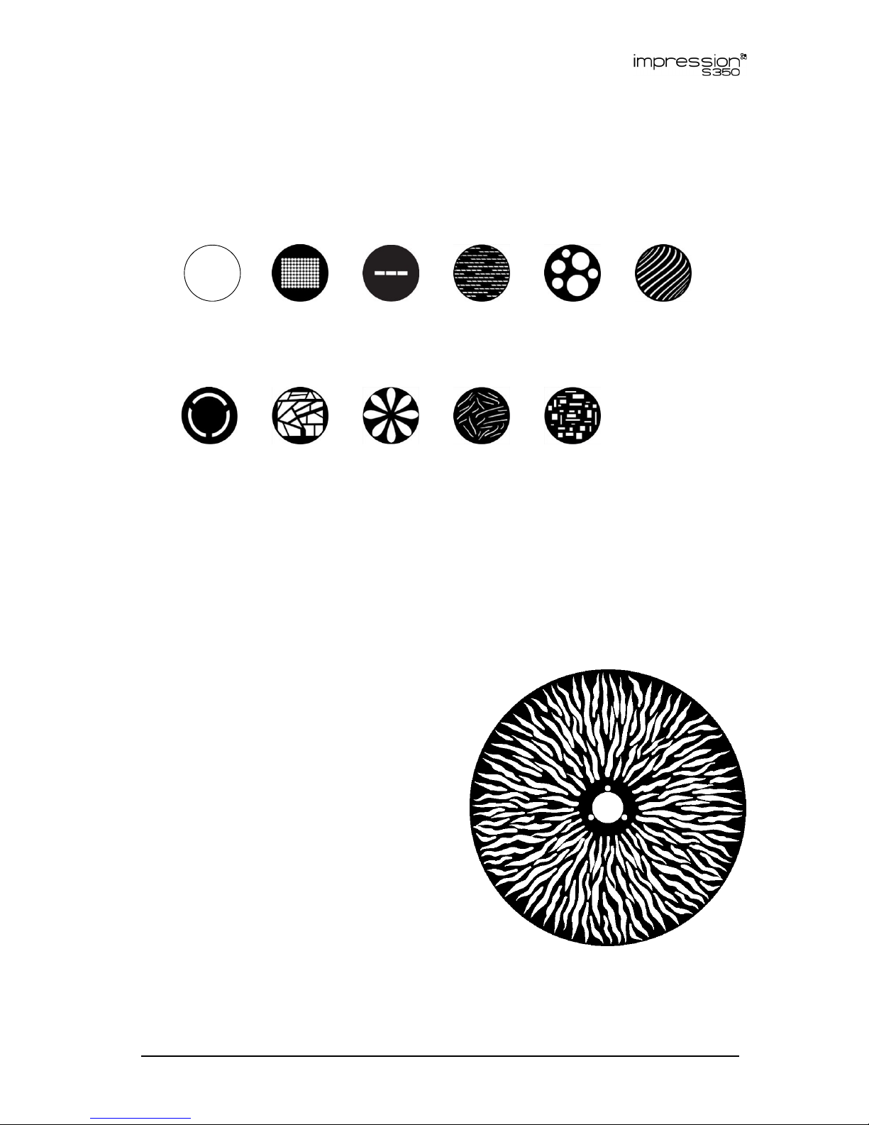
Fixed gobos
The fixed gobo wheel contains the ten fixed gobos shown below:
Open Gobo 1
Dots in
Square
Gobo 2
Three
Thirds Line
Gobo 3
Ants
Gobo 4
Big Dots
Gobo 5
Wave
Lines
Gobo 6
Three
Thirds
Circle
Gobo 7
Mosaic
Window
Gobo 8
Daisy
Flower
Gobo 9
Hairy
Gobo 10
Random
Blocks
Figure 5. Fixed gobos
You can either select a fixed gobo or set the entire fixed gobo wheel to rotate with
variable speed and direction on DMX channel 13.
Animation wheel
You can deploy the animation wheel with
the animation profile at continuously
variable angles from 0° to 90° to give
horizontal, diagonal or vertical animation
effects. You can also vary the speed and
direction of the animation wheel rotation.
When used in combination with static or
varying colors, rotating or fixed gobos,
framing and frost or focus, the animation
wheel makes a huge range of effects
possible, from abstract moving patterns to
simulated flames, branches in the wind,
ripples on water, etc.
Figure 6. Animation wheel
Page 15

German Light Products®
GLP® impression S350 User Manual 15
Framing
The four-blade framing module offers individual control of each blade, and the entire
module can be indexed continuously from -45° to +45°. Blades can be continuously
angled by +/- 30° and inserted by up to 100%, giving flexibility in choice of frame shape
and size right down to dead blackout.
Two framing control modes are available:
• PI (Position/Indexing) mode lets you insert each blade into the beam from 0% to 100%
on one channel and tilt each blade from -30° to + 30° on the next channel. Inserting
all four blades 100% into the beam will result in dead blackout. The fixture is set to PI
mode by default.
• LR (Left/Right) mode gives you individual control of the left-hand and the right-hand
sides of each of the four blades. In this mode, for example, DMX channel 25 gives
control of the left-hand side of blade 1 and channel 26 gives control of the right-hand
side of blade 1.
To use framing, select either PI mode (this mode is selected by default) or LR mode
using either the fixture’s control panel or the Special / Control DMX channel. Then use
DMX channels 25 – 32 to control the four framing blades and use DMX channel 24 to
set the indexed angle of the entire framing module.
Frost
The frost system offers two levels of frost effect that can give softer, more diffuse
projections: a continuously variable light frost and a continuously variable medium
frost.
Shutter effects
The impression S350 features an electronic dimmer / shutter system that provides pulse
and strobe effects as well as instant open and blackout.
Dimming
0 – 100% continuous dimming is available.
See Figure 7. You can select from two dimming curves using the control panel or the
Special / Control DMX channel: Linear and Extra soft:
• Light output using the Linear curve will appear to increase and decrease evenly
throughout the dimming range.
• The Extra soft curve gives finer control at low light levels (where the eye is more
sensitive to changes in light level) and coarser control at high levels.
The default setting is Extra soft.
Page 16

www.glp.de
16 GLP® impression S350
User Manual Rev. A
Light
output
DMX control value
Figure 7. Dimming curves
Zoom
The impression S350 has a 1:5 zoom range. You can narrow the beam angle from 42°
to 8°.
Control on the Zoom DMX channel can be inverted. Normal control as the DMX value
increases is flood
spot. You can invert this using the control panel and the Special /
Control DMX channel so that control becomes spot
flood.
Focus and focus tracking
You can carry out 8-bit focus adjustment on DMX channel 17 and fine 16-bit
adjustment on DMX channel 18.
You can also set focus to automatically adjust to match different zoom angles if you
enable focus tracking in the fixture’s control panel or on the Special / Control DMX
channel. This feature is useful when zooming in mid-air effects.
Focus tracking can be optimized for three different projection distance ranges. Four
focus tracking settings are available:
• Focus tracking OFF sets the zoom and focus DMX channels to control zoom and focus
completely independently of each other.
• Focus tracking NEAR sets focus to automatically adjust for optimum sharpness at
projection distances of around 10 meters or less when the zoom angle is changed.
• Focus tracking MEDIUM sets focus to automatically adjust for optimum sharpness at
projection distances of around 11 - 20 meters when the zoom angle is changed.
• Focus tracking FAR sets focus to automatically adjust for optimum sharpness at
projection distances of over 20 meters when the zoom angle is changed.
If you have enabled Focus tracking NEAR, MEDIUM or FAR you can still override the
automatic focus setting: any manual adjustment that you make on the Focus DMX
channel will take priority over the automatic setting. However, if you change the zoom
angle again, the fixture will forget any manual focus setting and return to
automatically adjusting focus to match the fixture’s zoom angle.
Page 17

German Light Products®
GLP® impression S350 User Manual 17
Fan modes
The four different cooling fan modes give you a range of options to choose from
depending on how you want to allocate priority between high-intensity light output or
low fan noise:
• Fan regulated gives priority to light output and only operates fans as necessary. If the
fixture is blacked out, fans run at minimum speed. When light output intensity is
increased, temperature regulation increases fan speed to the level necessary to keep
the fixture at optimum temperature.
If light output is set to maximum intensity but the fans can keep the fixture at optimum
temperature, there will be no regulation of light intensity. If the fixture begins to
exceed optimum temperature, light intensity will be limited until optimum
temperature can be maintained.
• Fan constant high mode is optimized for maximum light output and suits operation in
high ambient temperatures. Fans are set to constant operation at high speed. Light
output intensity is limited smoothly if it becomes necessary in order to keep fixture
temperature at optimum level.
Besides maximizing light output in high ambient temperatures, you can use this mode
to cool down a fixture quickly or to remove dust from cooling fans.
• Fan constant medium sets fans to constant operation at medium speed. Light output
intensity is reduced to a level where it will normally remain constant at ambient
temperatures of up to 45° C (113° F). Intensity is smoothly limited further if it becomes
necessary in order to keep fixture temperature at optimum level.
• Fan constant low mode sets fans to constant operation at low speed and is optimized
for minimum noise. Light output intensity is reduced to a level where it will normally
remain constant at ambient temperatures of up to 30° C (86° F). Intensity is smoothly
limited further if it becomes necessary in order to keep fixture temperature at
optimum level.
In all fan modes, if fixture temperature reaches a dangerous level, LEDs will be shut
down for a period until the fans have brought the temperature down to a safe level.
You can set the cooling fan mode using the control panel or the Special / Control DMX
channel.
Effect wheel shortcuts
By default, the color wheel and gobo wheels take the shortest, fastest route from one
slot to the next, even if this means that they may pass through the open position. To
avoid the wheels passing through the open position when they change from one slot
to the next you can set Effect shortcuts on the Special / Control DMX channel to OFF.
Behavior when the fixture is not receiving a DMX signal
You can set the fixture to react in four different ways if no DMX signal is present (if the
fixture is being controlled by DMX but the DMX signal stops, or if you apply power to
the fixture when no DMX signal is present):
• Hold sets the fixture to continue obeying the last DMX values it received. This is the
default setting.
• Blackout sets the fixture to black out whenever it is not receiving a DMX signal.
Page 18

www.glp.de
18 GLP® impression S350
User Manual Rev. A
• Stand-Alone sets the fixture to play its stored stand-alone scene (see DMX Shot below)
when the fixture is not receiving a DMX signal. If no stand-alone scene is stored in
memory, the fixture will black out.
• DMX Shot takes a snapshot of the DMX values that are currently being received and
stores them in the fixture’s memory as its stand-alone scene. The fixture will display this
stand-alone scene if it is set to Stand-Alone (see above) and is not receiving a DMX
signal.
You can select one of the four settings above using either the control panel or the
Special / Control DMX channel.
Stand-Alone operation
If the fixture is set to Stand-Alone and if a stand-alone scene has been stored in its
memory using the DMX Shot command, it will display its stand-alone scene at all times
when it is powered on but not receiving a DMX signal. You can therefore use this
setting if you want fixtures to automatically start stand-alone operation when you
apply power to them.
PWM frequency
You can change the LED dimming PWM frequency in order to avoid flicker and beat
frequencies in video images. To do this, select a new PWM frequency using either the
Settings DMX channel or the fixture’s control panel.
The default PWM setting is 3000 Hz. You can set the PWM frequency to 2200 Hz,
3000 Hz, 4800 Hz, 9600 Hz or 25 kHz. Note that a higher PWM frequency may affect
dimming performance.
The PWM frequency setting is stored in the fixture and is not affected by cycling power
off and on. However, it will be affected if you use the Factory default command in the
control menus.
As a rule, you should set all the fixtures in an installation to the same PWM frequency in
order to ensure the same performance.
Installation options
The base has four Camlock fastener points and two M10 threaded holes for a
removable tripod (supplied), omega brackets or direct mounting of half-coupler
clamps, allowing various rigging options.
Two eyelets are provided for safety cable attachment.
Page 19

German Light Products®
GLP® impression S350 User Manual 19
Figure 8 Mounting points in base
5. Preparation for use
Warning! Read ‘Safety’ starting on page 4 for important safety information
that you must understand before you install or operate the fixture.
Included Items
The impression S350 is supplied with a power cable with a powerCON TRUE1 connector
and a tripod with Camlock fasteners for use as a floor stand.
Orientation and location
The impression S350 may be rigged in any orientation following the instructions in this
chapter or placed on a level surface in locations where it is safe to stand the fixture.
Keep the head at least 0.2 m (8 in.) away from combustible materials (including
curtains and stage scenery) when the fixture is installed.
Make sure that there is no risk of collision when the head pans and tilts. Allow a
minimum center-to-center distance of 600 mm (23.6 in.) when installing impression S350
fixtures side by side.
Mounting fasteners in base
See Figure 8. The base of the impression S350 has two threaded holes A that accept
M10 bolts or screws, and four mounting points B that accept standard camlock
quarter-turn fasteners. The camlock center-to-center distance is 90 mm (3.54 in.).
A
B
B
B
B
A
Page 20

www.glp.de
20 GLP® impression S350
User Manual Rev. A
Mounting with rigging clamps
To install the impression S350 in any orientation on a rigging
truss or similar support:
See Figure 9. Pass two M10 grade 8.8 steel bolts or
screws through two half-coupler type rigging clamps
and check that the bolts will protrude minimum 9 mm /
0.35 in. and maximum 11 mm / 0.43 in. into the base of
the fixture when tightened.
See Figure 8. Fasten the bolts through the half-coupler
clamps and into holes A in the base of the fixture so
that the clamps are held securely.
Fasten the rigging clamps securely around a chord on a rigging truss or similar bar.
Secure the fixture with a safety cable as described in ‘Safety attachment’ on page
20.
Make sure that the head will not collide with another fixture or any other object
when it moves through its full pan and tilt ranges.
Safety attachment
If the impression S350 may cause
injury or damage if it falls, you
must secure it with a secondary
attachment such as a safety
cable. To install a safety cable:
Obtain a safety cable that is
approved for the load it will
secure.
See Figure 10. Fasten the
safety cable to one of the
safety cable attachment
points in the base of the
fixture and loop it around a
secure anchoring point such
as a truss chord. Remove as
much slack as possible in the safety cable (by looping it more than once around
the truss chord, for example).
Secure the safety cable and check that it will hold the fixture if a primary
attachment fails.
Figure 9. Min./max. bolt
protrusion into base
(millimeters)
Figure 10. Safety cable attachment points in base of
fixture
Page 21

German Light Products®
GLP® impression S350 User Manual 21
Placing on a surface
If you install the supplied tripod on the base of the fixture, you can stand the impression
S350 upright on a flat, stable, horizontal surface in any location where the fixture is not
accessible to the public and will not present any safety risks.
If necessary to prevent the fixture from moving or
falling, pass a ratchet strap, webbing or other suitable
bracing strap through the safety cable attachment
points in the base (see Figure 10) or the strap
attachment points in the tripod stand (see Figure 11)
and fasten it to secure anchoring points. Make sure
that the strap is tight enough to hold the fixture, but do
not distort attachment points by overtightening the
strap.
If the fixture may cause injury or damage if it falls,
secure it with a safety cable as described in ‘Safety
attachment’ on page 20.
Make sure that the head will not collide with anything
when it tilts and rotates.
Connecting to power
The AC mains power supply must include a connection to ground / protective earth. It
must be protected against ground / earth leakage and overload. The auto-sensing
power supply accepts AC power at 100-240 V, 50/60 Hz. Do not connect the fixture to
power at any other voltage or to an external dimmer.
The impression S350 has a 3-conductor Neutrik powerCON TRUE1 socket that accepts
AC power from a Neutrik powerCON TRUE1 female cable connector.
Although powerCON TRUE1 connectors support hot-plugging, it is still good practice to
shut down power to power cables or move Power ON/OFF switches to OFF before
connecting power cables to fixtures.
To connect the fixture to power:
Check that power to the power input cable is shut down or that the fixture’s power
switch is set to OFF.
See Q in Figure 2 on page 11. Note the position of the keys and keyways on the
power cable connector and Mains In socket and align them with each other. Insert
the cable connector into the socket and twist clockwise to lock.
Before applying power by energizing the power cable and/or switching on the
power switch, check that the head is unlocked and can move freely and check
that nobody is looking directly into the front of the fixture.
Installing power connectors
It is possible to install a cord cap / mains power plug that is suitable for your local
convenience receptacles / power sockets on the supplied power input cable. If you
do this, check that the cord cap / plug is rated minimum 250 V, 16 A, that it has a
connection to ground / earth and that it has an integral cable grip. Follow the cord
cap / plug manufacturer’s assembly instructions.
Figure 11. Strap attachment
points in tripod stand
Page 22

www.glp.de
22 GLP® impression S350
User Manual Rev. A
If you need to install a Neutrik powerCON TRUE1 connector on a power cable, follow
the instructions given in the Support area of the Neutrik website at www.neutrik.com.
Respect the color coding used in the supplied power cable and in your local mains
power wiring system. US and EU systems use the color coding shown below:
Live or L Neutral or N
Ground / Earth or
US system Black White Green
EU system Brown Blue Yellow/green
Main fuse
See Figure 12. The main fuse sits in a holder in the
base.
If the fixture appears to be completely shut down
even though power is applied, the main fuse may
have blown. Disconnect the fixture from power
before replacing the fuse. You can open the
fuseholder with a flat-headed screwdriver. Replace
only with a fuse of the same type and rating.
If the fuse blows repeatedly, disconnect the fixture
from power and contact GLP for service and
repair.
Connecting to a DMX control data link
The impression S350 provides 5-pin and 3-pin XLR IN and THRU sockets for connection to
a USITT DMX512 data link.
Connectors use standard DMX pinout:
• Pin 1 = Ground
• Pin 2 = Negative / data cold
• Pin 3 = Positive / data hot.
• Pins 4 and 5 are not used.
If you would like any advice with planning and installing a DMX link, your GLP supplier
will be happy to provide assistance.
Figure 12. Main fuse
Page 23

German Light Products®
GLP® impression S350 User Manual 23
Figure 13. Control panel
6. Control menus and LCD display
Warning! DMX control is disabled when the control menus are active. Be
prepared for the head to move as soon as you exit the control menus.
The control panel and LCD display provide access to user settings, readouts, and
utilities.
When power is applied, the fixture resets and impression S350 appears in the display
panel. After the reset has completed, the main menu is displayed:
V:0.12/NE 3000
101
-135
Next
136
DMX Start Address
Mode Enter
See Figure 13. From left to right, the top line of the main menu displays:
• Main CPU software version
• Pan, tilt, and zoom modes: N (Normal) or I (inverse)
• Dimming curve: L (Linear) or E (Extra Soft)
• PWM frequency.
Page 24

www.glp.de
24 GLP® impression S350
User Manual Rev. A
In the example shown in Figure 13:
• The fixture is running CPU software version 0.12
• Pan, Tilt and Zoom are Normal
• Dimming is Extra-soft
• The current PWM frequency is 3000 Hz
• The fixture’s DMX start address is 101, it uses DMX channels 101 – 135, and DMX
channel 136 is available for use as the start address of the next device on the DMX
link.
A flashing display indicates loss of DMX.
To use the control panel:
• Use the Jog wheel to scroll up and down through menu options.
• Press the Enter button to select a setting, confirm a command or enter a submenu.
• Press the Mode button to escape and return to the top of the menu.
Page 25

German Light Products®
GLP® impression S350 User Manual 25
7. Control menu layout
DMX Start
Address
1 - 512 Set DMX start address
Special
Set Dimming
Mode
Esoft
Select dimming curve:
Extra Soft / Linear
Lin
Show Errors Execute
Display any stored
errors
Framing
Mode
PI
Set framing control
mode to Position /
Indexed angle
LR
Set framing control
mode to Left / Right
No DMX
Blackout
Fixture blacks out if
DMX signal stops
Hold
Fixture continues to
display current effect
if DMX signal stops
Stand-Alone
Fixture displays its
stand-alone scene if
DMX signal stops
DMX Shot
Fixture stores the
scene it is currently
displaying as its standalone scene
Set PWM
Frequency
2200 Hz
Set PWM frequency
3000 Hz
4800 Hz
9600 Hz
25 000 Hz
Focus
Tracking
Mode
OFF
Set zoom / focus
tracking distance
Near
Medium
Far
Shortcut
ON
Effect wheel shortcuts
(pass through open)
OFF
Page 26

www.glp.de
26 GLP® impression S350
User Manual Rev. A
Special
(contd.)
Set Fan
Mode
Regulated (REG)
Fan speed
temperatureregulated
Low
Fan speed constant:
low / medium / high
Medium
High
Set Display
Mode
Normal (NORM)
Onboard display
panel sleeps after 30
seconds
ON
Onboard display
panel constantly on
OFF
Onboard display
panel constantly off
Default Execute
Return fixture to
factory default
settings
Temperature
LED
XXX° LED PCB temperature
Temperature
main
XXX°
Main PCB
temperature
Temperature
base
XXX° Base PCB temperature
Boot count XXX
Number of startups
since manufacture
(non-resettable)
Fixture hours XXX
Operating hours since
manufacture (non-
resettable)
Version Infos
Main
Fixture firmware
version
Artnet/WDMX
Art-Net / WDMX driver
version
LED Driver
Driver versions
Framing Driver 1
Framing Driver 2
Color Driver
Head Driver
Effect Driver
Pan Driver
Tilt Driver
Main Fan Driver
LED Fan Driver
Color Fan Driver
Page 27

German Light Products®
GLP® impression S350 User Manual 27
Special
(continued)
Adjust
Key code
Enter
value
Pan Offset
Set adjustment offset
values
Tilt Offset
Zoom Offset
Focus Offset
Prism Position
offs.
Frost offset
RotGob Pos.
Offset
RotGob Pos.
Compens
RotGob Rot.
Offset
EffectWhl Pos.
Offs.
FixGobo offset
ColorWheel
offset
Cyan Offset
Cyan Offset fine
Magenta Offset
Magenta Offset
fine
Yellow Offset
Yellow Offset
fine
Framing Blade
1a
Framing Blade
1b
Framing Blade
2a
Framing Blade
2b
Framing Blade
3a
Framing Blade
3b
Framing Blade
4a
Framing Blade
4b
Framing
Rotation
Page 28

www.glp.de
28 GLP® impression S350
User Manual Rev. A
Display Flip ON / OFF Invert onboard display
Position
Feedback
ON / OFF
Enable/Disable Pan/Tilt
position feedback
Reverse Pan ON / OFF Invert Pan
Reverse Tilt ON / OFF Invert Tilt
Reverse
Zoom
ON / OFF
Invert Zoom
from Wide Spot
to Spot Wide
Reset
Pan/Tilt only
ON / OFF Reset Pan and Tilt
Reset head
only
ON / OFF
Reset effects and
processes in head
Reset ON / OFF Reset entire fixture
Default values are shown in bold type.
User-settable values are displayed in grey boxes.
Page 29

German Light Products®
GLP® impression S350 User Manual 29
8. DMX channel layout
Normal mode (35 DMX channels)
Channel Function Description
DMX
range
Default
DMX
% Range Fade
1
Pan coarse
Left – right in 1.2°
increments (16 bit)
0 – 65535 32767 0 – 100% Fade
2
Pan fine
3
Tilt coarse
Up – down in 1.2° increments
(16 bit)
0 – 65535 32767 0 – 100% Fade
4
Tilt fine
5
Color wheel Open – White 6000 K
Color 01 – Congo blue (UV)
Color 02 – Green
Color 03 – Orange
Color 04 – Magenta
Color 05 – Blue
Color 06 – CTC 1
Color 07 – CTC 2
Color 08 – CTC 3
Color 09 – Minus green
Color 10 – Red
Color wheel indexing 0 – 360°
(continuous color changing)
Color wheel rotation CW
fast – slow
Color wheel rotation stop
Color wheel rotation CCW
slow – fast
0 – 3
4 – 7
8 – 11
12 – 15
16 – 19
20 – 23
24 – 27
28 – 31
32 – 35
36 – 39
40 – 43
44 – 167
168 – 211
212
213 – 255
0 0 – 1.2%
1.6 – 2.7%
3.1 – 4.3%
4.7 – 5.9%
6.3 – 7.5%
7.8 – 9.0%
9.4 – 10.6%
11.0 – 12.2%
12.5 – 13.7%
14.1 – 15.3%
15.7 – 16.9%
17.3 – 65.5%
65.9 – 82.7%
83.1%
83.5 – 100%
Snap
Snap
Snap
Snap
Snap
Snap
Snap
Snap
Snap
Snap
Snap
Fade
Fade
Snap
Fade
6
Cyan Cyan 0 – 100% 0 – 255
0
0 – 100% Fade
7
Magenta Magenta 0 – 100% 0 – 255
0
0 – 100% Fade
8
Yellow Yellow 0 – 100% 0 – 255
0
0 – 100% Fade
9
CTC Off (default: 6000 K)
8000 K
7900 K
7800 K
7700 K
7600 K
7500 K
7400 K
7300 K
7200 K
7100 K
7000 K
6900 K
6800 K
6700 K
6600 K
6500 K
6400 K
6300 K
6200 K
6100 K
6000 K
5900 K
0 – 31
32 – 35
36 – 39
40 – 43
44 – 47
48 – 51
52 – 55
56 – 59
60 – 63
64 – 67
68 – 71
72 – 75
76 – 79
80 – 83
84 – 87
88 – 91
92 – 95
96 – 99
100 – 103
104 – 107
108 – 111
112 – 115
116 – 119
0 0 – 12.2%
12.5 – 13.7%
14.1 – 15.3%
15.7 – 16.9%
17.3 – 18.4%
18.8 – 20.0%
20.4 – 21.6%
22.0 – 23.1%
23.5 – 24.7%
25.1 – 26.3%
26.7 – 27.8%
28.2 – 29.4%
29.8 – 31.0%
31.4 – 32.5%
32.9 – 34.1%
34.5 – 35.7%
36.1 – 37.3%
37.6 – 38.8%
39.2 – 40.4%
40.8 – 42.0%
42.4 – 43.5%
43.9 – 45.1%
45.5 – 46.7%
Snap
Fade
Page 30

www.glp.de
30 GLP® impression S350
User Manual Rev. A
9
continued
5800 K
5700 K
5600 K
5500 K
5400 K
5300 K
5200 K
5100 K
5000 K
4900 K
4800 K
4700 K
4600 K
4500 K
4400 K
4300 K
4200 K
4100 K
4000 K
3900 K
3800 K
3700 K
3600 K
3500 K
3400 K
3300 K
3200 K
3100 K
3000 K
2900 K
2800 K
2700 K
2600 K
2500 K
120 – 123
124 – 127
128 – 131
132 – 135
136 – 139
140 – 143
144 – 147
148 – 151
152 – 155
156 – 159
160 – 163
164 – 167
168 – 171
172 – 175
176 – 179
180 – 183
184 – 187
188 – 191
192 – 195
196 – 199
200 – 203
204 – 207
208 – 211
212 – 215
216 – 219
220 – 223
224 – 227
228 – 231
232 – 235
236 – 239
240 – 243
244 – 247
248 – 251
252 – 255
47.1 – 48.2%
48.6 – 49.8%
50.2 – 51.4%
51.8 – 52.9%
53.3 – 54.5%
54.9 – 56.1%
56.5 – 57.6%
58.0 – 59.2%
59.6 – 60.8%
61.2 – 62.4%
62.7 – 63.9%
64.3 – 65.5%
65.9 – 67.1%
67.5 – 68.6%
69,0 – 70.2%
70.6 – 71.8%
72.2 – 73.3%
73.7 – 74.9%
75.3 – 76.5%
76.9 – 78.0%
78.4 – 79.6%
80.0 – 81.2%
81.6 – 82.7%
83.1 – 84.3%
84.7 – 85.9%
86.3 – 87.5%
87.8 – 89.0%
89.4 – 90.6%
91.0 – 92.2%
92.5 – 93.7%
94.1 – 95.3%
95.7 – 96.9%
97.3 – 98.4%
98.8 – 100%
Fade
10
Gobo wheel 1
gobo selection
Open 0 – 15 0 0 – 5.9% Snap
Gobo 01
16 – 31 6.3 – 12.2%
Gobo 02
32 – 47 12.5 – 18.4%
Gobo 03
48 – 63 18.8 – 24.7%
Page 31

German Light Products®
GLP® impression S350 User Manual 31
10
continued
Gobo 04 64 – 79
25.1 – 31% Snap
Gobo 05
80 – 95 31.4 – 37.3%
Gobo 06
96 – 111 37.6 – 43.5%
Gobo 07
112 – 127 43.9 – 49.8%
Gobo wheel rotation stop 128 50.2%
Gobo wheel rotation CW
fast – slow
129 – 191
50.6 – 74.9% Fade
Gobo wheel rotation stop 192 75.3% Snap
Gobo wheel rotation CCW
slow – fast
193 – 255
75.7 – 100% Fade
11
Gobo wheel 1
index & rotation
Gobo index 0 – 360° 0 – 32767 0 0 – 50.0% Fade
Gobo rotation CW
fast – slow
32768 – 49151
50.0 – 74.9% Fade
12
Gobo rotation stop 49152 75% Snap
Gobo rotation CCW
slow – fast
49153 – 65535
75.1 – 100% Fade
13
Gobo wheel 2
(fixed gobos)
gobo selection
Open 0 – 7 0 0 – 2.7% Snap
Gobo 01
8 –15 3.1 – 5.9%
Gobo 02
16 – 23 6.3 – 9.0%
Gobo 03
24 – 31 9.4 – 12.2%
Gobo 04
32 – 39 12.5 – 15.3%
Page 32

www.glp.de
32 GLP® impression S350
User Manual Rev. A
13
continued
Gobo 05
40 – 47 15.7 – 18.4% Snap
Gobo 06
48 – 55 18.8 – 21.6%
Gobo 07
56 – 63 22.0 – 24.7%
Gobo 08
64 – 71 25.1 – 27.8%
Gobo 09
72 – 79 28.2 – 31%
Gobo 10
80 – 87 31.4 – 34.1%
No function 88 – 127 34.5 – 49.8%
Gobo wheel rotation stop 128 50.2% Snap
Gobo wheel rotation CW fast
– slow
129 – 191
50.6 – 74.9% Fade
Gobo wheel rotation stop 192 75.3% Snap
Gobo wheel rotation CCW
slow – fast
193 – 255
75.7 – 100% Fade
14
Shutter Closed 0 – 15 255 0 – 5.9% Snap
Pulse, random, slow – fast 16 – 47 6.3 – 18.4% Fade
Ramp-up, random, slow –
fast
48 – 79
18.8 – 31%
Ramp-down, random, slow –
fast
80 – 111
31.4 – 43.5%
Ramp-up-down, random,
slow – fast
112 – 143
43.9 – 56.1%
Strobe with b/o pause 5 – 0.1
sec.
144 – 199
56.5 – 78.0%
Strobe 1 – 10 Hz 200 – 239 78.4 – 93.7%
Open 240 – 255 94.1 – 100% Snap
Page 33

German Light Products®
GLP® impression S350 User Manual 33
15
Dimmer coarse
Intensity 0 – 100% 0 – 65535 32768 0 – 100% Fade
16
Dimmer fine
17
Focus coarse
Near – far 0 – 65535 32768 0 – 100% Fade
18
Focus fine
19
Zoom
Wide – narrow
0 – 255 128 0 – 100% Fade
20
Frost No frost 0 – 3 0 0 – 1.2% Snap
Frost light 0 – 100% 4 – 127 1.6 – 49.8% Fade
Frost heavy 0 – 100% 128 – 255 50.2 – 100%
21
Prism No prism 0 – 7 0 0 – 2.7% Snap
Prism rotation CW fast - slow 8 – 130 3.1 – 51% Fade
Prism rotation stop 131 51.4% Snap
Prism rotation CCW
slow – fast
132 – 255
51.8 – 100% Fade
22
Effect wheel
position
Effect wheel out – in –
tilt 0 - 90°
0 – 255
0
0 – 100% Fade
23
Effect wheel
index/rotation
Effect wheel rotation stop 0 0 0% Snap
Effect wheel rotation CW
fast – slow
1 – 127
0.4 – 49.8% Fade
Effect wheel rotation stop 128 50.2% Snap
Effect wheel rotation CCW
slow – fast
129 – 255
50.6 – 100% Fade
24
Framing module
indexing
CW indexing from 0° to -45°
Center: 0°
CCW indexing from 0° to +45°
0 – 128
128
129 – 255
128 0 – 50.2%
50.2%
50.6 – 100%
Fade
Snap
Fade
25
Framing blade 1
position / left
PI mode: In – out
LR mode: Blade left side
0 – 255
0 – 255
0
0
0 – 100%
0 – 100%
Fade
Fade
26
Framing blade 1
index / right
PI mode: Tilt -30° – +30°
LR mode: Blade right side
0 – 255
0 – 255
128
0
0 – 100%
0 – 100%
Fade
Fade
27
Framing blade 2
position / left
PI mode: In – out
LR mode: Blade left side
0 – 255
0 – 255
0
0
0 – 100%
0 – 100%
Fade
Fade
28
Framing blade 2
index / right
PI mode: Tilt -30° – +30°
LR mode: Blade right side
0 – 255
0 – 255
128
0
0 – 100%
0 – 100%
Fade
Fade
29
Framing blade 3
position / left
PI mode: In – out
LR mode: Blade left side
0 – 255
0 – 255
0
0
0 – 100%
0 – 100%
Fade
Fade
30
Framing blade 3
index / right
PI mode: Tilt -30° – +30°
LR mode: Blade right side
0 – 255
0 – 255
128
0
0 – 100%
0 – 100%
Fade
Fade
31
Framing blade 4
position / left
PI mode: In – out
LR mode: Blade left side
0 – 255
0 – 255
0
0
0 – 100%
0 – 100%
Fade
Fade
32
Framing blade 4
index / right
PI mode: Tilt -30° – +30°
LR mode: Blade right side
0 – 255
0 – 255
128
0
0 – 100%
0 – 100%
Fade
Fade
Page 34

www.glp.de
34 GLP® impression S350
User Manual Rev. A
33
Special / Control No function
Dimmer curve extra soft*
Dimmer curve linear*
No function
Display off*
Display auto-off*
Display on*
Display orientation normal*
Display orientation invert*
No function
No DMX = blackout*
No DMX = hold*
No DMX = stand-alone*
No DMX = DMX shot*
No function
Fan regulated*
Fan high*
Fan medium*
Fan low*
No function
Position feedback off*
Position feedback on*
Effect shortcuts off*
Effect shortcuts on*
Tilt invert off*
Tilt invert on*
Pan invert off*
Pan invert on*
Zoom invert off*
Zoom invert on*
Focus tracking off*
Focus tracking near*
Focus tracking medium*
Focus tracking far*
No function
Framing Control = PI Mode,
(position/Index)*
Framing Control = LR Mode,
(left/right)*
No function
PWM 2200 Hz **
PWM 3000 Hz **
PWM 4800 Hz **
PWM 9600 Hz **
No function
PWM 25 kHz **
Set fixture to factory defaults**
No function
Reset pan/tilt *
Reset head*
Reset all*
0 – 38
39 – 41
42 – 44
45 – 53
54 – 56
57 – 59
60 – 62
63 – 65
66 – 68
69 – 71
72 – 74
75 – 77
78 – 80
81 – 83
84 – 86
87 – 89
90 – 92
93 – 95
96 – 98
99 – 104
105 – 107
108 – 110
111 – 113
114 – 116
117 – 119
120 – 122
123 – 125
126 – 128
129 – 131
132 – 134
141 – 143
144 – 146
147 – 149
150 – 152
153 – 158
159 – 161
162 – 164
165 – 191
192 – 194
195 – 197
198 – 200
201 – 203
204 – 206
207 – 209
240 – 242
243 – 245
246 – 248
249 – 251
252 – 255
0 0 – 14.9%
15.3 – 16.1%
16.5 – 17.3%
17.6 – 20.8%
21.2 – 22%
22.4 – 23.1%
23.5 – 24.3%
24.7 – 25.5%
25.9 – 26.7%
27.1 – 27.8%
28.2 – 29.0%
29.4 – 30.2%
30.6 – 31.4%
31.8 – 32.5%
32.9 – 33.7%
34.1 – 34.9%
35.3 – 36.1%
36.5 – 37.3%
37.6 – 38.4%
38.8 – 40.8%
41.2 – 42.0%
42.4 – 43.1%
43.5 – 44.3%
44.7 – 45.5%
45.9 – 46.7%
47.1 – 47.8%
48.2 – 49.0%
49.4 – 50.2%
50.6 – 51.4%
51.8 – 52.5%
55.3 – 56.1%
56.5 – 57.3%
57.6 – 58.4%
58.8 – 59.6%
60.0 – 62.0%
62.4 – 63.1%
63.5 – 64.3%
64.7 – 74.9%
75.3 – 76.1%
76.5 – 77.3%
77.6 – 78.4%
78.8 – 79.6%
80.0 – 80.8%
81.2 – 82.0%
94.1 – 94.9%
95.3 – 96.1%
96.5 – 97.3%
97.6 – 98.4%
98.8 – 100%
Snap
34
FX1 selection No FX
Chaser 1-2-3-4-3-2-1
Crossfade 1-2-3-4-3-2-1
Chaser 1+2 – 3+4
Crossfade 1+2 – 3+4
Chaser 1+4 – 2+3
Crossfade 1+4 – 2+3
Chaser random
Crossfade random
No function
0 – 10
11 – 14
15 – 18
19 – 22
23 – 26
27 – 30
31 – 34
35 – 38
39 – 42
43-255
0 0 – 3.9%
4.3 – 5.5%
5.9 – 7.1%
7.5 – 8.6%
9 – 10.2%
10.6 – 11.8%
12.2 – 13.3%
13.7 – 14.9%
15.3 – 16.5%
16.9 – 100%
Snap
Page 35

German Light Products®
GLP® impression S350 User Manual 35
35
FX1 adjustment FX1 speed slow – fast 0 – 255 0 0 – 100% Fade
* Move from zero and hold value for 3 seconds to apply
** Move from zero and hold value for 5 seconds to apply
Notes:
Percentage values are calculated by dividing DMX values by 2.56 and rounding to the
nearest 0.1%.
To apply a command on Channel 33 (Special / Control), start at a value of zero, then
move to the required value and hold it for the required time (e.g. 3 seconds). If you
move to the required value from any other value than zero, the command will not be
applied.
To adjust the PWM frequency using the Special / Control channel, start at a value of
zero, move to the required value and hold it for at least 5 seconds.
Default settings are written in bold type.
Page 36

www.glp.de
36 GLP® impression S350
User Manual Rev. A
9. Caring for your product
Cleaning
The buildup of dust, dirt and other airborne particles will reduce the fixture’s light
output. It will also prevent the fixture from cooling correctly, and this will reduce the
fixture’s lifetime. The rate of dirt buildup will vary depending on environmental factors
such as airborne dust, use of smoke machines, airflow from ventilation systems, etc. The
fixture’s cooling fans will accelerate buildup, and any smoke particles that are present
in the atmosphere will increase the tendency for dirt to clog.
To get the best performance and lifetime from the fixture, inspect it regularly and clean
it as soon as you see signs of dirt buildup. Assess the operating environment each time
you begin to use the fixture. In dusty or smoky conditions, inspect the fixture after a few
hours and check it frequently – the fixture may attract dirt faster than you expect.
Draw up a cleaning schedule that will make sure that dirt is removed before it can
build up.
Use the following guidelines:
• Disconnect the fixture from power and allow it to cool completely before cleaning.
• Do not use solvents, abrasives or any other aggressive product to clean the fixture.
• Vacuum or use low-pressure compressed air to remove dust and loose particles from
surfaces and air vents. Prevent the blades of cooling fans from turning before you aim
a vacuum or air jet at the fan, or you may spin the fan too fast and damage it.
• Clean glass components by wiping gently with a soft, clean, lint-free cloth moistened
with a weak detergent solution. Put the solution on the cloth, not on the surface to be
cleaned. Avoid rubbing glass surfaces. If particles are stuck to the glass, try to lift them
off by dabbing them repeatedly with a cotton swab or moistened lint-free cloth.
• Dry the fixture with a soft, clean, lint-free cloth or low-pressure compressed air before
reapplying power.
Lubrication
The fixture does not normally need lubrication. If any moving parts show signs of rough
movement, consult a GLP service partner.
Page 37

German Light Products®
GLP® impression S350 User Manual 37
10. Troubleshooting
The checklist below may help you troubleshoot in the unlikely event that a problem
occurs while using the product:
Symptom Possible cause Suggested action
No response from
fixture.
No power to fixture.
Fuse blown or internal
fault.
Check that power is turned on.
Check cables and connections.
Contact GLP Service or authorized
service partner. Do not remove base
or yoke covers. Do not attempt to
replace a fuse or carry out any
repairs or service that are not
described in this User Manual unless
you have both authorization from
GLP and official GLP service
documentation.
Fixture resets
correctly but
does not respond
(or does not
respond
correctly) to the
controller.
Bad data link.
Data link not
terminated.
Incorrect fixture
addressing.
A fixture is defective
and is disturbing data
transmission on the
link.
Inspect connections and cables.
Correct poor connections. Repair or
replace damaged cables.
Insert DMX termination plug in data
output socket of last fixture on data
link.
Check fixture address and DMX
mode settings.
Unplug DMX IN and THRU connectors
and connect them directly together
to bypass one fixture at a time until
normal operation is regained. Have
defective fixture serviced by an
authorized technician.
Error after fixture
reset.
Effect requires
mechanical
adjustment.
Check fixture’s software version and
error messages for more information.
Contact GLP Service or authorized
GLP service partner.
Mechanical
effect loses
position.
Mechanical train
requires cleaning,
adjustment, or
lubrication.
Check fixture’s software version and
error messages for more information.
Contact GLP Service or authorized
GLP service partner.
Light output cuts
out intermittently.
Fixture too hot. Allow fixture to cool. Reduce ambient
temperature. Ensure free airflow
around fixture. Clean fixture if
necessary.
Page 38

www.glp.de
38 GLP® impression S350
User Manual Rev. A
11. Technical specifications
Light source
LED type: 350 W white (6000 K) LED engine
LED lifetime: >20.000 hours (to >70% luminous output)
Optics
Luminous flux: 7200 – 8900 lumens
Minimum zoom angle (3% cutoff): 8°
Maximum zoom angle (3% cutoff): 42°)
Zoom range: 5:1
Effects
Color mixing: CMY, independently variable 0-100% continuous
Color wheel: 10 x colors (including 3 x CTC and Minus Green as standard) plus open,
adjustable via CMY
CTC continuous: 2500 – 8000 K continuously variable
Gobo wheel 1: 7 x interchangeable rotating gobos plus open, gobo indexing and
rotating, wheel rotation
Gobo wheel 2: 10 x fixed gobos plus open, wheel rotation
Prism: 8-facet, rotating
Frost: 2-way-frost-filter (soft / heavy)
Animation effects: Rotating animation wheel, 0 - 90° indexable wheel angle
Dimmer: 0-100% continuous, electronic 16-bit, choice of two dimming curves
Shutter/strobe: Instant open and blackout, pulse and strobe effects up to 10 Hz,
electronic
Variable PWM frequency
Pre-programmed effects: FX channel with LED engine FX etc.
Zoom: 8° - 42° with focus tracking
Framing: 4-blade framing module, full blade overlapping, individual blade control with
0-100% insertion and +/-30° tilt
Framing module rotation: +/-45°, two control modes
Movement
Resolution: 8 / 16 bit
Positional feedback: Yes
Pan range: 640°
Tilt range: 262°
Control
Control systems: DMX, RDM
Onboard interface: Battery-powered control panel with backlit graphic display
DMX channels: 35
16-bit control: Dimming, focus, gobo indexing, gobo rotation, pan and tilt
DMX compliance: USITT DMX512-A
RDM compliance: ANSI/ESTA E1.20
Transceiver: RS-485
Receiver: Opto-isolated RS-485
Page 39

German Light Products®
GLP® impression S350 User Manual 39
Wireless DMX: Optional via Lumenradio CRMX PCB plugin
Art-Net (in preparation): EtherCon
Fixture software update: Via DMX link or RJ-45
Standalone: DMX ‘snapshot’ recorded via DMX, can auto start at power on
Installation
Orientation: Any
Location: Dry location only, fastened to surface or structure or free standing on
supplied tripod floor stand
Mounting points: 4 x camlock fastener points, 2 x M10 threaded holes
Eyelets in fixture base for safety cable attachment
Minimum distance to illuminated surfaces: 2.0 m (6.6 ft.)
Minimum distance to combustible materials: 0.2 m (8 in.)
Connections
AC mains power in: Neutrik powerCON TRUE1
DMX and RDM data in and out (thru), firmware upload: 5-pin XLR
Art-Net, firmware upload: EtherCon
Electrical
AC power: 100-240 V, 50/60 Hz
Maximum power consumption @230 V: 550 W
Minimum power consumption (all effects static, zero light output): 80 W typical
Primary fuse: 20 mm T 5A
EEC (Energy Efficiency Class): D
EEI (Energy Efficiency Index): 1.193
Energy consumption (kWh/1 000 h): 68
Thermal
Cooling: Combined convection and temperature-regulated forced air
Cooling management: Four fan operation modes
Thermal protection system
Maximum surface temperature: 55° C / 131° F
Maximum ambient temperature: 45° C / 115° F
Minimum ambient temperature: 5° C / 41° F
Construction
Color: Black (standard)
Housing material: Impact-resistant flame-retardant thermoplastic
Ingress protection rating: IP20
Rotating gobos
Gobo diameter: 26.9 mm / 1.059 in.
Max. image diameter: 21.5 mm / 0.846 in.
Gobo thickness: 1.1-1.4 mm / 0.043-0.055 in.
Material: Borosilicate 3.3 or better with dichroic or heavy matted aluminum coating
Page 40

www.glp.de
40 GLP® impression S350
User Manual Rev. A
Included items
Power cable (depending on region):
- US power cable: 16 A, 14 AWG, UL listed, E304117, SJT, 4.9 ft.
- EU power cable: 16 A, 1.5 mm², H05VV-F, 1.5 m
Detachable tripod floor stand
Shipping options
Single product: Cardboard packing case
Tour packs: 2-fixture flightcase
Dimensions and weight
Depth (head horizontal): 474 mm / 18.8 ins.
Width (across yoke): 471 mm / 18.5 ins.
Height (head vertical): 642 mm / 25.3 ins.
Height (head vertical, with tripod): 672 mm / 26.5 ins.
Weight: 25 kg / 55 Ibs.
Page 41

German Light Products®
GLP® impression S350 User Manual 41
12. Dimensions
Page 42

Protecting the environment
GLP products are supplied in compliance with Directive 2012/19/EC of the
European Parliament and of the Council of the European Union on WEEE
(Waste Electrical and Electronic Equipment), where applicable.
Help preserve the environment. Ensure that this product is recycled at the end
of its life. Your supplier can give details of local arrangements for the disposal of
GLP products.
This product contains a lithium battery. Ensure that it is disposed of correctly and responsibly
by an authorized recycling or waste disposal center at the end of its life. Where applicable,
GLP participates in schemes that aim to ensure that local recycling and/or waste disposal
centers accept batteries from GLP products.
Page 43

Page 44

 Loading...