

Page 1
Operating Instructions
Force 120
Version: 1.1 (2018-03-02) - en-us
Support@germanlightproducts.com
www.germanlightproducts.com
Page 2

Content
page 2/20 Operating Instructions Force 120 2018-03-02
Content
1 Representation conventions.........................................................................................................................3
2 Safety.............................................................................................................................................................4
2.1 General safety information............................................................................................................4
2.2 Intended use.................................................................................................................................. 4
3 Transport and storage..................................................................................................................................5
4 Scope of delivery.......................................................................................................................................... 6
5 Description of devices..................................................................................................................................7
6 Assembly and connection............................................................................................................................ 8
6.1 Set up device..................................................................................................................................8
6.2 Connect the device........................................................................................................................ 8
7 Operation.......................................................................................................................................................9
7.1 Control device................................................................................................................................ 9
7.2 Menu structure.............................................................................................................................. 9
7.2.1 DMX start address and setup.......................................................................................9
7.2.2 Settings........................................................................................................................10
7.2.3 Information..................................................................................................................11
7.2.4 Manual control............................................................................................................ 12
7.2.5 Test.............................................................................................................................. 12
7.2.6 Service......................................................................................................................... 12
7.3 Switch off device..........................................................................................................................13
8 Cleaning and maintenance........................................................................................................................ 14
9 Technical data.............................................................................................................................................15
10 Recycling/disposal/environmental protection........................................................................................... 16
11 Contact........................................................................................................................................................ 17
Page 3
Representation conventions
2018-03-02 Operating Instructions Force 120 page 3/20
1 Representation conventions
This manual contains recurring features that reflect the function of certain information:
Warning
Indicates a hazard with a medium level of risk, that may result in severe injury or
death if it is not avoided.
Attention
Risk of equipment damage.
Advice
Indicates a helpful note in the current context.
One or more bolded words indicate a term that can be found exactly the same on the product.
One or more italicized words indicates an index entry or an important technical term.
1. Instructions are numbered.
✓
As are results or outcomes of these actions.
Page 4
Safety
page 4/20 Operating Instructions Force 120 2018-03-02
2 Safety
2.1 General safety information
Important information
- Read documentation carefully
- Observe the safety information in this chapter
- Follow instructions and warnings
- Only use equipment as instructed in this document
- Observe notes and symbols on the product
- Keep documentation on hand for later reference
- Pass documentation on to the next user
- Keep available near the system at all times
- Observe documentation for additional components used as well
Danger through electrical voltage
- Only connect equipment to a grounded safety socket
- The corresponding fuse must be the correct size for the equipment
- Completely cut the power to the equipment before installation, cleaning, maintenance, or
repairs
- Do not clean equipment under running water or by immersing in liquid
Proper handling
- Do not make any modifications to the equipment
- Do not drop equipment or expose it to severe mechanical pressure. The equipment can
sustain heavy damage from the impact.
- Regularly check equipment for damage. If damaged, turn the equipment off and fully disconnect from the power supply. Contact customer service or retailer.
Maintenance and repair
- Do not repair equipment yourself. Contact customer service or retailer.
2.2 Intended use
This device is developed for commercial use. Private use is not permitted.
It may only be operated indoors in a dry environment.
Protect against moisture and spray water.
Several devices must not be stacked on top of each other.
The device serves as a wind machine to generate moving light effects at events. It may not be used for any
other purpose.
This device is not intended to be used by people with limited physical, sensory or mental capabilities or
lack of experience and/or lack of knowledge unless supervised or instructed by a person responsible for
their safety the device.
The manufacturer is not liable for damage caused by improper use of the device.
Page 5

Transport and storage
2018-03-02 Operating Instructions Force 120 page 5/20
3 Transport and storage
Attention
Do not drop equipment or expose it to severe mechanical pressure. The product can
sustain damage from the impact.
Only store equipment in dry areas.
Use the supplied or appropriate packaging material for storage and transport.
To lift the device, use the carrying handles on the casing.
Page 6
Scope of delivery
page 6/20 Operating Instructions Force 120 2018-03-02
4 Scope of delivery
Advice
Check the scope of delivery for completeness after unpacking.
Check device for visible damage.
Number/component Description
1 x Force 120
1 x PowerCON True1
1 x Operating Instructions
Advice
Order optional accessories directly from your specialist retailer. List to be found
online at www.germanlightproducts.com.
Page 7
Description of devices
2018-03-02 Operating Instructions Force 120 page 7/20
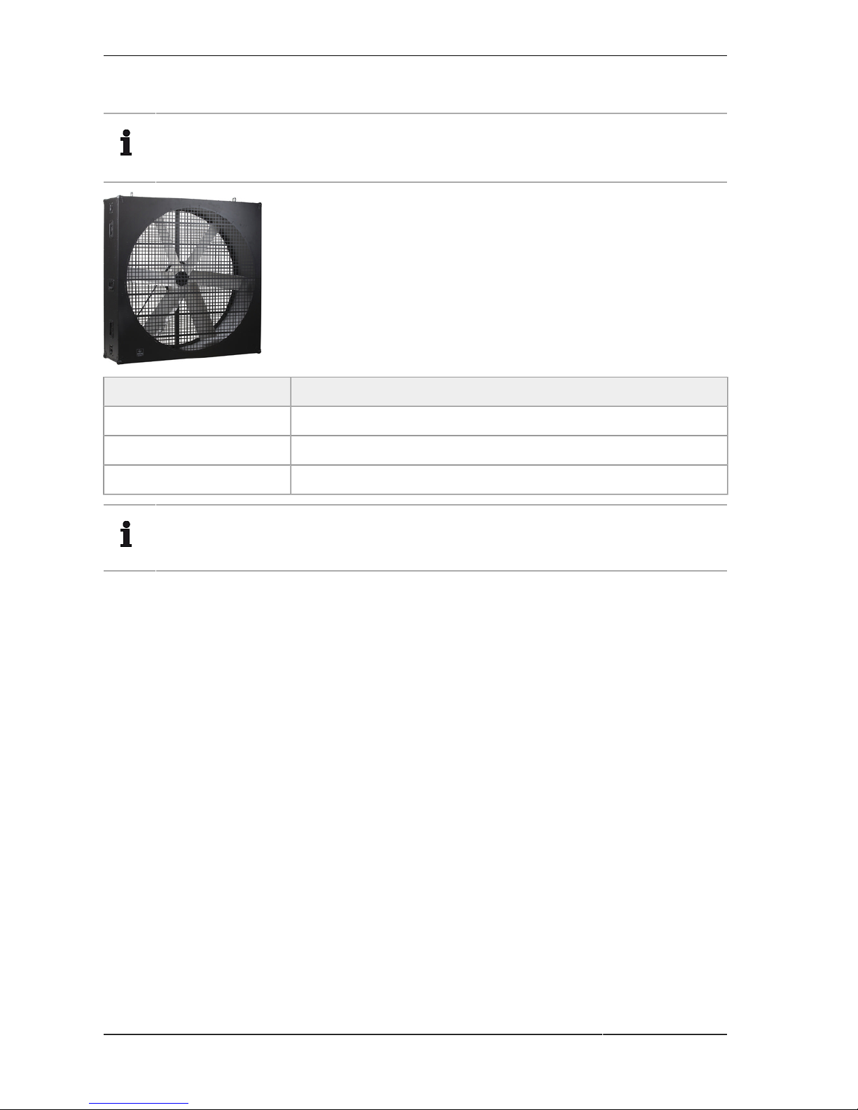
5 Description of devices
1
1
1
1
2
3
3
3
2
4
5
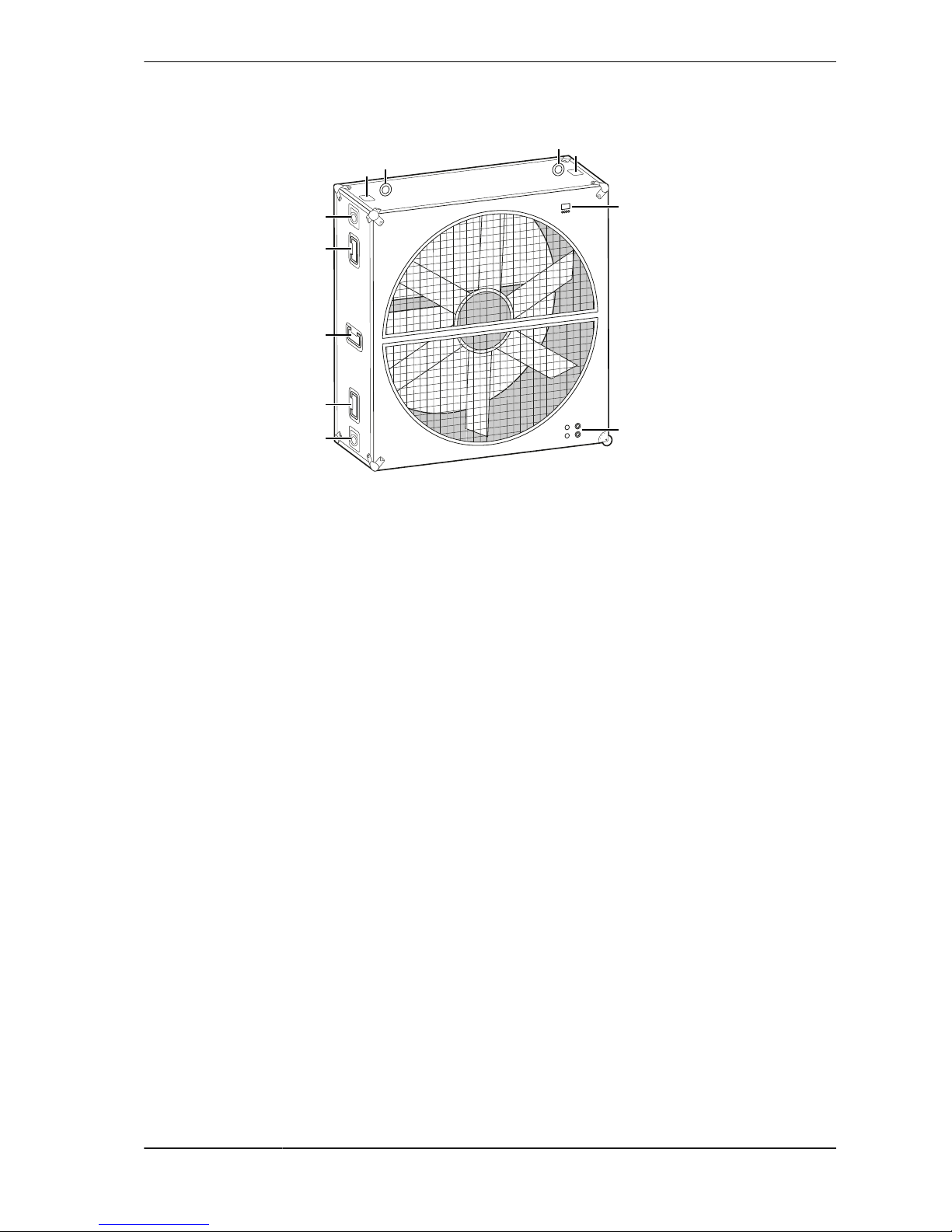
Image 1: Description - Force 120 (back)
1 Safety eyelets 4 Display with buttons
2 D-rings/suspensions (two-sided) 5 Connections
3 Carrying handles (two-sided)
Page 8
Assembly and connection
page 8/20 Operating Instructions Force 120 2018-03-02
6 Assembly and connection
6.1 Set up device
The device can be operated standing and hanging. With safety factor 12, a maximum of two devices can be
operated among each other.
Attention
High air flows. Objects in the area can be damaged or damage the Force 120.
■
Make sure that there are no light, unsecured objects up to 3 meters in front of and
behind the device.
Stationary
Condition(s)
■
The installation site has sufficient carrying capacity (at least 100 kg).
1. Place the device on the ground with the rubber feet.
2. Orient the device so that the front is clearly visible.
3. Secure the device with safety ropes.
✓
The device is set up and can be connected.
Hanging
1. Attach the brackets to the D-Rings.
2. Secure the device with safety ropes.
✓
The device is suspended and can be connected.
6.2 Connect the device
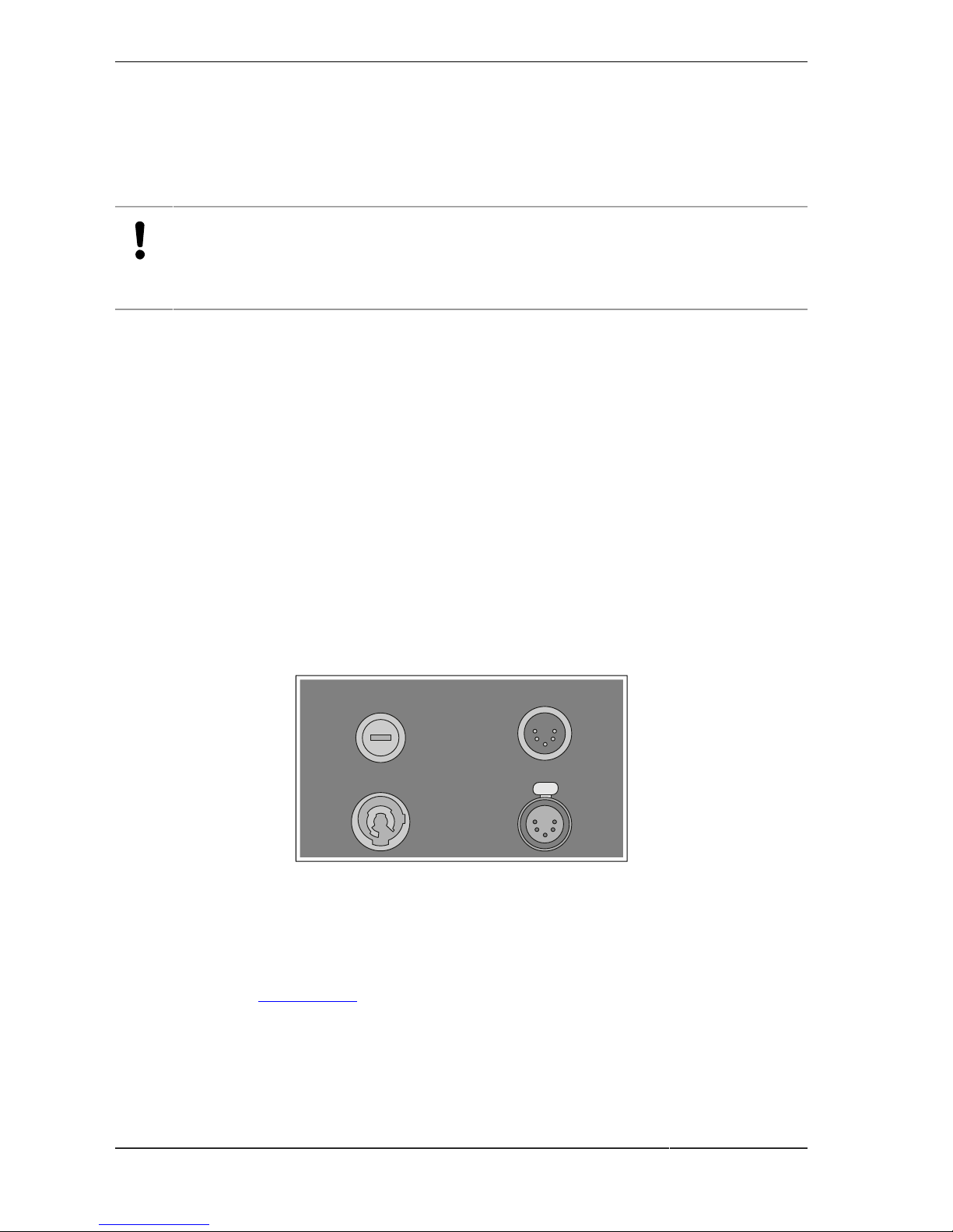
Connection panel
Fuse
T10A 220V
DMX In
Mains In
DMX Out
Image 2: Connection panel
Fuse: Fuse holder DMX in: DMX input (5-pin)
Mains in: Input PowerCON True1 DMX out: DMX output (5-pin)
Connect the device
Conditions
■
The device is set. (see chapter 6.1)
1. To establish the signal connection, connect the device and other devices or the controller with a DMX
cable. Therefore plug in the DMX cable DMX in and DMX out.
2. Plug in the PowerCON True1 cable into the PowerCON True1 input Mains in of the device.
3. Plug in the plug of the PowerCON True1 cable into a socket.
✓
The device is now connected and ready for use.
Page 9

Operation
2018-03-02 Operating Instructions Force 120 page 9/20
7 Operation
7.1 Control device
Control panel
1
2 3 4 5
Image 3: Control panel
1 Display 4 DOWN: Navigate up/increase value
2 MODE: Opens the main menu 5 UP: Navigate down/decrease value
3 ENTER: Open menu item or confirm setting
Use DMX control
Conditions
■
The device is connected with a DMX control.
■
The fan is not covered by other objects.
▶
Control the speed, acceleration and lighting with a DMX control.
✓
The device conducts the setup.
7.2 Menu structure
The menu structure consists of up to 5 menu levels.
7.2.1 DMX start address and setup
DMX start address
Level 2 Level 3 Level 4 Level 5 Value Description
1 - 505 DMX start address
Setup
Level 2 Level 3 Level 4 Level 5 Value Description
Normal
DMX mode
High
resolution
DMX input Wired DMX Use wired DMX as input
Page 10

Operation
page 10/20 Operating Instructions Force 120 2018-03-02
7.2.2 Settings
Level 2 Level 3 Level 4 Level 5 Value Description
Error
Blackout
ON / OFF
Light output is stopped
if an error occurs
Shutter
No DMX
Blackout
ON / OFF
Light output is stopped
if DMX fails for 3
seconds
Save
Save current positions
as initial positions after
reset without DMX
Init Positions
Reset
Reset initial positions
after reset without DMX
Linear
Set the desired
dimming curve
Soft
Dimming
Curve
Extra Soft
Hold
Last DMX values are
hold if DMX fails
Off
Fixture blacks out if
DMX fails
DMX hold
Fade out
Last DMX values are
hold if DMX fails
PWM
frequency
Set 582-618
Hz, 1200Hz,
2400Hz
Sets the LED PWM
frequency
Contrast 0 - 50 -100 % Contrast of the display
Brightness 0 - 100 %
Brightness of the
display (auto brightness
has to be disabled)
Blackout
time
1 - 10 -30 s
Time after which the
display blacks out after
last keystroke (auto
blackout has to be
enabled)
Normal Flip display up/down
Display
Display
orientation
Inverted
Page 11

Operation
2018-03-02 Operating Instructions Force 120 page 11/20
Level 2 Level 3 Level 4 Level 5 Value Description
Auto
Display is flipped
automatically by the
acceleration sensor if
fixture is hanging
No DMX
Flash
ON / OFF
Display flashes if DMX
fails
Reset factory
settings
Confirm
(yes/no)
Resets all values to
default (except for
serial number)
7.2.3 Information
Level 2 Level 3 Level 4 Level 5 Value Description
System
errors
List
Show all recent errors
(permanent)
System
versions
Main
(SW/HW)
Show all versions:
Software (main
application, boot
loader) & hardware
Total hours 0-99999 h
Time the fixture is
running in total
Fixture
hours
Resetable
hours
0-99999 h
(resettable)
Fixture
information
Boot count 0-99999
Count how often the
fixture was switched on
Fan 0 - 255 Show all DMX values
Speed/angle 0 - 255
Special/
control
0 - 255
Shutter 0 - 255
Dimmer 0 - 255
Red 0 - 255
Green 0 - 255
Blue 0 - 255
DMX input
monitor
Color 0 - 255
Page 12

Operation
page 12/20 Operating Instructions Force 120 2018-03-02
7.2.4 Manual control
Level 2 Level 3 Level 4 Level 5 Value Description
Reset
Full system
reset
Confirm
(yes/no)
Fan 0 - 255
Speed/angle 0 - 255
Special/
control
0 - 255
Shutter 0 - 255
Dimmer 0 - 255
Red 0 - 255
Green 0 - 255
Blue 0 - 255
Color 0 - 255
Manual DMX
Reset all
values
Confirm
(yes/no)
Set all manual DMX
values to 0
7.2.5 Test
Level 2 Level 3 Level 4 Level 5 Value Description
Pan ON / OFF
Color test ON / OFF
All test ON / OFF
7.2.6 Service
Level 2 Level 3 Level 4 Level 5 Value Description
Key code 0 - 255
Enter code first to get in
the service menu (reset
automatically after
fixture restart or after
10min with no display
input)
Serial 0 - 99999
Last 5 digits of the
serial number. Needed
for correct working
RDM
Red 0 - 128 - 255
Green 0 - 128 - 255
LED
calibration
LED1
Blue 0 - 128 - 255
Page 13

Operation
2018-03-02 Operating Instructions Force 120 page 13/20
7.3 Switch off device
▶
Disconnect the device from the power supply.
✓
The device is switched off.
Page 14

Cleaning and maintenance
page 14/20 Operating Instructions Force 120 2018-03-02
8 Cleaning and maintenance
Force 120 is a low-maintenance device. Depending on the operating environment, surfaces must cleaned
on a regular basis.
Warning
Danger of electrical shock. Electric cables can cause serious injury if they come into
contact with cleaning agents.
■
Disconnect the mains plug before cleaning.
■
Observe local health and safety regulations.
■
Wait until the device has cooled down after previous operation.
■
Do not repair the device yourself. Contact the customer service or retailer. (see
chapter 11)
1. Clean the surface with a dry, soft and clean cloth.
Attention
Do not use aggressive detergents, alcohol or other chemical agents.
2. Suck or sweep away dust from the openings.
✓
The cleaning is complete.
Page 15

Technical data
2018-03-02 Operating Instructions Force 120 page 15/20
9 Technical data
Version Force 120
Device dimensions 400 x 1,400 x 1,400 mm
15.75 x 55.12 x 55.12 inch
Weight (net) 94 kg
208 lbs
Supply voltage 100-240 VAC, 50-60Hz
Power (at 230 V) 1,000 W
DMX allocation 5 pin XLR: (+) = pin 3; (-) = pin 2; Ground = pin 1
Protection class IP20
Minimum / maximum
ambient temperature
-20 – 45 °C
-4 – 113 °F
Maximum fan speed 750 revolutions/min.
Minimum fan speed 30 revolutions/min.
Page 16

Recycling/disposal/environmental protection
page 16/20 Operating Instructions Force 120 2018-03-02
10 Recycling/disposal/environmental protection
Recycling
Dispose of packaging material in an environmentally friendly manner in accordance with local
waste disposal regulations.
Dispose of residues of operating materials in accordance with locally or operationally applicable
disposal regulations.
After decommissioning and disassembly of the system or individual components, these must be
disposed of in agreement with the manufacturer according to local regulations.
Do not dispose of batteries and rechargeable batteries in household waste. Dispose of batteries
and rechargeable batteries at designated collection points.
This device is marked in accordance with the European Directive 2012/19/EU on waste electrical
and electronic equipment.
Electrical and electronic devices must not be disposed of with household waste. Their components must be supplied separately for reuse and disposal.
At the end of its service life, return the device free-of-charge to the manufacturer, point of sale
or a public collection point set up for this purpose.
Page 17

Contact
2018-03-02 Operating Instructions Force 120 page 17/20
11 Contact
Manufacturer
GLP German Light Products, Inc.
1145 Arroyo Ave., Unit A
San Fernando, CA 91340
Support
Online www.germanlightproducts.com
To use the online support, it is required to go through a one-time registration
process. Then log into the online support using your registered user account.
E-mail support@germanlightproducts.com
Phone +1 818 767 8899
Page 18

Contact
page 18/20 Operating Instructions Force 120 2018-03-02
Page 19

Contact
2018-03-02 Operating Instructions Force 120 page 19/20
Page 20

GLP German Light Products, Inc.
1145 Arroyo Ave., Unit A
San Fernando, CA 91340
Phone: +1 818 767 8899
E-mail: Support@germanlightproducts.com
Website: www.germanlightproducts.com
 Loading...