

Page 1
Installation and Servicing
Flurocyl
Solar Hot Water Cylinder
14161
200 l
250 l
300 l
www.glow-worm.co.uk
1
Page 2

Guarantee Registration
Thank you for installing a new Glow-worm solar system.
Glow-worm products are manufactured to the very highest standard so we are pleased to offer our
customers a Comprehensive Guarantee.
This product is guaranteed for 24 months from the date of installation or 30 months from the date
of manufacture, whichever is the shorter, for parts and labour.
The second year of the guarantee, from the beginning of the 13th month onwards after installation
or manufacture, is conditional upon the product having been serviced by a competent person (i.e.
clear skies registered engineer),
in accordance with the manufacturer’s recommendations. We strongly recommend regular
servicing of your product, but where the condition is not met, any chargeable spare parts or
components issued within the applicable guarantee period still benet from a 12 month warranty
from the date of issue by the manufacturer.
The “Benchmark” Installation, Commissioning and Service Record must be completed on
installation and kept up to date.
We recommend you complete and return as soon as possible your guarantee registration card.
If your guarantee registration card is missing you can obtain a copy or record your registration by
telephoning the Glow-worm Customer Service number 01773 596510.
Customer Service:
01773 596510
Technical Helpline:
01773 828300
General and Sales enquiries:
Tel. 01773 824639
Fax: 01773 820569
To register your Glow-worm product call:
0800 0732142
2
Page 3

These instructions consist of, Installation, Servicing, Fault Finding and Replacement
of Parts. The instructions are an integral part of the product and must, be handed to
the user on completion of the installation.
CONTENTS DESCRIPTION SECTION PAGE
Warnings 4
Important Information 4
INTRODUCTION
Statutory Requirements 5
Safety Instructions 6
INSTALLATION
MAINTENANCE
Product Specications 1 6
Installation 2 11
Commissioning 3 18
Inspection and Maintenance 4 19
Fault Finding 5 20
3
Page 4

WARNINGS
SAFETY
The urocyl must be installed by a competent person, who is responsible for adhering to
the existing standards and regulations.
ALTERATIONS
Under no circumstances should you ever attempt to make alterations to these
components or any other part of the system
SEALED COMPONENTS
Under no circumstances must the user interfere with or adjust sealed parts.
Important Information
Installation and Use Regulations
In your own interests and that of safety, it is the LAW that this
product is installed by a competent person in accordance
with the current issue of these regulations.
Control of Substances Hazardous to Health
Under Section 6 of The Health and Safety at Work Act
1974, we are required to provide information on substances
hazardous to health.
The adhesives and sealants used in this product are cured
and give no known hazard in this state.
Manual Handling
With regards to the “Manual Handling Operations, 1992
Regulations”, the appliance exceeds the recommended
weight for a one man lift.
Electrical Supply
The product MUST be earthed.
All system components shall be of an approved type and all
wiring to current I.E.E. wiring regulations.
External wiring must be correctly earthed, polarised and in
accordance with the relevant standards.
In GB, this is BS 7671.
In IE, this is the current edition of ETCI rules.
The product MUST be connected to a permanent 230V ac,
50Hz supply.
Connection of the whole electrical system of the product,
including any heating controls, to the electrical supply MUST
be through one common isolator and must be fused 3 Amp
maximum.
Isolation should be by a double pole switched fused spur box,
with a minimum gap of 3mm for both poles. The fused spur
box should be readily accessible and preferably adjacent to
the product. It should be identied as to its use.
Alternatively connection can be made through an unswitched
shuttered socket and 3A fused 3-pin plug both to the current
issue of BS 1363, provided they are not used in a room
containing a bath or shower.
Wiring to the product must be PVC 85°C insulated cable, not
less than 0.75mm2 (24/0.20mm).
Testing and Certification
This product is tested and certicated for safety and
performance. It is, therefore, important that no alteration is
made to the product, without permission, in writing, by Glowworm.
Any alteration not approved by Glow-worm, could invalidate
the certication, warranty and may also infringe the current
issue of the statutory requirements.
CE Mark
The CE mark on the Fluropro solar control indicates that
it complies with the basic requirements of the applicable
directives as stated on the data badge.
“Benchmark scheme”
Glow-worm support the Benchmark initiative. It is very
important that the service record is completed by the
installation engineer and handed over to the user.
4
Page 5

Statutory Requirements
IMPORTANT:
Where no British Standards exists, materials and equipment
should be t for their purpose and of suitable quality and
workmanship.
The installation of this product must be carried out by a
competent person in accordance the rules in force in the
countries of destination.
Manufacturer’s instructions must not be taken as overriding
statutory requirements.
Statutory Requirements
In GB, the installation of the product must be carried out by a
competent person as described in the following regulations:
The manufacturer’s instructions supplied.
The Gas Safety (Installation and Use) Regulations.
The appropriate Buildings Regulations either The Building
Regulations, The Building Regulations (Scotland),The
Building Regulations (Northern Ireland).
The Water Fittings Regulations or Water byelaws in Scotland.
The Health and Safety at Work Act, Control of Substances
Hazardous to Health (COSHH).
The Current I.E.E. Wiring Regulations.
Where no specic instructions are given, reference should be
made to the relevant British Standard Code of Practice.
In IE, the installation must be carried out by a competent
person and installed in accordance with the current edition
of I.S.813 “Domestic Gas Installations”, the current Building
Regulations and reference should be made to the current
ETCI rules for Electrical Installation.
GB: the following Codes of Practice apply:
BS4814, BS6798, BS5440 Part 1 and 2, BS5546 Part 1,
BS5449, BS6891, BS6700, BS7074 Part 1 and 2, BS7593,
BS7671.
IE: I.S.813, BS5546, BS 5449, BS 7074, BS 7593.
NOTE: For further information, see the current issue of the
Building Regulations, approved document L1 ( in the UK) and
the following current issues of:
1) Central heating system specication (CheSS)
and
2) Controls for domestic central heating system and hot water.
BRECSU.
Domestic Hot Water
All domestic hot water circuits, connections, ttings must be
in accordance with the relevant standards and water supply
regulations.
GB: Guidance G17 to G24 and recommendation R17 to R24
of the Water Regulations Guide.
IE: The current edition of I.S.813 “Domestic Gas Installations”.
Heating System
In GB, it is necessary to comply with the Water Supply (Water
Fittings) Regulations 1999 (for Scotland, the Water Byelaws
2000, Scotland).
To comply with the Water regulations your attention is drawn
to: The Water Regulations guide published by the Water
Regulations Advisory Service (WRAS) gives full details of the
requirements.
In IE, the requirements given in the current edition of I.S.813
“Domestic Gas Installations” and the current Building
Regulations must be followed.
Solar cylinder and cylinder installation
Pressure equipment directive 97/23/EC Directive of the
European Parliament and Council from 29th May, 1997 for
the approximation of the laws on pressure equipment of the
Member States
EN 12977-3 Thermal solar systems and components; Custom
built systems, Part 3: Performance characterisation of stores
for solar heating systems
EN 12897 Water supply - specication for indirectly heated
unvented (closed) storage water heaters
EN 806-1 Specications for installations inside buildings
conveying water for human consumption - Part 1: General
EN 1717 Protection against pollution of potable water
installations and general requirements of devices to prevent
pollution by backow
EN 60335-2-21 Safety of household and similar electrical
appliances; Part 2: Particular requirements for storage water
heaters (hot water cylinders and hot water boilers) (IEC 335-
2-21: 1989 and supplements 1; 1990 and 2; 1990, modied)
Regulations in Great Britain
Building Regulation, dating from 1991 (England and Wales)
Requirement G3, L1 and Regulation 7
BS 7671 Requirements for electrical installations (IEE Wiring
Regulations, 16th edition)
BS 6759-1 Directive for the usage of the safety assembly for
hot water cylinders
5
Page 6

Safety Instructions
Safety instructions
NOTE: In the event of leaks in the water pipework close the
main cold water stop valve. This is often located under a
kitchen sink.
IMPORTANT: A thermostatic mixing valve must be tted to
the outlet of the cylinder and can be adjusted to the desired
domestic hot water temperature by an installation or service
engineer. Otherwise there is a risk of scalding as the cylinder
outlet temperature at the taps could be up to 85°C.
IMPORTANT: Risk of damage! Do not remove or modify any
components of the solar cylinder.
In the unlikely event of a malfunction occurring of the Flurocyl,
such as hot water owing out of the temperature and pressure
relief valve, switch off the boiler and the immersion heater and
contact Glow-worm or your installer.
Frost protection of the twin coil solar cylinder
You must drain the solar cylinder completely if it is to be shut
down in a room prone to frost. It is drained at the cold water
inlet with a T-piece with tap to be provided by the installer.
Also drain all heat exchangers which are not lled with solar
uid.
1 Product Specications
Unit Flurocyl 200 l Flurocyl 250 l Flurocyl 300 l
Cylinder:
Size l 200 250 300
Maximum water supply pressure bar 10
Operating pressure bar 3.5
Pressure limiting valve bar 3.5
Expansion relief valve bar 6.0
Hot water expansion vessel admission pressure bar 4.0
Temperature and pressure relief valve °C/bar 95 / 7.0
Net weight kg 39 44 49
Weight (full) kg 245 310 340
Height mm 1499 1789 2109
Cylinder connections:
Cold water supply 22 mm pressure pipe
Hot water connection 22 mm pressure pipe
Pressure-controlled cold water outlet 22 mm pressure pipe
Secondary return Inches G 3/4
Flow (boiler/solar circuit) 22 mm pressure pipe
Return (boiler/solar circuit) 22 mm pressure pipe
Electrical connections:
3 kW immersion heater (according to ENBS 60335) 230/240 V, 50 Hz
Length of the immersion heater mm 430
Motorised 2 port valve 230/240 V, 50 Hz
Cylinder thermostat 230/240 V, 50 Hz
Thermal cut out for solar pump 230/240 V, 50 Hz
Heating coil:
Heat loss kW/24 h 1.9 2.1 2.4
Heat up time (boiler part) mins 21 26 30
Recovery (boiler part) mins 13 16 21
Table 1.1 Technical data
6
Page 7
1 Product Specications
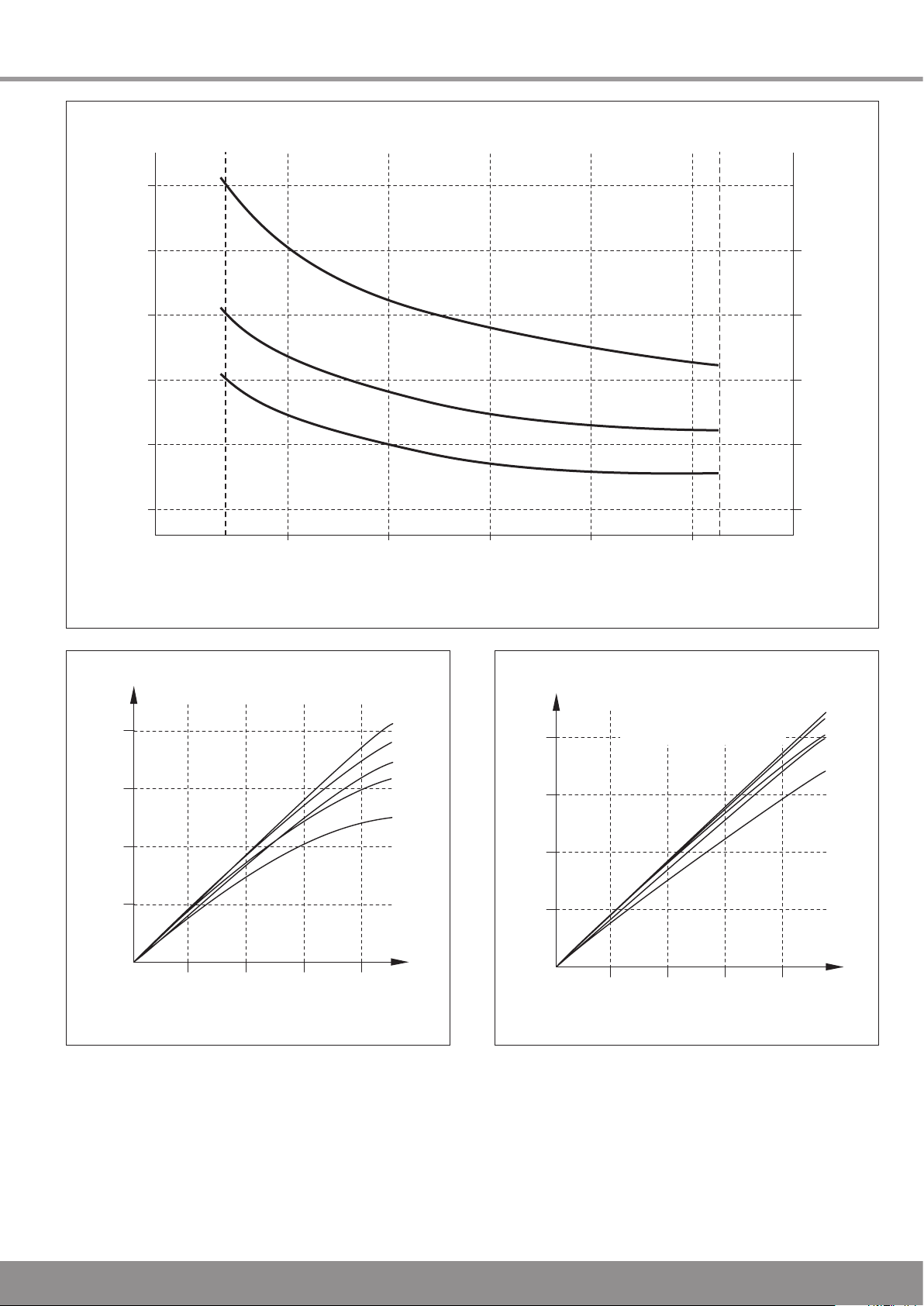
Approximate cylinder heat up time 15 C to 45 C (minutes)
Reheat time for 70 % of cylinder contents (minutes)
10
15
20
25
30
20
25
30
35
40
45
12
Heat input to cylinder (kW)
15 20 25 30 3835
200 l
250 l
300 l
40
40
8 bar
4 bar
3 bar
2 bar
1 bar
30
30
20
20
Flow available (litres/min) at entry to system
Flow out (litres/min) of the system
10
10
0
8 bar
4 bar
3 bar
2 bar
1 bar
Flow available (litres/min) at entry to system
Flow out (litres/min) of the system
40
40
30
30
20
20
10
10
0
Mixed water of 40 °C, mixed from
60 % hot water of 60 °C and
40 % cold water of 10 °C
14177
Flurocyl cylinder heat-up times (boiler part)
14178
Flurocyl DHW flow rates at 60°C Flurocyl mixed water flow rates
NOTE: The heat-up time is based on a primary ow rate of 9
l/min at 80 °C. Temperature rise from 15 °C to 65 °C
Static operating pressure of the cold water supply
The displayed ow rates apply to installations in which the
cold water supply is of appropriate dynamic pressure.
Please contact Glow-worm if the static water pressure is
below 1 bar.
Diagram 1.2
7
Diagram 1.1
14179
Diagram 1.3
Page 8
1 Product Specications
CARRYING
HANDLE
1.1 Intended use
The Glow-worm Flurocyl 200 l, Flurocyl 250 l and Flurocyl 300
l are unvented, indirectly heated hot water cylinders for use
with solar systems and boilers for the provision of domestic
hot water.
IMPORTANT: Risk of damage! The appliances may only
be used to heat up potable water. Damage to the appliance
due to corrosion cannot be excluded if the water does not
correspond to the specications of the water ordinance.
Any other use or extended use is considered to be improper.
The manufacturer/supplier is not liable for any resulting
damage.
Intended use includes the observance of the instructions and
the adherence to the servicing requirements.
1.2 Data badge
The data badge has been applied to the top of the solar
cylinder by the manufacturer.
1.3 Safety devices
The Flurocyl solar cylinder has been provided with all safety
and control devices suitable for operation as part of an
unvented domestic hot water supply system.
Temperature and pressure relief valve (95°C, 7 bar)
Pressure limiting valve (3.5 bar) with line strainer
Expansion relief valve (one port valve, 6.0 bar)
Thermal cut out set to 90°C, connected to the solar pump in
order to isolate this heat source in the event of failure of the
solar control.
Thermal cut out of the immersion heater
Thermal cut out set to 90°C, connected to the motorised 2
port valve, in order to isolate the primary heat source in the
event of failure of the domestic water thermostat.
1.4 Safety regulations
This product has been checked for adherence to the building
regulations for unvented hot water cylinder systems. It may
not be changed or modied in any way whatsoever.
It should be installed by a qualied specialist, who should
observe the applicable regulations of the local authorities, the
building regulations, the building regulations for Scotland, the
building regulations for Northern Ireland and the directives of
the local water supply companies. Only original spare parts
may be used for the replacement of parts.
1.7 Solar Cylinder Charicteristics
Flurocyl solar cylinders are available in three sizes: 200, 250
and 300 litres. The containers are made of stainless steel
and insulated with EPS.The cylinders are equipped with all
necessary cold and hot water control devices and a motorised
2 port valve.
The Flurocyl cylinders are operated at the pressure of the
water supply pipe and do not need a cold water tank for their
supply. They have hot and cold water connections of 22 mm
diameter. A cold water supply of appropriate pressure and
ow rate is required to operate the solar cylinder ideally, refer
to section 2.6.
Temperature control
The solar water heating control thermostat is part of the solar
control with sensor attached to the Flurocyl solar cylinder.
The cylinder includes the boiler and imersion heater control
thermostats that are factory tted and set.
A themostatic mixing valve must be tted to the outlet of the
cylinder and must be adjusted to the desired domestic hot
water temperature.
The cylinder also includes the solar, boiler and immersion
heater thermal cut outs that are factory tted and set.
The solar pump must be connected to the solar control via
the solar thermal cut out (TCO), It ensures the solar pump is
switched off if the hot water temperature in the cylinder rises
above 90°C.
Immersion heater
The Flurocyl solar cylinders are equipped with an additional
immersion heater of 3 kW, including the control thermostat
and thermal cut out. The immersion heater is situated behind
the front plate.
NOTE: In the event of a replacement, only the right immersion
heater equipped with a thermal cut out fur overheating
protection may be used.
1.5 Contents
Check the contents of the pack, see diagram 2.1.
Make sure the cylinder is stored in an upright position in a dry
environment prior to its installation.
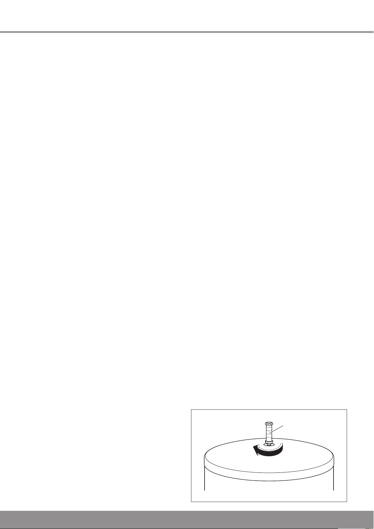
1.6 Transport
A cylinder carrying handle is supplied to make the transport to
the installation site easier.
Fasten the carrying handle to the hot water outlet connection
of the solar cylinder.
Carrier handle
8
14180
Diagram 1.4
Page 9
F
D
E
G
C
A
B
554
598
45°
H
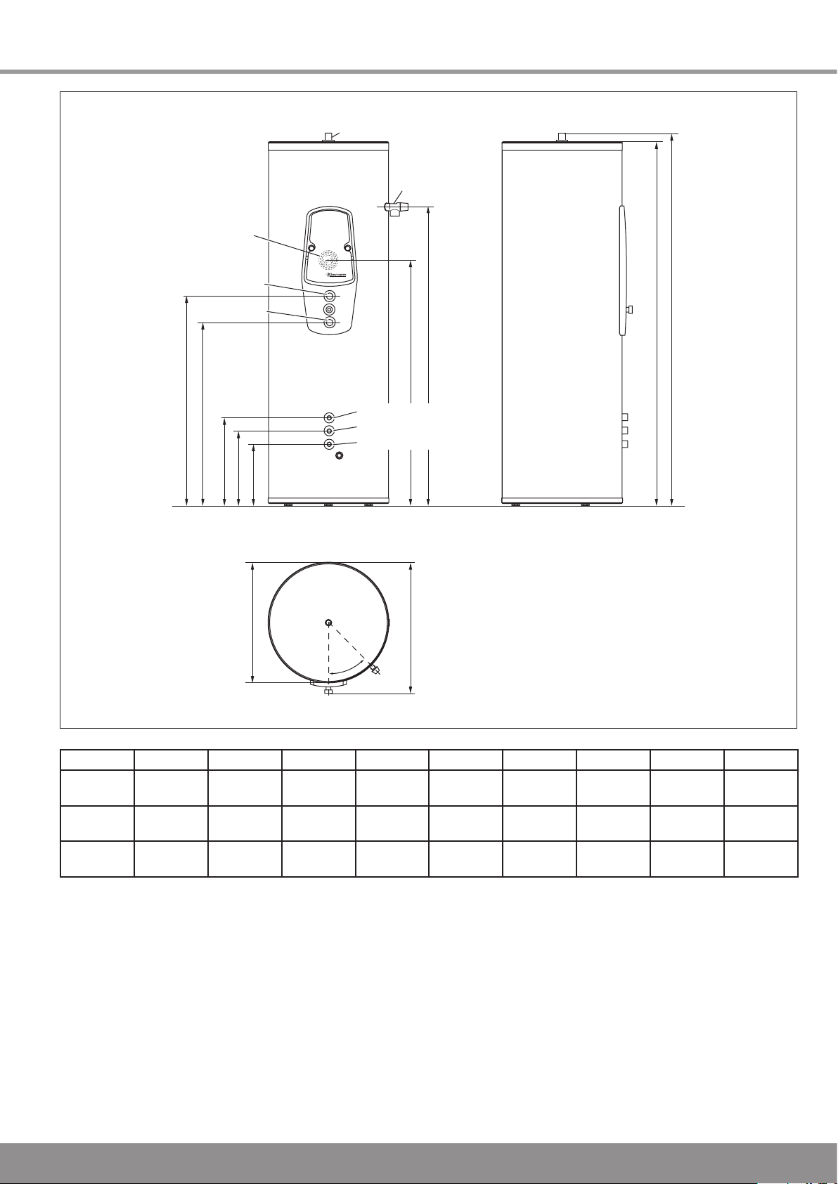
ot water connection
Temperature
and pressure
relief valve
Solar circuit Flow
Cold water supply
Solar circuit Return
H
I
Immersion
heater
Boiler Flow
Boiler Return
1 Product Specications
14181
Dimensions
Flurocyl
200 l
Flurocyl
250 l
Flurocyl
300 l
Diagram 1.5
A B C D E F G H I
1468 1499 454 384 314 589 1118 813 953
1758 1789 454 384 314 589 1408 924 1064
2078 2109 454 384 314 589 1648 1101 1241
Table 1.2 Dimensions
9
Page 10

Boiler
Flow Return
Flurocyl
Flurosorb
Solar Pump Unit
Flow
Return
Immersion
Heater
Drinking Water
Expansion Vessel
2 Port Valve
2 Port Valve
Automatic Air
Separator System
M
DHW
M
Protection
Vessel (optional)
Solar Expansion Vessel
1 Product Specications
14162
Diagram 1.6
10
Page 11
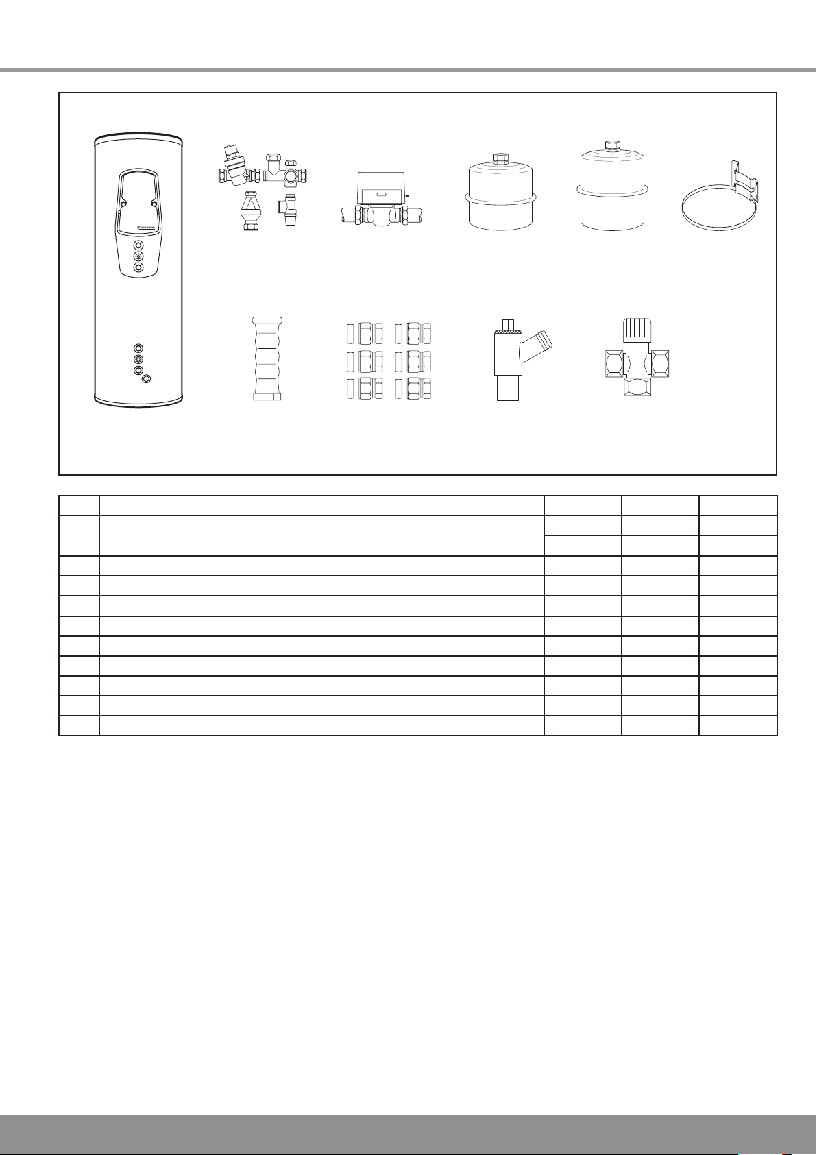
2 Installation
A B
7 8 9 10
2 3 4 5 6
1
14173
Flurocyl pack contents
Item Description Qty. Qty. Qty.
1 Flurocyl solar cylinder
Part no.
2 Cold water control pack with tundish 1 1 1
3 Motorised 2 port valve 1 1 1
4 DHW expansion vessel 18 l 1
5 DHW expansion vessel 25 l 1 1
6 DHW Expansion vessel mounting bracket 1 1 1
7 Carrying handle 1 1 1
8 Compression Fittings 1 1 1
9 Drain valve 1 1 1
Thermostatic Mixing Valve 1 1 1
10
200 l 250 l
307 206 307 207 307 208
Table 2.1 Flurocyl pack contents
Diagram 2.1
300 l
11
Page 12

2 Installation
Legionella loop
return connection
Cylinder
thermostat
Cylinder thermostat
thermal cut out
Immersion heater
thermostat
Immersion heater
thermal cut out
Immersion
heater
Domestic hot water
outlet connection
Temperature and
Pressure relief valve
Expansion vessel
connection
Pressure controlled
cold water outlet
Cold water
supply
Return
(solar circuit)
Adjustable feet
Flow (solar circuit)
Return
(boiler)
Flow (boiler)
Solar pump thermal
cut out
Immersion
heater
switch
Pressure
limiting
valve
Expansion
relief
valve
Tundish
Cylinder drain valve
Temperature sensor immersion sleeve
Expansion
vessel
REAR VIEW
30°
4
0
°
5
0
°
65°
30°
4
0
°
5
0
°
65°
LN
1 2 3
14174
2.1 Locating the cylinder
Locate the solar cylinder at an appropriate place in the
building, while observing the following:
The discharge pipe from the tundish must be installed at a
minimum slope of 1:200 and end at a safe and visible point,
refer to section 2.9.
The installation surface must be level and able to bear the
weight of the full cylinder, refer to table 1.1.
The installation site may not be prone to frost. A frost
protection thermostat must be installed if necessary.
There must be sufcient space to install, check and
repressurise the expansion vessel.
Floor unevenness should not be greater than the
compensation offered by the adjustable feet of the solar
cylinder.
2.2 Boiler heating circuit piping
Copper pipes with a minimum diameter of 22mm should be
used for the pipes in the reheating circuit between the boiler
and the solar cylinder.
Larger pipe diameters may be necessary for relatively large
distances between the boiler and the cylinder.
2.3 Motorised 2 port valve
To prevent the Flurocyl cylinder from overheating the 2 port
motorised valve supplied must be tted to the primary ow to
the indirect coil.
2.4 Domestic hot water pipework
Connect the hot water outlet to the 22mm hot water
connection of the solar cylinder.
Lay a further 22mm pipe to the rst T-piece.
A pipe of 15mm diameter should then be sufcient.
If the pipe is very long or several outlets are supplied,
continue with another 22mm pipe.
2.5 Thermostatic mixing valve
A hot water thermostatic mixing valve ensures the hot water
from the cylinder is mixed with cold water to a desired
maximum temperature between 30°C and 60°C.
Set the thermostatic mixing valve to the desired maximum
temperature during the solar system commissioning.
IMPORTANT: Risk of scalding, Set the thermostat mixer to
60°C or below and check the temperature at a hot water tap
to ensure effective protection against scalding.
Diagram 2.2
12
Page 13

2 Installation
TUNDISH
THERMOSTAT
MIXER
EXPANSION
VESSEL
HOT
WATER
CONNECTION
TEMPERATURE
AND PRESSURE
RELIEF VALVE
(95 °C, 7 BAR)
LEGIONNELLA
LOOP (optional)
FLOW
PUMP
BOILER
PRESSURE
LIMITING VALVE
(3.5 BAR)
WITH LINE
STRAINER
EXPANSION
RELIEF
VALVE
(6.0 BAR)
COLD
WATER
SUPPLY
FLUROCYL
DRAIN VALVE
MOTORISED
2 PORT VAVE
MOTORISED
2 PORT VAVE
RETURN
14244
2.6 Mains water supply
The performance of unvented cylinders depends on the
available mains water pressure and the pipe size.
In order for the performance of the Flurocyl solar cylinder to
be ideal, an appropriate cold water supply must be available.
The measured static pressure must be at least 2.0 bar. A
corresponding ow rate of at least 20 - 25 l/min should be
available.
NOTE: The mains water pressure is reduced during periods of
high water consumption.Make sure you take measurements
during these periods.
Diagram 2.3
Example: The available ow rate of mixed water at 40°C is 25
l/min (15 l/min hot water of 60°C from the solar cylinder mixed
with 10 l/min cold water of 10°C) if the measured static cold
mains water pressure is 2 bar.
The solar cylinder operates satisfactorily at a mains water
pressure of below 2 bar, but at a reduced ow rate.The
unvented solar cylinder should not be installed if the mains
water pressure is below 1 bar.You can obtain information on
alternative hot water supply systems from Glow-worm.
To keep the friction losses at a minimum, a minimum diameter
of 22mm is recommended for the cold water supply in the
building, satisfactory performances can also be achieved with
15mm pipes however.
13
Page 14

2.7 Cold water inlet controls and pipework
COLD
WATER
SUPPLY
PRESSURE LIMITING
VALVE WITH LINER
STRAINER
BALANCED
PRESSURE
COLD WATER
CONNECTION
HOT WATER
EXPANSION
VESSEL
CONNECTION
EXPANSION
RELIEF VALVE
FLUROCYL
CONNECTION
LEGIONELLA
LOOP
CONNECTION
Connect both parts of the water control pack.
When installing the valves, make sure they are aligned in
such a way that the 15mm connection of the expansion relief
valve can be connected to the tundish.
Install the assembled water control pack in the cold water
supply at an appropriate place next to the solar cylinder.
Make sure there is sufcient space for maintenance and the
connection of the discharge pipe from the expansion relief
valve.
Install the drain valve in the cold water supply at the lowest
point between the solar cylinder and the water control pack.
We recommend applying a hose, which reaches about 1m
under the base of the cylinder, to the outlet of the drain valve.
IMPORTANT: Risk of bursts for the solar cylinder! No stop
valve may be installed between the cold water control pack
and the cylinder.
Install the water pack so that a discharge pipe of the
expansion relief valve can be tted with constant outward
slope which can end at a safe, visible point where there is no
risk of freezing.
IMPORTANT: Risk of the solar cylinder bursting due to
overpressure! The outlet of the expansion relief valve must
not be covered or closed.
Test the expansion relief valve regularly to avoid calcication.
To ensure an optimum performance of the solar cylinder, in
particularly buildings in which a pressure controlled cold water
is used, copper pipes with a diameter of at least 22mm should
be used for the pipe from the main stop valve of the building
to the solar cylinder.
If the discharge pipes are all together, the expansion relief
valve may not be installed more than 500 mm away from the
temperature and pressure relief valve.
The Flurocyl solar cylinder is supplied with an external hot
water expansion vessel (DW EV).
Connect this expansion vessel to the installed water control
pack as follows:
Screw the expansion vessel directly onto the water control
pack, via the connection intended for this purpose or
Connect the expansion vessel to the water control pack with a
copper pipe or an appropriate hose. Make sure the expansion
vessel is supported sufciently.
Use the supplied mounting bracket if the expansion vessel is
to be mounted on the wall.
Connect thermostatic mixing valve cold supply to the pressure
controlled cold water connection of the water control pack (if
convenient).
NOTE: In areas with high water pressure (4 bar or more), a
bath or shower mixer valve could also be connected to the
pressure-controlled cold water connection of the water control
pack. This is to ensure the pressure of the hot and cold water
supply to the mixer valve is about the same. Any second
cold water supply connection should be installed between
the water control pack and the solar cylinder by means of a
T-piece.
2 Installation
14187
Diagram 2.4
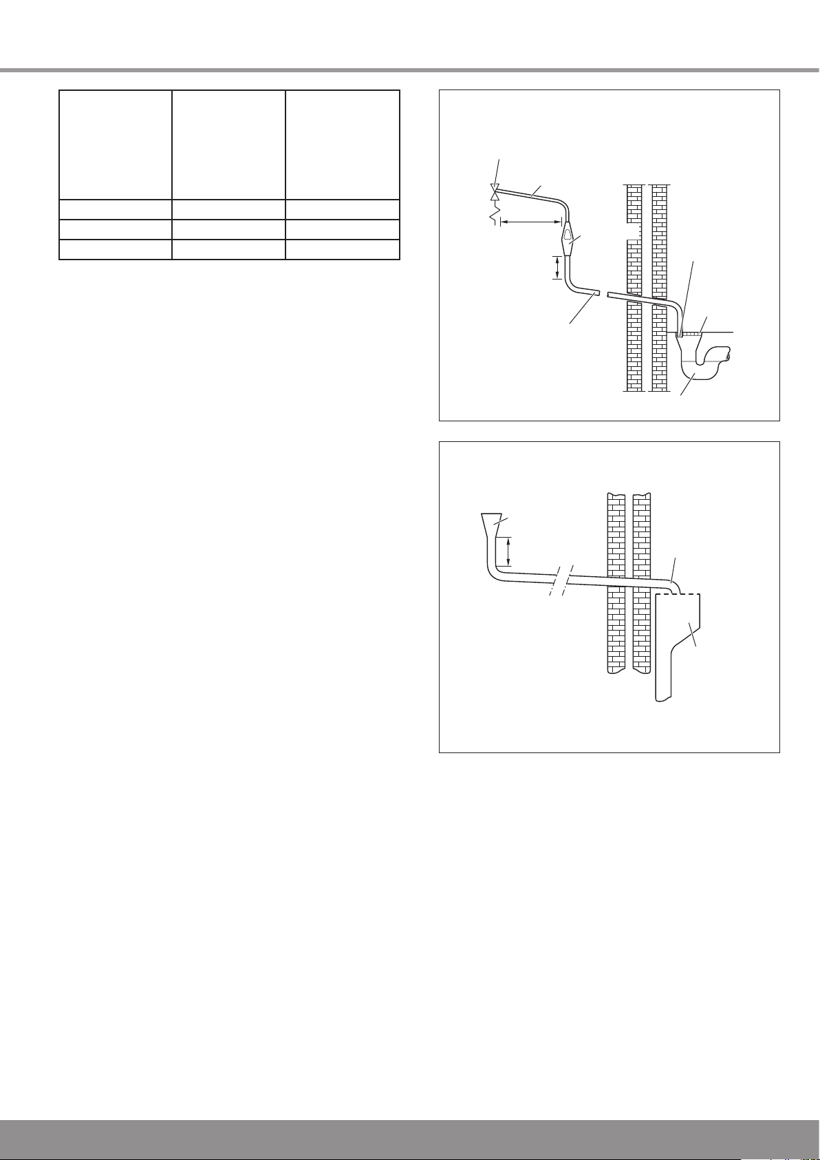
2.8 Discharge pipework
The outlet connections of both the temperature / pressure
relief valve and expansion relief valve should be connected in
15mm copper pipe to the tundish supplied. The tundish should
be installed vertically, as close to the Flurocyl as possible and
within 500mm of the temperature and pressure relief outlet. It
must be positioned away from any electrical components and
installed in the same space as the Flurocyl cylinder, so that
it is visible to the user. The D1 discharge pipe from the T&P
Valve/Expansion valve can be teed together upstream of the
tundish.
The discharge pipework must be installed using minimum
22mm copper pipework from the 22mm connection on the
tundish to a safe and visible discharge point.
There must be a vertical section of pipe at least 300mm
long, below the tundish before any bends or elbows in
the pipework. Increase the diameter of the pipework if the
total resistance of the discharge pipework exceeds the
gures shown in table 2.2. The installation of the discharge
pipework must be in accordance with G3 refer to Statutory
Requirements.
14
Page 15
METAL DISCHARGE PIPE FROM
TEMPERATURE RELIEF VALVE
TO TUNDISH
METAL DISCHARGE PIPE
FROM TUNDISH WITH
CONTINUOUS FALL
TUNDISH
DISCHARGE
BELOW
FIXED
GRATING
FIXED
GRATING
TRAPPED GULLY
SAFETY DEVICE
(E.G. TEMPERATURE
RELIEF VALVE
VENTIL)
500 MM
MINIMUM
300 MM
MINIMUM
TUNDISH
300 MM
MINIMUM
DISCHARGE
PIPE
METAL
HOPPER
HEAD
2 Installation
Minimum diameter
of the discharge
pipe from the
tundish
22mm
28mm Up to 18m 1.0m
35mm Up to 27m 1.4m
Examples:
22mm discharge pipe with 4 elbows and of 7m length from the
tundish to the discharge point:
Resistance for 4 elbows per 0.8m = 3.2m
Resistance for discharge pipe = 7.0m
Total resistance = 10.2m
The total resistance of the discharge pipe is higher than the
maximum permissible value for 22mm pipes (9m). Base your
calculations therefore on the next largest pipe diameter.
28mm discharge pipe with 4 elbows and of 7m length from the
tundish to the discharge point:
Resistance for 4 elbows per 1.0m = 4.0m
Resistance for discharge pipe = 7.0m
Total resistance = 11.0m
The total resistance of the discharge pipe is lower than the
maximum permissible value for 28mm pipes (18m),which
means this pipe diameter can be used.
Water which is almost boiling may escape from the discharge
pipe in the event of an error.
IMPORTANT: Risk of being scalded by escaping hot water!
Make sure the discharge pipe ends at a safe point inside or
outside the building (safe and visible), where there is no risk
of anyone coming in contact with hot water.
A suitable point is, for example, under a xed grating above
the trap of a trapped gully. Low discharge pipes, for example
up to 100mm above external surfaces, such as parking
spaces, grasslands etc., can be used, provided they are
secured by a wire fence or something similar to prevent
children from coming in contact with the waste water, and the
system is visible. No valves or taps may be installed in the
discharge pipe.
Make sure the discharge pipe is at a constant slope of at least
1:200 from the tundish to the discharge point.
The discharge pipe from the pressure relief valve of the boiler
(if applicable) can be connected to the horizontal discharge
pipe of the solar cylinder behind the tundish with a T-piece.
2.9 High level discharge termination
Providing that the point of termination is such that persons
in or around the building will not be endangered should
discharge take place, this method of termination is
satisfactory. Points to consider when deciding whether a
location for the high level of discharge is suitable are:
Maximum
permissible
total resistance,
expressed as
straight pipe
length (without
elbows or bends)
Up to 9m 0.8m
Resistance due
to each elbow
or bend (straight
length equivalent)
Table 2.2 Resistance
14188
Diagram 2.5
14189
Diagram 2.6
The possibility, taking into account wind effect, that someone
may be in the path of the water being discharged and if so,
whether the temperature of the discharge water will have
been sufciently reduced to not be dangerous. Thermal
conductivity of the structure's surface, climatic conditions and
location and orientation of the discharge pipe may or may not
have an effect on reducing the temperature of the discharge
water.
The location of windows and similar openings.
The likelihood of a pram being left beneath the point of
discharge.
The ability of structures surface to withstand near boiling
water.
The possibility of ice formation if water is discharged onto
pedestrian walkways.
15
Page 16
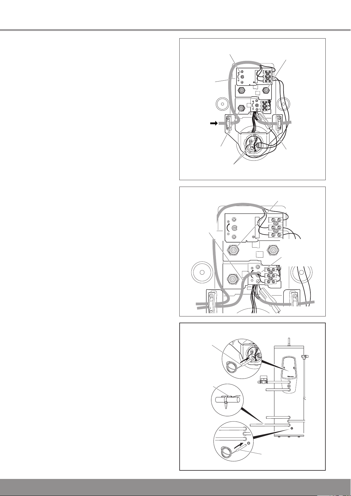
2 Installation
IMMERSION HEATER
THERMAL CUT OUT
WITH RESET BUTTON
REHEAT
THERMAL
CUT OUT WITH
RESET BUTTON
REHEAT
THERMOSTAT
(FACTORY SET)
IMMERSION HEATER
THERMOSTAT
(FACTORY SET)
IMMERSION
HEATER
CONNECTION
230V AC 3 kW
TEMPERATURE SENSORS
IN IMMERSION SLEEVES
230V
AC
3 kW
30°
4
0
°
5
0
°
65°
30°
4
0
°
5
0
°
65°
LN
1 2 3
UPPER
TEMPERATURE
SENSOR
LOWER
TEMPERATURE
SENSOR
TEMPERATURE
SENSOR
GAIN
3
0
°
40
°
50°
65°
3
0
°
40°
50°
65°
LN
1 2
3
DOMESTIC
HOT WATER
DEMAND
WIRING
REHEAT
CONTROL
THERMOSTAT
(FACTORY SET)
SOLAR THERMA
L
CUT-OUT WITH
RESET BUTTON
2.10 Electrical installation
Remove the front fascia panel.
Wiring should be performed by a competent person in
accordance with the building regulations, Part P of the
current IEE regulations and further applicable regulations and
directives.
The discharge pipes of the tundish, drain valves, motorised
valves etc. should be laid at a safe distance to electrical
components.
IMPORTANT: Danger of death from electric shock! You must
earth the solar cylinder for potential equalisation.
2.11 Immersion heater
The Flurocyl solar cylinders incorporate an immersion heater.
IMPORTANT: Danger of death from electric shock! You must
earth the immersion heater for potential equalisation.
Install a separate electrical power supply line for the
immersion heater in accordance with current IEE regulations
(BS 7671).
You must lay a heat-resistant line (3 x 2.5 mm
pole isolating switch for the immersion heater. The circuit must
be protected by a 13 A fuse.
The connection of the immersion heater is illustrated in detail
in diagram 2.7.
IMPORTANT: Risk of damage! The immersion heater
is equipped with a thermal cut out and may under no
circumstance be replaced by a standard immersion heater.
Only correct original Glow-worm spare parts are permitted.
2
) from a double
14190
Diagram 2.7
14192
2.12 Thermostat setting
The entire inner wiring has been pre-assembled at the factory.
IMPORTANT: Risk of damage! Switch off the power supply
before resetting the thermal cut out or making any other
changes to the temperature setting of the cylinder thermostat.
The cylinder thermostats for the regulation of the hot water
temperature are factory set at 65°C as the Domestic Hot
Water temperature is controlled by the adjustable thermostatic
mixing valve.Ensure both control thermostats are adjusted
fully clockwise.
Actuate the reset buttons, to reset the thermal cut outs if
necessary, see diagram 2.7.
IMPORTANT: Risk of damage! If the immersion heater is not
connected, you must connect the earth wire to terminal E
on the terminal strip of the immersion heater. You can nd a
wiring sheme on the inside of the cylinder cover.
2.13 Thermostat and sensor wiring
Connect the domestic hot water demand wiring to the reheat
control thermostat as shown in diagram 2.8 and 2.10.
Connect the solar pump live via the solar thermal cut out and
ensure this thermal cut out is earthed, as shown in diagram
2.8. and 2.10.
Install the two temperature sensors in the solar cylinder, see
diagram 2.9, and connect to the solar control, see diagram
2.10.
Attach the solar gain sensor to the solar circuit return, see
diagram 2.9.
Replace the front fascia panel.
Diagram 2.8
14194
Diagram 2.9
16
Page 17
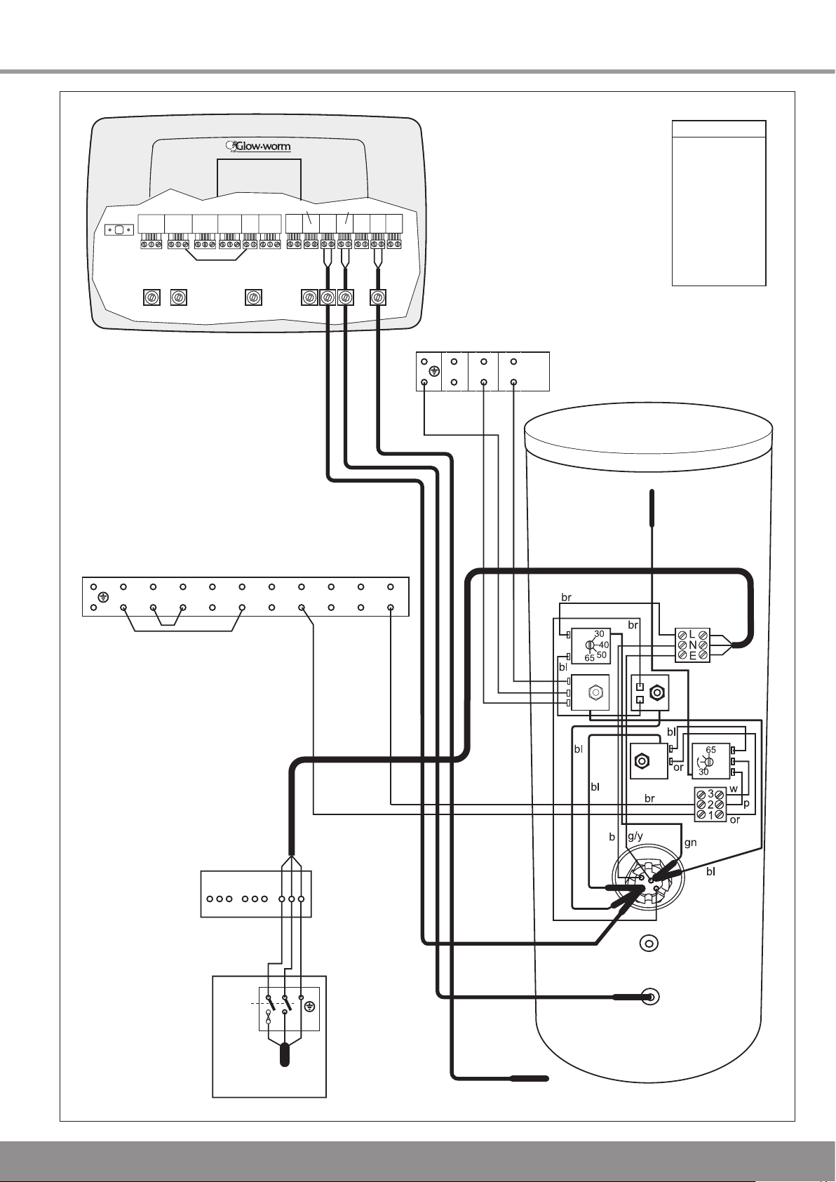
FLUROCYL
COMMON 230V
MAINS TERMINAL BLOCK
E
TERMINAL BLOCK
230V~50Hz
MAINS SUPPLY
L
N
E
Double
pole
isolator
RETURN PIPE
AT 3A
FUSED
AT 3A
ENL E N 21L
br
blg/y
N L 3 4 5 6 7 8 9
LINKE N L
10
ADDITIONAL
TERMINAL
BLOCK
FLUROPRO
CONTROLLER
230v~ PCSA
NTCA
TAC1
TAC2
GAINR
L
BROWN br
BLUE b
BLACK bl
ORANGE or
WHITE w
PURPLE p
GREEN gn
GREY g
GREEN
/YELLOW g/y
KEY
bl
2 Installation
14238
Wiring diagram
17
Diagram 2.10
Page 18

3 Commissioning
‘A’ PORT‘B’ PORT
BA
LEVER
3.1 Filling the secondary circuit
IMPORTANT: Risk of damage! Do not manually open the
temperature/pressure relief valve or the expansion vessel for
venting purposes. Any foreign matter in the pipework may
cause damage to the valve seats.
Make sure the cylinder drain valve is closed.
Open all cold and hot water taps and the corresponding
outlets.
Open the mains water supply to the Flurocyl and ll it with
water until it ows freely out of the outlets. Make sure all air
bubbles have been removed.
Close the outlets and check the system for leaks. Check in
particular the immersion heater connection for leaks.
The system must now be ushed thoroughly.
Open the hot water taps at the opposite ends of the systems
and let the water ow out for at least 5 minutes.
Close the hot water taps.
3.2 Setting the thermostatic mixing valve
The hot water from the solar cylinder can be set to a desired
maximum temperature between 30 °C and 70 °C by mixing
hot and cold water.
Set the hot water thermostatic mixing valve with the adjusting
knob to maintain the householders desired temperature at the
hot water taps.
IMPORTANT: Risk of being scalded by hot water! Set the
thermostat mixer to 60 °C or below and check the temperature
at a hot water tap to ensure effective protection against
scalding.
3.3 Reheat circuit (boiler circuit)
NOTE: Do not use the pressure relief valve of the boiler (if
applicable) for bleeding.
Flush the entire primary central heating system with cold and
hot water. Fill and bleed the central heating system according
to the installation manual of the boiler.
Set the lever on the motorised 2 port valve to MANUAL and
lock it in this position, see diagram 3.1.
Fill and bleed the central heating system after draining it
completely.
Unlock the lever on the motorised 2 port valve by setting it
back to AUTO.
Start up the boiler, refer to section 3.4, until the solar cylinder
is at operating temperature and all radiators in the system
are warm. Then drain the entire central heating system again
to remove any residue from the pipes. Fill and bleed it again
afterwards as described above.
3.4 Starting up the boiler
Switch on the main switch of the boiler.
Make sure the control device and the thermostats are set in
such a way that heating is necessary.
Check whether the boiler starts up and the water in the solar
cylinder and radiators is heated up according to the hot water
and room thermostat settings.
Perform the commissioning and testing procedures in
accordance with the installation manual for the boiler.
Motorised 2 port valve
GB: It is a requirement that the “Benchmark” Installation,
Commissioning and Service Record is completed and left with
the user.
IE: it is necessary to complete a “Declaration of Conformity” to
indicate compliance to I.S.813. An example of this is given in
the current edition of I.S.813.
Diagram 3.1
3.5 Handing over to the householder
l Hand over all manuals to the householder.
l Advise the householder to keep the manuals near to the
system.
l Draw special attention to the safety instructions which the
householder must follow.
l Review the user instructions with the householder and
answer any questions.
l Show the householder how to operate the solar control, CH
control and any separate DHW control.
l Inform the householder that the cylinder temperature is
factory set at 65°C and that the DHW temperature can be
adjusted using the TMV by the installer.
l Inform the householder that the immersion heater is
intended as a standby device and should not be used
simultaneously with the boiler to heat the cylinder.
l Inform the householder that they are not permitted to
change the settings made on the solar system.
l Inform the householder that to ensure the continued
efficient and safe operation of the solar system it is
recommended that it is checked and serviced at regular
intervals. The frequency of servicing will depend upon the
installation conditions and usage, but in general, once a year
should be enough.
lInform the householder that the boiler and solar cylinder
should be serviced by a qualied engineer annually.
Leave these instructions and the “Benchmark” Installation,
Commissioning and Service record document with the user.
14184
18
Page 19

4 Inspection and Maintenance
4.1 Checking the temperature / pressure relief
valve and expansion relief valve
Actuate each valve manually by turning the valve cap and
check whether the water ows unhindered to the discharge
point via the tundish. Make sure both valves t properly in idle
position.
4.2 Checking the charge pressure of the
expansion vessel
Block the water supply and open the nearest hot water tap to
reduce the pressure from the secondary water system.
Check the pressure of the expansion vessel at the
measurement point with a pressure gauge. If the pressure
is below 3.0 bar, increase it with an appropriate air pressure
pump.
NOTE: Only use original spare parts from Glow-worm for the
replacement of parts.
4.3 Maintenance Checklist
Reheating
Check the circulation pump annually.
Check the timer/time programme settings annually.
Reheating: does it deliver the desired deactivation
temperature? annually.
Solar cylinder
Bleed the heat exchanger if necessary annually.
Check the connections for leaks annually.
Check the temperature and pressure relief valve annually.
Checking the expansion relief valve annually.
19
Page 20
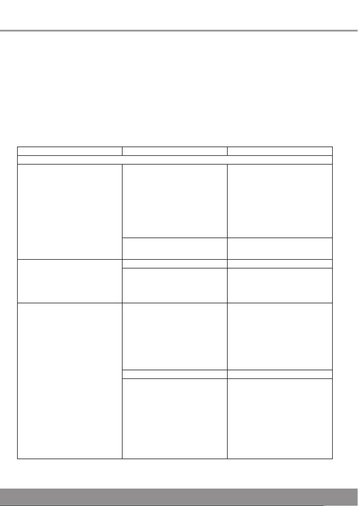
5 Fault Finding
The following tables provide information on possible
malfunctions during the operation of the solar cylinder as well
as their cause and remedy.
NOTE: Only use original spare parts from Glow-worm. for the
replacement of parts. We recommend making a maintenance
agreement.
Malfunction Cause Remedy
Solar cylinder
The cylinder cools down at night. The
ow and return temperatures vary after
switching off the pump. The collector
temperature is higher than the air
temperature at night.
Reheating is not working. The boiler
runs for a short time, goes off and then
back on again. This is repeated until the
cylinder is at its target temperature.
Only cold or lukewarm water comes out
of the taps.
1. The gravity brake is blocked. 1. Check the position of the blue handle.
2. Check the gravity brake for tightness
(jammed cuttings, particles of dirt in the
sealing face).
3. Do not connect the solar heat
exchanger directly, rather pull the supply
pipes downwards and then upwards to
the collector (syphon supports the gravity
brake) or install a 2-port valve, which
is switched on at the same time as the
pump.
2. One-pipe circulation in the event of
short pipe networks with low pressure
loss.
1. Air in the reheating heat exchanger. Bleed the reheating heat exchanger.
2. Heat exchanger surface area too small.
1. Cold and hot water connections on the
cylinder have been mixed up.
2. Hot water thermostat mixer set too low.
3. Solar heating insufcient; boiler does
not reheat.
External control device faulty.
Air in the reheating heat exchanger
Cylinder temperature sensor defective.
Install a gravity brake (as close as
possible to the cylinder).
Compare the specications of the boiler
manufacturer with those of the cylinder
manufacturer. The problem may be able
to be solved by a higher setting of the
ow temperature at the boiler.
Turn off the cold water supply, then
let water ow out via the hot water
connection. Only a few litres of water
ow out if the connection is laid correctly.
The inlet of the hot water draw-off pipe
then rests in the air space; no further
emptying is possible. If the entire solar
cylinder runs empty via the hot water
connection, the connections have been
laid incorrectly. Change the connections!
Increase the setting.
Check whether the boiler is working.
Check whether the external control
device is working.
Check whether the two port valve is in the
hot water position.
Replace the two port valve.
Bleed the reheating heat exchanger.
Check the thermal cut out and reset it.
Replace the cylinder thermostat.
Table 5.1 Fault Finding
20
Page 21
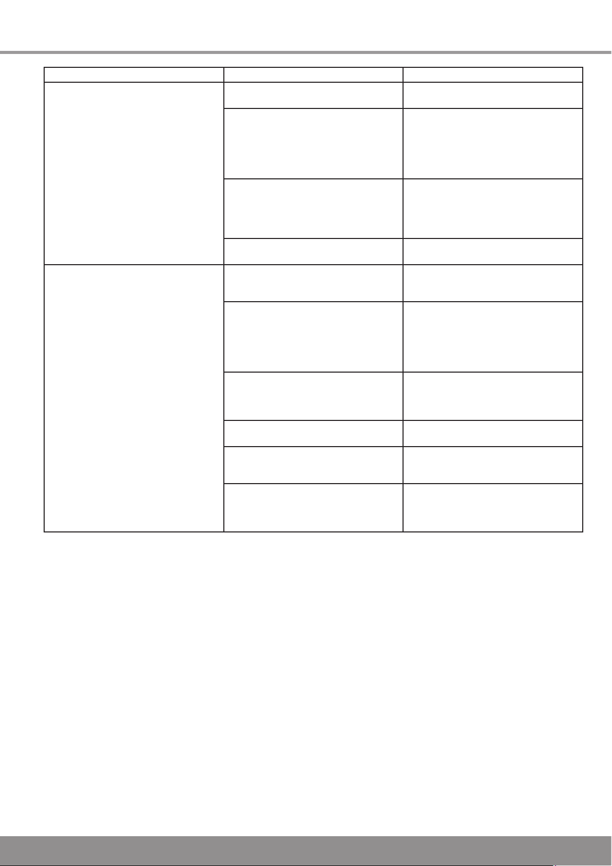
5 Fault Finding
Malfunction Cause Remedy
Water ows out of the expansion relief
valve (only when heating up).
Water comes out of the temperature and
pressure relief valve (only when heating
up).
Dirt on the valve seat of the expansion
relief valve.
Pressure limiting valve defective. Switch off the boiler and immersion
Expansion vessel defective. Check the pressure in the expansion
Expansion relief valve defective. If the pressure is normal, replace the
Dirt on the valve seat of the temperature
and pressure relief valve.
Temperature control of the boiler
defective.
Cylinder temperature sensor defective. Check the cylinder temperature sensor
Two port valve defective. Check whether the two port valve is
Temperature and pressure relief valve
defective.
Immersion heater defective. Check the temperature sensor of the
Check the expansion relief valve and
reset it manually.
heater and check whether the pressure
behind the pressure limiting valve is lower
than 3.0 bar if water ows out only when
heating up. If so, replace the pressure
limiting valve.
vessel. If the pressure is insufcient,
re-establish the pressure and check
whether the equalisation tank maintains
the pressure.
expansion relief valve.
Check the seat of the temperature
and pressure relief valve and reset it
manually.
Check the temperature control of the
boiler if water only comes out when
reheating with the boiler. Check whether
the two port valve switches to the heating
position after reaching the cylinder
temperature.
and the corresponding thermal cut outs
and replace the temperature sensor and
reset the thermal cut outs if necessary.
working and replace it if necessary.
Replace the temperature and pressure
relief valve if water only comes out when
heating up with the immersion heater.
immersion heater and the corresponding
thermal cut out and replace the
immersion heater if necessary.
Table 5.1 Fault Finding (continued)
21
Page 22

222324
Page 23

Page 24

Glow-worm, Nottingham Road, Belper, Derbyshire. DE56 1JT
0020055006
Because of our constant endeavour for improvement, details may vary slightly from those shown in these instructions.
0020055006-02 07.07
 Loading...