

Page 1

Instructions for Use
Installation and Servicing
To be left with the user
XTRAMAX
G.C. No. 47-047-15
Unvented Hot Water Storage
Fanned Flue Combination Boiler
4000116705-2.10.02
9088
This is a Cat II
The instructions consist of three parts, User, Installation and Servicing Instructions, which include the Guarantee Registration Card.
The instructions are an integral part of the appliance and must, to comply with the current issue of the Gas Safety (Installation and Use)
Regulations, be handed to the user on completion of the installation.
Appliance
2H3+
Guarantee Registration
Thank you for installing a new Glow-worm appliance in your home.
Glow-worm appliances' are manufactured to the very highest standard so we are pleased to offer our customers' a
Comprehensive Guarantee.
This product is guaranteed for 24 months from the date of installation or 30 months from the date of manufacture, whichever
is the shorter, for parts. In addition this product is guaranteed for 12 months from the date of installation or 18 months from
the date of manufacture, whichever is shorter, for labour.
The second year of the parts guarantee, from the beginning of the 13th month onwards after installation, is conditional upon
the boiler having been serviced by a CORGI registered gas installer, in accordance with the manufacturer's
recommendations. We strongly recommend regular servicing of your gas appliance, but where the condition is not met, any
chargeable spare parts or components issued within the applicable guarantee period still benefit from a 12 month warranty
from the date of issue from the manufacturer.
We recommend you complete and return as soon as possible your guarantee registration return literature, supplied in the
document envelope.
If your guarantee registration return literature is missing you can obtain a copy by telephoning the Heatcall Customer Service
number 01773 828100.
REGISTER YOUR GLOW-WORM APPLIANCE
CALL 0208 247 9857
Hepworth Heating Ltd.,
Nottingham Road, Belper, Derbyshire. DE56 1JT
General/Sales enquiries:
Tel: (01773) 824141 Fax: (01773) 820569
Page 2

Contents
CONTENTS DESCRIPTION SECTION PAGE No.
Important Information 3
INSTRUCTION
FOR USE
INSTALLATION
INSTRUCTIONS
Appliance Introduction 4
Appliance Safety Devices 5
Service and Maintenance 5
Operating the Appliance 6
Xtracom Remote Control 8
Technical Data 1 9
General Information 2 10
Heating System Design 3 11
Domestic Hot Water System Design 4 12
Boiler Schematic 5 12
Boiler Location, Flue and Ventilation 6 13
Safety Discharge 7 15
Fixing Jig 8 15
Piping System Installation 9 16
Boiler Installation 10 18
Horizontal Telescopic Top Flue Installation 11 19
Horizontal Top Flue Installation 11a 20
Electrical Connection 12 22
Commissioning 13 23
Safety Devices 14 26
Changing Gas Type 15 27
Settings 16 27
SERVICING
INSTRUCTIONS
Routine Cleaning and Inspection 17 28
Fault Finding 18 31
Replacement of Parts 19 33
Wiring Diagram 20 34
Spare Parts 21 44
4000116705-2
2
Page 3

Important Information
Gas safety (Installation and use) Regulations
In your interests and that of gas safety, it is the law that ALL gas
appliances are installed and serviced by a competent person in
accordance with the above regulations.
Testing and Certification
This boiler is tested and certificated for safety and
performance. It is therefore important that no alteration is
made to the boiler, without permission, in writing, from
Hepworth Heating Ltd.
Any alteration not approved by Hepworth Heating Ltd., could
invalidate the certification, boiler warranty and may also
infringe the current issue of the Statutory Requirements. The
requirements are: The installation of this boiler must be
carried out by a competent person in accordance with the
current rules in force in the countries of destination at the
time of installation. Manufacture's instructions supplied.
Manufacture's instructions must not be taken as overriding
statutory requirements.
Mandatory WARNING for EEC countries
This appliance is designed, approved and inspected to meet
the requirements of the Intended market. The data label
indicates where the product was manufactured and the
country for which it is intended.
CE Mark
This boiler meets the requirements of Statutory Instrument
No. 3083 The boiler (Efficiency) Regulations, and therefore
is deemed to meet the requirements of Directive 92/42/EEC
on the efficiency requirements for new hot water boilers fired
with liquid or gaseous fuels.
Type test for purposes of Regulation 5 certified by: Notified
body 0086.
Product/production certified by: Notified body 0086.
The CE mark on this appliance shows compliance with:
1. Directive 90/396/EEC on the approximation of the laws of
the Member States relating to appliances burning
gaseous fuels.
2. Directive 73/23/EEC on the harmonization of the Laws of
the Member States relating to the electrical equipment
designed for use within certain voltage limits.
3. Directive 89/336/EEC on the approximation of the Laws of
the Member States relating to electromagnetic compatibility.
Control of Substances Hazardous to Health
The adhesives and sealants used in this appliance are cured
and give no known hazard in this state.
INSULATION PADS/CERAMIC FIBRE
These can cause irritation to skin, eyes and the respiratory
tract.
If you have a history of skin complaint you may be susceptible to irritation. High dust levels are usual only if the material
is broken.
Normal handling should not cause discomfort, but follow
normal good hygiene and wash your hands before eating,
drinking or going to the lavatory.
If you do suffer irritation to the eyes or severe irritation to the
skin seek medical attention.
The insulation is composed of non-combustible material.
Electrical Supply
WARNING: This boiler must be earthed.
All system components shall be of an approved type and shall
be connected in accordance with the current issue of BS7671
and any applicable local regulations.
All external wiring between the appliance and the electrical
supply and earthing requirements shall comply with the current
IEE Regulations.
Connection of the boiler and system controls to the mains
supply must be through a common isolator and must be fused
3A, maximum. This method of connection must be by a fused
double pole isolating switch, with a minimum contact separation
of 3mm on both poles. The switch should be readily accessible
and preferably adjacent to the appliance. It should supply the
appliance only and be easily identifiable as so doing.
Alternatively, an unswitched shuttered socket outlet and 3A
fused 3 pin plug, both to the current issue of BS1363 may be
used provided that they are not used in a room containing a bath
or shower.
Wiring to the boiler must be PVC 85oC insulated cable, not less
than 0.75mm2 (24/0.20mm).
Manual Handling Guidance
During the appliance installation it will be necessary to employ
caution and assistance whilst lifting as the appliance exceeds
the recommended weight for a one man lift.
In certain situations it may be required to use a mechanical
handling aid.
Take care to avoid trip hazards, slippery or wet surfaces.
Spare Parts
REMEMBER, When replacing a part on this appliance, use only
spare parts that you can be assured conform to the safety and
performance specification that we require. Do not use
reconditioned or copy parts that have not been clearly authorised
by Hepworth Heating Ltd.
3
4000116705-2
Page 4

Important Information
Heating System Controls
The heating system must be controlled as described in the
relevant part of the current issue of :
Building Regulations, approved document L1, and the
references:
1) GIL 59, 2000: Central heating system specification (CheSS)
and
2) GPG 302, 2001: Controls for domestic central heating
system and hot water. BRECSU.
3) The domestic heating and hot water guide to the building
regulations 2001.
Thermostatic radiator valves may be installed, however they
must not be fitted in a room where the room thermostat is
located.
Gas leak or fault
If a gas leak or fault exists or is suspected, turn the boiler off and
consult the local gas supply company or your installation/
service company.
Air in the heating system
Persistent air in the heating system may indicate leaks in the
system or corrosion taking place. Call your Installation/Servicing
company.
Draining and filling
Caution: The boiler is installed as part of a sealed system which
must only be drained and filled by a competent person.
If the boiler is to be out of use for any long periods during severe
weather conditions, it is recommended that the whole system,
including the boiler, be drained to avoid the risk of freezing.
If in doubt, consult your servicing company.
Protection Against Freezing
The appliance has a built in frost protection programme as long
as the electricity and gas are left switched on.
This device operates the burner and system pump when the
temperature inside the boiler falls below 6
Any other exposed areas of the system should be protected by
a separate frost thermostat.
If the mains electricity and gas are to be turned off for any long
periods during severe weather, it is recommended that the
whole system, including the boiler, should be drained to avoid
the risk of freezing. Make sure that, if fitted, the immersion
heater in the cylinder is switched off.
If you have a sealed water system contact your installation/
servicing company as draining, refilling and pressurising MUST
be carried out by a competent person.
0
C.
Appliance Introduction
The XTRAMAX
boiler with electronic ignition providing central heating and
stored hot water.
The boiler is of the II
as distributed in the United Kingdom, or Butane (G30), Propane
(G31) with the appropriate conversion kit.
The boiler has a fan assisted balanced flue which both discharges
the products of combustion to and draws the combustion air
from the outside of the room.
The boiler is suitable for horizontal top outlet flue connection
and can be fitted with horizontal flue, vertical flue or twin-pipe
flue. Refer to flue options guide for further information, this is
available from your nearest stockist.
Both the central heating and domestic hot water temperature
are user adjustable.
Domestic hot water demand always has priority over heating
demand.
The boiler is designed for use as part of a sealed water central
heating system with fully pumped circulation. The pump,
expansion vessel and associated safety devices are all fitted
within the boiler.
The boiler can be installed against either an external wall or on
an adjacent inside wall, that is, the flue system will pass directly
to the rear or to either side to the terminal fitted on the outside
wall face.
boiler is a wall mounted modulating combination
category for use with Natural Gas (G20)
2H3+
The installation of this boiler must be carried out by a competent
person in accordance with the rules in force in the countries of
destination.
Manufacturer’s instructions must not be taken as overriding
statutory requirements.
These instructions should be carefully followed for the safe and
economical use of your boiler.
Note: The boiler serial number is marked on the data label
attached to the rear of the control box. The 'Operating the
Appliance' section describes how to safely use the boiler.
Accessories
A range of accessories are available.
For further information contact your supplier.
Flue options
There are various flue systems to choose from, for detailed
information refer to flue options guide, which is available
from your nearest stockist.
4000116705-2
4
Page 5

Appliance Safety Devices
Air flow rate safety device
If the flue is obstructed, even partially, the built in safety system
will turn the boiler OFF, the fan will continue to run. The boiler
will be ready to operate when the fault has been cleared.
Overheating safety
In the event of the boiler overheating the safety devices will
cause a safety shutdown. If this happens, call your Installation/
Servicing company.
In case of power supply failure
The boiler no longer operates. As soon as power supply is
restored, the boiler will be automatically restarted.
Frost protection
The appliance has a built in frost protection device that protects
the boiler from freezing. With the gas and electric supplies ON
and irrespective of any room thermostat setting, the frost
protection device will light the boiler when the temperature of
the boiler water falls below 6°C.
When the temperature reaches 16°C, the boiler stops.
Any other exposed areas of the system should be protected by
a separate frost thermostat.
Heating safety valve
CAUTION: A heating safety valve with a discharge pipe is fitted
to this boiler.
The valve MUST NOT BE TOUCHED except by a qualified
registered person. If the valve discharges at any time, switch the
boiler off and isolate it from the electrical supply. Contact your
installation/service company.
Temperature pressure/ relief valve
CAUTION: A domestic hot water pressure relief valve, with a
discharge pipe is fitted to this boiler.
The valve MUST NOT BE TOUCHED except by a qualified
registered person. If the valve discharges at any time, switch the
boiler off and isolate it from the electrical supply. Contact your
installation/service company.
Service and Maintenance
Servicing and Maintenance
To ensure the continued efficient and safe operation of the
appliance it is recommended that it is checked and serviced as
necessary at regular intervals. The frequency of servicing will
depend upon the particular installation conditions and usage,
refer to guarantee registration on the front cover of this literature.
If this appliance is installed in a rented property there is a duty
of care imposed on the owner of the property by the current
issue of the Gas Safety (Installation and Use) Regulations,
Section 35.
Servicing/maintenance should be carried out by a competent
person in accordance with the rules in force in the countries of
destination.
To obtain service, please call your installer or Heatcall (Glowworm’s own service organisation) using the telephone number
on the front cover of this literature.
Please be advised that the ‘Benchmark’ logbook should be
completed by the installation engineer on completion of
commissioning and servicing.
All CORGI Registered Installers carry a CORGI ID card, and
have a registration number. Both should be recorded in your
benchmark Logbook. You can check your installer is CORGI
registered by calling CORGI direct on: 01256 372300.
Cleaning
WARNING: This appliance contains metal parts (components)
and care should be taken when handling and cleaning with
particular regard to edges of sheet metal parts to avoid any
possibility of personal injury.
The boiler casing can be cleaned with a damp cloth, followed by
a dry cloth to polish.
Do not use abrasive or solvent cleaners.
Boiler casing
CAUTION. Do not remove or adjust the casing in any way, as
incorrect fitting may result in faulty operation. If in doubt, consult
your installation/service company.
5
4000116705-2
Page 6
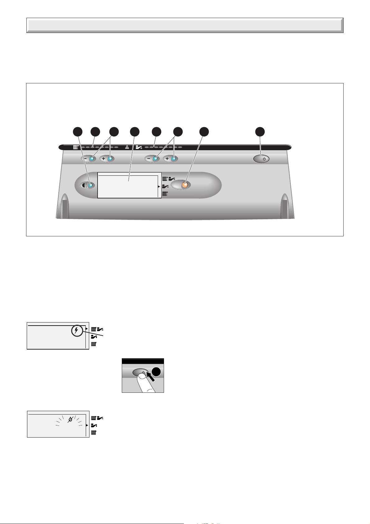
Operating the Appliance
Controls
The control panel, located at the lower front of the boiler casing,
see diagram 1, allows the boiler to be started, shut down,
controlled and monitored during use.
1 - On/Off button
2 - Summer/Winter mode selector
3 - Hot water temperature adjuster
4 - Hot water set point display (must be set at maximum)
mode
1.5 bar
The appliance incorporates a visual display that indicates fault
conditions, should they occur.
In the event of a fault, the display will indicate, by means of
pictograms and/or letters and numbers, exactly in which area
the fault lies.
Should the boiler fail to operate, the most likely fault is that the
gas supply to the boiler has not been turned on or that there is
no pressure in the heating system. These are indicated as
follows :
No gas supply
5 - Graphic display
6 - Heating temperature adjuster
7 - Heating set point display
8 - Display backlight
158 7 26 34
IO
9084
Diagram 1
This will be indicated on the
display as a pictogram of a
spark. To rectify this, proceed
as follows:
• Switch off the boiler at the On/Off
push button.
• Rectify the gas supply problem.
• Restart the boiler by pressing the
On/Off button.
IO
1
Insufficient system pressure
This will be indicated on the
display as a flashing warning
0.3
bar
indicating the system pressure
is low. To rectify this the system
must be re-filled, refer to
'Section 13 Commissioning'.
Other faults
These are indicated on the display by a fault code and a
telephone symbol. Further information on the fault codes can be
found in the 'Section 18 Fault Finding'.
4000116705-2
6
Page 7
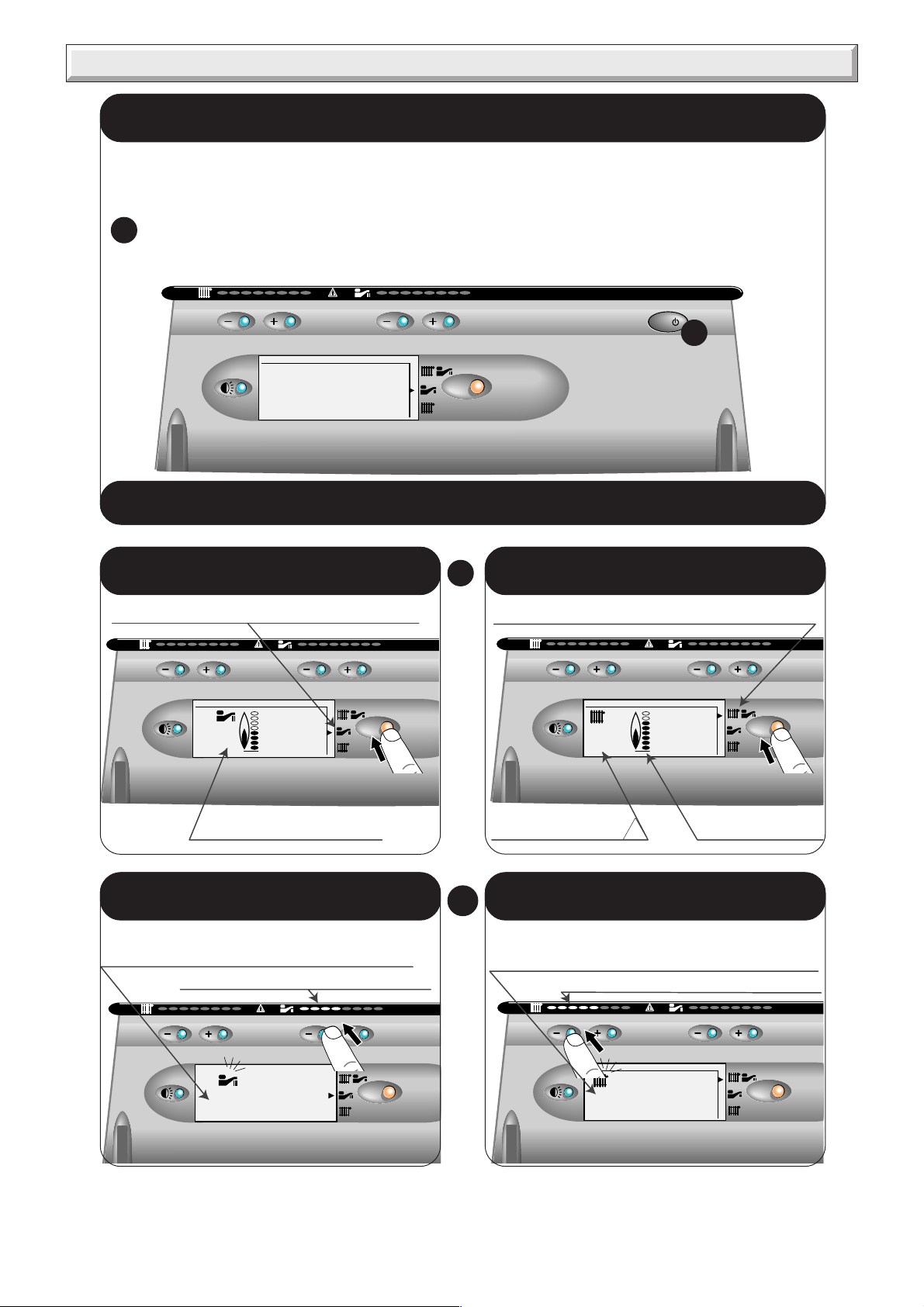
Operating the Appliance
Lighting the boiler :
Make sure that:
The boiler is connected to the electrical supply.
The gas service cock is open.
Then follow the instructions below :
Press the On/Off button (1)
1
The pressure must be between 1 and 2 bar. If not, the system must be filled by a competent person.
IO
1
mode
1.5 bar
To stop the boiler : Press button (1)
9087
Setting to the SUMMER position
(Hot water only)
Press the mode button to select the summer symbol
mode
1.5
bar
The flame symbol appears
when the boiler is running
Adjusting the hot water temperature
The domestic hot water must be set at max 60°C.
Press + or - to adjust the maximum temperature
of the hot water.
Visual indication of set temperature
Setting to the WINTER position
2
Press the mode button to select the winter symbol
The actual temperature
of the heating system
Adjusting the heating temperature
3
Press + or - to adjust the maximum temperature
of the heating (38°C to 87°C)
(Heating + hot water)
°C
10
Visual indication of set temperature
1.5
bar
Illuminates when
the boiler lights
mode
°C
50
To obtain domestic hot water, open a hot water tap. Hot water always has priority over central heating.
mode
7
60
°C
mode
4000116705-2
Hab261
Page 8
Xtracom Remote Control
Xtracom programmable, roomstat and boiler remote control
panel part No. A20077.
PROGRAMME/
THERMOSTAT
DISPLAY
REMOTE
CONTROL
DISPLAY
REMOTE
CONTROL OPTION
Diagram 2
Clock Timer and Thermostat Controls:
1 - Days of the week
2 - Override indicator
3 - Low Battery indicator
4 - Time display
5 - Heating in operation
6 - Programme temperature
7 - Room temperature
8 - Programme display
9 - Current programme status
10 - Override / Timed Override button
11 - OK/Enter button
12 - Plus and Minus modification buttons
13 - Manual programme setup buttons
14 - Time set button
15 - Temperature settings button
16 - Programme set button
17 - Cancel/Stand-by button
18 - Boiler Fault LED
2
1
3 4
6
5
7
Setting the Time
• Press button 14.
• Press + or - to set the correct hour.
• Press OK.
9091
• Press + or - to set the correct minutes.
• Press OK.
• Press + or - to set the correct day (1 = Mon. 7= Sun).
• Press OK, the clock will start.
Presetting the Temperatures T1, T2 and T3
The programmes use three temperature settings which you can
adjust.
Recommended first use settings are:-
T1=16°, T2=19°, T3=21°
If the radiators in your installation are equipped with thermostatic
valves, the highest temperature you can set on T3 is determined
by the highest setting on the radiator thermostatic valves.
e.g. If the highest radiator thermostat valve setting is 21°C then
you must set T3, 2 or 3°C higher, 24°C.
• Press button 15 T1 is displayed.
• Press + or - to set desired temperature.
• Press OK, T2 is displayed.
• Press + or - to set desired temperature.
• Press OK, T3 is displayed.
• Press + or - to set desired temperature.
• Press OK.
Weekly Programming
9328
9329
Diagram 4
9330
18
4000116705-2
18
14
17
15
10
16
13
12
9
8
Diagram 3
11
Diagram 5
There are 6 preset (P1 to P6) programmes and one manual (P=)
programme which can be assigned to each day of the week (1
to 7), the Factory default setting is P3 on all days. (Programmes
P1 to P6 can not be changed).
• Press button 16 to set day 1 (Monday).
• Press + or - to assign a programme to day 1.
• Press OK
8
Page 9

1 Technical Data
Heating
Heating input adjustable from 12,5 kW
to 30,3 kW
from 42,650 BTU/H
to 103,383 BTU/H
Heating output adjustable from 10,4 kW
to 27,6 kW
from 35,484 BTU/H
to 94,170 BTU/H
Efficiency 82 %
Maximum heating temperature 87 °C
Expansion vessel effective capacity 8 l
Expansion vessel charge pressure 0,5 bar
Maximum system capacity at 75°C 180 l
Safety valve, maximum service pressure 3 bar
Products outlet diameter 60 mm
Fresh air inlet diameter 100 mm
Hot water
Heating input adjustable from 12,5 kW
to 30,3 kW
from 42,650 BTU/H
to 103,383 BTU/H
Hot water output, automatically variable from 10,4 kW
to 27,6 kW
from 35,484 BTU/H
to 94,170 BTU/H
Storage capacity 43 l
Maximum hot water temperature 60 °C
Minimum hot water temperature 37°C
Specific flow rate (for 35°C temp rise) 11,4 l/min.
Threshold flow rate 1 l/min.
Nominal water flow rate 11,3 l/min.
Temp./pressure relief valve opening pressure 7 bar
Temp./pressure relief valve opening temperature 90°C
Cylinder heat up time 4 min.
Time to reheat 70% of storage to 60°C5 min.
Expansion valve setting 6 bar
Expansion vessel charge pressure 3.5 bar
Maximum operating pressure 3.5 bar
Maximum supply pressure 16 bar
Minimum operating pressure 0,7 bar
Natural Gas (G20)
Ø Burner injector 1,20 mm
Inlet pressure 20 mbar
Maxi. Burner pressure 13,8 mbar
Mini. Burner pressure 2,16 mbar
Gas rate maximum 3,20 m3/h
Gas rate minimum 1,32 m3/h
Butane Gas (G30)
Ø Burner injector 0,77 mm
Inlet pressure 29 mbar
Maxi. Burner pressure 23,8 mbar
Mini. Burner pressure 3,6 mbar
Gas rate maximum 2,39 kg/h
Gas rate minimum 0,99 kg/h
Propane Gas (G31)
Ø Burner injector 0,77 mm
Inlet pressure 37 mbar
Maxi. Burner pressure 30,8 mbar
Mini. Burner pressure 3,6 mbar
Gas rate maximum 2,35 kg/h
Gas rate minimum 0,97 kg/h
The Seasonal Efficiency Domestic Boilers UK (SEDBUK)
is, "D" 78.9%.
The value is used in the UK Government's Standard Assesment
Procedure (SAP) for energy rating of dwellings. The test data
from which it has been calculated have been certified by B.S.I.
131
234
Hab322
Weight of appliance when empty 71 kg
Weight of appliance when full 110 kg
Electrical
Electrical supply 230 V
Maximum absorbed power 235 W
Level of protection IP44
Fuse rating 3A
WEIGHT 71 kg
The
separate packages:
• The boiler
• The fixing jig
• The flue system
9
890
XTRAMAX
600
480
is delivered in three
Diagram 1.1
4000116705-2
Page 10

2 General Information
IMPORTANT NOTICE.
Where no British Standards exists, materials and equipment
should be fit for their purpose and of suitable quality and
workmanship.
Refer to Manual Handling Operations, 1992 regulations.
The installation of this boiler must be carried out by a competent
person in accordance with the rules in force in the countries of
destination.
Manufacturer’s instructions must not be taken as overriding
statutory requirements.
1.1 Sheet Metal Parts
WARNING: When installing the appliance, care should be
taken to avoid any possibility of personal injury when handling
sheet metal parts.
1.2 Statutory Requirements
The installation of the boiler MUST be carried out by a competent
person in accordance with the relevant requirements of the
current issue of:
Manufacturer’s instructions, supplied.
The Gas Safety (Installation and Use) Regulations, The Building
Regulations, The Building Standards (Scotland) Regulations
(applicable in Scotland), local Water Company Bylaws, The
Health and Safety at Work Act, Control of Substances Hazardous
to Health, The Electricity at Work Regulations and any applicable
local regulations.
Detailed recommendations are contained in the current issue of
the following British Standards and Codes of Practice, BS4814,
BS5440 Part 1 and 2, BS5449, BS5546, BS6700, BS6798,
BS6891 and BS7074 Part 1 and 2, BS7478, BS7593, BS7671.
Manufacturer’s notes must not be taken as overriding statutory
obligations.
BSI Certification
This boiler certificated to the current issue of EN 483 for
performance and safety.
It is important that no alteration is made to the boiler, without
permission, in writing, from Hepworth Heating Ltd.
Any alteration that is not approved by Hepworth Heating Ltd.,
could invalidate the warranty and could also infringe the current
issue of the Statutory Requirements.
1.3 Gas Supply
The gas installation must be in accordance with the current
issue of BS6891.
The supply from the governed meter must be of adequate size
to provide a steady inlet working pressure of 20mbar (8in wg) at
the boiler.
On completion, test the gas installation for soundness using the
pressure drop method and suitable leak detection fluid, purge
in accordance with the above standard.
3 Heating System Design
• The XTRAMAX is for use ONLY with sealed central heating
systems.
• Heating surfaces may consist of radiators, convectors or fan
assisted convectors.
• The appliance
system without the need for a mixing bottle. The maximum
central heating flow temperature can be set to 53°C on the boiler
printed circuit board during commissioning.
Bypass fully shut
1
Open 1/4 turn
2
3
Open 1/2 turn
Open 1 turn
4
Open 2 turns
5
can be piped directly to an underfloor heating
60
50
1
2
40
30
20
10
heating supply and return lines
Available pressure (kPa) between
0
(10 kPa = 1 m WG)
• Pipe sectional areas shall be determined in accordance with
normal practices, using the output/pressure curve
(diagram 3.1). The distribution system shall be calculated in
accordance with the output requirements of the actual system,
not the maximum output of the boiler. However, provision shall
be made to ensure sufficient flow so that the temperature
difference between the flow and return pipes be less than or
equal to 20°C. The minimum flow is 400 l/h.
3
4
5
120010008006004002000
Flow rate through heating system (I/h)
Diagram 3.1
Pom 010 a
4000116705-2
10
Page 11
SUPPLY
PIPE
AIR GAP
TUNDISH
CONTROL
VALVE
CONTROL
VALVE
TYPE CA BACKFLOW
PREVENTION DEVICE
BOILER
RETURN FLOW
HEATING
CIRCUIT
DRAIN
POINT
Method 2
3 Heating System Design
• The piping system shall be routed so as to avoid any air
pockets and facilitate permanent venting of the installation.
Bleed fittings must be provided at every high point of the system
and on all radiators.
• The total volume of water permitted for the heating system
depends, amongst other things, on the static head in the cold
condition. The expansion vessel on the boiler is pressurised at
0,5 bar (corresponding to a static head of 5 m w.g.) and allows
a maximum system volume of 160 litres for an average
temperature of 75°C and a maximum service pressure of 3 bar.
This pressure setting can be modified at commissioning stage
if the static head differs. An additional expansion vessel can be
fitted to the system if required, see diagram 9.2.
• Provision shall be made for a drain valve at the lowest point of
the system.
• Where thermostatic radiator valves are fitted, not all radiators
must be fitted with this type of valve, and in particular, where a
room thermostat is installed.
• In the case of an existing installation, it is ESSENTIAL that the
system is thoroughly flushed prior to installing the new boiler,
using a proprietary product such as Fernox or Sentinel. Contact
the product manufacturers for specific details.
3.1 Bypass
• The boiler is fitted with an adjustable automatic bypass.
Ensure that under no circumstances does the flow rate drop
below the figure specified, see diagram 3.1.
• A bypass is not required on the central heating circuit unless
the system controls could allow the boiler to operate when there
is no flow.
• Where a bypass has to be fitted, the bypass must be placed
at least 1.5 metres away from the appliance, see diagram 9.2.
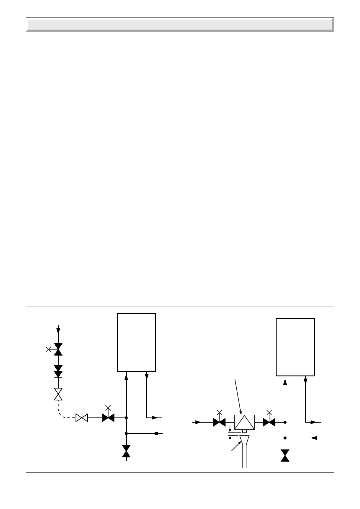
3.2 Filling the system
• Provision for filling the system must be made, the methods are
shown in diagram 3.2. There must be no permanent connection
to the mains water supply, even through a non-return valve.
Note: It is important that fittings used for connection to potable
water comply with the water undertakings requirements.
TEMPORARY
CONNECTION
Method 1
SUPPLY
PIPE
CONTROL
VALVE
HOSE
UNION
DOUBLE
CHECK
VALVE
HOSE
UNION
RETURN FLOW
CONTROL
VALVE
DRAIN
POINT
BOILER
HEATING
CIRCUIT
11
11594
Diagram 3.2
4000116705-2
Page 12
4 Domestic Hot Water System Design
• Copper tubing or plastic Hep20 may be used for the domestic
hot water system. Unnecessary pressure losses should be
avoided.
• A flow restrictor limiting the flow through the boiler to a
maximum of 16 l/min is fitted to the boiler.
• The boiler will operate with a minimum supply pressure of 0,7
bar, but under reduced flow rate.
Best operating comfort will be obtained from a supply pressure
of 1 bar.
4.1 Hard Water Areas
In areas where the water is 'hard', more than 200mg/litre, it is
recommended that a proprietary scale reducer is fitted in the
cold water supply to the boiler.
A pressure reducing valve for the cold water inlet supply is
provided, this is packed inside the boiler. This valve is a
necessary part of the unvented system and MUST be fitted to
the cold water supply, see diagram 8.1.
4.2 Domestic hot water drain point
The DHW drain point is located below the DHW pump, see
diagram 4.1.
9527
Diagram 4.1
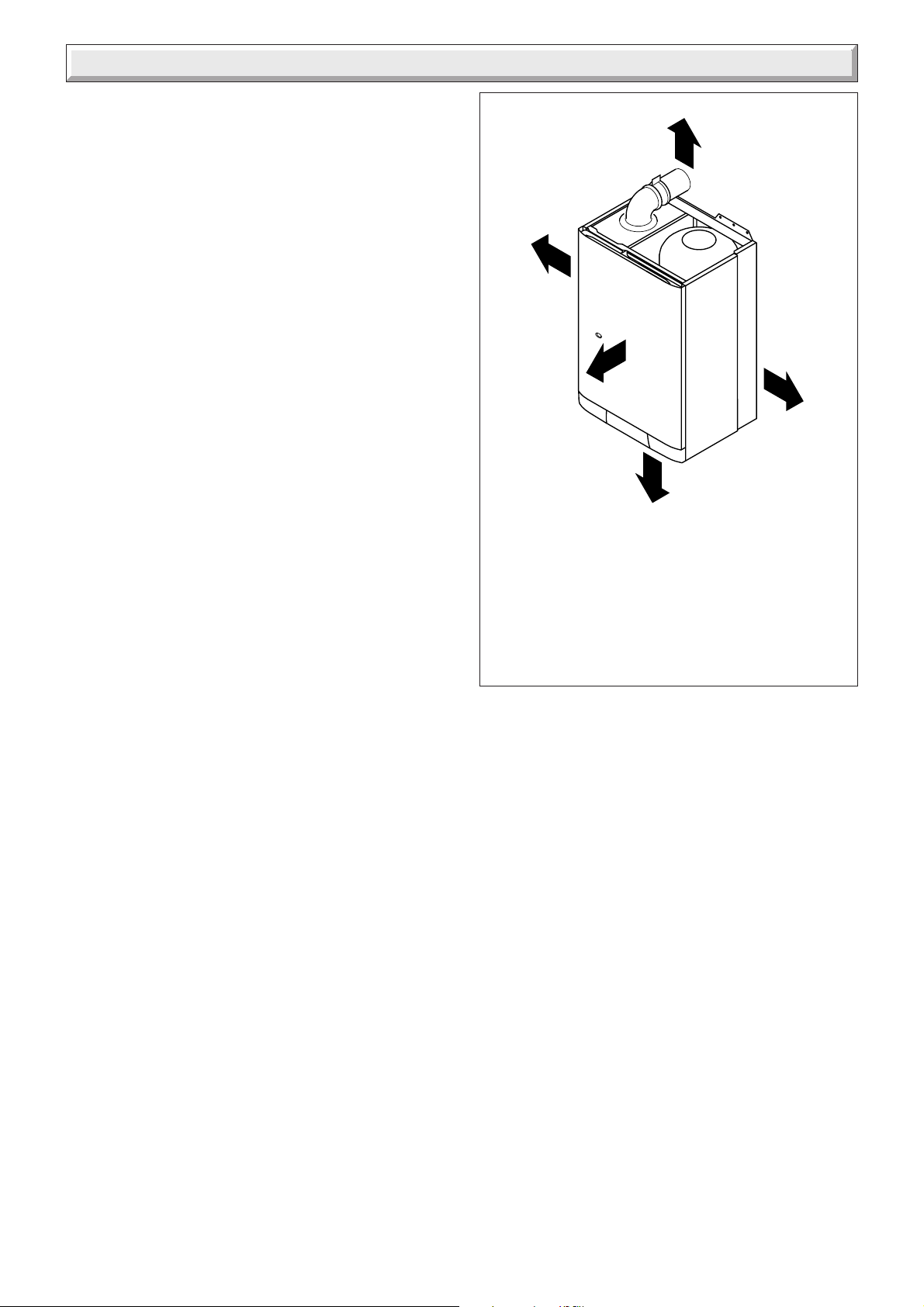
1 - Domestic thermistor
2 - Three way valve
3 - Gas control valve
4 - Ignition unit
5 - Temperature sensor for
DHW storage vessel
6 - DHW storage vessel
7 - Burner
8 - Ignition electrode
9 - Combustion chamber
10 - Heating safety valve (3 bar)
11 - Main heat exchanger
12 - Air pressure switch
13 - Water flow sensor
14 - DHW pump
15 - Non return valve
16 - Bypass
17 - Domestic plate to plate heat
exchanger
18 - Heating pump
19 - Heating expansion vessel
20 - Heating thermistor
21 - Overheat safety thermostat
22 - Flame sense electrode
23 - Fan
24 - Expansion valve (6 bar)
25 - Water pressure sensor
26 - Domestic expansion vessel (3.5
bar)
27 - Temperature pressure/ relief valve
(7 bar/90°C)
28 - Pressure reducing valve and
Check valve.
Max. supply pressure 16 bar.
(Supplied)
5 Boiler Schematic
21
19
COLD WATER
SUPPLY
28
A - Heating return
B - Cold water inlet
C - Heating flow
D - Domestic hot water outlet
22
18
17
15
25
AB
11
13
10
7
20
16
D1
23
12
27
9
8
4
3
1
2
14
C
E
D
E - Gas
D1 - Discharge from HTG
safety valves
D2 - Discharge from temp/press
and expansion valve (to tundish)
11749
6
5
26
24
D2
4000116705-2
Diagram 5.1
12
Page 13
6 Boiler Location, Flue and Ventilation
6.1 Boiler Location
The boiler may be installed in any room although particular
attention is drawn to the requirements of the current issue of
BS7671 with respect to the installation of a boiler in a room
containing a bath or a shower. Any electrical switch or boiler
control using mains electricity should be so situated that a
person using the bath or shower cannot touch it. The electrical
provisions of the Building Standards (Scotland) Regulations
are applicable to such installations in Scotland.
The boiler must be mounted on a flat wall, which is sufficiently
robust to take its total weight, see Technical Data.
If in doubt, expert advice should be obtained. In the event of the
wall being found not suitable, a floor standing kit is available,
contact Hepworth Heating for further details.
The boiler is not suitable for fitting outdoors.
Any electrical switch or boiler control using mains electricity
must be positioned so that a person using a bath or shower
cannot touch it.
6.2 Clearances
The position of the boiler must be such that there is adequate
space for servicing.
The recommended clearances are shown in diagram 6.1.
20mm
600mm
25mm
above
elbow
300mm
11771
20mm
6.3 Cupboard or compartment ventilation
The boiler can be fitted in a cupboard or compartment without
the need for permanent ventilation.
Important Note: With regards to the below boiler
dimension of 300mm, please ensure that the site
conditions will allow for the safety discharge pipe to
be installed, if not then the dimension should be
increased to 450mm.
MINIMUM CLEARANCES FROM A
PERMANENT SURFACE.
Diagram 6.1
13
4000116705-2
Page 14

6 Boiler Location, Flue and Ventilation
6.4 Terminal position
The minimum acceptable spacings from the terminal to
obstructions and ventilation openings are shown in diagram
6.2.
The boiler must be installed so that the terminal is exposed to
the external air.
Warning:
Do not obstruct the outside terminal of the boiler.
6.5 Terminal guard, see diagram 6.3
A terminal guard is required if persons could come into contact
with the terminal or the terminal could be subject to damage.
If a terminal guard is required, it must be positioned to provide
a minimum of 50mm clearance from any part of the terminal and
to be central over the terminal.
A suitable terminal guard type K3 can be supplied by:
Tower flue components Ltd.
Morley Road
Tonbridge
Kent
TN9 1RA
11508
6.6 Flue options
There are various flue systems to choose from as follows:
Horizontal telescopic top flue pack.
Horizontal top flue pack.
Horizontal extended flue pack.
Vertical flue pack.
Twin flue pack.
Extensions, 90° and 45° bends.
For detailed information refer to flue options guide. This is
available from your nearest stockist.
MINIMUM SITING DIMENSIONS FOR THE
POSITIONING OF FLUE TERMINALS MM
HORIZONTAL FLUES
A DIRECTLY BELOW, ABOVE OR
HORIZONTALLY TO AN OPENING, AIR BRICK,
OPENING WINDOWS, AIR VENT, OR ANY
OTHER VENTILATION OPENING 300
B BELOW GUTTER, DRAIN/SOIL PIPE 75
C BELOW EAVES 200
D BELOW A BALCONY OR CAR PORT 200
E FROM VERTICAL DRAIN PIPES AND
SOIL PIPES 150
F FROM INTERNAL/EXTERNAL CORNERS
OR TO A BOUNDARY ALONGSIDE THE
TERMINAL 300
G ABOVE ADJACENT GROUND OR
BALCONY LEVEL 300
H FROM SURFACE OR A BOUNDARY
FACING THE TERMINAL 600
I FACING TERMINALS 1200
J FROM OPENING (DOOR/WINDOW)
IN CAR PORT INTO DWELLING 1200
K VERTICAL FROM A TERMINAL 1500
L HORIZONTALLY FROM A TERMINAL 300
VERTICAL FLUES
M FROM ADJACENT WALL TO FLUE 300
N FROM ANOTHER TERMINAL 600
P FROM ADJACENT OPENING OR WINDOW 1000
Q ABOVE ROOF LEVEL 300
Diagram 6.2
4000116705-2
Diagram 6.3
14
Page 15

7 Safety Discharge
Valve outlet
size
G 1/2 15 mm 22mm up to 9 m 0.8 m
G 3/4 22 mm 28 mm up to 9 m 1.0 m
G 1 28 mm 35 mm up to 9 m 1.4 m
Safety
device eg.
temperature
relief valve
Discharge pipe (D2) from
turndish with continuous fall see table
above for size examples.
Minimum size of
discharge to tundish
D1
Discharge pipe (D1) from
temperature relief valve to turndish
500mm
max.
Tundish
(Supplied)
9317
Minimum size of discharge
pipe D2 from tundish
28 mm up to 18 m 1.0 m
35 mm up to 27 m 1.4 m
35 mm up to 18 m 1.4 m
42 mm up to 27 m 1.7 m
42 mm up to 18 m 1.7 m
54 mm up to 27 m 2.3 m
300mm min.
Fixed grating
Trapped
gully
Maximum resistance allowed
expressed as a length of straight
pipe i.e. no elbows or bends
Discharge from
HTG prv on jig
D1 D2
9317
Tundish
(Supplied)
9131
Discharge from
DHW safety
valves
Resistance created
by each elbow
or bend
Gully
9129
Diagram 7.1
8 Fixing Jig
The fixing jig is made up, from left to right, as follows:
A - Heating return fitting with isolating valve (v) and drain knob (u).
B - Cold water inlet fitting with isolating valve (m) and factory fitted flow restrictor and filter (not shown).
C - Heating flow fitting with isolating valve (q) drain knob (r) and safety valve (10).
D - Domestic hot water outlet.
E - Gas service cock.
(Fitted inside) Flow
restrictor and cold water
inlet filter
B
D
u
A
C
r
q
E
➜
m
➜
10
15
9126
Diagram 8.1
4000116705-2
v
Page 16

9 Piping System Installation
9.1 Fixing jig, refer to diagram 8.1
• Remove the contents of the fixing jig pack.
• Secure the left and right hand support brackets to the isolating
valve plate with the securing screws (4 off) supplied.
Connect the copper connections supplied, to the fixing jig
fittings.
• Heating system connections - Pipe Ø 22mm
• Hot water system connections - Pipe Ø 15mm
• Gas connection - Pipe Ø 22mm
• Tundish connection - Pipe Ø 22mm
• Safety valve discharge - Diagram 7.1.
9.2 Cutting the flue hole
• Remove the wall template, follow the instructions given on the
wall template.
• Determine the flue application, length and terminal position
before starting.
• Position the wall template, taking due regard of the minimum
clearances for the selected flue application, see diagram 9.1.
Rear hole cutting
• Mark correct position of top rear flue outlet hole from template.
Side hole cutting
• Mark the horizontal centre line for the hole on the rear wall.
Extend the horizontal centre line to the side wall and mark the
vertical centre line of flue hole as shown in diagram 9.1.
Important: When cutting the flue hole and when extending the
flue centre line to a side wall, remember that the flue system
must have a fall of about 35mm per metre of flue DOWNWARD
towards the terminal. There must NEVER be a downward
incline towards the boiler.
• Making allowance for the slope of the flue, cut hole in external
wall, preferably using a core drill. For installations with internal
and external access use a 105 mm diameter core drill.
For installations with internal access only use a 125 mm
diameter core drill.
• Reposition the wall template over hole in wall.
• Mark the position of the holes for the hanging bracket and jig.
• Drill, plug and fix the hanging bracket to the wall using suitable
screws (not supplied).
• Check that the hanging bracket is level.
• Drill plug and fix the fixing jig to the wall.
9.3 Water connection
Connect the system pipework to the copper connections on the
fixing jig observing the correct flow and return format as shown
in diagram 9.2. Do not subject the isolating valves to heat.
bottom of the boiler (diagram 5.1 and 7.1) (D2). The tundish
(supplied) must be used with this outlet within the normal
guidelines and code of practice and must be installed so that it
is visible to the occupants and positioned away from any
electrical devices.
It is necessary, during installation, to connect a 22 mm diameter
metal discharge pipe to a suitable position outside the building.
It is permissible to use copper pipe, see diagram 7.1.
WARNING. The discharge pipe from the tundish should
terminate in a safe place where there is no risk to persons in the
vicinity of the discharge, be of metal and:
a. Be at least one pipe size larger than the nominal outlet size
of the safety device unless its total equivalent hydraulic resistance
exceeds that of a straight pipe 9m long i.e. discharge pipes
between 9m and 18m equivalent resistance length should be at
least larger than the nominal outlet size of the safety device,
between 18m and 27m at least 3 sizes larger, and so on. Bends
must be taken in to account in calculating the flow resistance.
See table and diagram 7.1.
b. Have a vertical section of pipe at least 300mm long, below the
tundish before any elbows or bends in the pipework.
c. Be installed with a continuous fall.
d. Have discharges visible at both the tundish and the final point
of discharge but where this is not possible or practically difficult
there should be clear visibility at one or these of these locations.
Examples of acceptance discharge arrangements are:
1. ideally below a fixed grating and above the waterseal in a
trapped gully.
2. downward discharges at a low level; i.e. up to 100 mm above
external surfaces such as car parks, hard standing, grassed
areas etc. are acceptable providing that where children may
play or otherwise come in to contact with discharges, a wire
cage or similar guard is positioned to prevent contact, whilst
maintaining visibility.
3. discharges at high level; e.g. into metal hopper and metal
down pipe with the end of the discharge pipe clearly visible
(tundish visible or not) or onto a roof capable of withstanding
high temperature discharges of water and 3m from any plastics
guttering systems that would collect such discharges (tundish
visible).
4. where a single pipe serves a number of discharges, such as
in blocks of flats, the number served should be limited to not
more than 6 systems so that any installation can be traced
reasonably easily. The single common discharge pipe should
be least one pipe size larger than the largest individual discharge
pipe to be connected. If unvented hot water storage systems
are installed where discharges from safety devices may not be
apparent i.e. in dwellings occupied by blind, infirm or disabled
people, consideration should be given to the installation of an
electronically operated device to warn when discharge takes
place.
Note: The discharge will consist of scalding water and steam.
Asphalt, roofing felt and non-metallic rainwater goods may be
damaged by such discharges.
9.4 Safety valve discharge
There are two sets of two safety valves fitted to this appliance.
One is located on the jig diagram 8.1, (10) heating safety valve
3 bar. The other is located inside the boiler (diagram 5.1,) (27)
temperature pressure/relief safety valve 7 bar/90°C, and (24)
expansion valve 6 bar.
9.5 Tundish discharge
The internal safety valves, 24 and 27, have been tee’d together
and the discharge pipe run so that it exits at the right hand
4000116705-2
9.6 Domestic hot water supply options
The domestic hot water storage temperature inside the boiler
must be set 60° C. It is recommended that the boiler storage
temperature is set by the user to the maximum of 60°C - this will
ensure a more plentiful supply of hot water.
It may be desirable to provide hot water to separate outlets at
different temperatures (for example, to provide a limited
temperature to prevent the risk of scalding). To be able to do
this, a thermostatic mixing valve is supplied with the Xtramax
boiler (factory set to 43°C) and can be fitted during the installation
procedure.
16
Page 17

9 Piping System Installation
There are 2 options for the domestic hot water supply :
1 - Piping the hot water supply without the use of the mixing
valve to provide hot water to all taps at the same temperature.
2 - Piping the hot water supply using the mixing valve (supplied)
to provide hot water at boiler hot water “set temperature” to one
tap and thermostatically controlled hot water to another tap(s).
To pipe the hot water supply using the mixing valve, refer to
diagram 9.2. This shows one outlet supplying hot water at the
boiler hot water "set temperature" and one hot water outlet at
a temperature pre-set at the mixing valve. The mixing valve can
be set between 35 and 60°C. It is recommended that the valve
is adjusted (and locked) by the installer to the desired
temperature.
Note: The thermostatic mixing valve has 22 mm connections,
22x15 mm reducers will need to be fitted.
The connections to the mixing valve are :
H - Hot water supply from boiler
C - Reduced cold water supply
MIX - Thermostatically controlled outlet
Warning : It is strongly recommended that the cold water
supply to the mixing valve is taken from the reduced side of the
pressure reducing valve (supplied)
Note 1 : The mixing valve is fitted with two in-line strainers, one
on the hot inlet and one on the cold inlet. For servicing details
of these, refer to the separate instructions supplied with the
mixing valve.
Note 2 : The mixing valve incorporates a "rapid fail-safe" device
which will automatically close the valve to safety in the event of
supply failure on either hot or cold water.
• The supply from the governed gas meter must be of adequate
size to provide a constant inlet working pressure of 20 mbar (8
in w.g.).
To avoid low gas pressure problems, it is recommended that the
gas supply is connected using 22 mm pipe.
• On completion, the gas installation must be tested using the
pressure drop method and purged in accordance with the
current issue of BS6891.
Ø 105 or 125 core drill
169
65
=
=
234
20 mm
min.
900
9.7 Gas connection
Gas Safety (Installation and use) Regulations
In your interests and that of gas safety, it is the law that ALL gas
appliances are installed and serviced by a qualified registered
person in accordance with the above regulations.
Additional
expansion
vessel
(if required)
Return
Heating
circuit
control valve
Boiler
Bypass
valve
Filling
device
Flow
Drain point
Domestic
water
Hot
Cold supply
9090
Thermostatic
mixing valve
MIX
H
(supplied)
C
Temperature
adjustment
(supplied)
Pressure
reducing valve
and Check valve.
Max. supply pressure
16 bar.
(supplied)
120
600
Thermostatically
controlled
hot water
20
Diagram 9.1
9130
Boiler
"set temperature"
hot water
Diagram 9.2
17
4000116705-2
Page 18

10 Boiler Installation
10.1 Warning to the installer
This installation is subject to building regulation approval, notify
the Local Authority of intention to install.
10.2 Installing the boiler
Prior to starting work, the system must be thoroughly flushed
using a propriety cleanser such as Sentinel X300 to eliminate
any foreign matter and contamination e.g. metal filings, solder
particles, oil, grease etc.
Note. Solvent products could cause damage to the system.
• IMPORTANT: With regards to the manual handling operations,
1992 regulations, the following operation exceeds the
recommended weight for one man to lift.
• Lay boiler on its back.
• Remove all packaging from around the boiler.
• Remove front panel, put in a safe place to avoid damaging it.
• Ensure the plastic plugs are removed from water and gas
pipes. NOTE: There will be some spillage of water.
• Remove transportation timber support bar from bottom rear of
boiler.
• If required the boiler can be stood upright supported by
extending the legs at the front bottom of the boiler.
• Lift the boiler up and engage boiler upper part onto the hanging
bracket.
• Fit the washers between the boiler pipes and the inlet and
outlet fittings on the fixing jig and connect the various couplings
between the boiler and jig.
• Fit the base panel, hook in at the rear secure with the four self
tapping securing screws at the front.
4000116705-2
18
Page 19

11 Horizontal Telescopic Top Flue Installation
The
Horizontal Telescopic Top Flue,
A2004500 is suitable for installations that
require a flue length from 425 minimum to
659.5 maximum. If longer flueing is required
extensions and bends are available, see note
below.
Note: Additional 1 metre extentions, 90° and 45° bends are
available. The maximum extended flue is 3.5m. The use of flue
bends requires the flue lengths to be reduced by 1m. for 90° and
0.5m. for 45°.
Kit No.
A
10322
C
B
11.1 Horizontal Telescopic Top Flue kit of
parts, refer to diagram 11.1.
11.2 Installation of telescopic flue assembly
• Carefully pull to remove the elbow (D) from the air duct pipe
and flue duct pipe (A).
• Remove the backing from the self adhesive gasket (F) and
carefully fit gasket to base of flue elbow.
• Fit the restrictor (a) inside the fan outlet, see diagram 11.3.
• Fit elbow onto boiler and secure with the four screws (G).
• Fit rubber sealing collar (E), see diagram 11.2, into groove at
the outer end of the air duct pipe (A).
• Fit air/flue duct pipe assembly, into wall from the outside with
rubber sealing collar to the outside.
• Pull pipe assembly inwards to bring rubber sealing collar hard
up against external wall.
• If the telescopic flue has been pulled apart care must be taken
not to damage the ‘O’ ring on the flue duct when re-assembling.
• Re-fit the telescopic flue duct pipe to the flue elbow . Secure
with the fixing collar seal (B) and fixing collar (C) using the 2
screws provided.
G
D
E
F
The flue kit A2004500 is 659.5 mm long and comprises:
- Telescopic flue assembly......................................... A
- Fixing collar seal ...................................................... B
- Fixing collar .............................................................. C
- Elbow ....................................................................... D
- External rubber sealing collar .................................. E
- Gasket ...................................................................... F
- Screws .....................................................................G
Diagram 11.1Horizontal telescopic Top flue kit
Pho 087
Diagram 11.2
Horizontal telescopic flue
system (rear and side)
The maximum permissible
length (L) for the telescopic
flue system is 630mm.
The restrictor (a) must be
fitted to inside the fan outlet.
Gasket
a
19
L
65
234
9530
MINIMUM WALL
THICKNESS
192mm
Diagram 11.3
4000116705-2
Page 20

11a Horizontal Top Flue Installation
The
Horizontal Top Flue
suitable for installations that require a flue
length from 190 minimum to 667 maximum
(without extensions). If a shorter flue length is
required the flue can be cut to suit, see
diagrams 11a.1 and 11a.2 for minimum flue
length.
Note: Additional 1 metre extentions, 90° and 45° bends are
available. The maximum extended flue is 3.5m. The use of flue
bends requires the flue lengths to be reduced by 1m. for 90° and
0.5m. for 45°.
11a.1 Top outlet flue - kit 86285H
The boiler is only suitable for top outlet flue connection.
11a.2 Rear flue systems
(Refer to diagram 11a.1). To calculate the length when flueing
to the rear measure wall thickness e plus 140 mm for the outer
air duct and e plus 231 mm for the inner flue duct measurement.
11a.3 To The Right or Left flue systems
(Refer to diagram 11a.1). To calculate the length when flueing
For right hand applications measure wall thickness e plus
inside of wall to side of boiler a add 350(mm) for the outer air
duct and wall thickness e plus inside of wall to side of boiler a
add 445(mm) for the inner flue duct measurement.
(Refer to diagram 11a.1). To calculate the length when flueing
For left hand applications measure wall thickness e plus
inside of wall to side of boiler a minus 25(mm) for the outer air
duct and wall thickness e plus inside of wall to side of boiler a
add 70(mm) for the inner flue duct measurement.
• Refer to diagram 11a.2 (table) for cutting lengths of both inner
and outer flue pipes for each of the various flue options
available.
Important: All flue cutting lengths must be measured from the
terminal end of the flue pipes, see diagram 11a.2.
When the dimension X measured on site is greater than that
given in diagram 11a.2 (table), extensions will be required as
necessary.
Important: All cutting lengths should be measured from the
push fit joint end of the extension pipe. Do not leave any burrs
or sharp edges on the cut ends of the pipes. Note : maximum
horizontal flue length without bends is 3 m.
, Kit No. 86285H is
70mm 70mm
a
X
a
X
Diagram 11a.1
ee
9322
Ven 089
4000116705-2
AIR DUCT PIPE
Cutting length
FLUE DUCT PIPE
Cutting length
11a.2 Table: Flue cutting lengths (mm)
Rear flue
Air Duct pipe : e + 55, Flue duct pipe : e + 217
Note : maximum distance 'x' without extension 770 mm
Right side flue
Air Duct pipe : e + a + 290, Flue duct pipe : e + a + 452
Note : maximum distance 'x' without extension 515 mm
Left side flue
Air Duct pipe : e + a - 48, Flue duct pipe : e + a + 114
Note : maximum distance 'x' without extension 1087 mm
Diagram 11a.2
20
Page 21

11a Horizontal Top Flue Installation
11a.4 Installation of flue assembly
Important: If the flue has been cut, ensure that there are no
burrs that could damage the ‘O’ ring.
• For flue systems less than 0,5 m long, leave the restrictor (a)
fitted in the fan outlet, see diagram 11a.5.
• Remove the backing from the self adhesive gasket (H) and
carefully fit gasket to base of elbow (C).
• Fit both ‘O’ rings (J) into the flue elbow (C), one at the inlet, one
at the outlet. By necessity, they are a loose fit, apply a small
amount of silicone grease to each ‘O’ ring when fitting.
• Fit elbow onto boiler and secure with the four screws (I).
• Fit rubber sealing collar (F), see diagram 11a.3, into groove
at the outer end of pipe (A).
• Insert flue duct pipe (B) into inner end of air duct pipe (A), rotate
flue duct pipe to locate into groove inside air duct pipe.
• Fit air/flue duct pipe assembly into wall from outside with
rubber sealing collar to the outside.
• Fit internal plastic flange (G) onto air duct pipe (A).
• Fit the fixing collar seal (D) onto the air duct pipe (A) ensuring
it is the correct way round (the larger diameter onto the pipe).
• Pull air/flue duct pipe assembly inwards to bring rubber sealing
collar (F) hard up against external wall, while carefully pushing
the fixing collar seal onto the elbow ensuring that the flue duct
pipe locates into the flue elbow outlet while taking care not to
tear the ‘O’ ring.
• Fit the fixing collar (E) around the fixing collar seal (D) and
secure with 2 screws provided.
• Push the internal plastic flange (G) along the air duct pipe (A)
until engaged against internal wall.
G
F
B
E
A
J
H
The flue kit 86285H is 810mm long and comprises:
- Air duct pipe .......................................................... A
- Flue duct pipe ........................................................ B
- Elbow ....................................................................... C
- Fixing collar seal .................................................... D
- Fixing collar .............................................................. E
- External rubber sealing collar ............................... F
- Internal flange ....................................................... G
- Gasket ..................................................................... H
- Screws ....................................................................... I
- 'O' rings ..................................................................... J
Diagram 11a.3
D
11646
C
I
Pho 087
Concentric flue system
The maximum permissible length (L) for
the concentric flue system is 3.5 m. For
flue systems up to 0,5 m length, the
restrictor (a) supplied fitted to the boiler,
inside the fan outlet, must be left in
place. For longer flue systems, the
restrictor must be removed.
For each 90° flue elbow used, (or two
45° elbows) the maximum permissible
length (L) must be reduced by 1 metre.
Gasket
a
L
65
234
Diagram 11a.4
9530
WALL
THICKNESS
21
Diagram 11a.5
4000116705-2
Page 22

12 Electrical Connection
WARNING: This appliance must be earthed and must be wired
in accordance with these instructions. Any fault arising from
incorrect wiring cannot be put right under the terms of the Glow-
worm guarantee.
All system components must be of an approved type.
Electrical components have been tested to meet the equivalent
requirements of the BEAB.
The mains electrical supply must be maintained at all times in
order to provide domestic hot water.
Do not interrupt the mains supply with a time switch or
programmer.
Connection of the whole electrical system and any heating
system controls to the electrical supply must be through a
common isolator.
Isolation should preferably be by a double pole switched fused
spur box fused at 3A having a minimum contact separation of
3mm on each pole. The fused spur box should be readily
accessible and preferably adjacent to the boiler. It should be
identified as to its use.
A three pin plug fused at 3A and shuttered socket outlet may be
used instead of a fused spur box provided that:
a) They are not used in a room containing a fixed bath or
shower.
b) Both the plug and socket comply with the current issue of
BS1363.
12.1 Mains Cable
The boiler is supplied with a mains lead attached, see diagram
12.1.
Standard colours are Brown - Live, Blue - Neutral, Green and
Yellow - Earth.
Important: If a replacement supply cable is required it must be
purchased. Part No. S1008600.
3. Test the polarity of the mains.
Please ensure the “Benchmark” logbook is completed and left
with the user.
Note: For further information, see the building regulations
1991 - Conservation of Fuel and Power - 1995 edition appendix G, Table 4b.
The boiler is supplied with a mains lead attached.
Connect this to the electrical supply.
Ins 060
Diagram 12.1
IMPORTANT
With VOLTAGE FREE
10023
room thermostat
°C
Without room
thermostat
EE
12.2 External controls
WARNING: UNDER NO CIRCUMSTANCES MUST ANY
MAINS VOLTAGE BE APPLIED TO ANY OF THE TERMINALS
ON THE HEATING CONTROLS CONNECTION PLUG.
To gain access to the external control connections, unclip side
clips and hinge up control panel cover.
The boiler will work for heating without a room thermostat being
connected provided that the wire link fitted between the two
terminals of the connector (E) is left in place, see diagrams
12.2 and 12.3.
Alternatively, a 24V room thermostat can be used but do not
make any connection to the compensating resistor, see diagram
12.2.
ON NO ACCOUNT must any electrical voltage be applied to
any of the terminals of the external controls plug.
12.3 Remote control (F)
For extra control or if the boiler is to be sited in a garage or utility
room an optional remote control unit with programmable roomstat
can be obtained part number A20077, see diagram 2. This is
a dual function unit, (a) boiler control (same as boiler facia), (b)
programmable room stat. Full fitting instructions are supplied
with the unit.
12.4 Electrical Connections - Testing
Checks to ensure electrical safety must be carried out by a
competent person.
After installation of the system, preliminary electrical system
checks as below should be carried out.
1. Test insulation resistance to earth of mains cables.
2. Test earth continuity and short circuit of all cables.
Diagram 12.2
Leave link in place for no external controls.
No room thermostat.
Leave link in place
Heating controls
connection plug
E
IMPORTANT
VOLTAGE FREE
room thermostat.
Remove link and connect
to terminals 1 and 2 ONLY,
F
Note: Connection F i s
used when the optional
remote control with room
thermostat Part No.
A20077 is fitted.
DO NOT connect to
terminal 3
Diagram 12.3
11751
4000116705-2
22
Page 23

13 Commissioning
Please ensure the “Benchmark” logbook is completed and left
with the user.
The commissioning and first firing of the boiler must only be
done by a competent person.
Gas installation
It is recommended that any air is purged from the supply at the
gas inlet test point on the gas valve, see diagram 13.1.
Filling the system 1 to 8
Air in pipes
Important: A central heating system can not operate correctly
unless it is filled with water and air bled from the system. If these
conditions are not met the system may be noisy.
Bleed the air in the radiators and adjust the pressure if system
requires. If the system requires filling too often this may be due
to minor leaks or corrosion in the system. Call a qualified service
engineer.
GAS INLET
TEST POINT
11752
Press the mains 'On/Off' button
1
The warning light will illuminate
➜
v
The display will indicate 0 bar pressure in the system
mode
0.0
bar
9126
q
3
Undo cap on
automatic air
vent on top of
pump and
leave undone.
Diagram 13.1
9086
IO
1
Open the boiler isolating valves (v and q),
2
the slot of the screw corresponds to flow
direction.
23
Reg 008
4000116705-2
Page 24

13 Commissioning
o
Open the system filling loop and fill the
4
system until the pressure indicated
on the display is between 1 and 2 bar.
Bleed each radiator to
5
remove the air, re-tighten
bleed screws.
➜
9621
Leave the cap on the
6
pump auto air vent open.
➜
The pressure must be between 1 and 2 bar
1.5
bar
Open various hot water
7
taps to bleed system.
m
Ins 061a
Make sure the display indicates a system pressure of between 1 and 2 bar. Re-fill
8
system as necessary.
The pressure must be between 1 and 2 bar
• Adjust heating temperature to maximum .
• Check that any external controls, if fitted, are calling for heat
(set room thermostat to maximum).
• Allow the temperature to rise to the maximum value, with all
radiator valves open. The temperature rise will cause release of
the gases contained in the water of the central heating system.
• Gases driven towards the boiler will be automatically released
through the automatic air vent.
• The gases trapped at the highest point of the system must be
released by bleeding the radiators. Check the burner gas rate
required, ten minutes from lighting. Refer to Data Label on
electrical controls box. Should there be any doubt about the gas
rate it should be checked at the meter.
Reg 008
1.5
bar
mode
On reaching maximum temperature, the boiler should be turned
off and the system drained as rapidly as possible whilst still hot.
• Refill system to a pressure of between 1 and 2 bar and vent as
before.
• Restart boiler and operate until a maximum temperature is
reached. Shut down boiler and vent heating system. If necessary,
top up heating system and make sure that a pressure of at least
1 bar is indicated when system is COLD.
Flush the domestic hot water system by opening the hot water
taps for several minutes.
Ins 062a
9085
IO
4000116705-2
24
Page 25

13 Commissioning
E
OPERATING PARAMETERS MODE FAULT HISTORY MODE
HEATING
DHW
HEATING
11841
mode
DHW
20 01
5 secs
PARAMETERS
• Press the display light button and keep pressed for 5 seconds and this will give you access to both the operating
parameters or fault history modes. Each press of the display light button accesses each function in turn.
Operating Parameters
The heating + and - buttons allow you to select which
particular parameter to adjust.
The domestic hot water + and - buttons scroll through the
functions as follows:
01 - Heating output settings
02 - Fan settings
T - Maximum heating temperature settings
P - Pump settings
E - External sensor settings
C1 - Service use only
C2 - Service use only
C3 to 18 - Service use only
FUNCTIONS COD
Fault History
The domestic hot water + and- buttons scroll through the last
10 faults recorded and are numbered F9 to F0.
Note : The display will revert back to normal if no changes are
made after 1 minute or if the display light button is again
pressed for more than 5 seconds.
FUNCTIONS CODE
FAULT CODE
11842
Setting the heating output parameter 01
The maximum heating output of the boiler is adjustable
between the maximum and minimum values given in the
Technical Data section.
• Use the heating + and - button to set the desired heating
output in kW.
11843
Note : Adjustment of the heating output does not affect the
hot water output.
For kW conversion refer to table:
kW.......Btu/hr kW.......Btu/hr kW.......Btu/hr
10........34,120 12........40,940 14........47,770
16........54,590 18........61,420 20........68,240
22........75,060 24........81,890 26........88,710
28........95,540
Setting the flue parameters
This adjustment is made to ensure the boiler operates at
maximum efficiency with longer flue lengths.
• Select a parameter between 0 and 10 according to the
table and diagram below :-
Horizontal concentric
flue system (C12)
02
11844
Vertical concentric
flue system (C32)
setting flue length setting flue length
0 0,3m 0 0,5m
1 0,6m 1 1m
21m 2 2m
3 1,2m 3 3m
4 1,5m 4 4,5m
52m 5 6m
6 2,2m 6 7m
7 2,5m 7 8m
83m 8 9m
9 3,2m 9 10m
10 3,5m 10 11,5m
25
4000116705-2
Page 26

13 Commissioning
Setting the maximum heating temperature parameter T
This can be set to one of three values:
500C, 730C and 870C.
For example, 500C can be used for underfloor heating.
11845
Pump operation parameter P
This can be set to one of three values:
1 - Intermittent (with burner)
2 - Permanently on
3 - Intermittent (with room thermostat)
11846
Remote control parameter
Two options are available:
0 - no remote control
1 - With remote control
E
11847
Reminder - Leave these instructions and the “Benchmark”
logbook with the user.
14 Safety Devices
The XTRAMAX incorporates a visual display that indicates fault
conditions, should they occur.
In the event of a fault, the display will indicate, by means of
pictograms and/or letters and numbers, exactly in which area
the fault lies.
Should the boiler fail to operate during Commissioning, the
most likely fault is that the gas supply to the boiler has not been
turned on or purged sufficiently or that there is no pressure in the
heating system. These are indicated as follows :
14.1 No gas supply
This will be indicated on the
display as a pictogram of a
spark. To rectify this, proceed
as follows:
• Switch off the boiler at the On/Off
push button.
• Rectify the gas supply problem.
• Restart the boiler by pressing the
On/Off button.
14.2 Insufficient system pressure
This will be indicated on the
display as a flashing warning
0.3
bar
indicating the system pressure
is low. To rectify this the system
must be re-filled, refer to
'Section 13 Commissioning'.
14.3 Other faults
These are indicated on the display by a fault code and a
telephone symbol. Further information on the fault codes can be
found in the 'Section 18 Fault Finding'.
IO
1
General safety devices
14.4 Air flow rate safety device
If an obstruction, even partial, of the flue occurs, for any reason
whatsoever, the built in safety system of the boiler will turn the
boiler OFF and the fan will continue to run.
The boiler will be ready to operate when the fault has been
cleared.
14.5 Overheat safety
In case of boiler overheating, the overheat thermostat will turn
the boiler off. The thermostat, located on the heat exchanger
flow pipe, will need to be manually reset, see diagram 17.4.
14.6 In case of power supply failure
The boiler no longer operates.
As soon as power supply is restored, the boiler will be
automatically restarted.
14.7 Frost protection
The appliance has a built in frost protection device that protects
the boiler from freezing. If the boiler is to be left and there is a
risk of frost, ensure that the gas and electrical supplies are left
connected. The frost protection device will light the boiler when
the temperature of the boiler water falls below 6°C. When the
temperature reaches 16°C, the boiler stops.
Note : This device works irrespective of any room thermostat
setting and will protect the complete heating system.
4000116705-2
26
Page 27

15 Changing Gas Type
Should it become necessary to change the gas type, a
modification kit will be required.
This modification must only be carried out by a suitably qualified
engineer.
Conversion natural Gas (G20) to G30/G31 Part No. 86631.
16 Settings
Bypass
The XTRAMAX boiler has a built-in bypass, see diagram 16.1.
The boiler is supplied with the bypass open half a turn. It should
not be necessary to adjust the bypass, but if required ensure
that under no circumstances does the flow rate fall below the
figures specified, refer to diagram 1.1. (turn clockwise to close
the valve).
9349
a
Diagram 16.1
27
4000116705-2
Page 28

17 Routine Cleaning and Inspection
To ensure the continued efficient and safe operation of the
boiler it is recommended that it is checked and serviced at
regular intervals. The frequency of servicing will depend upon
the particular installation conditions and usage, but in general
once a year should be enough.
It is the law that any servicing is carried out by a qualified
registered person.
All parts are replaced in reverse order to removal.
17.1 Products of combustion check
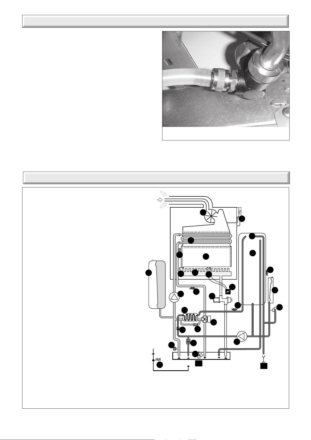
Note: To obtain a products of combustion reading, unscrew the
left hand sampling point cap on the flue elbow, located on top
of boiler.
Connect the analyser tube onto sampling point.
Switch on the electrical supply and gas supply, then operate the
boiler.
On completion of the test switch off the electrical supply and the
gas supply, remove analyser tube and replace sampling point
cap.
Car 033
Diagram 17.1
PRODUCTS
SAMPLING
POINT
17.2 Service Check and Preparation.
• Operate boiler and check for any faults that need to be put
right.
• Isolate boiler from the gas and electrical supplies.
• On completion check all gas-carrying parts for soundness with
leak detection fluid.
• Remove boiler casing as follows:
17.3 Front panel
• Unscrew and remove the two front panel retaining brackets
from the top of the boiler.
• Remove panel by lifting up and forward.
17.4 Sealed chamber cover
• Unclip the toggle clip holding the sealed chamber cover, see
diagram. 17.1.
• Lift cover up and off boiler.
17.5 Control panel
• Lift control panel up and lower forwards to gain access to lower
part of boiler.
9318
Diagram 17.2
17.6 Side panels
• Unscrew and remove the four screws securing lower grille onto
boiler. Unhook grille from rear of boiler and remove.
• Remove three screws from front of each side panel.
• Lift each panel up and then forward to remove.
(For ease of access if required)
17.7 Combustion chamber cover
• Unscrew the two screws securing combustion chamber cover
to combustion chamber, see diagram 17.2.
•Remove combustion chamber cover from boiler.
Ech 052
4000116705-2
28
Page 29

17 Routine Cleaning and Inspection
17.8 Burner, refer to diagram 17.3.
• Undo main gas supply nut from under the sealed chamber.
Note: The washer between main burner and main burner gas
supply must be kept for use on reassembly.
• Pull off ignition leads from ignition unit.
• Pull off flame sense lead from flame sense electrode.
• Unscrew and remove burner support bracket securing screw
and remove bracket.
• Remove burner from boiler by lifting up and pulling forwards
easing the leads through the grommet, taking care not to
damage insulation.
• Clean burner by washing in soapy water. Dry thoroughly
before refitting.
• When refitting burner ensure that rear of burner locates into
location slot and the injector locates correctly through the
grommet.
Note: To gain access to injectors for removal, refer to Section,
20.24 in Replacement of Parts.
GROMMET
17.9 Heat exchanger, refer to diagram 17.4.
• Disconnect electrical connections from fan.
• Unscrew and remove two fan retaining screws from the right
hand side edge of fan mounting plate.
• Remove fan with mounting plate attached by pulling forward
and out of boiler.
• Remove air pressure switch sensing tube at rear of flue hood.
• From front of boiler carefully unclip wire spring retainers from
side of flue hood.
• Remove the overheat thermostat by unclipping from the
heating return pipe.
• Lift flue hood clear of heat exchanger and examine for debris.
• Using a soft brush or vacuum clean as required.
DO NOT USE ANY TOOL LIKELY TO DAMAGE PAINTED
FINISH OF HEAT EXCHANGER.
Note: When re-fitting fan, make sure that the two lugs on the fan
mounting plate engage in the flue hood
11755
MAIN GAS
SUPPLY NUT
IGNITION
LEADS
BURNER
SUPPORT
BRACKET
FLAME
SENSE
LEAD
11756
9341
FAN
RETAINING
SLOTS
11759
11757
11758
➜
AIR PRESSURE SWITCH
SENSING TUBE
OVERHEAT
THERMOSTAT
BURNER
LOCATION
SLOT
Diagram 17.3
9345
29
WIRE SPRING
RETAINER
2 OFF
11760
Diagram 17.4
4000116705-2
Page 30

17 Routine Cleaning and Inspection
17.10 Spark and Sense Gaps
• Check that the spark and sense gaps as shown in diagram
17.5.
17.11 Domestic hot water discharge (Annual
Check)
Refer to diagram 5.1. Open expansion valve (24) and
temperature/pressure release valve (27) and check that the
discharge outlet is not blocked (D2) and that the valves close,
check the pressure reducing valve and strainer and clean if
necessary, check the air pressure in the domestic expansion
vessel (26) and recharge if required.
17.12 Reassembly of parts removed for
servicing
All parts are replaced in reverse order to removal.
17.13 Flue system
• Check externally to make sure that flue is not blocked
• Inspect flue system to make sure that all fittings are secure.
17.14 Operation of fan
• Switch on electrical supply and turn on gas.
• Light burner by opening a hot water tap.
• Check that fan operates when burner lights and stops when it
goes out.
17.15 Cold water inlet filter
Drain down domestic hot water circuit of boiler only, as follows:
• Close isolating valve/throttle (m) on cold water isolating cock,
see diagram 8.1.
Note: This valve is closed when screwed fully clockwise.
• Drain DHW boiler circuit, refer to Section 4.2.
• Undo connecting nut from boiler cold water inlet connection.
• Clean and inspect filter, replace if necessary, see diagram
17.6.
• With both filter and restrictor in place, reconnect connecting
pipe to inlet connection and tighten.
• Fully open isolating valve/throttle on cold water inlet and check
for leaks.
4mm
SPARK GAP
SENSE GAP
FLOW
RESTRICTOR
AND COLD
WATER INLET
FILTER
4mm
9326
5mm
9327
Diagram 17.5
9339
Diagram 17.6
4000116705-2
30
Page 31

18 Fault Finding
WARNING. Always isolate the boiler from the electrical supply
before carrying out any electrical replacement work.
On completion of a fault finding task that has required the
disconnection and making of electrical connections, the check
for earth continuity, polarity and resistance to earth must be
carried out.
If any gas-carrying components are disturbed, removed or
replaced it will be necessary on completion to check for gas
soundness with leak detection fluid.
Before trying to operate the boiler make sure that :
• All gas supply cocks are open and that the gas supply has
been purged of air.
Table 2
Voltage Measured value Measuring point
230 Volt 230 V AC Between terminals H8.1 and H8.2
24 Volt maximum 33V DC Between terminals B2.4 and B2.7
15 Volt 15V + 0.5V Between terminals B2.4 and B2.2
Display 5V + 0.5V Between terminals B2.4 and B4.2
• The heating system pressure is at least 1 bar.
• There is a permanent mains supply to the boiler.
• The fuse on the PCB is intact.
Preliminary electrical system checks, as outlined in a multimeter
instruction book, are the first checks to be carried out during a
fault finding procedure.
Should there be any doubt about the voltage supply to any of the
components, it is possible to carry out a simple electrical test to
ensure all is operational in that area.
To carry out the electrical test, gain access to the main Printed
Circuit Board (PCB), as described previously, and measure the
voltages according to table 2.
The XTRAMAX has an on-board fault diagnostic
system. Should a fault occur on the boiler, the warning
LED at the top of the user display will illuminate
and the LCD display will indicate the precise area
Sec 052
09 FF
where the fault has occurred.
A fault code is displayed on the left hand side of the LCD display, whilst at the same time, the letters appear with a
telephone symbol.
Thermistor values
The following table applies to the central heating, domestic hot
water and storage vessel thermistors:
Temperature (°C) Resistance (Ω)
0 32565
5 25345
10 19875
15 15700
20 12500
25 10000
30 8060
35 6535
40 5330
45 4370
50 3605
55 2989
60 2490
65 2085
70 1755
75 1480
80 1260
85 1070
90 920
95 785
100 680
System pressure sensor
The resistance of the sensor at various pressures is as follows:
0 bar between 280 Ω and 320 Ω
1 bar between 195 Ω and 220 Ω
3 bar between 93 Ω and 143 Ω
31
4000116705-2
Page 32

18 Fault Finding
TO AID FAULT FINDING REFER TO DIAGRAMS 5.1 and 19.1.
CODE CHECKDISPLAY SYMBOL
00
02
04
05
06
07
08
09
12
13
14
15
16
17
20
21
TYPE OF FAULT
NO FAULT
AIR FLOW SAFETY
NO IGNITION
Note: MAX. IGNITION TIME
= 7 SECONDS
OVERHEATING
LOOP
HEATING THERMISTOR
ON FLOW PIPE
DOMESTIC THERMISTOR
ON DHW PIPE
TEMPERATURE ON
STORAGE VESSEL
LOSS OF WATER
PRESSURE SENSOR.
USER INTERFACE
MAIN CONTROL BOARD
GAS LEAK THROUGH THE
SAFETY ELECTRIC VALVES
COMMUNICATION FAULT
LACK OF WATER IN PRIMARY
(PCB)
TEMPERATURE LIMITER.
CONTROLLED BY THE
HEATING THERMISTOR
ON FLOW PIPE.
STEP MOTOR FAILURE
NETWORK VOLTAGE
TOO LOW
CIRCUIT
NO FAULT
THIS SYMBOL IS NOT INSTANTANEOUS BUT IF IT APPEARS
AFTER 40 SECONDS, CHECK
• THE FLUE SYSTEM FOR A BLOCKAGE, EXCESS LENGTH.
• CHECK THE AIR PRESSURE SWITCH.
• CHECK THE ELECTRICAL CONNECTIONS.
IF THE BURNER LIGHTS AND GOES OUT AFTER 7 SECONDS.
• CHECK THE ELECTRODE AND ITS CORRECT CONNECTION.
• CHECK IGNITION.
• CHECK THERE IS MORE THAN 40V BETWEEN LIVE AND EARTH.
IF THE BURNER DOES NOT LIGHT, CHECK .
• THE GAS TAP ON THE INSTALLATION IS OPEN.
• THE GAS CONTROL VALVE.
• CHECK THE IGNITON.
IF NO SPARK IS PRESENT THEN
• CHECK THE IGNITER AND CONNECTIONS
• PUMP BLOCKED OR ITS CONDENSER OUT OF SERVICE.
• ISOLATING COCKS CLOSED ON JIG.
• DEFECTIVE OVERHEAT THERMOSTAT.
• BLEED OUT AIR.
• CHECK THE ELECTRICAL CONNECTIONS.
• CIRCUITS OPEN OR SHORT CIRCUIT.
• CHECK RESISTANCE OF THE THERMISTOR. (12500 ohms AT
20°C. 1750 ohms AT 70°C).
• UNCLIP THE THERMISTOR FROM THE PIPE, IF THE BOILER
RE-LIGHTS WHEN THE THERMISTOR IS OPEN CIRCUIT.
REPLACE THE THERMISTOR.
• SENSOR IN SHORT CIRCUIT OR HAS ISOLATION FAULT.
• CHECK THE ELECTRICAL CONNECTIONS.
• INTERFACE MAY BE DAMP. DRY IT OUT OR REPLACE.
THIS FAULT MAY BE INTERMITTENT.
• SWITCH (OFF), WAIT APPROXIMATLEY 5 SECONDS, SWITCH (ON).
• IF FAULT PERSISTS. REPLACE MAIN CONTROL BOARD (PCB).
• CHECK HEATING THERMISTOR (MAY BE UNCLIPPED) OR
THREE WAY VALVE FAULTY.
• FAULTY PUMP.
• LOW HEATING FLOW RATE.
• MOTOR CONNECTION OR MOTOR FAILURE.
• CHECK THE SAFETY ELECTRIC VALVE
• CHECK THE SAFETY ELECTRIC VALVE
THIS FAULT MAY BE OCCASIONAL AND CAUSED BY
ELECTROMAGNETIC INTERFERENCE, OTHERWISE
• CHECK THE MAIN CONTROL BOARD (PCB).
• PERFORM WATER TOPPING - UP
4000116705-2
OTHER FAULTS NOT DISPLAYED BY FAULT CODE
NO HEATING
NO HEATING.
NO DISPLAY OF
RADIATOR SYMBOL.
WATER NOT HOT ENOUGH,
OR UNEVEN FLOW FROM
TAP. THERE IS A
HOT WATER DEMAND.
WATER NOT HOT ENOUGH,
OR UNEVEN FLOW FROM
TAP. NO DISPLAY OF
TAP SYMBOL.
THE BURNER COMES ON
WHEN COLD WATER
IS DRAWN OFF.
THERE IS DEMAND BY THE ROOM TEMPERATURE THERMOSTAT.
• CHECK THE CONNECTIONS.
IF FAULT PERSISTS, REPLACE MAIN CONTROL BOARD (PCB).
• CHECK THAT CONTACT 1 IS ON 1. OR MEASURE A RESISTANCE
< 10 ohms BETWEEN B5.1 AND B5.2.
• CHECK ROOM THERMOSTAT CONNECTIONS OR MEASURE A
RESISTANCE < 50 ohms BETWEEN B3.1 AND B3.2.
• CHECK THREE WAY VALVE.
• CHECK THREE WAY VALVE MOTOR (SWITCHING).
• CHECK THE DIRECTION OF CLIP
ON THREE WAY VALVE (READABILITY OF SYMBOL).
• MEASURE THE MICROFAST RESISTANCE = 1000 ohms
BETWEEN H4.1 AND H4.3.
• READ THE VALUE OF FLOW RATE DETECTOR ON CODE 07 OF
INFO MENU. IT WILL READ HOT WATER OUTPUT (L/MIN.)(x10)
VALID RANGE 00,,,199 NOTE: DIVIDE THE VALUE BY 10.
IF = 0 THE DETECTOR IS BLOCKED OR THE
MAIN CONTROL BOARD (PCB) HAS FAILED.
• CHECK THAT THE HOT WATER CIRCUIT HAS BEEN BLED
PROPERLY (ANY AIR BUFFER MAY ACTIVATE THE FLOW RATE
DETECTOR WHEN THE TAPS ARE TURNED ON).
R
O
K
32
9526
Page 33

19 Wiring Diagram
FAN
g
p
w
FAN
SENSOR
WATER
PRESSURE
SENSOR
g
or
w
OVERHEAT
THERMISTOR
bk
bk
THERMISTOR
w
w
CH
w
g
PLUG
THERMISTOR
DHW
rr
ww
FLOW SENSOR
br
AIR PRESSURE
SWITCH
3
1
bk
bk
STORAGE VESSEL
THERMISTOR
230V~50Hz
PERMANENT
MAINS SUPPLY
FUSED AT 3A
IGNITION
ELECTRODES
bg/y
CONTROL
wg
p
CHASSIS
EARTH
SENSE
ELECTRODE
GAS
VALV E
THREE-WAY
PUMP CH
bk
VALV E
IGNITION
MODULE
CHASSIS
EARTH
PUMP DHW
ON/OFF
SWITCH
bk
2
4
1
3
USER INTERFACE
bk
bk
H2
H8
H5
NOTE 'E'
J2
J19
J4
br
J3
b
g/y
J16
NOTE 'F'
g/y g/yg/y g/y
J6
S2
H4
J5
J9
J8
SW3
S1
H1
H3
H6
FUSE
125mAT
NOTE 'E' VOLTA GE FREE room thermostat connection or link.
NOTE 'F' Optional remote control unit with
programmable room stat connection Part No. 86774
b
br
bk bk
br
b
bk
br
b
g/y
g/y
b
br
br
g/y
b
KEY
bk- BLACK
w- WHITE
or- ORANGE
g/y- GREEN/
YELLOW
br - BROWN
b- BLUE
p- PINK
g- GREY
r- RED
Diagram 19.1
11750
33
4000116705-2
Page 34

20 Replacement of Parts
To drain the domestic hot water circuit (DHW) of the boiler
Close isolating valve/throttle (m)
Note: This valve is closed when screwed fully clockwise.
Open the DHW drain point (z) located below the DHW pump.
To drain the central heating circuit (CH) of the boiler
Close isolating valves (q) and (v)
Note: These valves are closed when slots are at right angles to direction of flow.
Open drain valves (r) and (u)
9527
➜
z
u
➜
v
IMPORTANT INFORMATION
Replacement of parts must be carried out by a competent
person.
WARNING: Before commencing the replacement of any
component, isolate appliance from electrical supply and turn off
gas at service cock.
When replacing components it may be necessary to renew
sealing washers, gaskets and 'O' rings. If new ones are supplied
with replacement components they must be used.
Unless stated otherwise parts are replaced in reverse order to
removal.
If any gas carrying components are disturbed, removed or
replaced, it will be necessary on completion to check for gas
soundness with leak detection fluid and if necessary carry out
functional test of the controls.
20.1 Domestic hot water thermistor
Before starting refer to the front of Section 20 Important
information.
• Remove the front panel, refer to Section 17.3.
• Lower the control panel, refer to Section 17.5.
• Locate domestic hot water thermistor on hot water flow pipe on
right hand side of boiler adjacent to gas valve, see diagram
20.2.
• Unclip thermistor from pipe.
• Disconnect leads from thermistor.
• Fit leads to replacement thermistor and fit thermistor to pipe.
The polarity is not important.
20.2 Central heating thermistor
Before starting refer to the front of Section 20 Important
information.
• Remove the front panel, refer to Section 17.3.
• Lower the control panel, refer to Section 17.5.
• Locate central heating thermistor on heating flow pipe on
centre of boiler, see diagram 20.3.
➜
m
r
9126
➜
q
Diagram 20.1
9331
DOMESTIC HOT
WATER
THERMISTOR
Diagram 20.2
11761
CENTRAL
HEATING
THERMISTOR
Diagram 20.3
• Unclip thermistor from pipe.
• Disconnect leads from thermistor.
• Fit leads to replacement thermistor and fit thermistor to pipe.
The polarity is not important.
4000116705-2
34
Page 35

20 Replacement of Parts
20.3 Domestic hot water storage vessel
thermistor
Before starting refer to the front of Section 20 Important
information.
• Remove the front panel, refer to Section 17.3.
• Lower the control panel, refer to Section 17.5.
• Unscrew and remove two screws securing right hand side
panel to boiler.
• Swing out side panel to gain access to thermistor on right hand
side of cylinder.
• Disconnect plug connection to thermistor lead.
• Remove plug of insulation from right hand side of cylinder, see
diagram 20.4.
• Peel off the self adhesive thermistor, see diagram 20.4.
• Fit replacement thermistor.
20.4 Fan, refer to diagram 17.4
Before starting refer to the front of Section 20 Important
information.
• Remove the front panel, refer to Section 17.3.
• Remove the sealed chamber cover, refer to Section 17.4.
• Disconnect electrical connections from fan.
• Unscrew and remove two fan retaining screws at front edge of
mounting plate.
• Remove fan with mounting plate attached by pulling forwards
out of the boiler.
• Remove fan from mounting plate.
• Fit replacement fan.
Note: When re-fitting, make sure that the two lugs on the fan
mounting plate engage in the flue hood.
• Reconnect electrical leads.
INSULATION
PLUG
SELF ADHESIVE
THERMISTOR
9347
9346
Diagram 20.4
11762
20.5 Air pressure switch
Before starting refer to the front of Section 20 Important
information.
• Remove the front panel, refer to Section 17.3.
• Locate air pressure switch situated outside combustion chamber
on top right hand side, see diagram 20.5.
• Remove air pressure switch tubes from sensing probe on flue
hood and combustion chamber.
• Disconnect air pressure switch electrical connections.
• Undo screws on top of boiler securing air pressure switch to
boiler and remove switch.
• Transfer mounting bracket from old air pressure switch to new
air pressure switch.
• Fit replacement switch, ensuring that pressure sensing tubes
are fitted to correct connections on switch.
Diagram 20.5
35
4000116705-2
Page 36

20 Replacement of Parts
20.6 Domestic water flow sensor
Before starting refer to the front of Section 20 Important
information.
• Remove the front panel, refer to Section 17.3.
• Lower the control panel, refer to Section 17.5.
• Drain down domestic hot water circuit of boiler only, see
diagram 20.1.
• Locate flow sensor on cold water inlet pipe to boiler inside
controls area, see diagram 20.6.
• Carefully pull off electrical connector from flow sensor.
• Pull out slotted metal clip securing cold water inlet pipe to flow
sensor and carefully remove from sensor.
• Pull out slotted metal clip securing flow sensor to pump
mounting and carefully remove sensor from boiler.
• Fit replacement sensor.
20.7 Printed circuit board (PCB)
Before starting refer to the front of Section 20 Important
information.
• Remove the front panel, refer to Section 17.3.
• Lower the control panel, refer to Section 17.5.
• Gain access to rear of control panel.
• Unclip side clips and hinge up control panel cover to gain
access to PCB, see diagram 13.2.
• Carefully pull off electrical connections to PCB.
• Unclip and lift out PCB.
• Fit replacement PCB, ensure that PCB connections are fully
pushed onto replacement PCB. Set the heating temperature
option to the same value as the old PCB, refer to relevant part
of Section 13 and diagram 13.3.
• Fit replacement pump.
• Open isolating valves on flow and return connections, refill,
and pressurise boiler.
• Check for leaks.
20.9 Hot water plate to plate heat exchanger
Before starting refer to the front of Section 20 Important
information.
• Remove the front panel, refer to Section 17.3.
• Lower the control panel, refer to Section 17.5.
• Drain down central heating and domestic hot water circuits of
boiler only, see diagram 20.1.
• Supporting domestic heat exchanger, unscrew and remove
two screws securing it onto pump mounting and 3-way valve/
bypass housing.
• Remove plate to plate heat exchanger from boiler.
• Fit replacement plate to plate heat exchanger.
Note: Plate to plate heat exchanger mounting screws are offset
to ensure correct fitting of replacement.
11763
20.8 Central heating pump, refer to diagram
20.7.
Before starting refer to the front of Section 20 Important
information.
• Remove the front panel, refer to Section 17.3.
• Lower the control panel, refer to Section 17.5.
• For ease of access if required remove the left hand side panel,
refer to Section 17.6.
• Drain down central heating water circuit of the boiler only, see
diagram 20.1.
• Undo two fixing screws and remove pump retaining bracket
from front of pump.
• Undo two jubilee clips securing pump outlet hose connection
to pump.
• Slide clips upwards to give access to hose.
• Slide hose along pipe to clear pump outlet.
• Remove pump from pump block by lifting up at front and pulling
forward.
• Gain access to the pump electrical connection box and remove
cover.
• Disconnect pump cable from pump (avoid straining cables).
• Transfer automatic air vent to replacement pump.
• Re-connect electrical connection.
Diagram 20.6
11764
Diagram 20.7
4000116705-2
36
Page 37

20 Replacement of Parts
20.10 Three-way valve head
Before starting refer to the front of Section 20 Important
information.
• Remove the front panel, refer to Section 17.3.
• Lower the control panel, refer to Section 17.5.
• Locate 3- way valve in centre of lower controls area.
• Remove electrical plug from valve head.
• Pull out slotted metal clip from valve body and remove valve
head from body.
• Fit replacement valve head.
Note :
1) When refitting clip, ensure that letters OK are as shown, see
diagram 20.8.
2) It is not necessary to drain boiler to carry out this work.
20.11 Three-way valve/bypass housing
Before starting refer to the front of Section 20 Important
information.
• Remove the front panel, refer to Section 17.3.
• Lower the control panel, refer to Section 17.5.
• Drain down central heating and domestic hot water circuit of
boiler only, see diagram 20.1.
Note: It is not necessary to drain down entire heating system to
carry out this work.
• Remove 3-way valve head, refer to Section 20.10.
• Remove domestic hot water plate to plate heat exchanger,
refer to Section 20.9.
• Undo pipe connection from 3-way valve/bypass housing to
primary heat exchanger, see diagram 20.9.
• Pull out slotted metal clips and remove bypass pipe.
• Pull out slotted metal clip and remove domestic pipe from 3way valve/bypass housing to storage vessel.
• Remove central heating flow pipe from 3-way valve/bypass
housing to fixing jig.
• From underneath boiler, undo two screws securing 3-way
valve/bypass housing and lift out of boiler.
• Fit replacement 3-way valve/bypass housing.
20.13 System water pressure sensor
Before starting refer to the front of Section 20 Important
information.
• Remove the front panel, refer to Section 17.3.
• Lower the control panel, refer to Section 17.5.
• Drain down central heating water circuit of the boiler only, see
diagram 20.1.
• Locate system pressure sensor at front left hand side of boiler,
see diagram 20.10.
• Remove electrical connections from sensor.
• Pull off slotted metal clip and remove sensor from boiler.
• Fit replacement sensor.
➜
Pho483
Diagram 20.8
PIPE CONNECTION
9349
20.12 Bypass
Before starting refer to the front of Section 20 Important
information.
• Remove the front panel, refer to Section 17.3.
• Lower the control panel, refer to Section 17.5.
• Drain down central heating water circuit of the boiler only, see
diagram 20.1.
Note: it is not necessary to drain down the entire heating system
to carry out this work.
• Pull out slotted metal clips and remove bypass pipe.
• Pull out slotted metal clip securing bypass into bypass housing,
remove bypass.
• Fit replacement bypass.
37
Diagram 20.9
11765
Diagram 20.10
4000116705-2
Page 38

20 Replacement of Parts
20.14 Gas control valve stepper motor, refer to
diagram 20.11.
Before starting refer to the front of Section 20 Important
information.
• Remove the front panel, refer to Section 17.3.
• Lower the control panel, refer to Section 17.5.
• Locate gas valve stepper motor attached to front of gas valve.
• Disconnect multi-plug from stepper motor.
• Remove screws securing stepper motor onto gas valve body.
• Withdraw stepper motor from gas valve body.
• Fit replacement stepper motor taking care not to damage the
'O' ring.
20.15 Gas Control valve assembly, refer to
diagram 20.11.
Before starting refer to the front of Section 20 Important
information.
• Remove the front panel, refer to Section 17.3.
• Lower the control panel, refer to Section 17.5.
• Disconnect multi-plug from stepper motor.
• Disconnect electrical connections from spark ignition unit
above gas valve assembly.
• Disconnect electrical connection from R/H side of gas control
valve assembly mounting bracket.
• Undo main gas supply nut from main burner, see diagram
17.3.
Note: The washer must be kept for use on reassembly.
• Undo main gas union nut between gas control valve supply
pipe and gas inlet valve.
Note: The washer must be kept for use on reassembly.
• Unscrew and remove screws securing gas control valve
mounting bracket to boiler frame.
• Withdraw gas control valve assembly, pipes and bracket,
taking care not to strain the electrical connection at the rear of
the gas control valve.
• While supporting the gas control valve assembly disconnect
the electrical connection at the rear of the gas control valve, see
diagram 20.11.
• Using the old gas control valve as a guide, transfer gas pipes
and bracket from old gas control valve to replacement gas
control valve.
• Fit replacement gas control valve assembly into boiler.
SPARK IGNITION UNIT
➜
GAS CONTROL
VALVE STEPPER
MOTOR
11767
REAR OF GAS
CONTROL VALVE
ASSEMBLY
➜
➜
➜
➜
➜
Diagram 20.11
11766
➜
4000116705-2
38
Page 39

20 Replacement of Parts
20.16 Gas safety valve, refer to diagram 20.11.
Before starting refer to the front of Section 20 Important
information.
• Remove the front panel, refer to Section 17.3.
• Lower the control panel, refer to Section 17.5.
• Remove the gas control valve assembly, refer to Section
20.15.
• Locate gas safety valve on the rear of the gas control valve.
• Unscrew and remove the 2 screws securing the gas safety
valve to the gas control valve.
• Fit replacement gas safety valve taking care not to damage the
'O' ring.
• Refit gas control valve assembly into boiler.
20.17 Spark ignition unit, refer to diagram
20.11.
Before starting refer to the front of Section 20 Important
information.
• Remove the front panel, refer to Section 17.3.
• Lower the control panel, refer to Section 17.5.
• Disconnect electrical connections from spark ignition unit.
• Remove screw securing spark ignition unit to gas control valve
mounting bracket.
• Fit replacement spark ignition unit.
20.18 Central heating safety valve
Before starting refer to the front of Section 20 Important
information.
• Remove the front panel, refer to Section 17.3.
• Lower the control panel, refer to Section 17.5.
If safety valve seating is damaged, it will be necessary to
replace safety valve as a complete unit, repair is not possible.
Drain down central heating water circuit of the boiler only, see
diagram 20.1.
• Disconnect safety valve discharge pipe from safety valve.
• Remove wire clip securing safety valve to fixing jig and remove
safety valve, see diagram 20.12.
• Fit replacement safety valve.
Note: Apply a small quantity of silicon grease to the safety valve
'O' ring prior to fitting.
20.19 Main heat exchanger
Before starting refer to the front of Section 20 Important
information.
• Remove the front panel, refer to Section 17.3.
• Remove the sealed chamber cover, refer to Section 17.4.
• Lower the control panel, refer to Section 17.5.
• Remove the combustion chamber cover, refer to Section
17.7.
• Drain down central heating water circuit of the boiler, see
diagram 20.1.
• Release flue hood as follows:
From front of boiler carefully unclip wire spring retainers from
side of flue hood.
• Undo nut securing pipe from heat exchanger to 3-way valve/
bypass housing.
• Whilst supporting heat exchanger, undo nut securing pipe
from heat exchanger to central heating pump.
• Slide heat exchanger forwards and remove from boiler taking
care not to damage insulation.
DO NOT DAMAGE PAINTED FINISH OF HEAT EXCHANGER
• Fit replacement heat exchanger.
Note: Locate heat exchanger into slot at rear of combustion
chamber.
20.20 Central heating expansion vessel
Before starting refer to the front of Section 20 Important
information.
• Remove the front panel, refer to Section 17.3.
• Lower the control panel, refer to Section 17.5.
Drain down central heating water circuit of the boiler, see
diagram 20.1.
Undo pipe coupling on expansion vessel.
Unscrew and remove expansion vessel retaining nut.
Supporting expansion vessel, unscrew and remove screws
securing expansion vessel bracket to boiler.
Lift expansion vessel out of boiler.
Fit replacement expansion vessel.
Note: Check that expansion vessel pressure is correct, see
‘Section 1 Technical Data’.
9126
➜
39
Diagram 20.12
4000116705-2
Page 40

20 Replacement of Parts
20.21 Overheat thermostat
Before starting refer to the front of Section 20 Important
information.
• Remove the front panel, refer to Section 17.3.
• Remove sealed chamber cover, refer to Section 17.4.
• Locate high limit thermostat on heating flow pipe on left hand
side of boiler, see part of diagram 17.4.
• Disconnect electrical connection from thermostat
• Unclip thermostat from heating flow pipe.
• Fit replacement thermostat in reverse order to removal. (Use
heat sink compound supplied).
• Refit connection to thermostat.
20.22 Combustion chamber insulation
Before starting refer to the front of Section 20 Important
information.
• Remove the front panel, refer to Section 17.3.
• Remove sealed chamber cover, refer to Section 17.4.
• Remove combustion chamber cover, refer to Section 17.7.
• Remove main heat exchanger, refer to Section 20.19.
• Remove fan and loosen flue hood, refer to relevant parts of
Section 17.9.
SIDE
➜
SECURING RODS
9524
➜
➜
Front panel insulation
• Bend back small retaining lugs, remove the front insulation
panel free from retaining lugs on combustion chamber cover.
Rear panel insulation
• Pull rear insulation panel free from retaining lug at rear of
combustion chamber by tilting forward.
Side Panels
Note: Rear panel must be removed first.
• Pull out side panels free from retaining lugs at side of
combustion chamber by tilting sideways.
20.23 Burner
Before starting refer to the front of Section 20 Important
information.
• Remove the front panel, refer to Section 17.3.
• Remove sealed chamber cover, refer to Section 17.4.
• Lower the control panel, refer to Section 17.5.
• Remove combustion chamber cover, refer to Section 17.7.
• Remove burner, refer to Section 17.8.
Assemble replacement burner, supplied in parts, as follows:
• Fit burner injectors to burner injector bar and tighten.
Note: Make sure that injector size, marked on each injector, is
the same as that given in ‘Section 1 Technical Data’ for the
type of gas being used.
• Fit injector bar into burner, secure with retaining rods.
• Fit replacement burner.
Note: To aid in assembling the burner, refer to Section 20.24.
INJECTOR
➜
➜
BLADE
SECURING
BAR
➜
9523
9350
4000116705-2
Diagram 20.13
40
Page 41

20 Replacement of Parts
20.24 Burner injectors, refer to diagram 20.13.
Before starting refer to the front of Section 20 Important
information.
• Remove the front panel, refer to Section 17.3.
• Remove sealed chamber cover, refer to Section 17.4.
• Lower the control panel, refer to Section 17.5.
• Remove combustion chamber cover, refer to Section 17.7.
• Remove burner, refer to Section 17.8.
• Remove the ignition spark assembly.
• Position the burner on a flat surface and remove side pieces
by removing the screws and unhooking the sides.
• Remove the two securing rods.
• Remove the appropriate securing bar and burner blade to
access the injector
Note: Make sure that injector size, marked on each injector, is
the same as that given in ‘Section 1 Technical Data’ for the
type of gas being used.
• Assemble the burner taking care to engage all parts correctly.
• Refit burner into boiler.
20.25 Ignition electrode
Before starting refer to the front of Section 20 Important
information.
• Remove the front panel, refer to Section 17.3.
• Remove sealed chamber cover, refer to Section 17.4.
• Lower the control panel, refer to Section 17.5.
• Remove combustion chamber cover, refer to Section 17.7.
• Remove burner, refer to Section 17.8.
• Undo and remove screw securing electrode onto burner.
• Fit replacement electrode.
• Refit burner into boiler.
• Unclip side clips and hinge up control panel cover, see
diagram 13.2.
• Carefully pull off electrical connection from the user interface
board to PCB at (J16).
• Remove the two securing screws to release the control panel
fascia.
• Remove the two user interface board assembly securing
screws to remove the user interface board assembly.
• Fit replacement user interface board assembly.
20.28 Mains power switch, refer to diagram
20.14.
Before starting refer to the front of Section 20 Important
information.
• Remove the front panel, refer to Section 17.3.
• Lower the control panel, refer to Section 17.5.
• Gain access to rear of control panel.
• Unclip side clips and hinge up control panel cover, see
diagram 13.2.
• Remove the mains power switch.
• Carefully pull off electrical connections from the mains power
switch.
• Fit replacement mains power switch.
CONTROL PANEL FASCIA
SECURING SCREWS
11768
20.26 Flame sense electrode
Before starting refer to the front of Section 20 Important
information.
• Remove the front panel, refer to Section 17.3.
• Remove sealed chamber cover, refer to Section 17.4.
• Lower the control panel, refer to Section 17.5.
• Remove combustion chamber cover, refer to Section 17.7.
• Remove burner, refer to Section 17.8.
• Undo and remove screw securing electrode onto burner.
• Fit replacement electrode.
• Refit burner into boiler.
20.27 User interface board assembly, refer to
diagram 20.14.
Before starting refer to the front of Section 20 Important
information.
• Remove the front panel, refer to Section 17.3.
• Lower the control panel, refer to Section 17.5.
• Gain access to rear of control panel.
USER
INTERFACE
BOARD
ASSEMBLY
SECURING SCREWS
J16
ELECTRICAL
CONNECTION
MAINS
POWER
SWITCH
9528
Diagram 20.14
41
4000116705-2
Page 42

20 Replacement of Parts
20.29 Domestic hot water pump, refer to
diagram 20.15.
Before starting refer to the front of Section 20 Important
information.
• Remove the front panel, refer to Section 17.3.
• Lower the control panel, refer to Section 17.5.
• Drain down domestic hot water circuit of boiler only, see
diagram 20.1.
• Remove pump head from pump block by unscrewing and
removing the four hex-head retaining screws, remove and
support pump head to avoid straining electrical cable.
• Remove cover from the electrical connection box.
• Disconnect pump cable from pump.
• Fit replacement pump head.
20.30 Domestic Hot water expansion vessel,
refer to diagram 20.16.
Before starting refer to the front of Section 20 Important
information.
• Remove the front panel, refer to Section 17.3.
• Lower the control panel, refer to Section 17.5.
• Remove R.H. side panel, refer to Section 17.6.
• Drain down domestic hot water circuit of boiler only, see
diagram 20.1.
• Undo pipe coupling on domestic hot water expansion vessel.
• Unscrew and remove domestic hot water expansion vessel
retaining nut.
• Remove domestic hot water expansion vessel.
• Fit replacement domestic hot water expansion vessel.
20.31 Temperature pressure relief valve, refer
to diagram 20.17.
Before starting refer to the front of Section 20 Important
information.
• Remove the front panel, refer to Section 17.3.
• Drain down domestic hot water circuit of boiler only, see
diagram 20.1.
• Undo couplings to remove temperature pressure relief valve.
• Fit replacement temperature pressure relief valve.
ELECTRICAL
CONNECTION BOX
➜➜
9649
11769
➜➜
HEX-HEAD
RETAINING
SCREWS
(4OFF)
PUMP HEAD
Diagram 20.15
DOMESTIC HOT WATER
EXPANSION VESSEL
RETAINING
NUT
PIPE
COUPLING
9657
Diagram 20.16
20.32 Domestic Hot water expansion valve,
refer to diagram 20.18.
Before starting refer to the front of Section 20 Important
information.
• Remove the front panel, refer to Section 17.3.
• Lower the control panel, refer to Section 17.5.
• Drain down domestic hot water circuit of boiler only, see
diagram 20.1.
• Undo couplings to remove domestic hot water expansion
valve.
• Fit replacement domestic hot water expansion valve.
4000116705-2
TEMPERATURE PRESSURE
RELIEF VALVE
42
➜
11770
➜
Diagram 20.17
Page 43

20 Replacement of Parts
DOMESTIC HOT WATER
EXPANSION VALVE
9650
➜
➜
Diagram 20.18
20.33 Domestic Hot water storage vessel, refer
to diagram 20.19.
Before starting refer to the front of Section 20 Important
information.
• Remove the front panel, refer to Section 17.3.
• Lower the control panel, refer to Section 17.5.
• Remove R.H. side panel, refer to Section 17 6.
• Drain down central heating and domestic hot water circuits of
boiler only, see diagram 20.1.
• Remove central heating expansion vessel, refer to Section
20.20.
• Remove domestic hot water expansion vessel, refer to
Section 20.30.
• Remove air pressure switch, refer to Section 20.5.
• Undo and remove the two screws securing the top side panels
support bar, remove the bar.
• Disconnect the inline electrical plug connection to the domestic
hot water storage vessel thermistor. ( The thermistor is located
on the right-hand side of the domestic hot water storage
vessel ).
• Remove top and bottom union nuts to remove the domestic hot
water pump (avoid straining electrical cable), see diagram
20.15. (The pump is removed to take the weight off the
pipework).
• Undo couplings to remove temperature pressure relief valve,
see diagram 20.17.
• Undo union nut at 'T' piece to remove temperature pressure
relief valve over flow pipe.
• Undo the three couplings at the bottom of the domestic hot
water storage vessel.
• Remove the two retaining screws from the bottom domestic
hot water storage vessel bracket, see diagram 20.19.
• Lift vessel up and forward to remove.
• Fit replacement domestic hot water storage vessel.
• Fit replacement domestic hot water storage vessel thermistor,
refer to relevant parts of Section 20.3.
9656
TOP SIDE
PANELS
SUPPORT
BAR
DOMESTIC HOT WATER
STORAGE VESSEL
UNION NUT
9652
'T' PIECE
9653
➜
➜
➜
DOMESTIC HOT WATER STORAGE
VESSEL BRACKET
9654
Diagram 20.19
43
4000116705-2
Page 44

21 Spare Parts
When ordering spare parts, quote the part number and description, stating the appliance model number and serial number from the
data badge.
Short parts list
No. ...... Description .................................................... Part No. .......................................... G.C. No.
1 .......... Domestic hot water thermistor .................... 57213 ............................................... E37381
2 .......... Central heating thermistor ......... .................. 57215 ............................................... E37382
3 .......... Storage vessel thermistor .......... ................... 57250 ............................................... E37302
4 .......... Fan .................................................................. 57238 ............................................... E37371
5 .......... Air pressure switch ......................................... 57237 ............................................... E37237
6 .......... Domestic water flow sensor ......................... 57202 ............................................... E37368
7 .......... Printed circuit board ..................................... 57248 ............................................... E37374
8 .......... Pump .............................................................. 57207 ............................................... E37411
9 .......... 3-way valve head ......................................... 57206 ............................................... E37413
10 ........ System pressure sensor ................................. 57205 ............................................... E37360
11 ........ Spark ignition unit .......................................... ...............................................
12 ........ Central heating safety valve ....................... 57228 ............................................... E37391
13 ........ Temperature/pressure relief valve .............. 56159 ...............................................
14 ........ Overheat thermostat .................................... 57212 ............................................... E37252
15 ........ Ignition electrode .......................................... 57358 ............................................... E37271
16 ........ Flame sense electrode ................................. 57195 ............................................... E37274
Notes
Because of our constant endeavour for improvement details may vary slightly from those in the instructions.
4000116705-2
44
 Loading...