

Glow Brand C140, C95 Installation & Operation Manual
Installation & Operation Manual
Models
C95 & C140
Condensing Combination Boiler
To Installer: Afx this manual adjacent to the appliance.
To Consumer: Retain these instructions for future reference
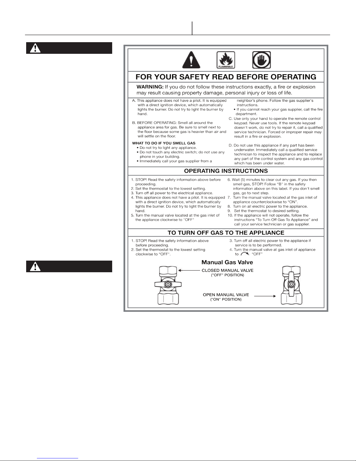
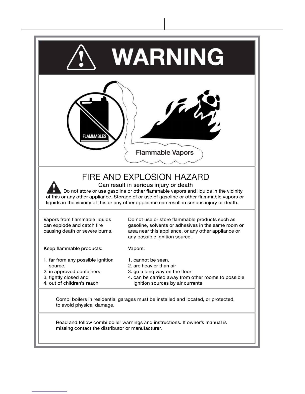
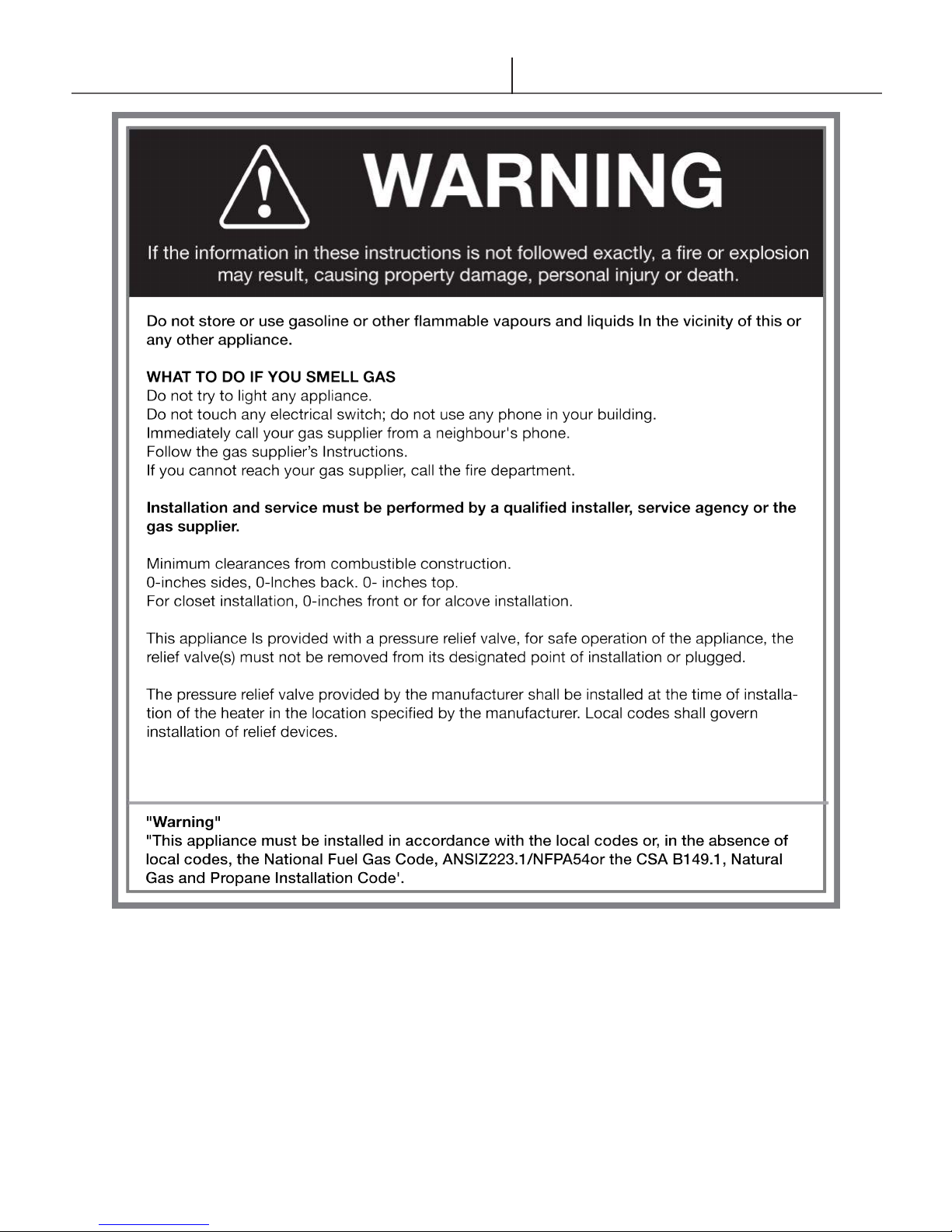
WARNING If the information in these instructions is not followed exactly, a re or explosion
may result, causing property damage, personal injury or death.
Do not store or use gasoline or other ammable vapors and liquids in the vicinity of this or any other
appliance.
WHAT TO DO IF YOU SMELL GAS
• Do not try to light any appliance.
• Do not touch any electrical switch.
• Do not use any phone in your building.
• Immediately call your gas supplier from a neighbour’s phone.
• Follow the gas supplier’s instructions.
• If you cannot reach your gas supplier, call the re department.
Installation and service must be performed by a qualied installer, service agency or
the gas supplier.
ANSI Z21.13-2017 CSA 4.9-2017
V.20180807

Glow Brand C95 & C140
Table of Contents
HAZARD SYMBOLS & DEFINITIONS 3
1. General Information
1.1 Prior to Installation 3
1.2 General information 9
2. Technical Characteristics
2.1 Technical Data 11
2.2 Unit Dimensions 12
2.3 Unit Performance 13
3. Storage, Handling & Installation
3.1 Storage 16
3.2 Unpacking 16
3.3 Boiler Location 17
3.4 Wall Mounting Installations 17
4. Venting
4.1 General Venting 18
4.2 Removing an Existing Boiler from Common
Venting System 18
4.4 Venting Guidelines 19
4.5 Direct Vent Installation 20
4.4 Venting Diagrams 24
5. Condensate Drain
5.1 Condensate Drain 30
6. Boiler and Heating System Piping
6.1 Boiler System Preparation 31
6.2 Piping Material 31
6.3 Boiler Water 31
6.5 Plumbing Schematics 35
7. Combi Boiler Operation
7.1 Combi DHW Plumbing & Set-up 39
7.2 Pre-Heat Modes 41
7.3 Glow Combi Boiler w/DHW Storage Tank 41
8. Gas Piping
8.1 Installation 42
8.2 Gas Valve and Burner Setup 42
9. Field Wiring
9.1 Line Voltage Connections 45
9.2 Low Voltage Connections 45
10. Starting Up the Boiler
10.1 Filling the unit 48
10.2 Start-Up & Ignition Safety Shuttoff Test 48
11. Controls
11.1 LCD Display & Button Layout 51
11.2 Initial Power-up 52
11.3 Main Menu 52
11.4 User Settings Menu (0.000) 53
11.5 Information Menu (1.000) 53
11.6 Installer Menu (2.000) 56
11.7 DHW Modes 59
11.8 CH Modes 60
11.9 Special Operations 61
12. Lockout, Blocking Errors & Warnings
12.1 Lockout Error 62
12.2 Blocking Errors 65
12.3 Warnings 67
12.3 Sensor Resistance 67
13. Troubleshooting
13.1 Servicing the Boiler 68
13.2 Diagnosing an Inoperative Boiler 68
14. Maintenance
14.1 General Maintenance & Inspection 71
14.2 Annual Maintenance & Inspection 71
14.3 Condensate Cleaning Instructions 72
14.4 Cleaning Primary Heat Exchanger 74
14.5 Replacing the Gas Valve 75
14.6 Replacing the Fan 76
14.7 Flow Restrictor Maintenance 77
14.8 Plate Heat Exchanger Maintenance 78
15. Part List
15.1 Part List & Diagrams 80
Warranty
Homeowner Registration Form
Warranty Part Form
Commissioning Sheet
Glow Brand C95 & C140
General Information
DANGER
Read and understand this
entire document prior to
proceeding with the
installation of the Glow Combi
Boiler. Failure to follow the
instructions outlined in this
document will result in
property damage, serious
injury or death.
WARNING
This Combi Boiler must be
installed by a licensed,
certied and trained heating
technician or the Warranty is
Void. Failure to properly
install this unit may result in
property damage, serious
injury to occupants, or
possibly death.
HAZARD SYMBOLS & DEFINITIONS
The following safety symbols are used in this manual.
DANGER
Indicates an imminently hazardous situation, which, if not avoided, will
result in severe injury or death.
WARNING
Indicates a potentially hazardous situation, which, if not avoided,
could result in severe injury or death.
CAUTION
Indicates a potentially hazardous situation, that, if not avoided, could
result in minor or moderate injury.
NOTICE
Indicates a potentially hazardous situation, that, if not avoided, could
result in property damage.
1. General Information
1.1 Prior to Installation
1. Safe, reliable operation of this boiler depends upon installation by a
professional heating contractor in strict accordance with this manual and the
requirements of the authority having jurisdiction.
• In the absence of an authority having jurisdiction, installation must be
in accordance with this manual and the National Fuel Gas Code, ANSI
Z223.1. In Canada, installation must be in accordance with the B149.1
Installation Code.
• Where required by the authority having jurisdiction, this installation
must conform to the Standard for Controls and Safety Devices for
Automatically Fired Boilers (ANSI/ASME CSD-1).
2. Read Section 4 “Venting” to verify that the maximum combustion air and
exhaust pipe lengths will not be exceeded in the planned installation.
3. Make sure that the boiler is correctly sized:
• For heating systems employing convection radiation (baseboard or
radiators), use an industry accepted sizing method such as the I=B=R
Guide RHH published by the Air-Conditioning, Heating and Refrigeration
Institute (AHRI).
• For new radiant heating systems, refer to the radiant tubing manufacturer’s
boiler sizing guidelines.
• For system which includes an indirect water heater, make sure the boiler
has the output called for by the indirect water heater manufacturer’s
instructions.
4. All Glow Combi Boilers are shipped from the factory congured for 0 - 4,500
ft. altitude. Use sea level input rate for 0 - 2,000 ft. For high altitude installation
above 4,500 ft., contact Glow Brand Manufacturing.
5. All Glow Combi Boilers are shipped from the factory congured for use with
Natural Gas only. They may NOT be converted for use with LP gas.
3
Glow Brand C95 & C140
WARNING
Crystalline SilicaCertain components conned
in the combustion chamber
may contain this potential
carcinogen. Improper
installation, adjustment,
alteration, service or
maintenance can cause
property damage, serious
injury (exposure to hazardous
materials) or death. Refer to
Section 14 for information
on handling instructions
and recommended personal
protective equipment.
Installation and service must
be performed by a qualied
installer (who must read
and follow the supplied
instructions before installing,
servicing, or removing this
boiler. This boiler contains
materials that have been
identied as carcinogenic,
or possibly carcinogenic, to
humans).
Installation & Operating Instructions
WARNING
VOID WARRANTY-This boiler
must have water owing
through it whenever the burner
is on or it will damage the unit
and void the warranty. Failure
to follow these instructions
may result in serious injury or
death
4
Glow Brand C95 & C140
General Information
“In the State of Massachusetts only”
For all horizontally vented gas fueled equipment installed in every dwelling, building or structure used in whole
or in part for residential purposes, including those owned and operated by the Commonwealth and where the
side wall exhaust vent termination is less than seven (7) feet above nished grade in the area of the venting,
including but not limited to decks and porches, the following requirements shall be satised:
1. INSTALLATION OF CARBON MONOXIDE DETECTORS. At the time of installation of the side wall
horizontal vented gas fueled equipment, the installing plumber or gas tter shall observe that a hard wired
carbon monoxide detector with an alarm and battery back-up is installed on the oor level where the gas
equipment is to be installed and on each additional level of the dwelling, building or structure served by the
equipment. It shall be the responsibility of the property owner to secure the services of qualied licensed
professionals for the installation of hard wired carbon monoxide detectors.
a. In the event that the side wall horizontally vented gas fueled equipment is installed in a crawl space
or an attic, the hard wired carbon monoxide detector with alarm and battery back-up may be installed
on the next adjacent oor level.
a. In the event that the requirements of this subdivision cannot be met at the time of completion of
installation, the owner shall have a period of 30 days to comply with the above requirements,
provided, however, that during said 30 day period a battery operated carbon monoxide detector with
alarm shall be installed.
2. APPROVED CARBON MONOXIDE DETECTORS. Each carbon monoxide detector as required in
accordance with the above provisions shall comply with NFPA 720 and be ANSI/UL 2034 listed and IAS
certied.
3. SIGNAGE. A metal or plastic identication plate shall be permanently mounted to the exterior of the
building at a minimum height of eight (8) feet above grade directly in line with the exhaust vent terminal for the
horizontally vented gas fueled heating appliance or equipment. The sign shall read, in print size no less than
one-half (1/2) inch in size, “GAS VENT DIRECTLY BELOW. KEEP CLEAR OF ALL OBSTRUCTIONS”.
4. INSPECTION. The state or local gas inspector of the side wall horizontally vented gas fueled equipment
shall not approve the installation unless, upon inspection, the inspector observes carbon monoxide detectors
and signage installed in accordance with the provisions of 248 CMR 5.08(2)(a) 1 through 4.
Notice prior to installation
This appliance must be installed by a licensed professional in accordance with the Massachusetts Plumbing
and Fuel Gas Code 248 CMR Sections 2.00 and 5.00.
If you are not properly training, you must not install this unit.
5
Glow Brand C95 & C140
Installation & Operating Instructions
6
Glow Brand C95 & C140
General Information
7

Glow Brand C95 & C140
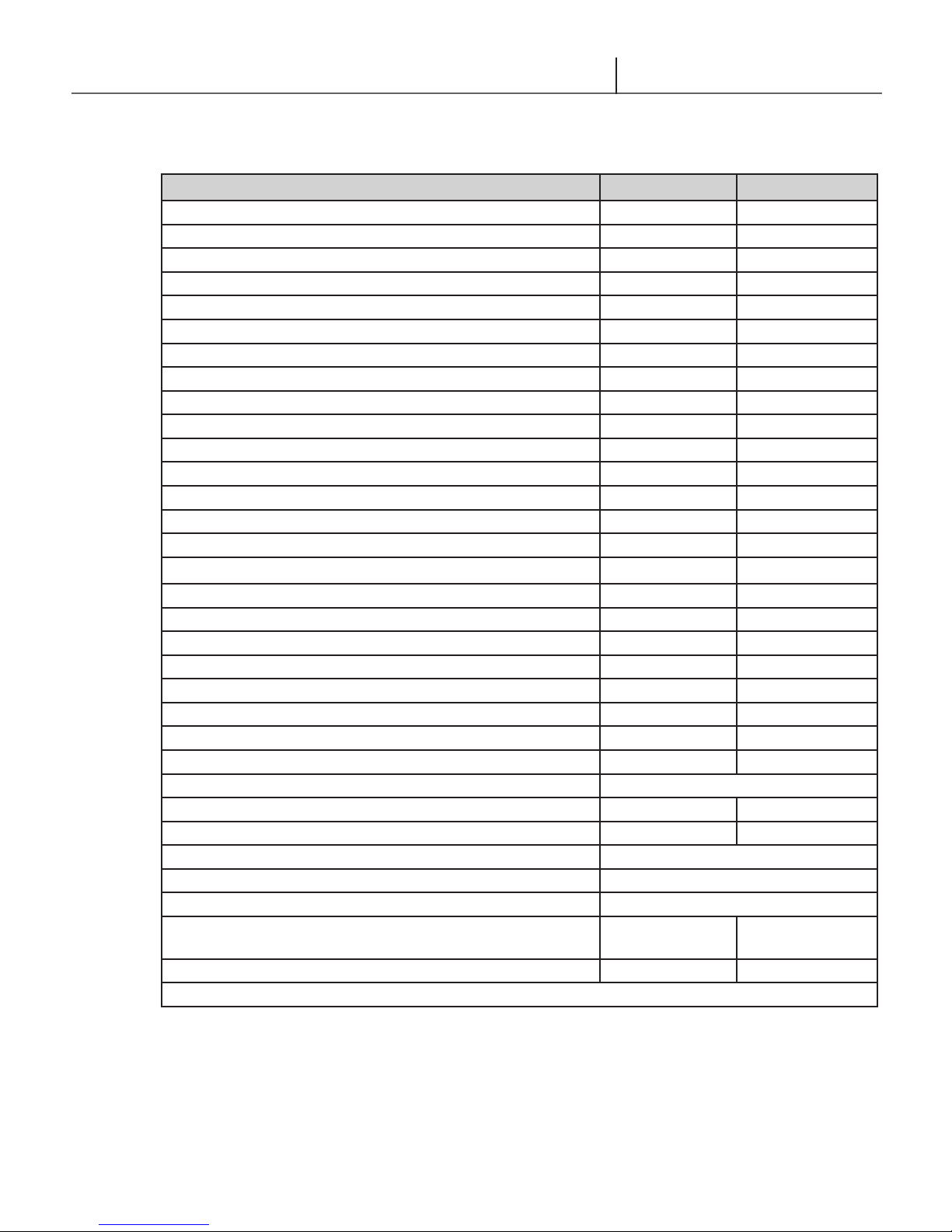
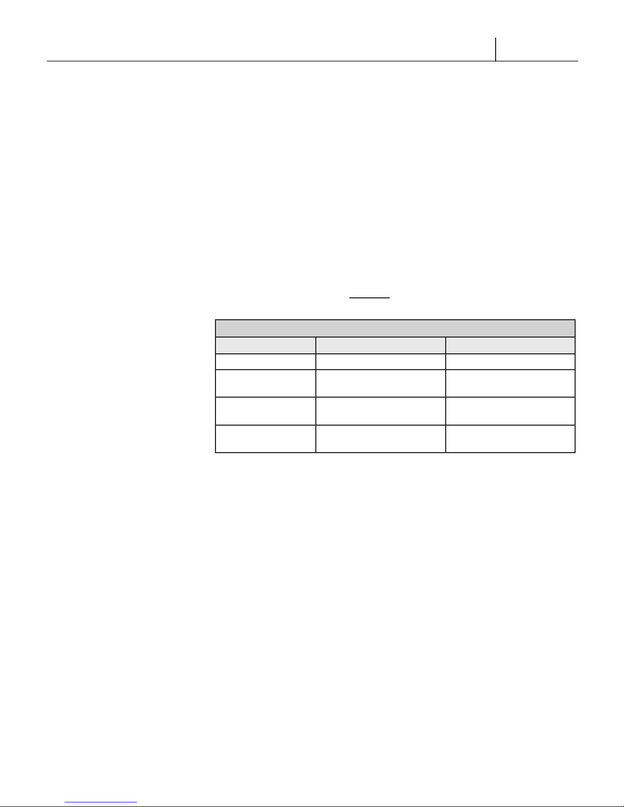
The temperature at which injury occurs varies with the person's age and time of exposure.
Water temperature over 125°F/52°C can cause severe burns instantly or death from scalding.
The slower response time of disabled persons increases the hazards to them. Never allow small children
to use a hot water tap, or to draw their own bath water. Never leave a child or disabled person unattended in a bathtub or shower.
Installation & Operating Instructions
DANGER
The appliance should be located in an area where the general public does not have access to the
temperature control.
Lower water temperatures should be used to avoid the risk of scalding. It is further recommended, in all
cases, that the domestic water temperature be set for the lowest temperature which satisfies the user’s
hot water needs. This will also provide the most energy efficient operation of the water heater and
minimize scale formation in the heat exchanger, thus prolonging the life of the unit.
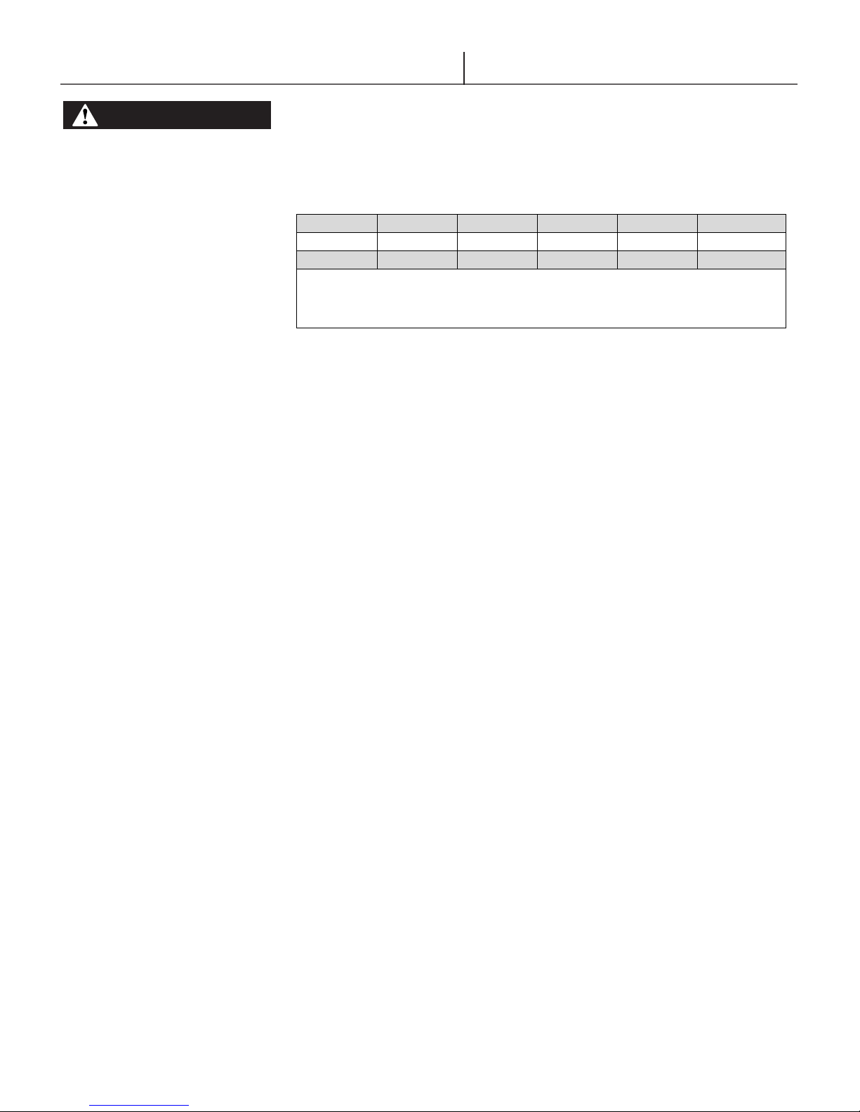
Setting the domestic hot water temperature at 120°F
jurisdictions require settings at specific lower temperatures. The table below shows the approximate
time-to-burn relationship for normal adult skin.
Hot water temperatures required for automatic dishwasher and laundry use can cause scalds and burns
resulting in serious personal injury and/or death.
/49°C will reduce the risk of scalds. Some
Table - Risks of Scalds
Temperature
Setting
Over 170°F/77°C
160°F/71°C
150°F/66°C
140°F/60°C
130°F/54°C
120°F/49°C or less
Time to Produce 2nd, 3rd
Degree Burns on Adult Skin
Nearly instantaneous
About 1/2 second
About 1-1/2 seconds
Less than 5 seconds
About 30 seconds
More than 5 minutes
To protect against injury, installing a tempering valve in the domestic hot water supply is
recommended. This valve will reduce point of discharge temperature by mixing cold and hot
water in branch supply lines. Such valves are available from the local plumbing supplier.
8
Glow Brand C95 & C140
General Information
DANGER
Read and understand this
entire document prior to
proceeding with the
installation of the Glow Combi
Boiler. Failure to follow the
instructions outlined in this
document will result in
property damage, serious
injury or death.
WARNING
Failure to have the boiler
properly serviced and
inspected on a regular basis by
a qualied service technician
may result in property damage,
serious injury or death.
1.2 General information
1.2.1 General Installation Requirements
The installation of your Glow Brand combination boiler must conform to the
requirements of this manual, your local authority, and the National Fuel Gas Code
ANSI Z223.1 and or CAN/CGA B149 Installation Codes. Where required by the
Authority, the installation must conform to the standard for “Controls and Safety
Devices for Automatically Fired Boilers ANSI/ASME CSD-1.
This document pertains to the correct instruction and installation of the Glow
Brand Combination Boilers C95 and C140. The instructions detailed in this
document supersede any and all previous instructions provided by Glow Brand
Manufacturing, written or otherwise. Each unit is provided with an Installation
Manual and a User Information Manual
1.2.2 User Responsibilities
The Glow Combi Boiler must be installed and serviced by a qualied service
technician and must be serviced and inspected annually when operating in
normal residential applications. Demanding applications or extreme conditions
(i.e. commercial) may require more frequent service and inspection. As the User/
Owner of this equipment, you are responsible for ensuring the maintenance is
performed at the required intervals; see Section 14.2- Annual Maintenance and
Inspection.
WARNING
Failure to keep the Vent and
Combustion Air-inlet clear of
ice, snow, and other debris
may result in property damage,
serious injury, or death.
DANGER
Failure to use the appropriate
gas as listed on the rating
plate when operating the Glow
Combi Boiler may result in
extremely dangerous burner
operation leading to property
damage, serious injury or
death. Always ensure the type
of gas being used corresponds
with what is listed on the
rating plate
1.2.3 Installer Responsibilities
A qualied installer is a licensed person who had the appropriate training and a
working knowledge of the applicable codes, regulations, tools, equipment and
methods necessary to install a boiler. The installer assumes all responsibility
for a safe installation and that it meets the requirements of the boiler instruction
manuals, as well as National and local installation codes. It is also the installer’s
responsibility to inform the User/Owner of their obligation with respect to the
description under “User Responsibilities”. Failure to follow this warning could
result in re, serious injury, or death
Natural Gas to Liqueed Petroleum (Lp) conversions kits are not available.
The materials used, such as copper, brass, stainless steel, etc., form a compact,
homogeneous, highly functional unit that is easy to install and simple to operate.
In its simplicity, the wall-mounted appliance is equipped with all the appropriate
accessories required to make it a fully independent combi boiler capable of
satisfying domestic hot water production and central heating (maximum set
point of 60°C/140°F) needs if installed. All combi boilers are fully inspected. This
manual must be kept in a safe place and must accompany the water heater at all
times.
Glow Brand will not be held responsible for any misinterpretation of this manual.
Glow Brand will not be held responsible for the consequences in the case of
non-observance of the instructions contained in this manual or in the case where
actions not specically described herein are undertaken.
9
Glow Brand C95 & C140
ELEVATIONS
2000 ft [610 m]
3000 ft [914 m]
4000 ft [1219 m]
4500 ft [1372 m]
5000 ft [1524 m]
In Canada
1
de-rate by 10%
de-rate by 10%
de-rate by 10%
de-rate by 10%
de-rate % may vary
In USA 2 -
de-rate by 12%
de-rate by 16%
de-rate by 18%
de-rate by 20%
Notes:
1
Canada: Altitudes between 200-4500 ft [610-1372 m], de-rate by 10%. Consult local authorities for de-rating capacities for altitudes above 4500
ft [1372 m].
2
USA: De-rate capacity by 4% for every 1000 ft [305 m], if altitude is over 2000 ft [610 m].
Installation & Operating Instructions
WARNING
Combustion – At elevations
above 2000 feet, the
combustion of the boiler must
be checked with a calibrated
combustion analyzer to ensure
safe and reliable operation. It
is the Installers responsibility
to check the combustion and
to adjust the combustion in
accordance to Section 9.0.
Failure to follow these
instructions may result in
property damage, serious
injury, or death.
1.2 High Altitude Operations
The Glow Combi boiler is designed to operate at its maximum listed capacity
in installations less than or equal to 2000 ft [610 m] above Sea Level. Since
the density of air decreases as elevation increases, maximum specied capacity
should be de-rated for elevations above 2000 ft [610 m] in accordance with
Table 1.1.
Table 1.1: De-rate % High Altitudes
10
Glow Brand C95 & C140
Domestic Input – Min MBH (KW) 9 (2.6) 13 (3.8)
Domestic Input – Max MBH (KW) 97 (28.4) 139 (40.7)
Domestic Output – Min MBH (KW) 8.4 (2.5) 14.1 (4.1)
Domestic Output – Max MBH (KW) 92 (26.9) 134 (39.3)
Central Heating Input – Min MBH (KW) 9 (2.6) 13 (3.81)
Central Heating Input – Max MBH (KW) 44 (12.9) 71 (20.8)
Central Heating Output – Min MBH (KW) 8.4 (2.5) 14.1 (4.1)
Central Heating Output – Max MBH (KW) 40.8 (11.9) 66 (19.3)
A.F.U.E 94% 94%
Min Gas Pressure (Nat. Gas) – inch w.c. 3.5 3.5
Max Gas Pressure (Nat. Gas) – inch w.c. 10.5 10.5
Power (120Vac/60Hz) - Watts @ full re with internal pump 180 198
Expansion tank water content – USG (Liters) 1.6 (6) 1.6 (6)
Min boiler ow rate – Usgpm (lpm) 2.2 (8.3) 5.3 (20.0)
Min Operating Pressure – Space Heating - psig 10 10
Max Operating Pressure – Space Heating - psig 30 30
Technical Characteristics
2. Technical Characteristics
2.1 Technical Data
Specication C95 C140
Min Operating Pressure – Domestic Hot Water - psig 30 30
Max Operating Pressure – Domestic Hot Water - psig 150 150
Min water Temperature - Space Heating - °F (°C) 95 (35) 95 (35)
Max water Temperature – Space Heating - °F (°C) 176 (80) 176 (80)
Min water Temperature – Domestic Hot Water - °F (°C) 104 (40) 104(40)
Max water Temperature – Domestic Hot Water - °F (°C) 140 (60) 140 (60)
Min ow rate to activate DHW – Usgpm (lpm) 0.5 (1.89) 0.5 (1.89)
Max ow rate DHW– Usgpm (Lpm)1 @77°F rise 2.4 (9) 3.7 (14)
Vent/Air-Intake Pipe Diameter, inches (mm) 2 (51) or 3 (76)
Max equivalent vent length 2" (each side) - ft 100 60
Max equivalent vent length 3" (each side)- ft 125 125
CH Water Connections - NPT, in. 3/4
DHW Connections – NPT, in 1/2
Gas Connection - NPT, in. 3/4
Dimensions H x W x D - inches (mm) 31.2 x 16.9 x 14.0
(81.3 x 430 x356)
Weight (empty) – lbs (Kg) 105 (47.6) 125 (56.7)
1
With restrictor installed. High ow rates can be achieved by changing the ow restrictor.
Table 2.1: Unit Specications
31.2 x 16.9 x 18.0
(81.3 x 430 x 457)
11

Glow Brand C95 & C140
31.2
2.2 Unit Dimensions
16.9
6.8
Installation & Operating InstructionsInstallation & Operating Instructions
5.5
Figure 2.1 - Glow C95 Dimensions
5.6
EXHAUST
VENT
LEGEND
Gas Inlet 3/4” NPT
CH Outlet 3/4” NPT
CH Inlet 3/4” NPT
DHW Inlet 1/2” NPT
DHW Outlet 1/2” NPT
Condensate Outlet 3/4” I.D.
16.9
6.8
5.5
AIR
INTAKE
14.0
4.4
1.7
CONDENSATE
OUTLET
4.7
2.0
2.6
SUPPLY DHW
1.9
3.2
RELIEF
FIXTURE
CH
VALVE
6.3
GAS
SUPPLY
DCW
RETURN
2.62.6 5.2
CH
Figure 2.2 - Glow C140 Dimensions
31.2
5.6
EXHAUST
VENT
LEGEND
Gas Inlet 3/4” NPT
CH Outlet 3/4” NPT
CH Inlet 3/4” NPT
DHW Inlet 1/2” NPT
DHW Outlet 1/2” NPT
Condensate Outlet 3/4” I.D.
AIR
INTAKE
18.0
5.8
0.4
CONDENSATE
OUTLET
6.1
2.0
2.6
SUPPLY DHW
1.9
3.2
RELIEF
VALVE
FIXTURE
CH
2.6
6.3
GAS
SUPPLY
DCW
5.2 2.6
CH
RETURN
12
Glow Brand C95 & C140
PRESSURE DROP (PSI)
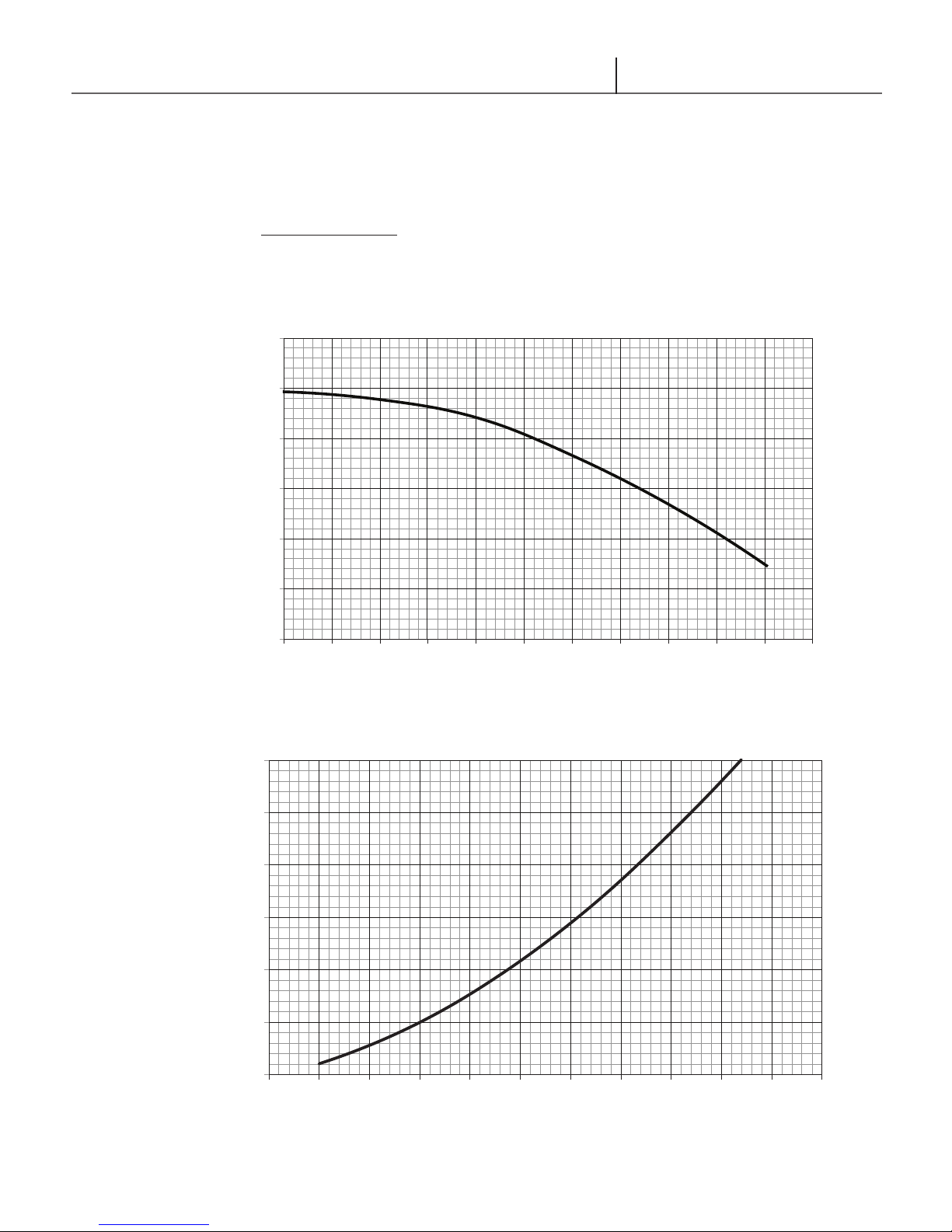
2.3.1 Head Calculation
Example: C95 Target ow of 5 gpm
Figure 2.3 indicates 25.5 ft head available at the desired ow of 5 gpm. Figure 2.4 indicates the
pressure drop in the heat exchanger to be 4.4 psi (10.2 ft) at the target ow of 5 gpm.
Therefore 25.5 - 10.2 = 15.3 ft available for piping and heating device pressure drop.
The C140 unit is supplied with a factory low loss header for eld installation. Therefore external head
is provided by the eld supplied secondary loop circulating (CH) pump.
35
30
25
20
Technical Characteristics
2.3 Unit Performance
C95 CENTRAL HEATING PUMP CURVE
Figure 2.3
HEAD (FEET)
15
10
0
0 1 2 3 4 5 6 7 8 9 10 11
WATER FLOW (GPM)
C95 CENTRAL HEATING PRESSURE DROP VS WATER FLOW
12
10
8
6
4
2
0
Figure 2.4
0 1 2 3 4 5 6 7 8 9 10 11
HEATING WATER FLOW (GPM)
13
Glow Brand C95 & C140
0 1 2 3 4
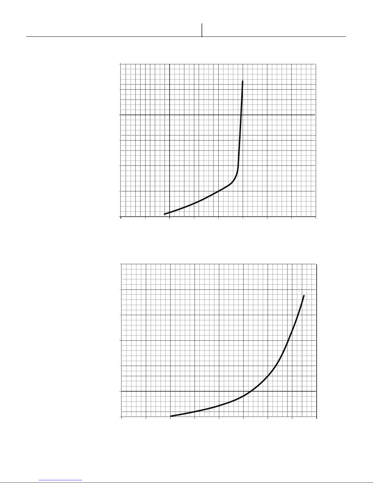
PRESSURE DROP (PSI)
0 1 2 3 4
PRESSURE DROP (PSI)
60
50
40
30
20
10
Installation & Operating InstructionsInstallation & Operating Instructions
C-95 DOMESTIC WATER PRESSURE DROP VS FLOW
(2.4 GPM FLOW LIMITER)
Figure 2.5
0
DHW WATER FLOW (GPM)
C-140 DOMESTIC WATER PRESSURE DROP VS FLOW
(3.7 GPM FLOW LIMITER)
60
50
40
30
20
10
0
Figure 2..6
14
DHW WATER FLOW (GPM)
Glow Brand C95 & C140
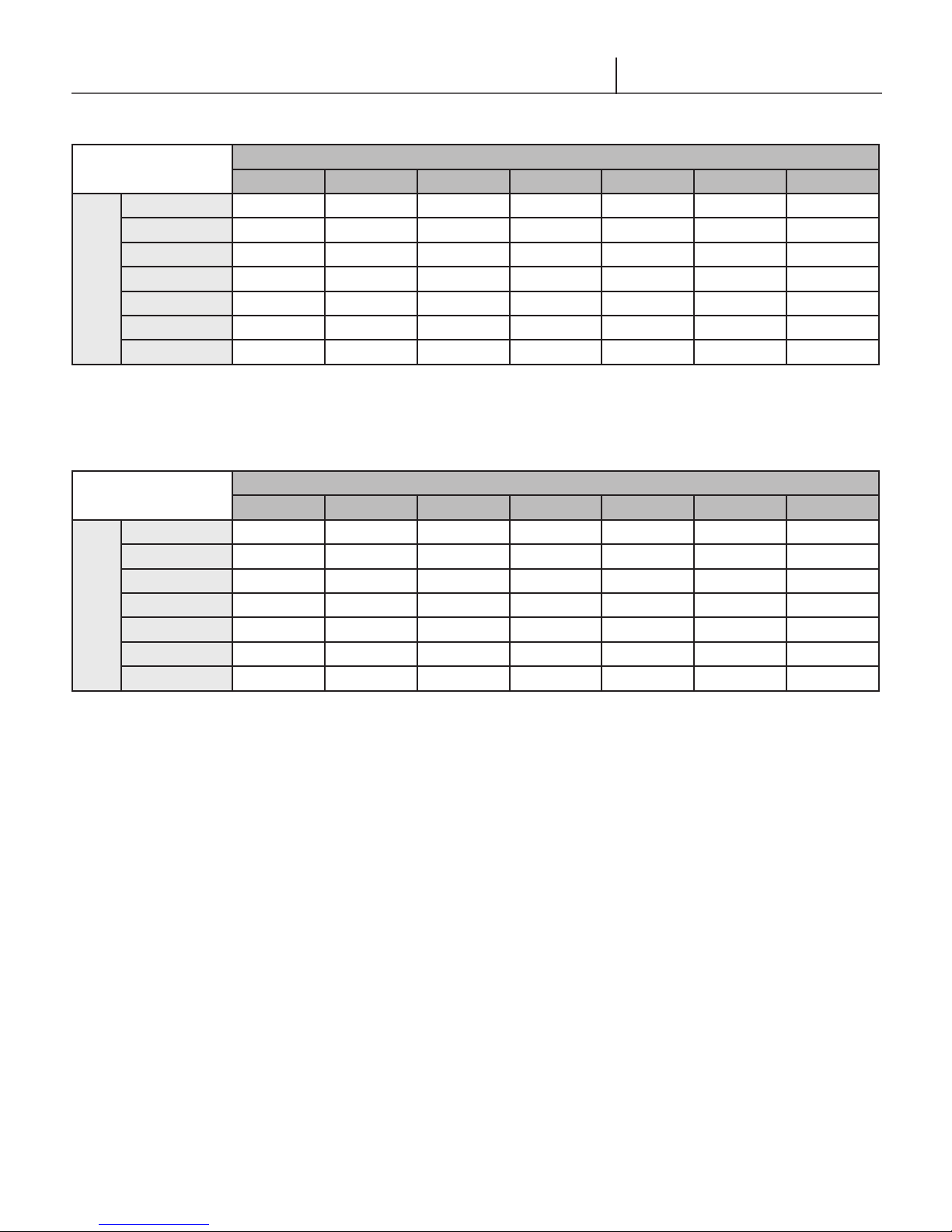
40 45 50 55 60 65 70
2.7 2.9 3.1 3.4 3.7 4.1 4.7
2.5 2.7 2.9 3.1 3.4 3.7 4.1
2.3 2.5 2.7 2.9 3.1 3.4 3.7
2.2 2.3 2.5 2.7 2.9 3.1 3.4
2.1 2.2 2.3 2.5 2.7 2.9 3.1
2.0 2.1 2.2 2.3 2.5 2.7 2.9
1.9 2.0 2.1 2.2 2.3 2.5 2.7
40 45 50 55 60 65 70
3.8 4.1 4.5 4.9 5.4 6.0 6.7
3.6 3.8 4.1 4.5 4.9 5.4 6.0
3.4 3.6 3.8 4.1 4.5 4.9 5.4
3.2 3.4 3.6 3.8 4.1 4.5 4.9
3.0 3.2 3.4 3.6 3.8 4.1 4.5
2.8 3.0 3.2 3.4 3.6 3.8 4.1
2.7 2.8 3.0 3.2 3.4 3.6 3.8
Outlet Water
Temperature (°F)
Table 2.2: C95
Outlet Water
Temperature (°F)
Table 2.3: C140
110
115
120
125
130
135
140
110
115
120
125
130
135
140
Technical Characteristics
C95 Domestic Hot Water Flow vs. Temperature Rise
Inlet Water Temperature (°F)
C140 Domestic Hot Water Flow vs. Temperature Rise
Inlet Water Temperature (°F)
15
Glow Brand C95 & C140
Installation & Operating InstructionsInstallation & Operating Instructions
3. Storage, Handling & Installation
3.1 Storage
The Glow Combi Boiler should be stored in the horizontal position with no more
than three units to a stack; Ensure that the units are stored in dry conditions and
the temperature does not drop below 0°C/32°F when in storage.
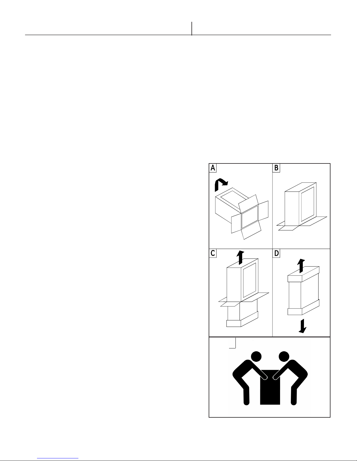
3.2 Unpacking
• The materials (cardboard) used for packing the appliance are fully recyclable.
• It is recommended that the packing material is only removed prior to installing
the unit. The manufacturer will not be held responsible for damage caused by
incorrect storage of the product.
• Packing materials (plastic bags, polystyrene, etc.) must not be left within
reach of children, in that these items represent a potential hazard.
A. Place the packed appliance
on the oor (see g. 3.1)
making sure that the unit is
in its upright position. Open
out the four aps of the box.
B. Rotate the packed
appliance 180° so that the
top is upside down while
manually supporting it from
underneath.
C. Lift the box and remove the
foam packaging.
D. Firmly grip the unit. Lay the
unit on its back away from
the work area and continue
with the installation.
E. Two people are required to
safely lift this boiler onto the
wall mounting bracket.
E
16
Figure 3.1 - Unpacking the Combi Boiler
Glow Brand C95 & C140
A
D C E
F
B
A D
44 24
12
12
C
E F
B
16.5
WARNING
Water or ood damaged
components must be replaced
immediately with new factory
approved components as
failure to do so may result in
property damage, serious
injury, or death.
WARNING
This boiler must not be
installed on carpeting as
failure to do so may result in
property damage, serious
injury, or death.
Storage, Handling & Installation
3.3 Boiler Location
In all cases, the Glow Combi Boiler must be installed indoors in a dry location
where the ambient temperature must be maintained above freezing. The gas
components must be protected from dripping and or spraying water. Consider
the proximity of system piping, gas and electrical supply, drain for condensate
disposal, and proximity to vent termination when determining the best boiler
location.
If the Glow Combi Boiler is installed in an unheated area it is recommended to
leave the unit continually powered in order to ensure the frost protection function
is active.
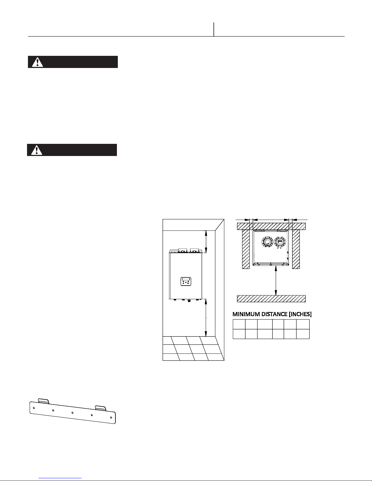
In order to allow access to the interior of the unit for maintenance purposes, it
is important that the minimum distances indicated are respected. See Fig 3.2:
Minimum Installation Clearances
Clearance to Combustibles:
Minimum clearance from combustible or non combustible construction. (Fig. 3.2)
Front – 0 inches
Sides – 0 inches
Rear – 0 inches
Top – 0 inches
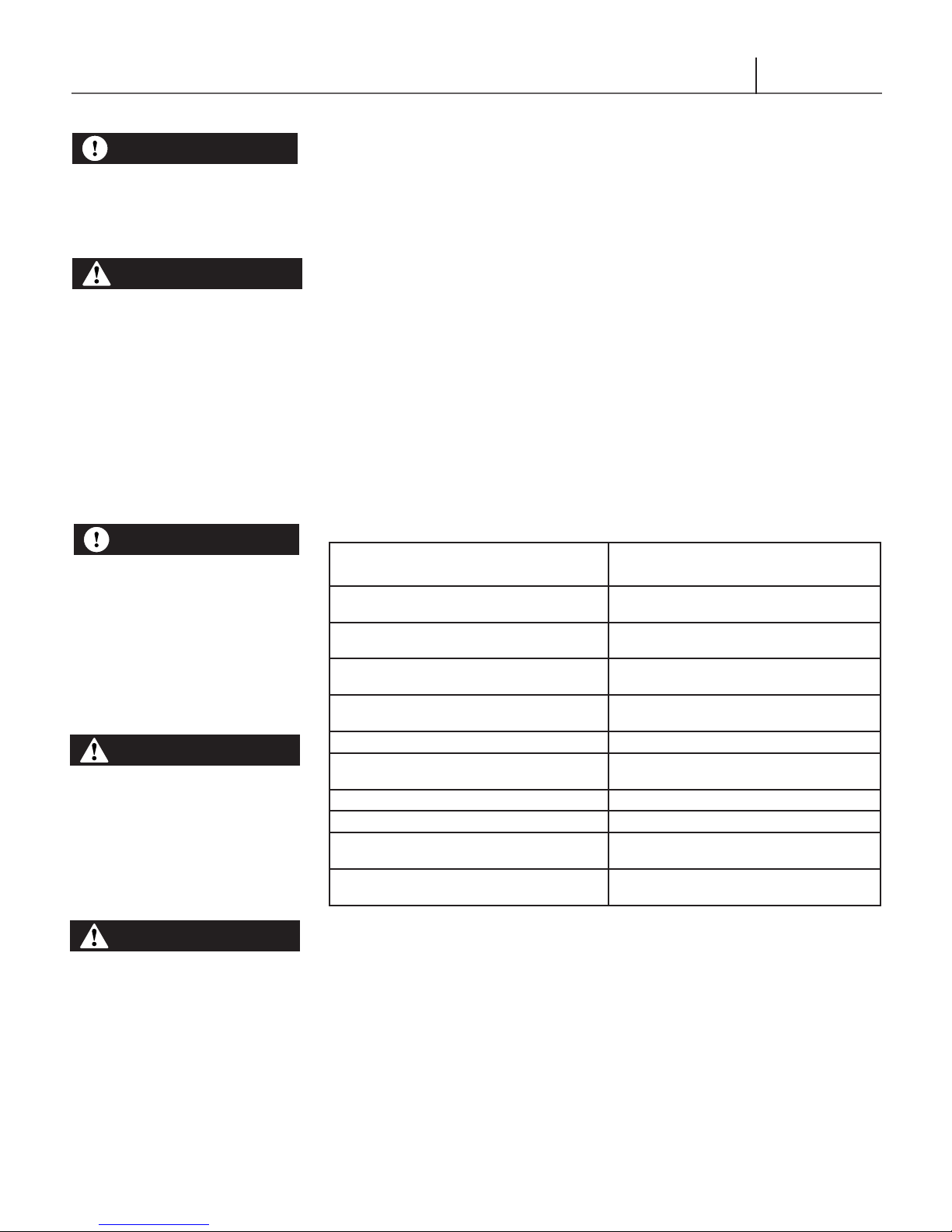
Figure 3.3 - Support Bracket
Figure 3.2 - Minimum Installation Clearances
3.4 Wall Mounting Installations
Included within the packaging of the Glow Combi Boiler is a wall mount support
bracket. Mounting the support bracket (g. 3.3) on a eld supplied ¾” piece of
plywood will add additional structural integrity to the installation. Make sure the
supplied wall mounting support bracket is anchored to a structure capable of
supporting the weight of the boiler and attached piping when lled with water.
For mounting on a cement wall, use appropriately sized masonry anchors or
equivalent. Two people are required to safely lift this boiler onto the wall support
mounting bracket.
17

Glow Brand C95 & C140
Installation & Operating Instructions
Installation & Operating Instructions
DANGER
The ue exhaust and
combustion air intake are to be
piped separately. The Glow
Combi Boiler cannot share a
common ue exhaust or
combustion air intake with
multiple appliances. Failure to
comply may result in property
damage, serious injury, or
death.
DANGER
Do not install the Glow Combi
Boiler into a common venting
system with any other
appliances. Failure to comply
with this warning may cause
ue gas spillage and leech
carbon monoxide emissions
into the surrounding air
resulting in serious injury or
death.
4. Venting
4.1 General Venting
The Glow Combi Boiler is certied as a “Category IV” boiler requiring a “Special
Venting System” designed for pressurized venting. The exhaust vent must be piped
to the outdoors, using the vent materials and rules outlined in this section. Under
no conditions may this unit vent gases directly into a masonry chimney, unless it
is vacant, and utilizes the approved venting material and rules described in this
section. Venting into a masonry chimney is only acceptable when the chimney is
no longer being used for its initial intended purpose therefore considering it a chase
for the exhaust and combustion air vent pipe.
4.2 Removing an Existing Boiler from Common Venting System
Upon removal of an existing boiler, the following steps shall be followed for
each boiler remaining in the common venting system; prior to commencing this
procedure, shutdown all boilers remaining in the common venting system.
Steps to Removing an Existing Boiler:
When an existing boiler is removed from a common venting system, the common
venting system is likely to be too large for proper venting of the remaining boilers
connected to it. Instructions have been provided on how to remove the existing
boiler and how to resize the remaining venting system. Failure to follow these
instructions may result in property damage, serious injury or death.
1. Seal any unused openings in the common venting system.
2. Visually inspect the venting system for proper size and horizontal pitch and
determine there is no blockage or restriction, leakage, corrosion and other
deciencies which could cause an unsafe condition.
3. Insofar as is practical, close all building doors and windows and all doors
between the space in which the appliances remaining connected to the
common venting system are located and other spaces of the building. Turn
on clothes dryers and any appliance not connected to the common venting
system. Turn on any exhaust fans, such as range hoods and bathroom
exhausts, so they will operate at maximum speed. Do not operate a summer
exhaust fan. Close replace dampers.
4. Place in operation the appliance being inspected. Follow the lighting
instructions. Adjust thermostat so appliance will operate continuously.
5. Test for spillage at the draft hood relief opening after 5 minutes of main
burner operation. Use the ame of a match or candle, or smoke from a
cigarette, cigar or pipe.
6. After it has been determined that each boiler remaining connected to the
common venting system properly vents when tested as outlined above, return
doors, windows, exhaust fans, replace dampers and any other gas burning
boiler to their previous condition of use.
7. Any improper operation of the common venting system should be corrected
so the installation conforms to the National Fuel Gas Code, ANSI Z223.1/
NFPA 54 and/or Natural Gas and Propane Installation Code, CAN/CSA
B149.1. When resizing any portion of the common venting system, the
common venting system should be resized to approach the minimum size
as determined using the appropriate tables in Chapter 13 of the National
Fuel Gas Code, ANSI Z223.1/NFPA 54 and/or Natural Gas and Propane
Installation Code, CAN/CSA B149.1.
18
Glow Brand C95 & C140
NOTICE
The boiler shall be located so
as not to interfere with proper
circulation of combustion,
ventilation, and dilution air
WARNING
Make up air requirements for
the operation of exhaust fans,
kitchen ventilation systems,
clothes dryers, and replaces
shall be considered in
determining the adequacy of a
space to provide combustion
air requirements. Failure to
ensure adequate make up air
to all appliances may result in
personal injury or death
Venting
4.3 Installation Using Indoor Combustion Air
When the installation uses Indoor Combustion Air (i.e. piping is not directly
connecting the appliance air-inlet tting to the outdoors), provisions for
combustion and ventilation air, in accordance with section “Air for Combustion
and Ventilation,” of the National Fuel Gas Code, ANSI Z223.1/NFPA 54 (U.S.),
or Clause 8.2, 8.3 or 8.4 of Natural Gas and Propane Installation Code, CAN/
CSA B149.1 (Canada), or applicable provisions of the local building codes, must
be adhered to.
4.3.1 Contaminated Make-Up Air Will Damage the Unit
Do not to operate the combi boiler in an area that is or will be under construction
or renovation. Combustion air containing dust, debris or air-borne contaminants
will drastically increase the required maintenance and may cause a corrosive
reaction in the Heat Exchanger which could result in premature failure, re, serious
injury, or death. The Glow Brand Manufacturing Warranty will not cover damage
and premature wear caused to the unit due to installation in a contaminated
environment.
All of the exhaust venting connections must be leak checked with a soap solution
upon initial startup of the combi boiler. Any leaks must be repaired before
continuing operation of the unit. Warranty will not be available if the unit is used
for construction heat.
NOTICE
It is BEST PRACTICE to pipe
the combustion air-inlet
directly to the outdoors
(Direct Vent installation) to
avoid contamination often
contained in indoor air.
WARNING
Do not store or use gasoline or
other ammable vapors and
liquids in the vicinity of this or
any other appliance. Failure to
follow instructions may result
in serious injury or death.
WARNING
Use of cellular core Schedule
40 PVC (ASTM F891), cellular
core CPVC, or Radel
(polyphenylsulfone) in nonmetallic venting systems is
prohibited. Covering nonmetallic vent pipe and ttings
with thermal insulation is
prohibited.
Products to Avoid Contaminated Sources to
Avoid
Antistatic fabric softeners, bleaches, detergents,
cleaners
Perchloroethylene (PCE), hydrocarbon based
cleaners
Chemical fertilizer, herbicides/pesticides, dust,
methane
Paint or varnish removers, cements or glues,
sawdust
Water chlorination chemicals (chloride, uoride) Swimming pools, hot tubs
Solvents, cutting oils, berglass, cleaning
solvents
Refrigerant charge with CFC or HCFC Refrigerant repair shops
Permanent wave solutions Beauty shops
Fixer, hydrochloric acid (muriatic acid), bromide,
iodine
Cement powder, crack ll dust, cellulose, ber
based insulation
Laundry facilities
Dry cleaning facilities
Farms or areas with livestock and manure
Wood working or furniture renishing shops
Auto body or metal working shops
Photo labs, chemical / plastics processing
plants
Concrete plant or construction site
4.4 Venting Guidelines
• Keep the vent system as short and straight as possible.
• Locate the unit as close as possible to the vent termination.
• The vent must not be common vented with any other gas appliance or vent
stack.
• Slope vent upwards towards the termination at a minimum rate of 1/4” per
foot (2% slope).
• Vent termination must be a minimum of 12” above grade or expected snowfall.
• Vent and air intake pipe must be supported at least every 5 feet of horizontal
run and every 5 feet of vertical run.
19
Glow Brand C95 & C140
Installation & Operating Instructions
Installation & Operating Instructions
4.5 Direct Vent Installation
Direct Vent installation dictates that the combustion air-inlet must be piped directly
to the outdoors using the methods described in this section and in accordance
with the National Fuel Gas Code, ANSI Z223.1 (U.S.) or CSA B149.1 (Canada)
and local requirements. Install the entire venting system securely cementing all
ttings. This Glow Combi Boiler uses a 2” or 3” diameter exhaust vent pipe made
up of PVC or CPVC System 636. The air intake pipe uses 2” or 3” diameter pipe
made of Schedule 40 ABS, DWV, PVC, or CPVC materials and in accordance
with all applicable local building codes.
4.5.1 Exhaust Vent Pipe Materials
Use only 2” or 3” solid PVC/CPVC schedule 40 PVC/CPVC or ULC S636 pipe
and ttings. Venting requirements in USA and Canada are different. Consult the
most recent edition of the National Fuel Gas Code (ANSI Z223.1 / NFPA 54) or
CAN/CSA B-149.1 as well as local codes for applicable venting regulations and
restrictions.
For installation in Canada, eld supplied plastic vent piping must comply with
CAN/CSA B-149.1 (latest edition) and be certied to the standard for type BH
Gas Venting Systems. ULC S636 components of this listed system shall not
be interchanged with other vent systems or unlisted pipe/ttings. All plastic
components and specied primers and glues of the certied vent system must be
from a single manufacturer and not intermixed with other system manufacturer’s
vent system parts. The supplied vent adapters are certied as part of the
combination boiler.
Units installed with vertical exhaust, must have an additional condensate drain
installed on the exhaust vent pipe. Fittings must be ULC S636 approved. Schedule
40 PVC/CPVC pipe/ttings have been approved for use on this appliance with
zero clearance to combustibles.
WARNING
Flammable Cements and
Primers – It is the installers’
responsibility to familiarize
themselves with the hazards
associated with explosive
solvents and to take all
precautions to reduce these
risks. Failure to follow these
instructions can cause
explosions, property damage,
injury or death.
All venting must be supported
to reduce strain on piping
joints. The exhaust vent shall
maintain a 1/4” slope upwards
towards the vent termination
outlet. In situations when
excessive amounts of
condensate is being produced
maintaining a 1/2” slope
upwards towards the vent
termination may be required.
4.5.2 Intake Vent Pipe Materials
Schedule 40 PVC, CPVC or ULC S636 pipe and ttings and ABS or DWV pipe
and ttings can be used for combustion air intake on Glow Brand products.
Transition cement must be used if ABS or DWV pipe is connected to the PVC
appliance adapters.
All plastic components and specied primers and glues of the certied vent
system must be from a single manufacturer and not intermixed with other system
manufacturers vent system parts.
The vent for this appliance shall not terminate over public walkways, near soft
vents, crawl spaces or other areas where condensate or vapour could create a
nuisance or hazard or cause property damage or where condensate vapour could
cause damage or could be detrimental to the operation of regulators, relief valves
of other equipment.
4.5.3 Flammable Solvents and Plastic Piping
Due to the extremely ammable characteristics of most glues, cements, solvents
and primers used in the process of joining plastic vent and air-inlet pipe, explosive
solvent vapors must be evacuated from the vent and air-intake prior to start-up.
Avoid using excess cement or primer that may lead to pooling inside the pipe
assembly. Freshly assembled piping assembly should be allowed to cure before
operating the gas red appliance.
20
Glow Brand C95 & C140
Venting
Improper venting of the Glow Combi Boiler can result in excessive levels of carbon
monoxide which can result in severe personal injury or death. This unit must be
vented in accordance with the “Venting of Equipment” section of the latest edition
of the ANSI Z223.1 / NFPA 54 Natural Gas Code and/or the “Venting systems and
air supply for appliances” section of the latest version of the CAN/CSA B149.1
Natural Gas and Propane Installation Code in Canada and in accordance with all
applicable local building codes.
4.5.4 Equivalent Lengths
• Reduce the maximum vent length accordingly for each elbow used.
• Each 2” & 3” 45° elbow equates to 2.5 linear feet of vent pipe.
• Each 2” & 3” 90° short radius elbow equates to 7.5 linear feet of vent pipe.
• Each 2” & 3” 90° long radius elbow equates to 5 linear feet of vent pipe.
• The maximum length listed is for ue exhaust vent only. The intake length
should be equal length.
• The total maximum equivalent vent pipe distance cannot exceed the values
indicated in Table 2.1 for horizontal and vertical venting distance.
• The maximum lengths are including elbows. Exceeding the maximum venting
distances will cause the appliance to malfunction or cause an unsafe condition.
AVAILABLE VENT LENGTHS
MODEL C95 C140
Vent Diameter Size 2” or 3” Diameter 2” or 3” Diameter
Max Equivalent 2” Diameter 100ft
3” Diameter 125ft
Exhaust Vent Schedule 40 System 636
PVC/CPVC
Intake Vent Schedule 40 PVC/CPVC,
ABS, DWV
Table 4.3: Available Vent Lengths
2” Diameter 60ft
3” Diameter 125ft
Schedule 40 System 636
PVC/CPVC
Schedule 40 PVC/CPVC,
ABS, DWV
4.5.5 Termination Options
The venting system of the Glow Combi Boiler may be terminated using eld
supplied piping to construct a “Two-Pipe” termination, alternatively, the venting
may be terminated using a manufacturer approved concentric vent kit.
Sidewall Termination
Due to potential moisture building up along the exterior wall, sidewall venting may
not be the preferred venting option. Refer to roof top venting options.
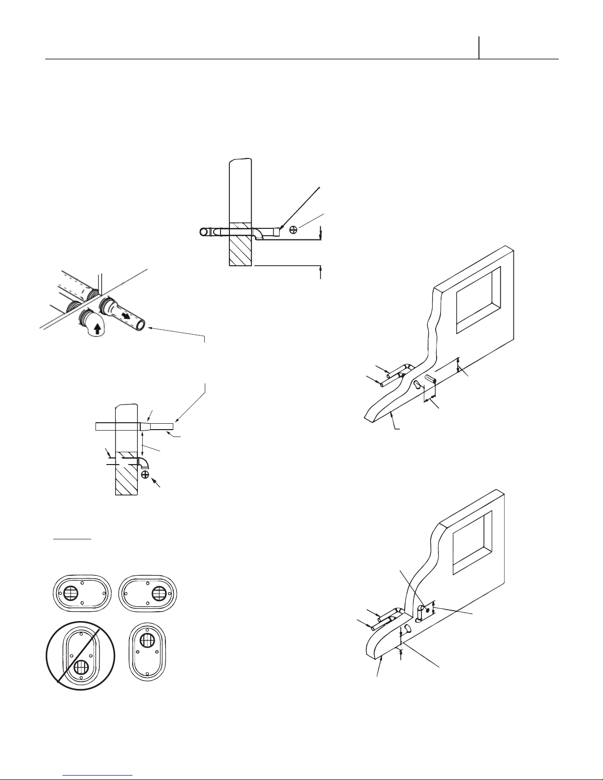
Straight Out Termination – The exhaust vent can terminate straight to an outside
wall. A reducer of 1 pipe diameter smaller can be tted on the exhaust to increase
the velocities of the exiting gases. The reduced diameter pressurizes the exhaust
vent and helps to keep the ue gases from entering the intake. The reduced pipe
diameter of 1 size shall be between 4” to 8” in length.
In the United States (U.S.), provide a minimum of 4 feet (1.22 m) horizontal
clearance from electrical meters, gas meters, gas regulators, and relief equipment
as per National Fuel Gas Code, ANSI Z223.1/NFPA 54. In no case shall the
exit terminal be above or below the aforementioned equipment unless the 4 foot
horizontal distance is maintained.
21

Glow Brand C95 & C140
Installation & Operating Instructions
Installation & Operating Instructions
WARNING
Extra precaution must be taken
to adequately support the
weight of the Vent/Air-inlet
piping in applications using
horizontal or vertical roof
terminations. Failure to follow
these instructions may result
in venting or boiler component
failure resulting in ue gas
spillage leading to property
damage, serious injury or
death.
WARNING
Any time the exhaust vent
passes through an
unconditioned space, care
should be taken to ensure the
vent pipe is insulated in order
limit the amount of condensate
collecting within the vent.
Make certain the system has
been installed in accordance
with the latest version of CAN/
CSA B149.1 Natural Gas and
Propane Installation Code and
in full compliance with all local
codes.
DANGER
Under no circumstances may
an existing chimney or chaseway be used to vent or provide
combustion intake air to a
Glow combi boiler. Failure to
follow these instructions will
result in re, property damage,
serious injury or death.
In Canada, provide minimum horizontal clearance from electrical meters, gas
meters, gas regulators, and relief equipment as per The Canadian Natural Gas
And Propane Installation Code, B149.1.
The vent for this combi boiler shall not terminate over public walkways; or near
soft vents or crawl space vents or other area where condensate of vapor could
create a nuisance or hazard or cause property damage;
Vertical Roof Termination - All terminations that end vertically through the roof
must have an additional condensate tee installed on the vent pipe before the unit.
This condensate line shall include a trap. See Fig. 4.1.
EXHAUST
INTAKE AIR
CONDENSATE
DRAIN
Fig 4.1: Vertical Drain Tee with Trap
EXHAUST
INTAKE AIR
CONDENSATE
DRAIN
4.5.6 Venting Rules and Guidelines
1. Prevailing Winds: Ensure the vent is located where it will not be exposed to
normal prevailing winds.
2. Combustion Air Intake Contamination: Air for combustion must be drawn
from an area free of dust and contaminants. Combustion air containing
chemicals such as chloride, uoride, bromine, iodine or dust and debris will
cause damage of the heat exchanger voiding your Glow Brand Warranty.
3. Vertical Separation: The exhaust outlet must be a minimum of 8” to a
maximum of 24” above the combustion air intake. The combustion air intake
must always be a minimum of 12” plus snow allowance above any surface
that will support snow.
4. Horizontal Separation: The horizontal distance between the intake and
exhaust must be a minimum of 6” center to center.
5. Flue Gas Hazard: The vent for this appliance shall not terminate over public
walkways, near soft vents, crawl spaces or other areas where condensate
or vapour could create a nuisance or hazard or cause property damage.
Condensate vapour could cause damage or could be detrimental to the
operation of regulators, relief valves of other equipment.
22

Glow Brand C95 & C140
Venting
6. Vent Sloping: All exhaust piping must maintain a ¼” per foot upwards
slope towards the outlet of the vent termination. For applications where,
excessive condensation is possible, a ½” per linear foot upward slope is
recommended.
7. Vent Supports: All exhaust and air intake piping shall be secured to the wall
for rigidity. Exhaust and air intake pipe must be supported horizontally and
vertically at a maximum of every 4 feet.
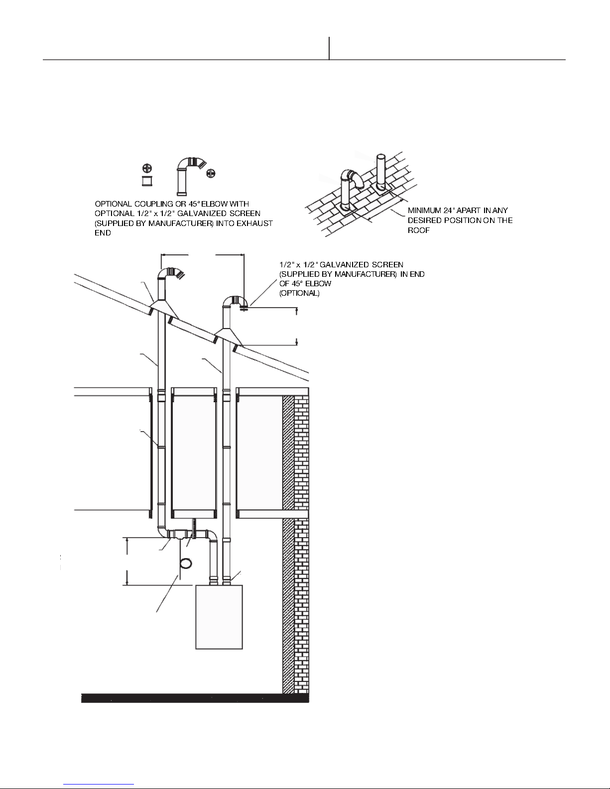
8. Roof Exhaust: In all roof applications the discharge must point away from
the pitch of the roof and must be a minimum 24” apart.
9. Roof Flashing: Install adequate ashing where the pipe enters the roof, to
prevent water leakage.
10. Venting Below Grade: For installations that exit the wall below grade, refer
to the latest version of the CAN/CSA B149.1 Natural Gas and Propane
Installation Code.
11. Vent Screens: Factory supplied vent screens may be installed on the intake
and or exhaust termination. Two ½” by ½” galvanized screens are provided
in a package. Vent screen installation is optional.
12. Condensate Hazard: Do not locate vent over public walkways, driveways
or parking lots. Condensate could drip and freeze resulting in a slip hazard
or damage to vehicles and machinery.
13. Venting Options: Due to potential moisture loading (build-up) along the
exterior wall, sidewall venting may not be the preferred venting option.
14. Wall Thickness: Direct vent terminations are designed to work with any
standard wall thickness. Installation guidelines for min/max wall thickness
are as follows: Min.= 1” [25mm], Max.= 50” [1.27 m].
23
Glow Brand C95 & C140
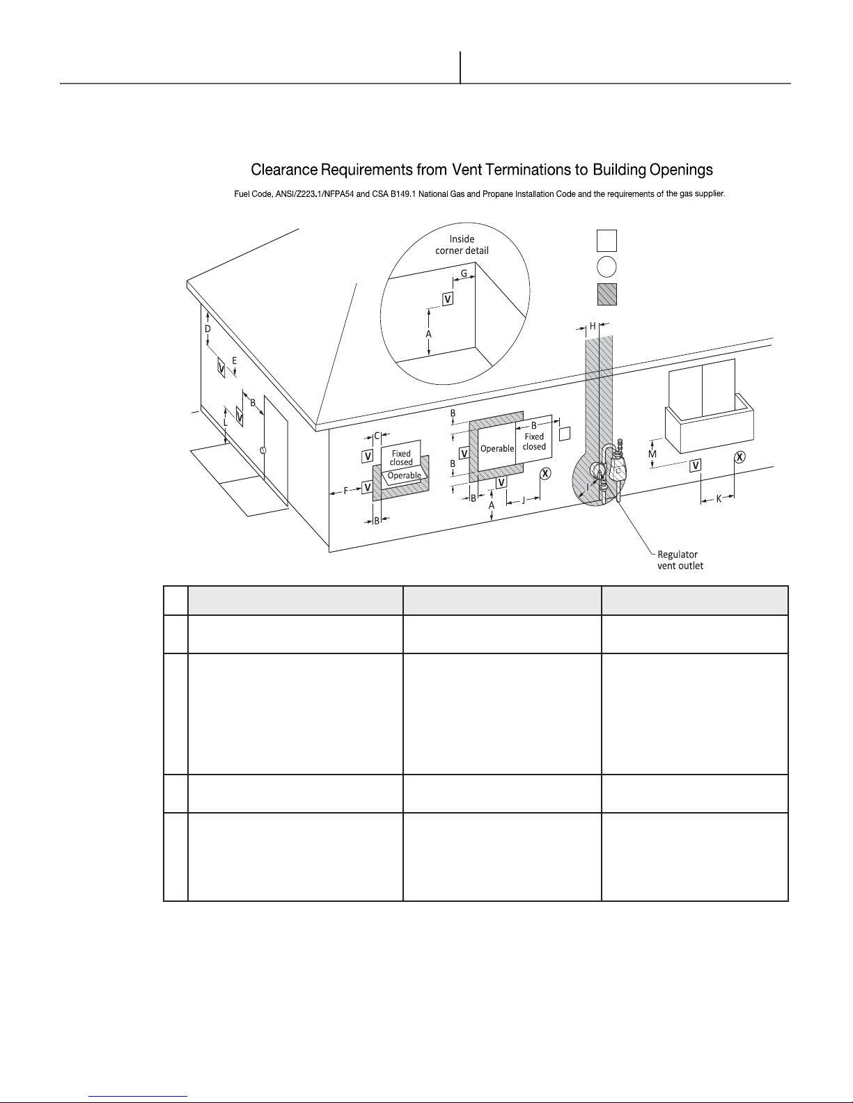
*All clearance requiremnts are in accordance with ANSI Z21.10.3 and the National
V
X
Legend:
= Vent terminal
= Air supply inlet
= Area where terminal is not permitted
Installation & Operating Instructions
Installation & Operating Instructions
4.4 Venting Diagrams
4.4.1 Venting Clearances- Direct Vent
Canadian Installations
A
Clearance above grade,
veranda, porch deck or balcony
B
Clearance to window or door
that may be opened
C
Clearance to permanently closed
window
D
Vertical clearance to ventilated
soft located above the terminal
within a horizontal distance of
2 feet from the center of the
terminal
Table 4.2: Direct Vent Terminal Clearances (continued next page)
12 in (30 cm) 12 in (30 cm)
6 in (15 cm) for appliances
≤ 10,000 BTUh (3kW),
12 in (30cm) for appliances
> 10,000 BTUh (3kW) and
< 100,000 BTUh) (30kW),
36 in (91 cm) for appliances
> 100,000 BTUh (30kW)
1
US Installations
6 in (15 cm) for appliances
≤ 10,000 BTUh (3kW),
9 in (23 cm) for appliances
>10,000 BTUh (3kW) and
≤ 50,000 BTUh) (15kW),
12 in (30 cm) for appliances
> 50,000 BTUh (15kW)
* *
* *
2
24
Glow Brand C95 & C140
Venting
E Clearance to unventilated soft
F Clearance to outside corner
G Clearance to inside corner
H Clearance to each side of
centre line extended above
meter / regulator assembly
I Clearance to service regulator
vent outlet
J Clearance to non mechanical
air supply inlet or combustion
air inlet to any other appliance
Canadian Installations
* *
* *
* *
* *
Above a regulator within
3 ft (91 cm) horizontally of
the vertical center line of
the regulator vent outlet to a
maximum vertical distance of
15 ft (4.5 m)
6 in (15 cm) for appliances
≤ 10,000 BTUh (3kW),
12 in (30cm) for appliances
> 10,000 BTUh (3kW) and
< 100,000 BTUh) (30kW),
36 in (91 cm) for appliances
> 100,000 BTUh (30kW)
1
US Installations
*
6 in (15 cm) for appliances
≤ 10,000 BTUh (3kW),
9 in (23 cm) for appliances
>10,000 BTUh (3kW) and
≤ 50,000 BTUh) (15kW),
12 in (30 cm) for appliances
> 50,000 BTUh (15kW)
2
K Clearance to mechanical air
supply inlet
L Clearance above paved
sidewalk or paved driveway
located on public property
M Clearance under veranda,
porch deck or balcony
Table 4.2: Direct Vent Terminal Clearances
* For clearances not specied in ANSI Z223.1/NFPA 54 or CSA B149.1, one of the following shall be indicated:
A) a minimum clearance value determined by testing in accordance with Clause 5.21, Draft hoods, or
B) a reference to the following footnote:
“Clearance in accordance with local installation codes and the requirements of the gas supplier.”
+ A vent shall not terminate directly above or sidewalk or paved driveway that is located between two single
family dwellings and serves both dwellings.
++ Permitted only if veranda, porch, deck, or balcony is fully open on a minimum of two sides beneath the oor.
Notes:
1) In accordance with the current CSA B149.1, Natural Gas and Propane Installation Code
2) In accordance with the current ANSI Z223.1/ NFPA 54, National Fuel Gas Code
6 ft (1.83 m)
7 ft (2.13 m)
12 in (30 cm)
+
++
3 ft (91 cm) above if within
10 ft (3 m) horizontally
*
*
25
Glow Brand C95 & C140
MINIMU
M
24" APART
IN
ANY
DESIRE
D
POSITION
ON
THE
ROOF
1/2" x 1/2" GALVANIZE
D
SCREEN
(SUPPLIE
D BY
MANUFACTURER)
IN
END
OF 45° ELBOW
(OPTIO
NAL)
OPTIONAL
COUPLING
OR 45°
ELBOW
WITH
OPTIO
NAL 1/2" x
1/2" GALVANIZED
SCREEN
(SUPPLIED
BY
MANUFACTURER)
INTO EXHAUST
END
24" (61 cm)
FLASHING
EXHAUST
PVC
OR
CPVC
SUPPORT
INTAKE
ABS/DWV
PVC/
OR
CPVC
Installation & Operating Instructions
Installation & Operating Instructions
4.4.2 Venting Materials
Vertical Vent Termination-PVC/CPVC Material Only 2” or 3”
Vertical Intake ABS/DWV /PVC or CPVC Material 2” or 3”
12" (18" CANADA)
ABOVE HIGHEST EXPECTED
SNOW LEVEL
THE AIR INLET AND EXHAUST PIPE CAN BE LOCATED
*
IN ANY DESIRED POSITION ON THE ROOF, BUT MUST
ALWAYS BE MINIMUM 24" APART.
A PROPER FLASHING SHOULD BE USED TO SEAL THE
PIPE WHERE IT EXITS THE ROOF.
SLOPE VENT
UPWARDS
TO DRAIN & DISPOSE OF
CONDENSATE
ACCORDING TO LOCAL
CODES
HANGER
STRAP
PVC
ADAPTER
THE VENT SYSTEM MUST TERMINATE SO THAT THE
PROPER CLEARANCES ARE MAINTAINED AS CITED IN
LOCAL CODES OR THE CURRENT EDITION OF THE
NATURAL GAS AND PROPANE INSTALLATION CODE
(CAN/CSA-B-149.1) AND ANSI Z223.1/NFPA54.
PROVIDE SUPPORT FOR ALL PIPE PROTRUDING
THROUGH THE ROOF. ALL PIPING SHOULD BE
SECURED. THE VENT SYSTEM SHOULD BE
SUPPORTED EVERY 5 FEET (1.5m) OF VERTICAL RUN
AND EVERY 5 FEET (1.0m) OF HORIZONTAL RUN. ALL
PIPING AND FITTINGS MUST B
PROCEDURES AS DESCRIBED UNDER VENT
PREPARATION.
WHEN USING A HORIZONTAL SECTION, SLOPE THE
HORIZONTAL VENT 1/4" UPWARDS TOWARDS
TERMINATION
TOWARDS THE
EXHAUST VENT PIPE THROUGH AN UNHEATED
MUST BE INSULATED AS PER LOCAL CODES AND
AUTHORITIES.
ALL VERTICAL EXHAUST VENTING MUST HAVE AN
*
ADDITIONAL CONDENSATE DRAIN. ALL FITTING MUST
BE ULC S636 APPROVED.
FOR EVERY 12" (30 cm) (2% SLOPE)
CONDENSATE
E JOINED BY THE PROPER
DRAIN.
SPACE
26
Glow Brand C95 & C140
Venting
4.4.3 Horizontal Vent Termination
Horizontal Vent Termination-PVC/CPVC Material Only 2” OR 3”
Horizontal Intake ABS/DWV or PVC/CPVC Material 2” OR 3”
EXHAUST PVC/CPVC
OPTIONAL COUPLING
A REDUCER MAY BE USED ON THE
VENT TERMINATION TO INCREASE
THE VELOCITIES OF THE EXITING
GASES AWAY FROM THE INTAKE
THE EXHAUST VENT FITTED WITH
THE REDUCER MAY BY POSITIONED
ABOVE OR BESIDE THE INTAKE PIPE
REDUCER
ABS OR
PVC
MIN. 6” (15 CM)
INSERT 1/2” x 1/2” GALVANIZED SCREEN (SUPPLIED BY
MANUFACTURER) IN END OF 90ELBOW (OPTIONAL).
INTAKE VENT PIPING TO BE SLOPED (DOWN) TOWARD
HEATER TO PREVENT WATER FROM COLLECTING
MIN. 10” (25 CM)
MIN 10"
12” (30cm) ABOVE GRADE
OR EXPECTED SNOW FALL
1/2” x 1/2” GALVANIZED SCREEN
(SUPPLIED BY MANUFACTURER)
INTO THE EXHAUST END (OPTIONAL)
EXHAUST
INTAKE
WINDOW
12” (30cm) ABOVE GRADE
OR EXPECTED SNOW FALL
MIN. 6" (15 cm) CENTER TO CENTER
OUTSIDE WALL
OPTIONAL
LOW PROFILE SIDE WALL
TERMINATION KIT 2” OR 3”
MUST BE ULC S636 APPROVED
EXHAUST
INTAKE
OPTIONAL
SCREEN INTO
90°ELBOW END
OUTSIDE WALL
WINDOW
MIN. 8" (20 cm)
MAX. 24" (60 cm)
12” (30 cm) ABOVE GRADE
OR EXPECTED SNOW FALL
27
Glow Brand C95 & C140
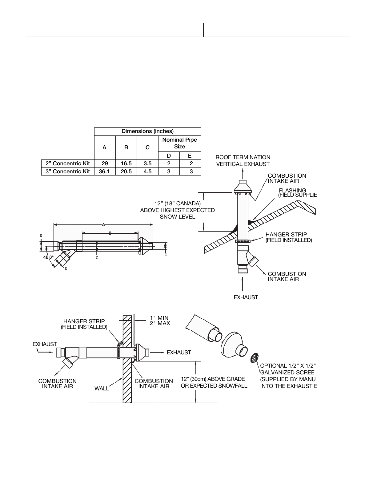
A
2” Concentric Kit 29 16.5 3.5 2 2
3” Concentric Kit
36.1 20.5 4.5 3 3
Installation & Operating Instructions
Installation & Operating Instructions
4.4.4 Concentric Venting Materials
Concentric Vent Termination - 2” or 3” PVC/CPVC
Dimensions (inches)
Nominal Pipe
B C
12” (18” CANADA)
ABOVE HIGHEST EXPECTED
Size
D E
SNOW LEVEL
ROOF TERMINATION
VERTICAL EXHAUST
COMBUSTION
INTAKE AIR
FLASHING
(FIELD SUPPLIED)
EXHAUST
COMBUSTION
INTAKE AIR
HANGER STRIP
(FIELD INSTALLED)
WALL
1" MIN
2" MAX
EXHAUST
COMBUSTION
INTAKE AIR
EXHAUST
12” (30cm) ABOVE GRADE
OR EXPECTED SNOWFALL
HANGER STRIP
(FIELD INSTALLED)
COMBUSTION
INTAKE AIR
OPTIONAL 1/2” X 1/2”
GALVANIZED SCREEN
(SUPPLIED BY MANUFACTURER)
INTO THE EXHAUST END
NOTE: USE ONLY ULC S636 APPROVED CONCENTRIC VENT TERMINATION - 2” or 3” PVC
28
Glow Brand C95 & C140
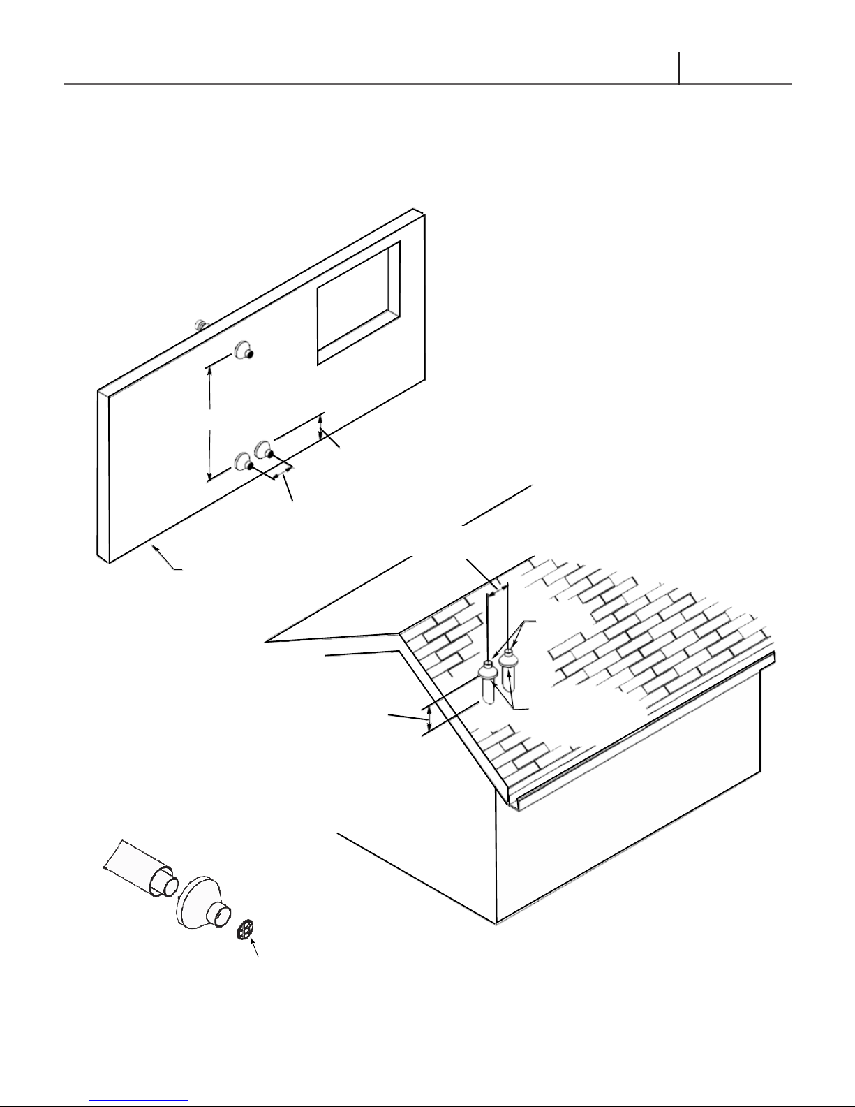
48" MIN.
Venting
4.4.5 Concentric Venting Materials
Concentric Vent Termination - 2” or 3” PVC/CPVC
WINDOW
12" (30 CM) ABOVE
HIGHEST EXPECTED
SNOW LEVEL
MIN 12"
CENTER TO CENTER
OUTSIDE WALL
12" (18" CANADA) ABOVE
HIGHEST EXPECTED
SNOW LEVEL
12" MINIMUM
EXHAUST
COMBUSTION
INTAKE AIR
OPTIONAL 1/2" x 1/2" GALVANIZED SCREEN
(SUPPLIED BY MANUFACTURER)
INTO THE EXHAUST END
29
 Loading...