

Page 1

BUMBLEBEAM™
USER MANUAL
GLOW® Bumble Beam™ 1
Page 2

GLOW® Bumble Beam™ 2
© 2014 GLOW® Professional.
Information subject to change without notice. GLOW® Professional disclaim liability for any injury, damage, direct or indirect loss, consequential or economic loss or
any other loss occasioned by the use of, inability to use or reliance on the information contained in this manual. The Glow logo, the Bumblebeam logo, the GLOW
®
Professional name, the BumbleBeam name and all other trademarks in this document pertaining to services or products by GLOW® Professional or its afliates and
subsidiaries are trademarks owned or licensed by GLOW® Professional
GLOW® Professional •
www.Glow-Lighting.com
Page 3

GLOW® Bumble Beam™ 3
Table of contents
Safety information ..................................................................................................... 4
Introduction ............................................................................................................... 6
Before using the product for the rst time ........................................................ 6
Maximizing lamp life ....................................................................................... 7
Installation ............................................................................................................ 8 - 9
AC Power .................................................................................................................10
Fixture Overview ............................................................................................. 11 - 12
Control Data Link .................................................................................................... 12
Connecting the DMX data Link ............................................................................... 12
Fixture Setup ........................................................................................................... 13
DMX viewer ............................................................................................................. 14
Fixture Settings ....................................................................................................... 14
Lamp Settings ......................................................................................................... 15
Display Settings ...................................................................................................... 15
Manual Settings ............................................................................................... 16 - 17
Callibration .............................................................................................................. 18
Effects ..................................................................................................................... 19
Gobos ..................................................................................................................... 20
Features ................................................................................................................. 21
Maintenance .................................................................................................... 22 - 23
Lamp Replacement ......................................................................................... 24 - 25
Replacing the primary fuse ..................................................................................... 26
Other service and repairs ....................................................................................... 26
Display Menu Settings ..................................................................................... 27 - 30
DMX Chart ....................................................................................................... 31 - 36
Specication ..................................................................................................... 37 - 39
Rev 1.1
Page 4
GLOW® Bumble Beam™ 4
Safety Information
WARNING!
Read the safety precautions in this manual before installing,
operating or servicing this product.
Safety Notes
Read all the following Safety Notes before working with this
product. These notes include important information about the
installation, usage, and maintenance of this product.
This product contains no user-serviceable parts. Any reference to servicing in this User Manual will only apply to
properly trained GLOW
®
Professional certied technicians.
Do not open the housing or attempt any repairs.
All applicable local codes and regulations apply to proper
installation of this product.
Personal Safety
· Avoid direct eye exposure to the light source while the
product is on.
· Always disconnect this product from its power source before
servicing.
· Always connect this product to a grounded circuit to avoid the
risk of electrocution.
· Do not touch this product’s housing during operation
because it may be very hot.
Mounting And
Rigging
· This product is for indoor use only! To prevent risk of re or
shock, do not expose this product to rain or moisture. (IP20)
· Mount this product in a location with adequate ventilation, at
least 20 in (50 cm) from adjacent surfaces.
· Make sure there are no ammable materials close to this
product while it is operating.
· Always carry this product by the handles. Do not carry from
the head.
· When hanging this product, always secure to a fastening
device using a safety cable.
Page 5

GLOW® Bumble Beam™ 5
Safety Information
Power And Wiring
· Always make sure you are connecting this product to the
proper voltage in accordance with the specications in this
manual or on the product’s specication label.
· Never connect this product to a dimmer pack or any rheostat.
· Never disconnect this product by pulling or tugging on the
power cable.
Operation
· Do not operate this product if you see damage to the
housing, lenses, ultraviolet lter, or cables. Have the
damaged parts replaced by an authorized technician at
once.
· Do not cover the ventilation slots when operating to avoid
internal overheating.
· Do not aim this product toward the Sun. The lenses could
concentrate the solar energy and cause internal
overheating.
· The maximum ambient temperature is 120 °F (49 °C). Do
not operate this product at a higher temperature.
· In case of a serious operating problem, stop using this
product immediately
In the unlikely event that your GLOW® product may require service, contact
GLOW® Technical Support.
Page 6

GLOW® Bumble Beam™ 6
Introduction
The GLOW® Professional Bumble Beam™ is a high-performance moving-head
lighting xture equipped with an HRI 2R 132W lamp. It’s compact design makes it
ideal for venue installations, and small to mid sized stage and concerts.
The xture features a rotating and indexing gobo wheel with 14 gobos, a color wheel
with 14 color lters. High grade,smooth mechanical step motors are tted for seam-
less movement of all mechanical parts. The GLOW® Professional Bumble Beam™
also features pan/tilt feedback, coarse and ne control of movement and effects, a
range of built-in movement and effect macros, prism effects, motorized focus, as
well as frost lter and strobe effects.
The xture can be controlled using any DMX-compliant controller as well as auto-
matic mode and sound to light mode.
Before using the product
for the rst time
1. Read ’Safety information’ on page 4 before installing, operating or servicing the
xture.
2. Unpack and ensure that there is no transportation damage before using the
xture. Never attempt to operate a damaged xture.
3. If the xture is not going to be hard-wired to a mains supply, attach a local power
plug to the end of the supplied power cable.
4. Before operating, ensure that the voltage and frequency of the power supply
match the power requirements of the xture.
5. Check the GLOW® Professional Bumble Beam™ website for the most recent
user documentation and technical information about the xture.
Note that whenever AC power is applied to the xture, it will reset all effects and
functions to their home positions. The xture head will move. This process usually
takes around 15 seconds. On hot strike the xture will wait for lamp for a Maximum
of 70 seconds.
Page 7

GLOW® Bumble Beam™ 7
Maximizing lamp life
To obtain maximum operating life from the xture’s discharge lamp:
• Each time you power the lamp on, allow it to warm up for at least 5 minutes
before you power it off.
• Before shutting down power completely, power the lamp off but leave power
applied to the xture for a few minutes so that cooling fans can prevent any
momentary lamp temperature increase caused by heat from surrounding
components.
Page 8
GLOW® Bumble Beam™ 8
Installation
Warning! Read ‘Safety information’ on page 4 before installing
the xture.
The xture is designed for indoor use only and must be used in
a dry location with adequate ventilation. Ensure that none of the
xture’s ventilation slots are blocked and ensure that the xture
is fastened to a secure structure or surface. Do not use the xture
to illuminate surfaces less than 8 m (appx 26ft.) from the xture.
Fastening the xture to a at surface
The xture can be fastened to a hard, xed, at surface that is oriented at any
angle. Ensure that the surface and all fasteners used can support at least 10
times the weight of all xtures and equipment they will support. Fasten the xture
securely. Do not stand it on a surface or leave it where it can be moved or fall over.
If you install the xture in a location where it may cause injury or damage if it falls,
secure it as directed below with a securely anchored safety cable that will hold the
xture if the primary fastening method fails.
Mounting the xture on a truss
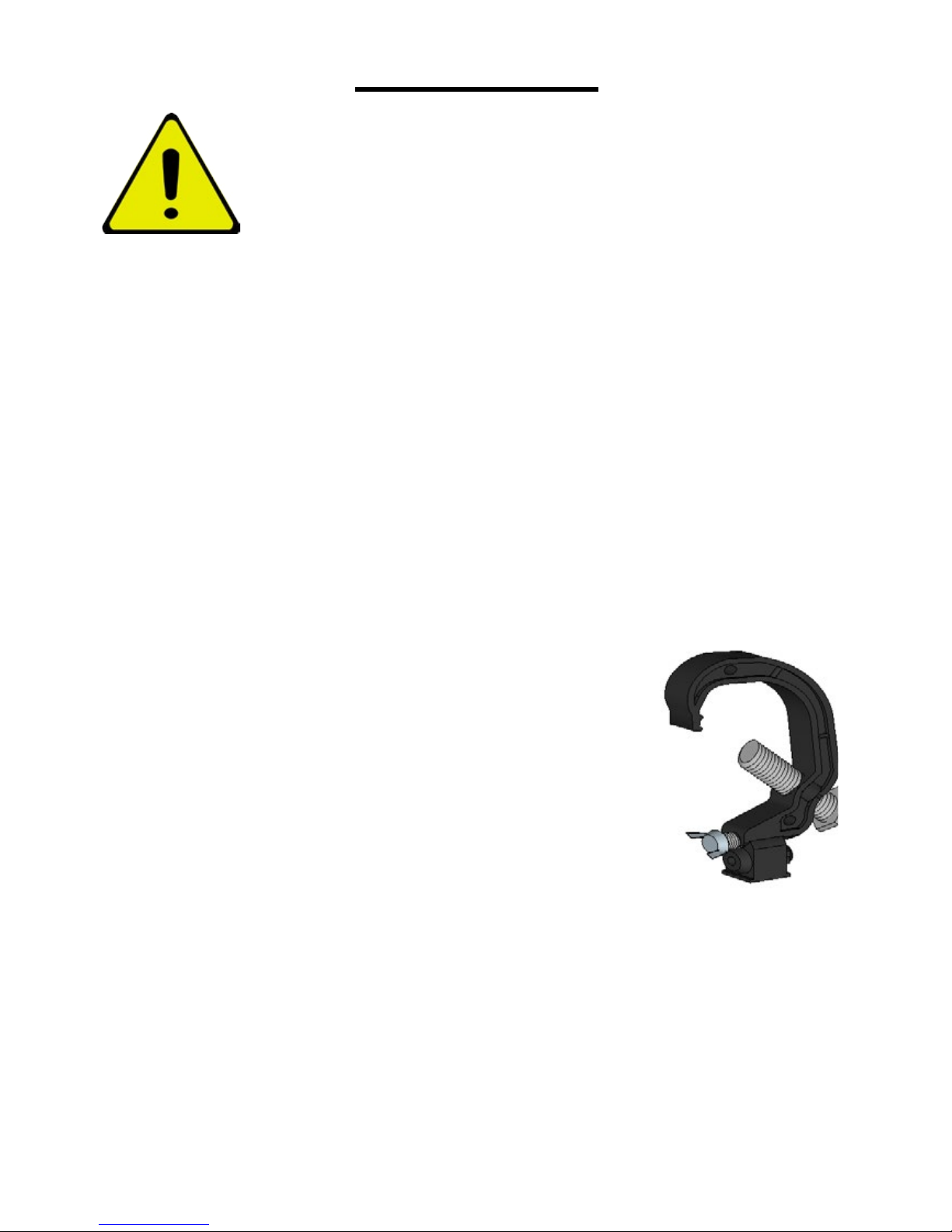
The xture can be clamped to a truss or similar rigging
structure in any orientation. When installing the xture
hanging vertically down, you can use an open-type
clamp such as a G-clamp. When installing in any
other orientation, you must use a half-coupler clamp
that completely encircles the truss or pipe circumfrance.
To clamp the xture to a truss:
1. Check that the rigging structure can support at least 10 times the weight
of all xtures and equipment to be installed on it.
2. Block access under the work area.
Page 9
GLOW® Bumble Beam™ 9
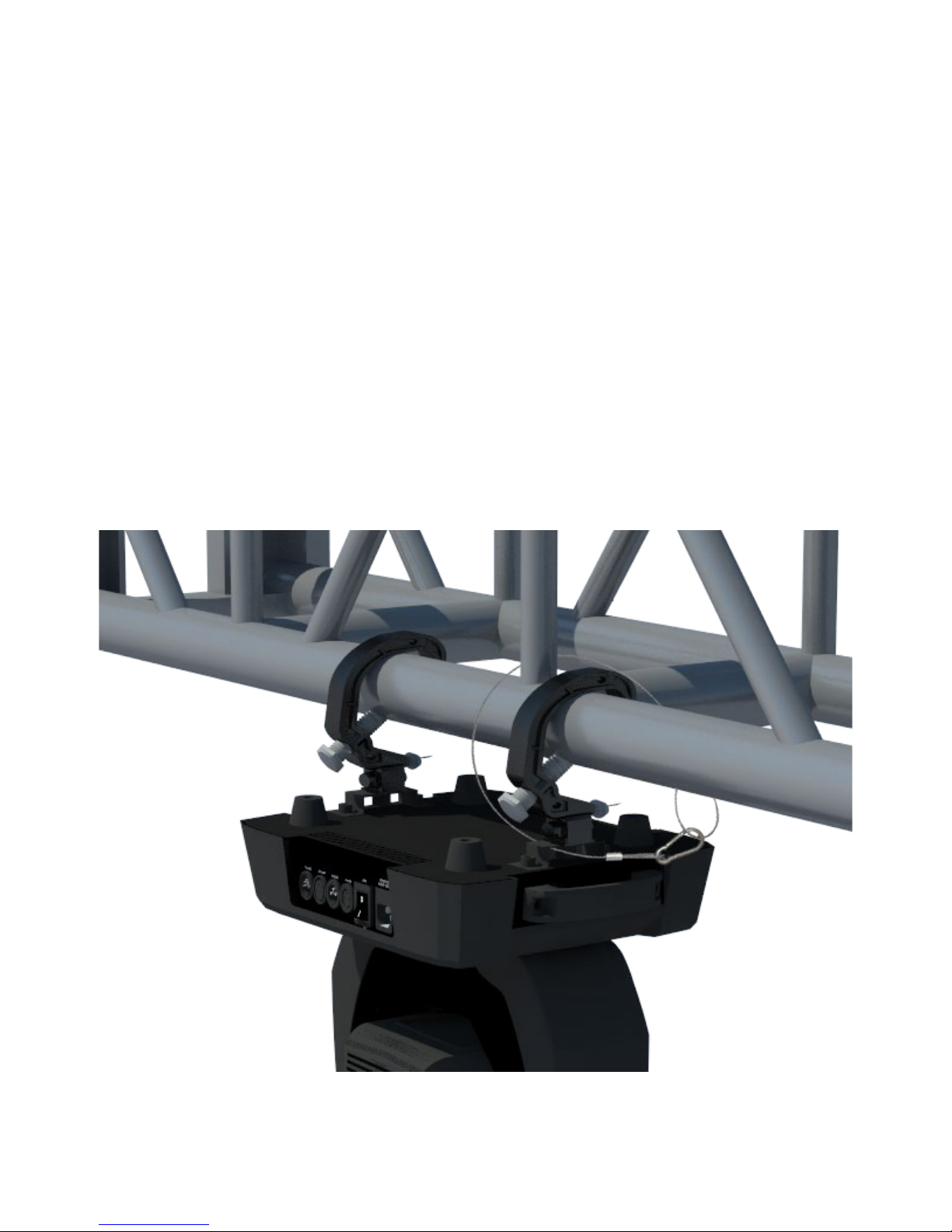
3. Working from a stable platform, hang the xture on the truss and fasten the
rigging clamps onto the truss.
4. Secure the xture with a safety cable as directed below.
5. Check that the head will not collide with other xtures or objects.
Securing with a safety cable
Secure the xture with a safety cable (or other secondary attachment) that is
approved for the weight of the xture so that the safety cable will hold the xture if
a primary attachment fails. Loop the safety cable through and around a secure metal
anchoring point.
Page 10

GLOW® Bumble Beam™ 10
AC Power
Warning! Read ‘Safety information’ on page 4 before
connecting the xture to AC mains power.
For protection from electric shock, the xture must be
grounded (earthed). The power distribution circuit must be
equipped with a fuse or circuit breaker and ground-fault
(earth-fault) protection.
Socket outlets or external power switches used to supply the xture with power must
be located near the xture and easily accessible so that the xtures can easily be
disconnected from power.
Do not insert or remove power cable to apply or cut power, as this may cause arcing
at the terminals that will damage the connectors.
Do not use an external dimming system to supply power to the xture, as this may
cause damage to the xture that is not covered by the product warranty.
The xture can be hard-wired to a building electrical installation if you want to install
it permanently, or a power plug (not supplied) that is suitable for the local power outlets can be installed on the power cable.
If you replace power plug on the power cable, install a grounding type (earthed) plug
with integral cable grip that is rated minimum 250 V, 5 A.
The xture has an auto-ranging power supply that accepts AC mains power at
100-240 V at 50/60 Hz. Do not apply AC mains power at any other voltage or frequency to the xture.
Page 11
GLOW® Bumble Beam™ 11
Fixture overview
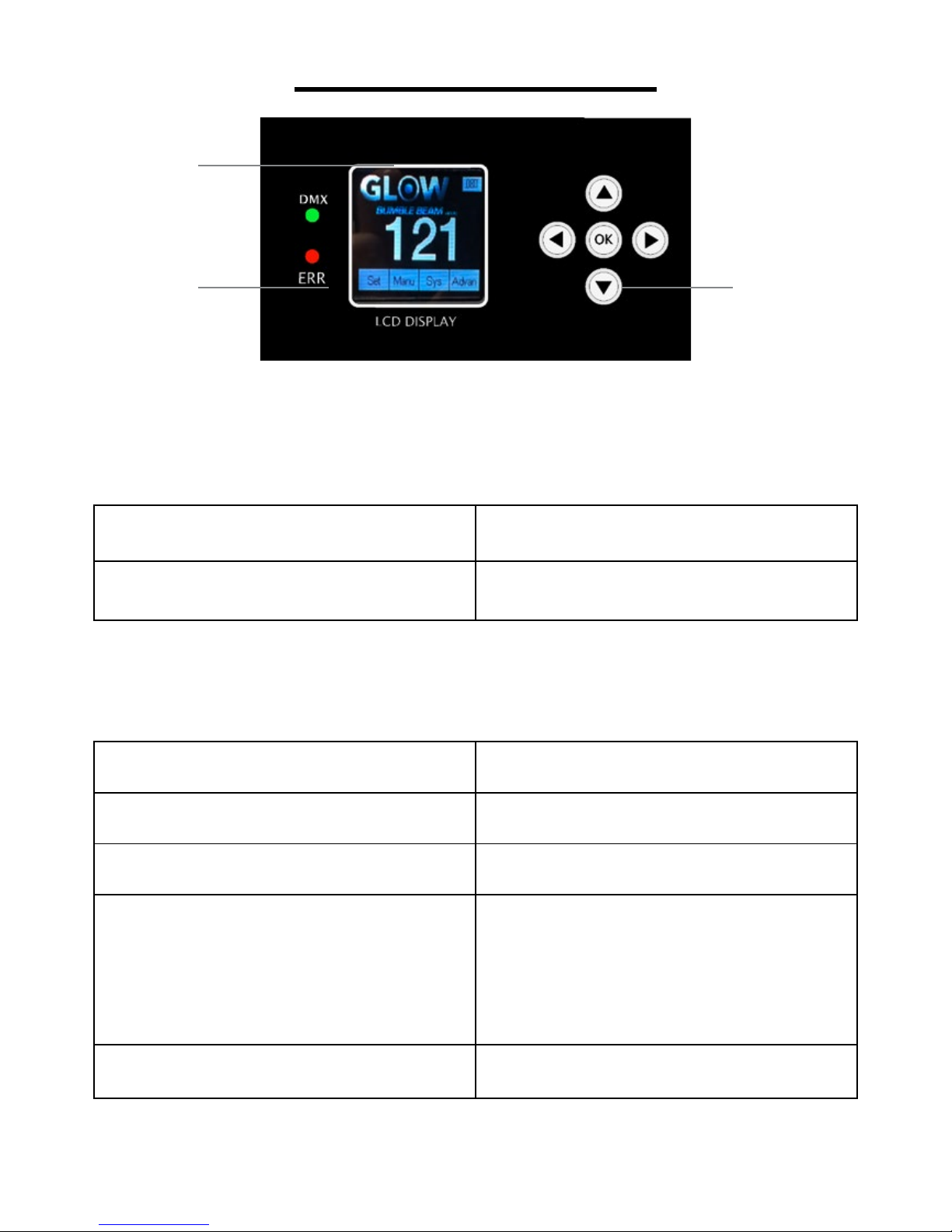
2
1 3
1 - LEDs
The LEDs on the front of the base give the following indications:
DMX Valid DMX signal present
ERR Error signal present
2 – Display
3 – Buttons
UP
Press UP for selection
DOWN
Press DOWN for selection
LEFT
Press LEFT for selection
RIGHT
• Activate the menu mode functions, or
• Return to the previous level of the
menu structure, or
• Hold to exit the menus
OK
Complete selected function
Page 12
GLOW® Bumble Beam™ 12
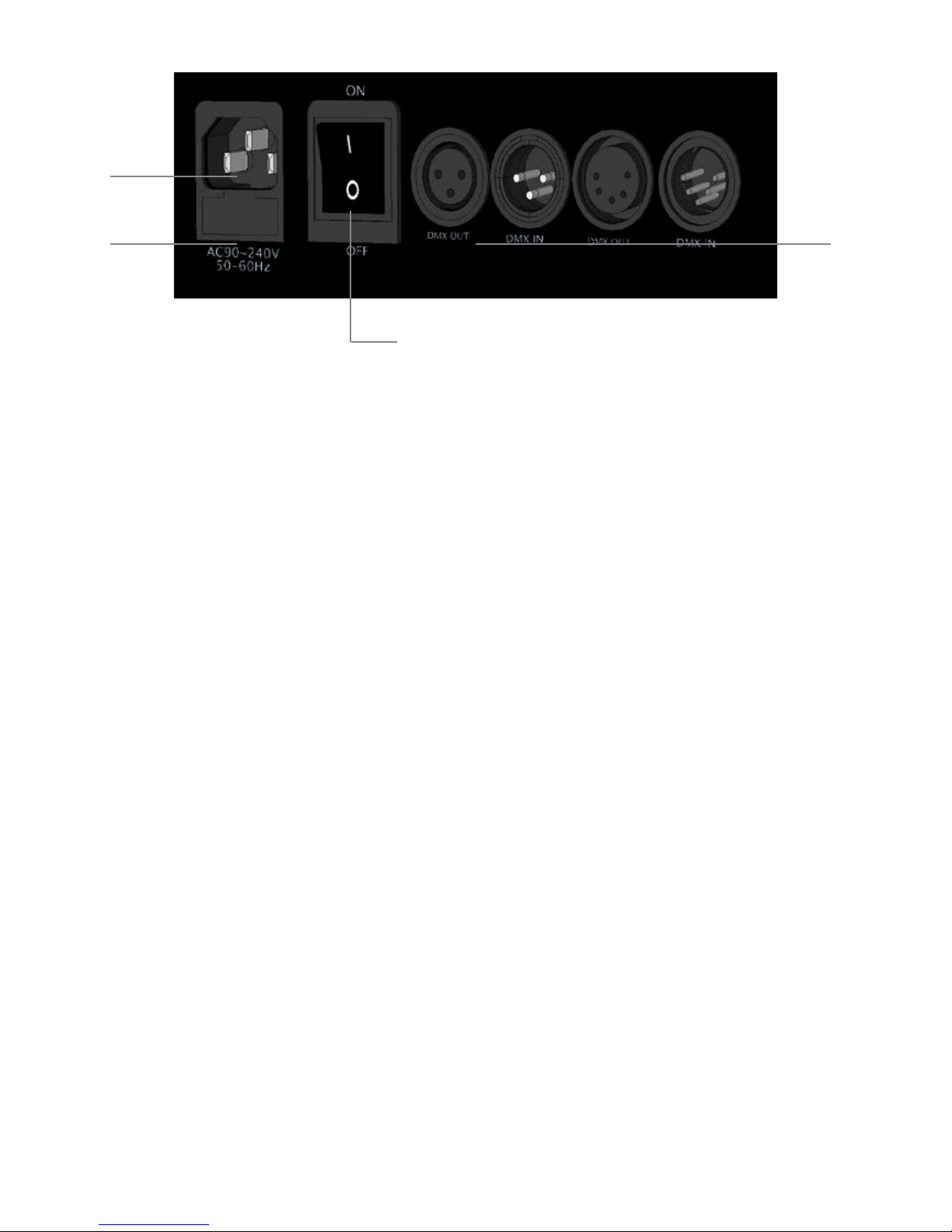
5
7 4
4 - DMX input/output 6
3 and 5-pin XLR sockets are provided for DMX input and output (throughput).
5 – AC mains power input
6 – Power on/off switch
7 – Fuse
The T5A xture fuse is located in a fuseholder below the power switch. An extra fuse
is attached to the fuse holder for quick replacement.
Control data link
A DMX 512 data link is required in order to control the xture via DMX. The xture
has 3-pin and 5-pin XLR connectors for DMX data input and output. The number
of daisy-chained xtures is limited by the number of DMX channels required by the
xtures in relation to the maximum 512 channels available in one DMX universe.
Note that if independent control of a xture is required, it must have its own DMX
channels. Fixtures that are required to behave identically can share the same DMX
address and channels. To add more xtures or groups of xtures when the above
limit is reached, add a DMX universe and another daisy-chained link.
Connecting the DMX data link
To connect the xture to data:
1. Connect the DMX data output from the controller to the rst xture’s male XLR
DMX input connector.
2. Connect the rst xture’s DMX output to the DMX input of the next xture
and continue connecting xtures output to input.
Page 13

GLOW® Bumble Beam™ 13
Fixture setup
This section explains the xture settings and utilities that the user has access to via
the control panel.
Settings are retained when the xture is powered off.
Using the control menus
To access the control menus, press the OK button. Navigate the menu
structure using the OK, LEFT and RIGHT buttons. Select any required
menu option using the OK button. To return to the previous level in the
menu structure without making a change, press the RIGHT button.
To exit the menus, press and hold the RIGHT button.
DMX function settings
DMX function settings include the DMX address and a DMX value viewer.
DMX addressing
The xture can be controlled using signals sent by a DMX controller. Each
DMX-controlled xture must have a DMX address set. If a xture has its DMX ad-
dress set to 1, for example( in 16 channels mode), then it uses channels 1 to 16.
The next xture on the DMX link can have its DMX address set to 17, the next to 33
and so on until the 512 channels in one DMX universe are
allocated.
For independent control, each xture must be assigned its own control channels.
Two xtures of the same type may share the same address, if identical behavior is
desired. Address sharing can be useful for diagnostic purposes and symmetric control, particularly when combined with the inverse pan and tilt options.
To set the xture’s DMX address:
1. In the control panel, select SET and press ENTER.
2. Use the UP and DOWN buttons to select DMX ADDRESS and press OK
to conrm. The present address will blink on the display.
3. Use the UP and DOWN buttons to select the address (1 to 512).
4. Once the address has been selected, press OK to set it (or press LEFT to exit
without making a change).
Page 14

GLOW® Bumble Beam™ 14
DMX viewer
You can check the DMX values that the xture is receiving on each DMX
channel in the VIEW DMX VALUE menu.
To see the DMX values:
1. Select DMX FUNCTIONS and press ENTER.
2. Use the UP and DOWN buttons to select VIEW DMX VALUE and press ENTER.
3. Use the UP and DOWN buttons to scroll through the DMX channels and press
ENTER to select a channel. The xture will display the DMX value it is receiving on
that channel.
4. Press MENU to exit the viewer.
Fixture settings
Pan and/or tilt inversion
The FIXTURE SETTINGS PAN INVERSE and TILT INVERSE menus can be
used to reverse the direction of pan and/or tilt. These settings are useful for
symmetrical effects with multiple xtures, or when coordinating the movement
of xtures that are oor mounted and rigged upside down.
To adjust the pan inversion settings:
1. Select FIXTURE SETTINGS and press ENTER to conrm.
2. Use the DOWN and UP buttons to select PAN INVERSE or TILT INVERSE and
press OK to conrm.
3. Use the DOWN and UP buttons to select the YES (inversion) or NO
(normal) mode.
4. Press OK to set (or press RIGHT to exit without making a change).
Page 15
GLOW® Bumble Beam™ 15
Lamp settings
Lamp on/off
To turn the lamp on or off via the control panel:
1. Select LAMP SETTINGS and press ENTER to conrm.
2. Use the DOWN and UP buttons to select ON/OFF and press OK to conrm.
3. Use the DOWN and UP buttons to select ON or OFF.
4. Press OK to conrm (or press RIGHT to exit without making a change).
State/power on
To set whether the xture should power the lamp on automatically when the
xture is powered on:
1. Select LAMP SETTINGS and press OK to conrm.
2. Use the DOWN and UP buttons to select STATE/POWER ON and press OK to
conrm.
3. Use the DOWN and UP buttons to select ON or OFF.
4. Press OK to conrm (or press RIGHT to exit without making a
change).
Display settings
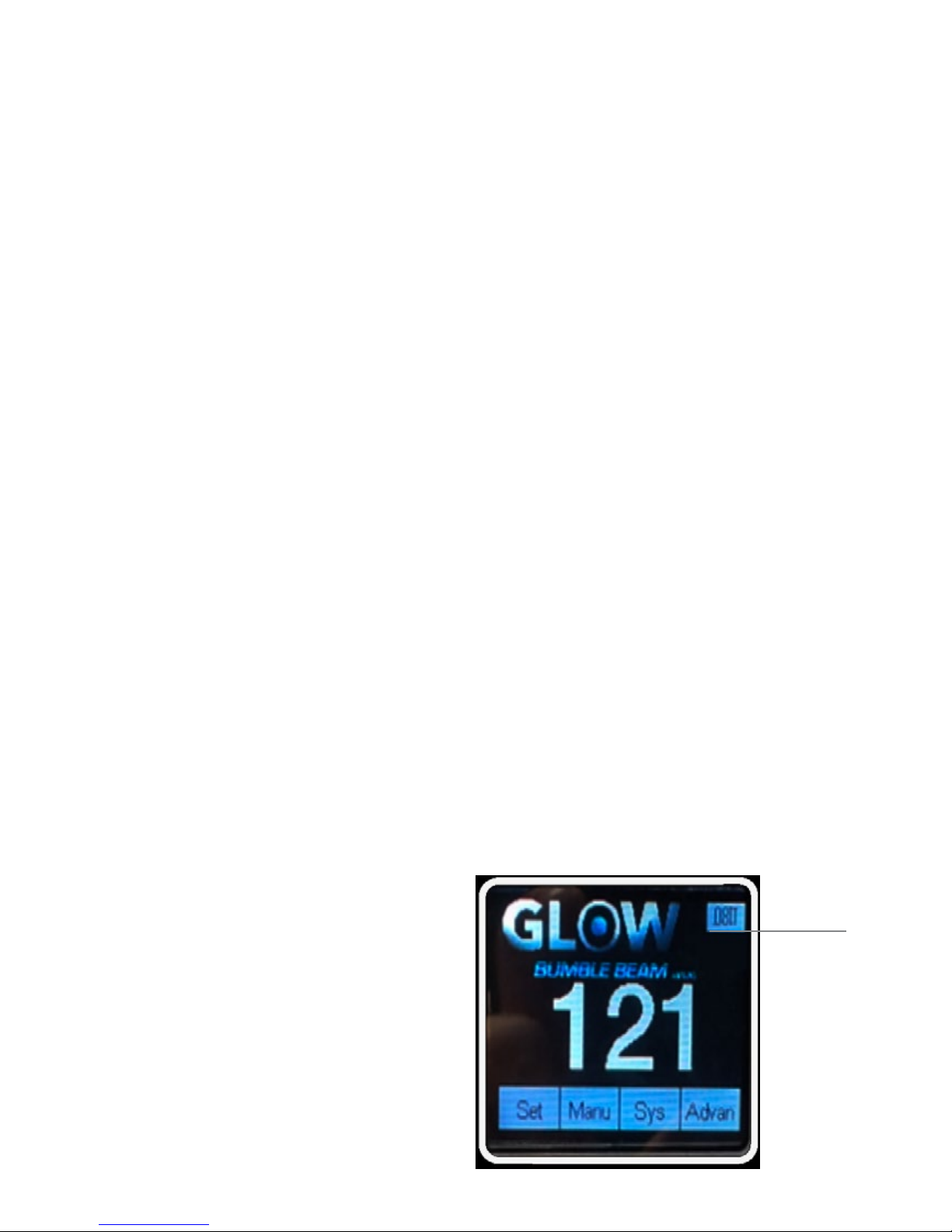
Invert display
INVERT
To invert the display:
1. Press LEFT then UP.
2. Press OK to conrm.
Page 16

GLOW® Bumble Beam™ 16
Manual settings
You can run an automatic test of all functions, or manually test individual
functions from the control menus.
Auto mode
To turn on an auto mode:
1. Select “SET” and press OK to conrm.
2. Use the UP and DOWN buttons to select MODE and press OK
to change the mode.
3. Use the UP and DOWN buttons to select auto mode and press OK
to conrm. The automatic mode will run.
Manual mode
Fixture functions can be tested or controlled without a DMX signal:
1. Select FIXTURE TEST and press ENTER to conrm.
2. Use the DOWN and UP buttons to select MANUAL TEST and press OK
to conrm.
3. Select and activate the functions you wish to control.
4. Press MENU to exit.
Fixture information
Fixture operating hours counter
To display the total number of hours the xture has been used:
1. Select FIXTURE INFORMATION and press ENTER to conrm.
2. Use the DOWN and UP buttons to select FIXTURE USE TIME and press OK to
conrm. The number of hours is shown in the display.
3. Press MENU to exit.
Page 17

GLOW® Bumble Beam™ 17
Lamp operating hours counter
The resettable lamp operating time counter lets you monitor lamp use and see
when lamp replacement is due. The counter is available in the FIXTURE
INFORMATION→LAMP ON TIME menu. Do not exceed the specied lamp
lifetime, or the lamp may explode. Reset the counter when you replace the lamp.
Firmware version
To display the software version installed in the xture:
1. Select FIXTURE INFORMATION and press OK to conrm.
2. Use the DOWN and UP buttons to select FIRMWARE VERSION and
press ENTER to conrm. The rmware version is shown in the display.
3. Press MENU to exit.
Reset functions or effects
The various effects—pan, tilt color, gobos, iris, focus, prism—or all effects, can
be manually reset to their home positions:
1. Select RESET FUNCTIONS and press OK to conrm.
2. Use the DOWN and UP buttons to select the function or effect that is to be
reset. Press OK.
3. Use the DOWN and UP buttons to select YES and
4. Press OK to conrm (or press RIGHT to exit without making a change).
Page 18

GLOW® Bumble Beam™ 18
Calibration
Calibration menu
You can callibrate any of pan, tilt, gobo, color, focus, dimmer, effect speed positions.
To adjust an effect home position offset:
1. Select “Advanced” then press OK button to enter the Advanced Settings.
2. Enter password: UP, DOWN, UP, DOWN
3. Select “Reset Callibration”, press OK to enter
4. Use UP and Down buttons to select parameter you want to callibrate then press
OK
5. Once the correct position has been reached, press ENTER to conrm (or press
RIGHT to exit without saving).
Page 19

GLOW® Bumble Beam™ 19
Effects
This section describes DMX-controllable effects that require particular
explanation. See DMX protocol on page 28 for a full list of the DMX channels
and values required to control the different effects.
Note that if a xture loses its DMX signal it will maintain its current effect until
powered off or reset.
Pan and tilt
The xture’s moving head can be panned through 540° and tilted through
270° using coarse or ne control channels. A range of pan/tilt
macros is available.
The xture incorporates pan and tilt feedback, so that if correct pan or tilt
position is lost, the shutter closes and the xture resets to the correct position.
This feature can be enabled or disabled as required (see ‘Control menus’ on page
27).
Function channel
The function DMX channel lets you adjust certain xture settings via DMX.
This can be useful if access to the xture’s control panel is difcult or
inconvenient when the xture is installed.
Dimming
Full range mechanical dimming is provided. Highly sensitive step motors ensure a
liniar transperant dimming curve.
Frost lter
The frost lter softens and diffuses the projection.
Strobe effects
A range of variable speed and random shutter/strobe effects are provided.
Page 20
GLOW® Bumble Beam™ 20
Gobos
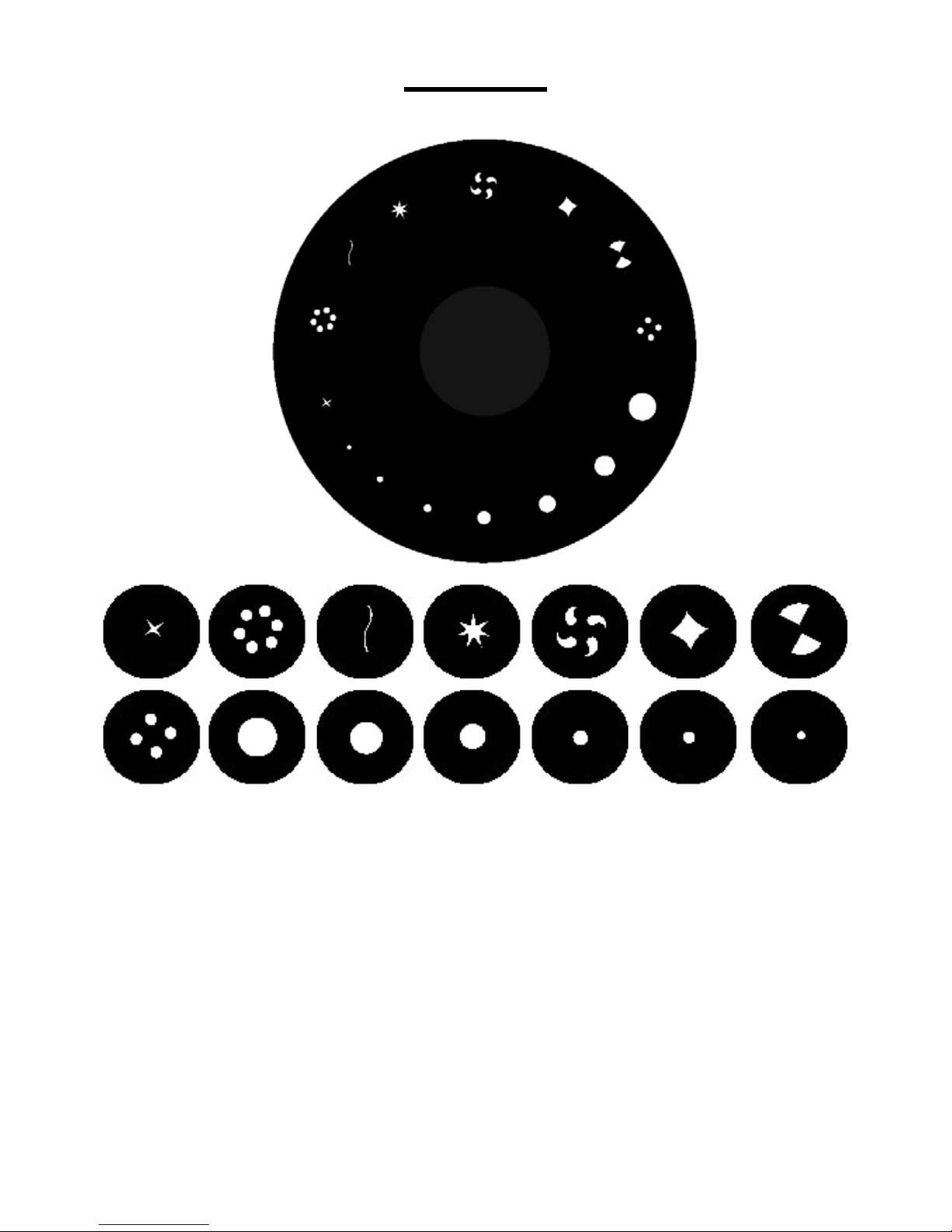
The xture contains a rotating wheel with 14 xed gobos:
Any gobo can be projected statically, or the wheel can be rotated clockwise or
counter-clockwise with variable speed, and index as well. The sharpness of gobo
projections can be adjusted via DMX using the focus channel.
Prism
The xture incorporates an 8-facet prism that can be inserted into the beam to
provide split beam effects. The prism can be set to an indexed position or
rotated clockwise or counter-clockwise. A range of prism macros and movement
effects are provided.
Page 21
GLOW® Bumble Beam™ 21
Features
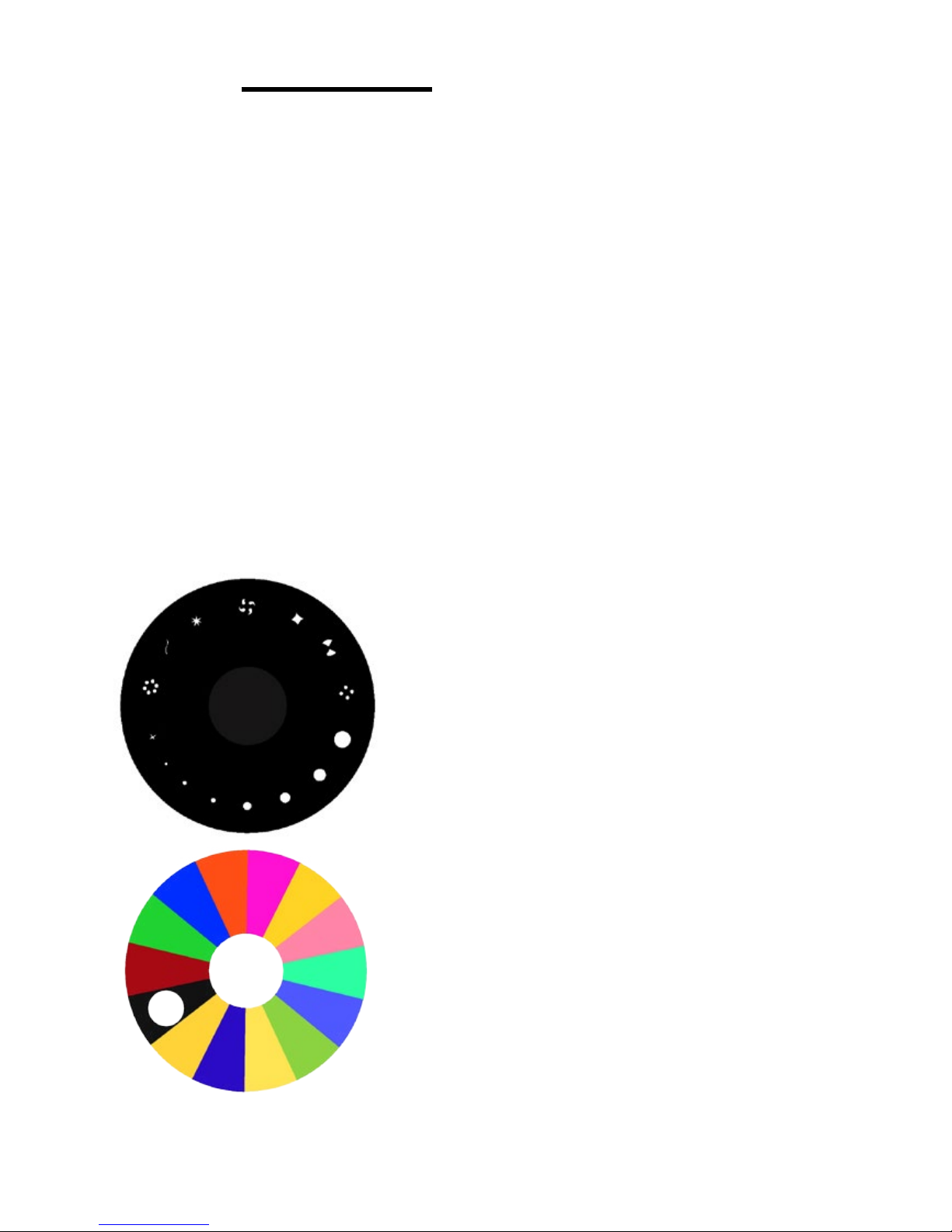
• Bright, punchy beam with 78,700 lux @ 15 m using
132W HRI lamp
• 17 gobos with continuous variable wheel scroll
• 8-facet Prism, independently
controllable for amazing gobo effects
• Color wheel with 14 colors, split color ability, and
continuous variable-speed scrolling
• 3- and 5-pin DMX input/output connections
• Simple and complex DMX channel proles for
programming versatility
Page 22

GLOW® Bumble Beam™ 22
Warning! Read ‘Safety information’ on page 4 before
servicing the xture.
Refer any service operation not described in this user manual to a
qualied service technician.
Disconnect the xture from mains power and allow to cool completely before
cleaning or servicing.
Service xtures in an area where there is no risk of injury from failing parts,
tools or other materials.
Excessive dust, smoke uid, and particle buildup degrades performance,
causes overheating and will damage the xture. Damage caused by inadequate
cleaning or maintenance is not covered by the product warranty.
Cleaning
The cleaning of external optical lenses must be carried out periodically to
optimize light output. Cleaning schedules for lighting xtures vary greatly
depending on the operating environment. It is therefore impossible to specify
precise cleaning intervals for the xture. Environmental factors that may result
in a need for frequent cleaning include:
• Use of smoke or fog machines.
• High airow rates (near air conditioning vents, for example).
• Presence of cigarette smoke.
• Airborne dust (from stage effects, building structures and ttings or the natural
environment at outdoor events, for example).
If one or more of these factors is present, inspect xtures within their rst 100 hours
of operation to see whether cleaning is necessary. Check again at frequent intervals.
This procedure will allow you to assess cleaning requirements in your particular
situation.
Use gentle pressure only when cleaning, and work in a clean, well-lit area. Do
not
use any product that contains solvents or abrasives, as these can cause surface
damage.
Maintenance
Page 23

GLOW® Bumble Beam™ 23
To clean the xture:
1. Disconnect the xture from power and allow it to cool for at least 10 minutes.
2. Vacuum or gently blow away dust and loose particles from the outside of
the xture and the air vents at the back and sides of the head and in the base
with low-pressure compressed air
3. Clean lenses by wiping gently with a soft, clean lint-free cloth moistened with a
weak detergent solution. Do not rub the surface hard: lift particles off with a soft
repeated press. Dry with a soft, clean, lint-free cloth or low pressure compressed
air. Remove stuck particles with an unscented tissue or cotton swab moistened with
glass cleaner or distilled water.
4. Check that the xture is dry before reapplying power.
Page 24

GLOW® Bumble Beam™ 24
Lamp replacement
Warning! Wear safety glasses and gloves when handling
lamps.
To avoid the risk of a discharge lamp exploding in the xture, replace
the lamp when it reaches its expected lifetime.
Install only lamps that are approved by GLOW® Professional for this x
ture.
The lamp must be perfectly clean and totally free of oil and grease.
Never touch the lamp with bare hands.
If you contaminate the lamp, clean it with an alcohol wipe and then
dry it with a lint-free cloth.
For best results the lamp can be adjusted to obtain the best projection.
Please follow the instructions below to replace the lamp:
1. Disconnect the xture from power and allow it to cool for two hours.
2. Remove the xture head covers using a Phillips screwdriver.
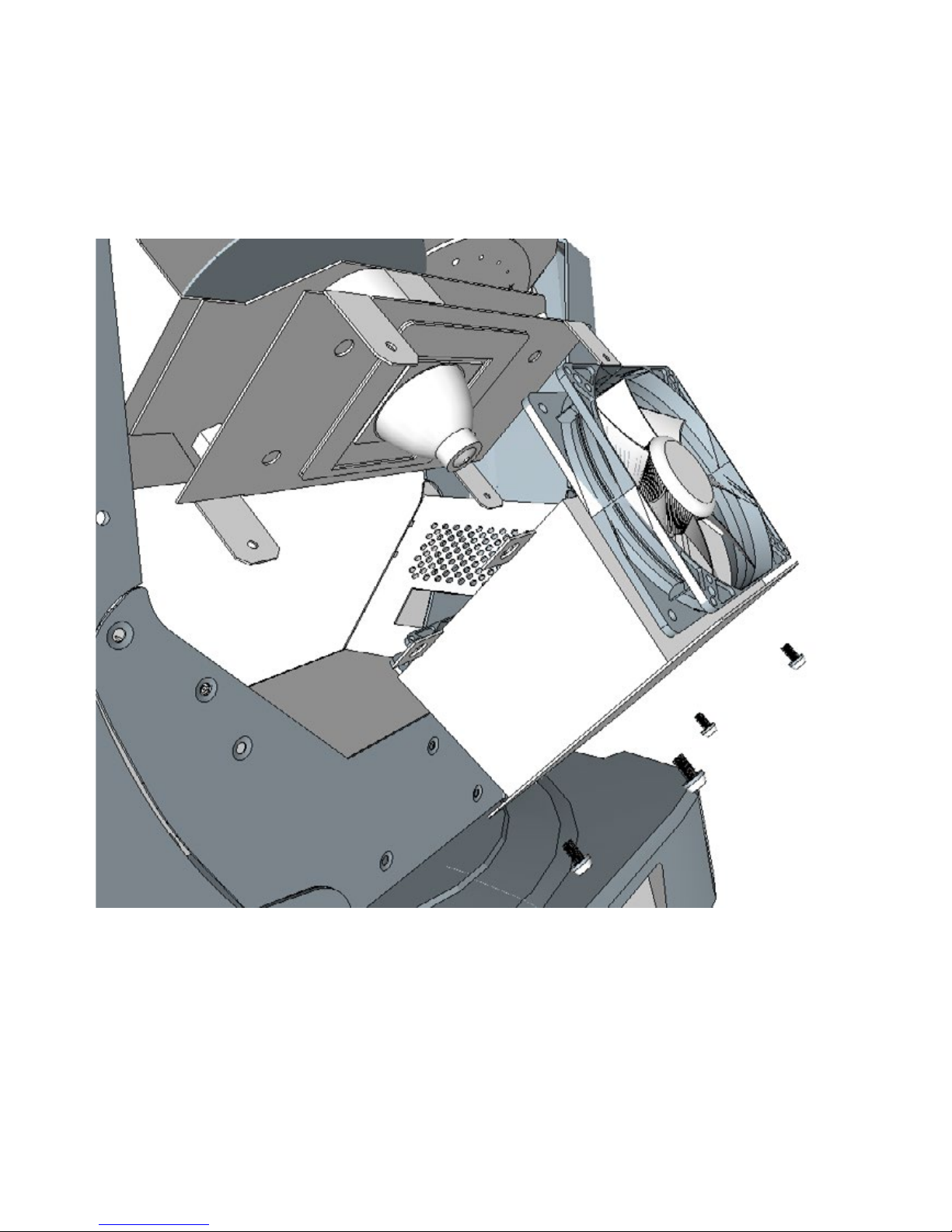
3. Position the head as shown below and remove the lamp cooling fan
at the rear of the head
4. Lift the lamp out of its recess.
5. Disconnect the lamp and connect the replacement lamp. Only use
only a lamp that is approved by GLOW® Professional.
6. Place the new lamp into the lamp recess.
7. See illustration below. Adjust the lamp using a slotted (at head)
screwdriver until it is centralized.
8. Reinstall the fan and secure i
t.
Page 25
GLOW® Bumble Beam™ 25
9. Replace and secure the head covers before reapplying power.
10. Reset the lamp hour counter using the control panel.
Page 26

GLOW® Bumble Beam™ 26
Replacing the primary fuse
If the xture is completely dead, the xture’s primary fuse T5 may have blown
and it may be necessary to install a new fuse. This fuse is located in a fuseholder
next to the power ON/OFF switch on the connections panel. See ‘Fixture overview’
on page 12.
If you need to replace a fuse:
Disconnect the xture from power and allow it to cool for at least 10 minutes.
1. Pull the cap of the fuseholder and remove the fuse. Replace with a fuse of the
same size and rating only.
2. Reinstall the fuseholder cap before reapplying power.
Other service and repairs
There are no user-serviceable parts inside the xture. Do not open the housing. Never try to repair the xture yourself, as this may result in damage or malfunc-
tion, and it may void your product warranty. Service operations not described in this
manual may only be carried out by an authorized GLOW® Professional Bumble
Beam™ service agent.
Installation, on-site service and maintenance can be provided worldwide by
the GLOW® Professional and its approved agents, giving owners access to
GLOW® Professional expertise and product knowledge in a partnership that will
ensure the highest level of performance throughout the product’s lifetime. Please
contact your GLOW® Professional Bumble Beam™ supplier for details.
Page 27
GLOW® Bumble Beam™ 27
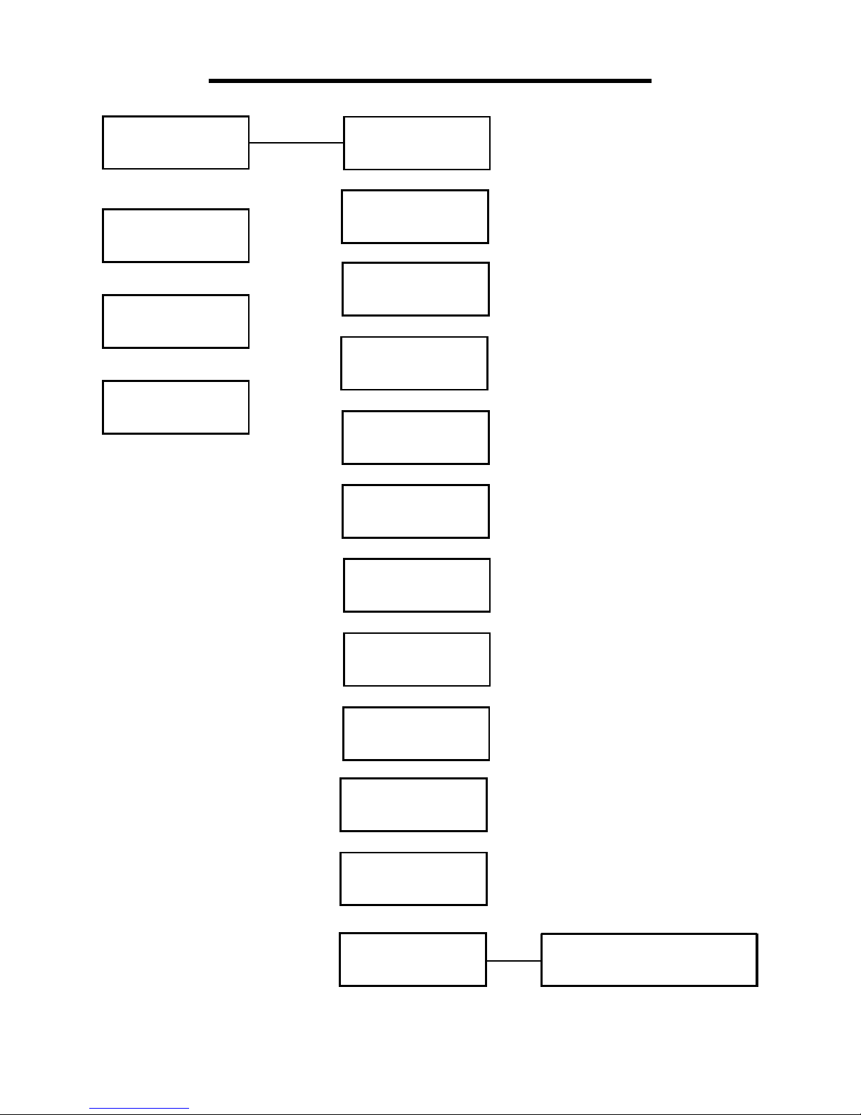
Set
Manu
Sys
Advan
Run Mode
DMX address
Channel Mode
Invert Pan
Invert Tilt
Pan-Tilt Swap
Pan-Tilt Encoder
No DMX Signal
Display
Lamp on
@Startup
Linear Color
Load Default
Sure to Load Default
Display Menu Settings
Page 28
GLOW® Bumble Beam™ 28
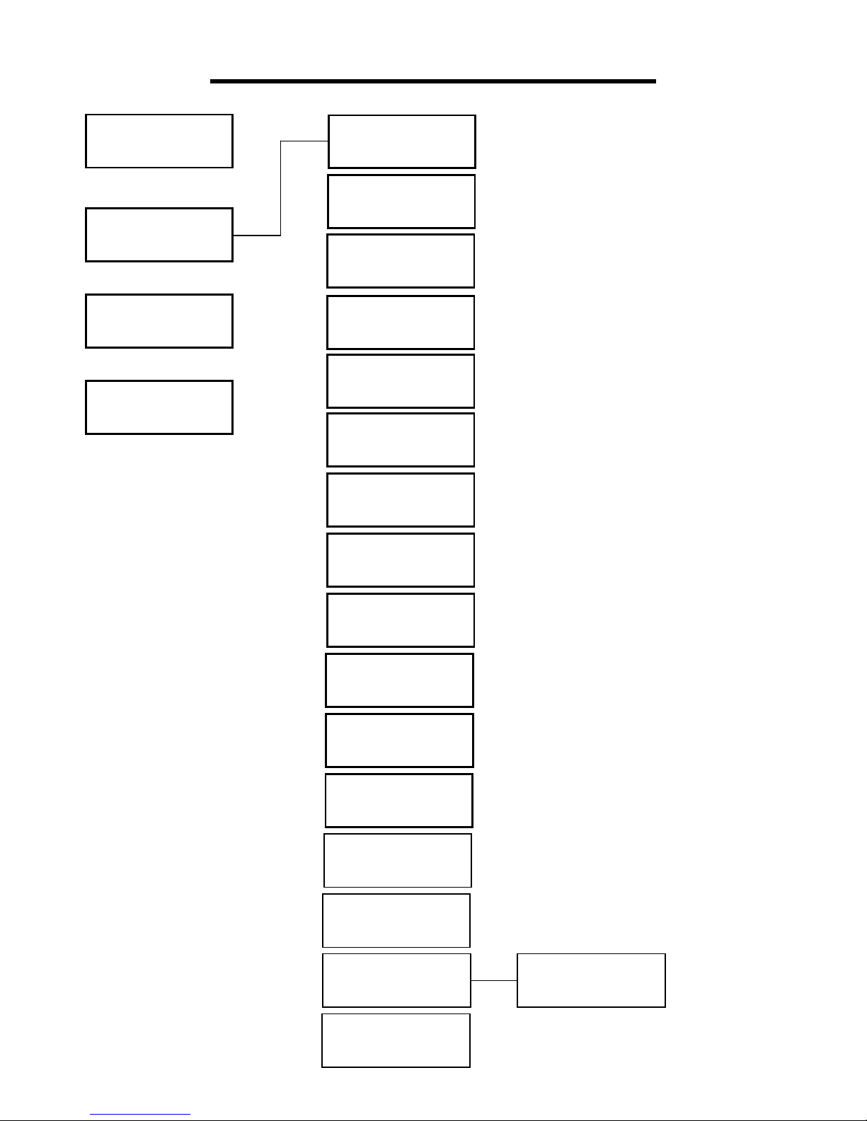
Set
Manu
Sys
Advan
Color
Shutter/Strobe
Dimmer
Gobo
Prism
Prism Rotation
Macro Function
Frost
Focus
Pan
Pan Fine
Tilt
Tilt Fine
Pan-Tilt Speed
Reset
Lamp Power
Sure to Reset?
Display Menu Settings
Page 29
GLOW® Bumble Beam™ 29
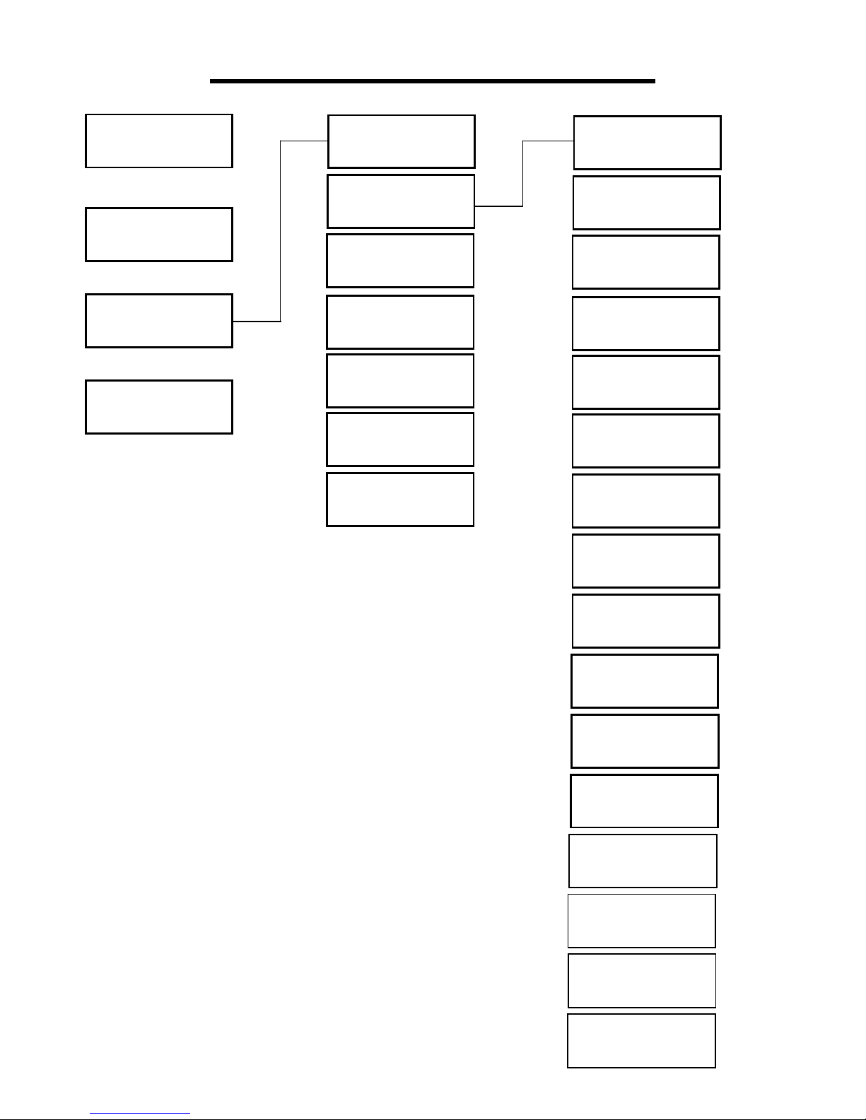
Set
Manu
Sys
Advan
Firmware
DMX Monitor
System Errors
Total Fixture
Hours
Partial Fixture
Hours
Total Lamp
Hours
Partial Lamp
Hours
Display Menu Settings
Color
Shutter/Strobe
Dimmer
Gobo
Prism
Prism Rotation
Macro Function
Frost
Focus
Pan
Pan Fine
Tilt
Tilt Fine
Pan-Tilt Speed
Reset
Lamp Power
Page 30
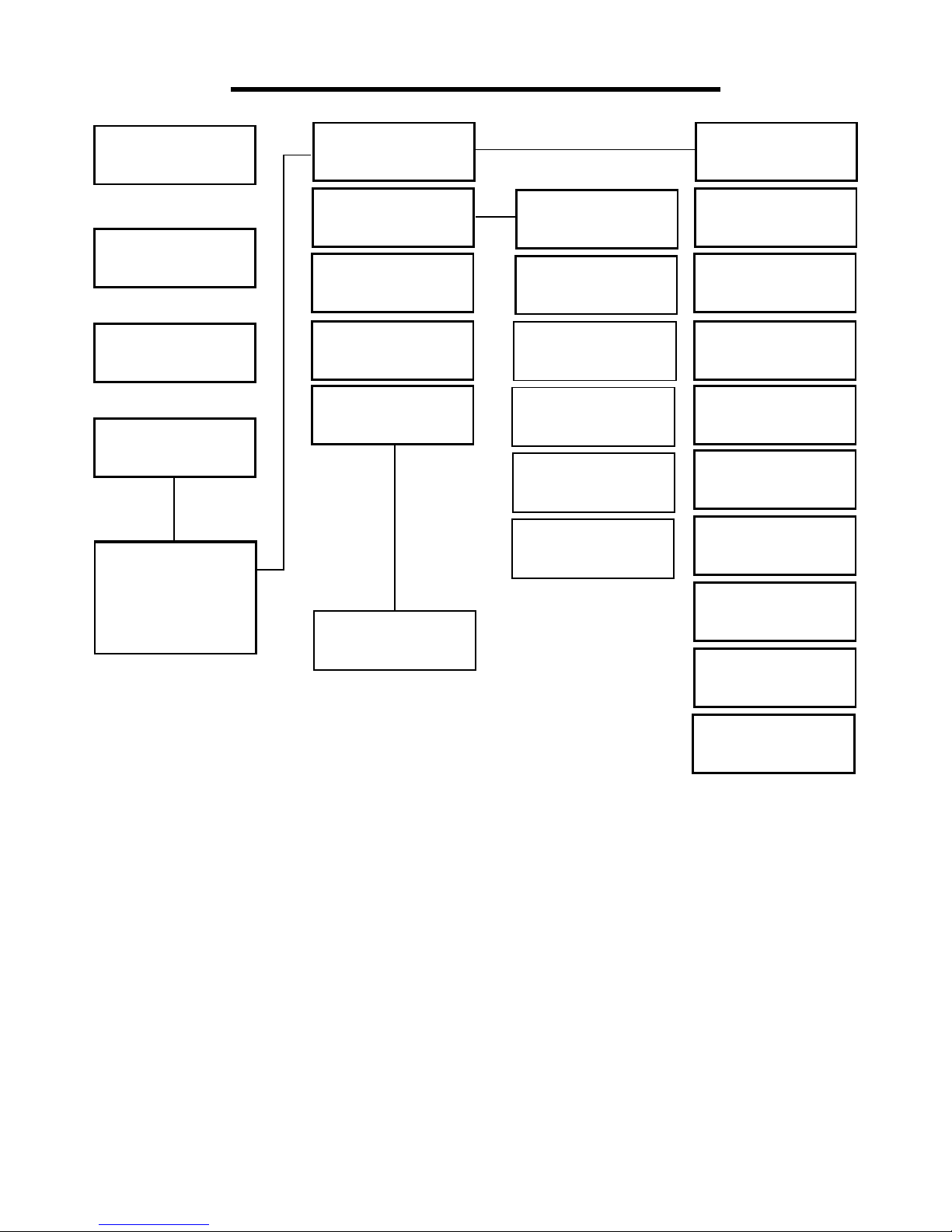
GLOW® Bumble Beam™ 30
Set
Manu
Sys
Advan
Sensor Monitor
Reset Calibration
Zero Point
Calibration
Lamp Life
Hours
Lamp Hours
Clear
Display Menu Settings
Pan Hall State
Tilt Hall State
Color Hall State
Gobo Hall State
Focus Hall State
Prism/Focus
Hall State
Pan Codewheel
State
Tilt Codewheel
State
Pan Codewheel
Step
Tilt Codewheel
Step
Pan Calibration
Tilt Calibration
Color Calibration
Gobo Calibration
Focus Calibration
Dimmer Calibra-
tion
Please input
password:
UP, DOWN
UP, DOWN, OK
Sure to Lamp
Hours Clear?
Page 31

GLOW® Bumble Beam™ 31
DMX CHART
DMX PROTOCOL
Channel 16 Channel mode 20 Channel mode
1 COLOR WHEEL COLOR WHEEL
2 STROBE STROBE
3 SHUTTER SHUTTER
4 GOBO GOBO
5 PRISM PRISM
6 PRISM ROTATION PRISM ROTATION
7 MACRO MACRO
8 FROST FROST
9 FOCUS FOCUS
10 PAN PAN
11 PAN FINE PAN FINE
12 TILT TILT
13 TILT FINE TILT FINE
14 PAN / TILT TIME PAN / TILT TIME
15 RESET RESET
16 LAMP CONTROL LAMP CONTROL
17 RFU
18 COLOR TIME
19 DIMMER PRISM FROST
TIME
20 GOBO TIME
Page 32

GLOW® Bumble Beam™ 32
COLOR WHEEL (channel 1)
DMX VALUE Function
0 White
5 White + Red
10 Red
15 Red + Green
20 Green
25 Green + Blue
30 Blue
35 Blue + Orange
40 Orange
45 Orange + Pink
50 Magenta
55 Magenta + Yellow
60 Yellow
65 Yellow + Lavender
70 Lavender
75 Lavender + Cyan
80 Cyan
85 Cyan + Ice
90 Ice
95 Ice + Light Green
100 Light Green
105 Light Green+ CTO 260
110 CTO 260
115 CTO 260 + Magenta
120 Magenta
125 Magenta + CTB 8000
130 CTB 8000
135 CTB 8000 + White
140-255 Slow Rotation - Fast Rotation
Page 33
GLOW® Bumble Beam™ 33
STROBE (channel 2)
Value Function
0 - 3 Closed
4 - 207 Slow - Fast Strobe
208 - 212 Open
213 - 225 Random Slow Strobe
226 - 238 Random Medium Strobe
239 - 251 Random Fast Strobe
252 - 255 Open
DIMMER (channel 3)
Value Function
0 - 255 0% - 100%
Page 34
GLOW® Bumble Beam™ 34
GOBO (channel 4)
Value Function
0 OPEN
5 GOBO 1
10 GOBO 2
15 GOBO 3
20 GOBO 4
25 GOBO 5
30 GOBO 6
35 GOBO 7
40 GOBO 8
45 GOBO 9
50 GOBO 10
55 GOBO 11
60 GOBO 12
65 GOBO 13
70 GOBO 14
75 - 129 FAST - SLOW ROTATION
130 - 134 STOP
135 - 185 SLOW - FAST ROTATION
186 - 190 GOBO 1 SHAKE FAST - SLOW
191 - 195 GOBO 2 SHAKE FAST - SLOW
.................. GOBO 3 TO GOBO 13
246 - 250 GOBO 13 SHAKE FAST - SLOW
251 - 255 GOBO 14 SHAKE FAST - SLOW
PRISM (channel 5)
Value Function
0 - 127 PRISM OFF
128 - 255 PRISM ON
PRISM ROTATION (channel 6)
Value Function
0 - 63 POSITION
64 - 127 SLOW - FAST ROTATION
128 - 191 FAST - SLOW ROTATION
192 - 255 SLOW - FAST ROTATION
Page 35
GLOW® Bumble Beam™ 35
Macro Function (channel 7)
0 - 10 Open White
11 - 80 Color Wheel
81 - 130 Gobo Wheel + Prism rotate left
131 - 155 Shake
156 - 180 Gobo Wheel + Prism rotate right
181 - 185 Gobo Wheel
186 - 190 Shake
191 - 195 Strobe Slow
196 - 200 Shake
201 -205 Color Wheel
206 - 245 Gobo Wheel + Prism Rotate
246 - 250 Strobe
251 - 255 Gobo + Prism Rotate
FROST (channel 8)
Value Function
0 - 127 FROST OFF
128 - 255 FROST ON
FOCUS (channel 9)
Value Function
0 - 255 0% - 100%
PAN / TILT SPEED (channel 14)
Value Function
0 - 255 FAST - SLOW SPEED
Page 36
GLOW® Bumble Beam™ 36
RESET (channel 15)
Value Function
0 - 25 UNUSED RANGE
26 - 76 EFFECTS RESET
77 - 127 PAN / TILT RESET
128 - 255 COMPLETE RESET
LAMP CONTROL (channel 16)
Value Function
0 - 9 UNUSED RANGE
10 - 100 LAMP OFF
101 - 255 LAMP ON
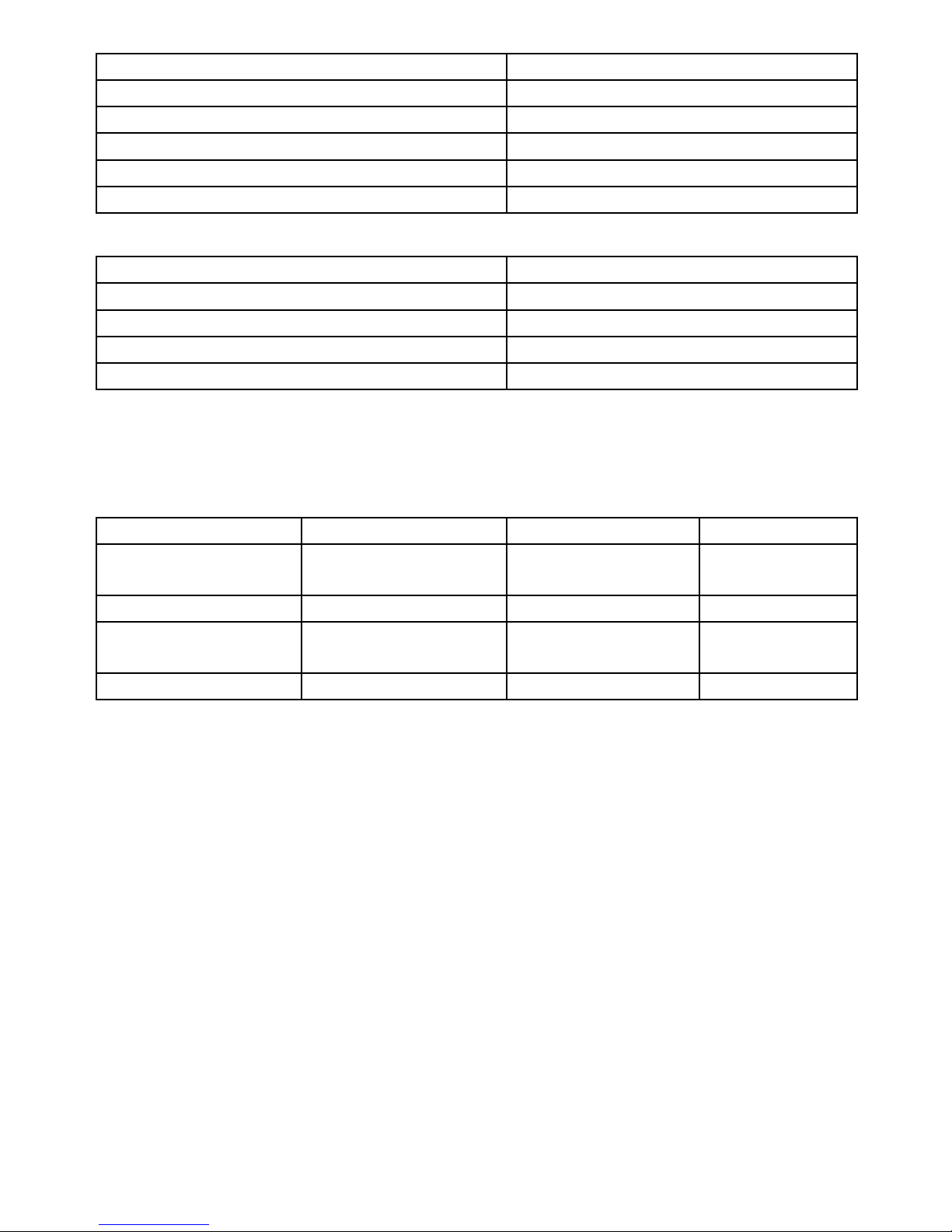
TIMING CHANNELS
TIMING CHANNEL FUNCTION REMARK
17 RFU UNUSED 0 - 255 FAST -
SLOW SPEED
18 COLOR TIME COLOR WHEEL
19 BEAM TIME DIMMER - PRISM -
FROST
20 GOBO TIME STATIC GOBO
Page 37
GLOW® Bumble Beam™ 37
Bumble Beam Specifications
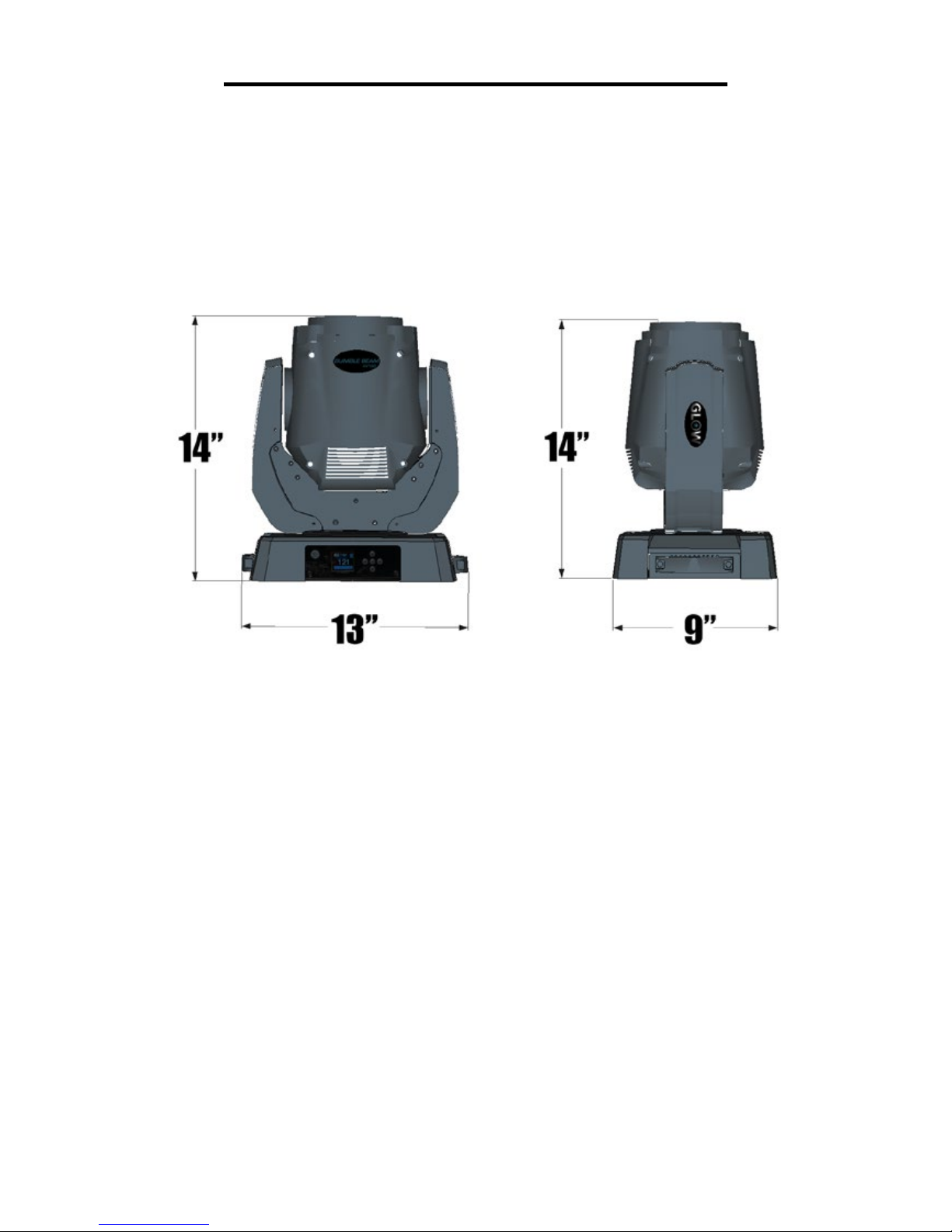
Physical
Length: ................................................................................................330 mm (13 in.)
Width: ..................................................................................................229 mm (9 in.)
Height: .................................................................................................356 mm (14 in.)
Weight: .................................................................................................7 kg (15.4 lbs.)
Lamp
Approved lamp: .................................................................. HRI 132W 2R Lamp
Color temperature: .......................................................................................... 8000 K
CRI (Color rendering index): ................................................................................... 75
Average lifetime: ....................................................................................... 2000 hours
Dynamic Effects
Color wheel: ............ 14 colors plus open, rotation with variable direction and speed
Static gobo wheel: ............................ 17 gobos plus open, wheel rotation and shake
Pre-programmed effects: .......................... 31 pan and tilt macros, adjustable speed
Shutter: ................................ Strobe effect, pulse effects, instant open and blackout
Prism: .......................................... 8-facet, rotation and index with variable direction
and speed
Frost: ........................................................................................................ Fade in/out
Focus: ......................................................................................................... Motorized
Dimmer: ......................................................... 0 - 100%, four dimming curve options
Pan: .................................... 540°, with coarse & ne control and speed, P/T macros
Tilt: ...................................... 270°, with coarse & ne control and speed, P/T macros
Page 38

GLOW® Bumble Beam™ 38
Optics
Beam angle: ................................................................................................... 1.8°
Control and Programming
Control system: .................................................................................................. DMX
DMX channels: .................................................................................................. 16,20
Setting and addressing: ........................................................... USITT DMX512/1990
Pan and tilt speed: .......................... Adjustable via onboard control panel and DMX
Head position: ............................................................... Pan/tilt feedback correction
Construction
Color: ................................................................................................................ Black
IP rating: ............................................................................................................ IP 20
Installation
Minimum distance from illuminated surfaces: ...................................... 12 m (39.4 ft.)
Location: ........................... Indoor use only, must be fastened to surface or structure
Mounting points: ............................................. Two 3/8” nut bases for rigging clamps
Orientation: .......................................................................................................... Any
.
Connections
AC power input: ............................................................................ EURO Cable
DMX data in/out: ............................................................... 3-pin & 5-pin locking XLR
Electrical
AC power: ................................................................................... 100-240 V, 50/60Hz
Fuse: .................................................................................................................... T5A
Power supply unit: .......................................... Auto-ranging electronic switch mode
Typical power and current
110 V, 60 Hz: .......................................................................... 1.5 A, 160 W,
230 V, 50 Hz: .......................................................................... 0.7 A, 154 W
Measurements made at nominal voltage. Allow for a deviation of +/- 10%.
Page 39

GLOW® Bumble Beam™ 39
Thermal
Cooling: ..................................................................................................... Forced air
Maximum ambient temperature (Ta max.): .......................................... 40° C (104° F)
Minimum ambient temperature (Ta min): ............................................ .-25°C (-13° F)
Total heat dissipation (calculated, +/- 10%): ......................................... 1200 BTU/hr.
Included Items
3 ft Power cable, User Manual
Specications are subject to change without notice.
For latest product specications, see www.Glow-Lighting.com
 Loading...