

Page 1

ANTENNE TV SATELLITARI MARINE E PER IMBARCAZIONI FLUVIALI
SERIE MK2+
1
SATELLITE TV ANTENNAS FOR MARINE AND
SERIES MK2+
ANTENNES TV SATELLITAIRES POUR BATEAUX MARITIMES
ET FLUVIAUX SÉRIE MK2+
SATELLITEN-TV-ANTENNEN FÜR MEER- UND FLUSSBOOTE
SERIE MK2+
ANTENAS DE TV SATELITAL PARA EMBARCACIONES MARÍTIMAS Y
FLUVIALES SERIE MK2+ 169
RIVER BOATS
43
85
127
Page 2

Page 3
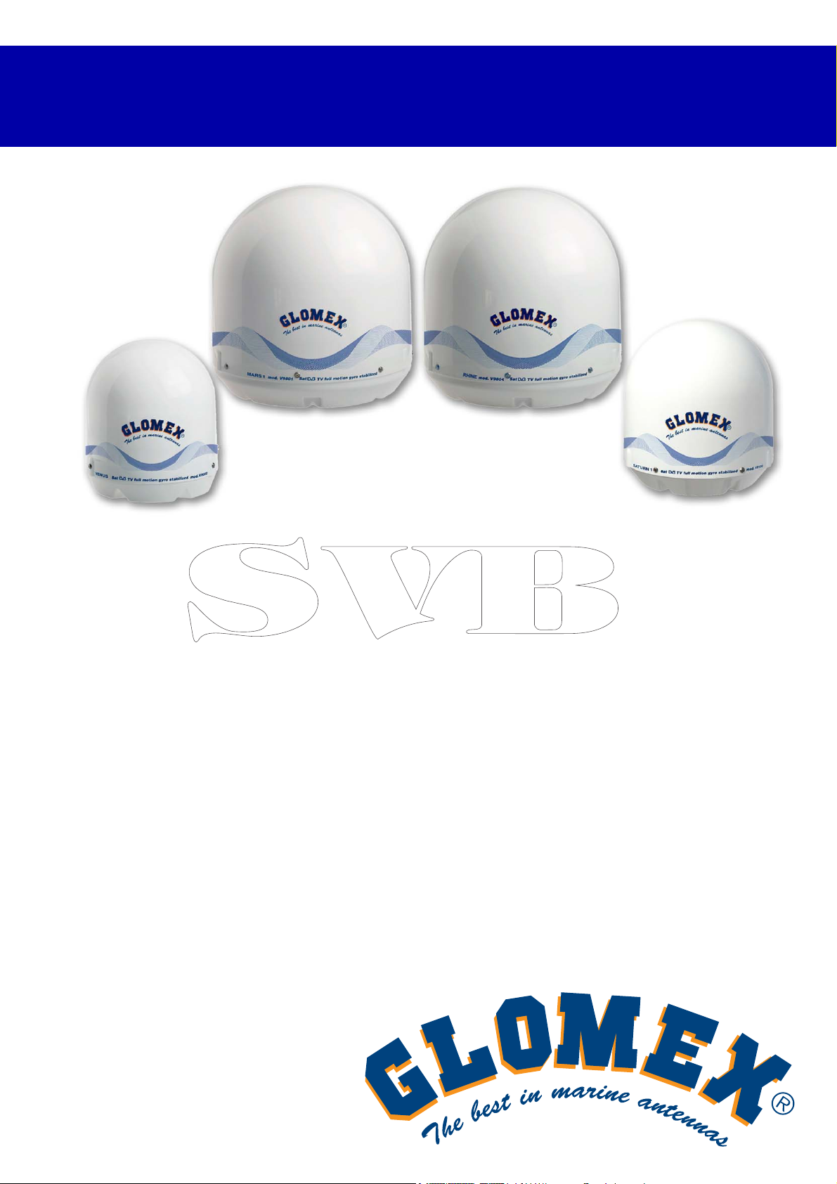
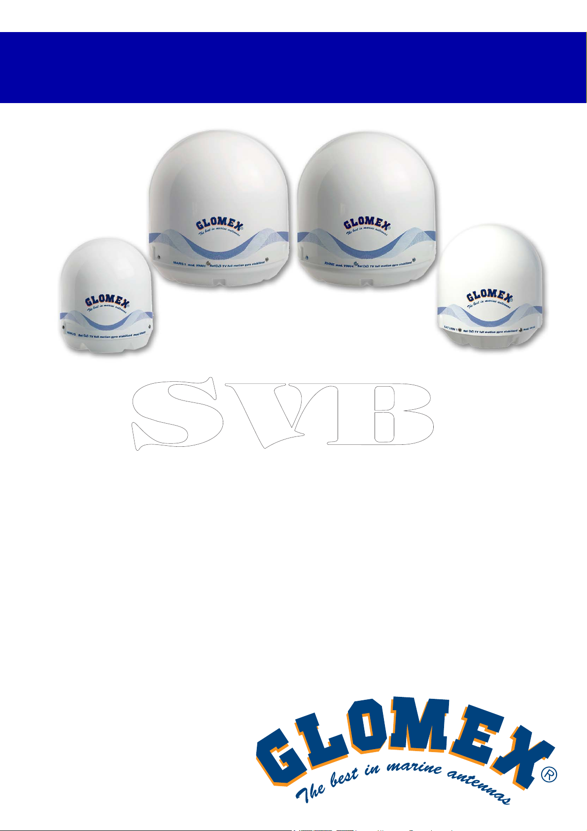
VENUS V9000
SATURN V9100 V9104 V9104SKEW
MARS V9801 V9804 V9804SKEW
RHINE R9804
ANTENNE TV SATELLITARI
MARINE E PER IMBARCAZIONI
FLUVIALI
SERIE MK2+
MANUALE D’INSTALLAZIONE E D’USO
Page 4
VENUS SATURN MARS RHINE
ITALIANO
2
www.glomex.it
Page 5
VENUS SATURN MARS RHINE
INDICE
1. INTRODUZIONE . . . . . . . . . . . . . . . . . . . . . . . . . . . . . . . . . . . . . . . . . . . . . . . . . . . . . . . . . 5
1.1 LETTERA DI CONSEGNA . . . . . . . . . . . . . . . . . . . . . . . . . . . . . . . . . . . . . . . . . . . . . . . . 5
1.2 IDENTIFICAZIONE ANTENNA . . . . . . . . . . . . . . . . . . . . . . . . . . . . . . . . . . . . . . . . . . . . 5
1.3 GARANZIA . . . . . . . . . . . . . . . . . . . . . . . . . . . . . . . . . . . . . . . . . . . . . . . . . . . . . . . . . . . . 5
1.4 NORME DI SICUREZZA GENERALI . . . . . . . . . . . . . . . . . . . . . . . . . . . . . . . . . . . . . . . . 6
1.5 AMBIENTE . . . . . . . . . . . . . . . . . . . . . . . . . . . . . . . . . . . . . . . . . . . . . . . . . . . . . . . . . . . . 6
2. DESCRIZIONE PRODOTTO . . . . . . . . . . . . . . . . . . . . . . . . . . . . . . . . . . . . . . . . . . . . . . . . 7
2.1 VENUS V9000 - SATURN V9100 - MARS V9801 . . . . . . . . . . . . . . . . . . . . . . . . . . . . . . 7
2.2 SATURN V9104 - V9104SKEW - MARS V9804 - V9804SKEW . . . . . . . . . . . . . . . . . . . 7
2.3 RHINE R9804. . . . . . . . . . . . . . . . . . . . . . . . . . . . . . . . . . . . . . . . . . . . . . . . . . . . . . . . . . 7
3. CONTENUTI . . . . . . . . . . . . . . . . . . . . . . . . . . . . . . . . . . . . . . . . . . . . . . . . . . . . . . . . . . . . 8
3.1 ACCESSORI OPZIONALI (NON INCLUSI) PER L’UTILIZZO
DELLE ANTENNE GLOMEX . . . . . . . . . . . . . . . . . . . . . . . . . . . . . . . . . . . . . . . . . . . . . 12
4. ATTREZZI NECESSARI PER IL MONTAGGIO (NON FORNITI) . . . . . . . . . . . . . . . . . . . 12
ITALIANO
5. INSTALLAZIONE. . . . . . . . . . . . . . . . . . . . . . . . . . . . . . . . . . . . . . . . . . . . . . . . . . . . . . . . 14
6. MONTAGGIO. . . . . . . . . . . . . . . . . . . . . . . . . . . . . . . . . . . . . . . . . . . . . . . . . . . . . . . . . . . 16
6.1 DIMA DI FORATURA RADOME INFERIORE . . . . . . . . . . . . . . . . . . . . . . . . . . . . . . . . 24
6.2 DIMA DI FORATURA CONTROL UNIT PER MONTAGGIO SU PARETE VERTICALE 25
6.3 CALIBRAZIONE SKEW (MANUALE). . . . . . . . . . . . . . . . . . . . . . . . . . . . . . . . . . . . . . . 26
6.4 GRIGLIA DI REGOLAZIONE SKEW EUROPA . . . . . . . . . . . . . . . . . . . . . . . . . . . . . . . 27
7. USO . . . . . . . . . . . . . . . . . . . . . . . . . . . . . . . . . . . . . . . . . . . . . . . . . . . . . . . . . . . . . . . . . . 29
8. CONSIGLI PER UN CORRETTO UTILIZZO . . . . . . . . . . . . . . . . . . . . . . . . . . . . . . . . . . . 32
8.1 FOOTPRINT: AREE DI TRASMISSIONE DEI SATELLITI. . . . . . . . . . . . . . . . . . . . . . . 33
9. MANUTENZIONE . . . . . . . . . . . . . . . . . . . . . . . . . . . . . . . . . . . . . . . . . . . . . . . . . . . . . . . 35
9.1 MANUTENZIONE PREVENTIVA . . . . . . . . . . . . . . . . . . . . . . . . . . . . . . . . . . . . . . . . . . 35
9.2 PARTI DI RICAMBIO . . . . . . . . . . . . . . . . . . . . . . . . . . . . . . . . . . . . . . . . . . . . . . . . . . . 35
10. DIAGNOSI INCONVENIENTI . . . . . . . . . . . . . . . . . . . . . . . . . . . . . . . . . . . . . . . . . . . . . . 36
11. RISPEDIZIONE . . . . . . . . . . . . . . . . . . . . . . . . . . . . . . . . . . . . . . . . . . . . . . . . . . . . . . . . . 38
12. SPECIFICHE TECNICHE . . . . . . . . . . . . . . . . . . . . . . . . . . . . . . . . . . . . . . . . . . . . . . . . . 39
13. SUPPORTO TECNICO . . . . . . . . . . . . . . . . . . . . . . . . . . . . . . . . . . . . . . . . . . . . . . . . . . . 42
3
www.glomex.it
Page 6

VENUS SATURN MARS RHINE
ITALIANO
4
www.glomex.it
Page 7
1. INTRODUZIONE
VENUS SATURN MARS RHINE
1.1 LETTERA DI CONSEGNA
Benvenuti, con l’installazione di questa antenna il
mondo della televisione satellitare sale a bordo
della Vs. imbarcazione.
Questo manuale è stato redatto per aiutarVi nella
corretta installazione e messa in funzione
dell’antenna in modo da soddisfare tutte le vostre
esigenze.
1.2 IDENTIFICAZIONE ANTENNA
Per qualsiasi comunicazione con GLOMEX o un
suo Centro Assistenza, citare sempre il numero di
serie ed il modello dell’antenna posti a pagina due
del manuale, sulla scatola di imballaggio, sul retro
del disco, sotto la control unit e sotto l’alimentatore.
1.3 GARANZIA
GLOMEX garantisce contro i difetti di conformità le
antenne satellitari serie VENUS V9000, SATURN
V9100, V9104 e V9104SKEW, MARS V9801,
V9804, V9804SKEW e RHINE R9804 per un periodo di 24 (ventiquattro) mesi dalla data di spedizione.
Per garanzia s’intende la riparazione o la sostituzione dell’apparato che presenti difetti di conformità al contratto di vendita senza nessuna spesa
per i materiali.
Nel caso di difetti di conformità si ha diritto al ripristino del bene senza spese alcune.
La garanzia ha validità solamente se il prodotto è
accompagnato dalla prova d’acquisto valida,
(scontrino fiscale o fattura).
Il prodotto non conforme dovrà essere fatto pervenire ad un Centro Assistenza o rivenditore autorizzato, che provvederà a spedirlo a:
GLOMEX S.r.l.
Via Faentina 165/G
48124, Ravenna (Italia)
completo di tutti gli accessori consegnati all’atto
dell’acquisto.
Il numero di serie (serial number) non dovrà essere
in alcun modo cancellato né tanto meno reso illeggibile, pena l’invalidità della garanzia.
S
Conservare con cura il manuale d’installazione e
d’uso! La perdita del numero di serie comporta
l’invalidità della garanzia!
La garanzia non si applica in caso di danni provocati da incuria, uso o installazione non conformi
alle istruzioni fornite, manomissione, modifiche del
prodotto, o del numero di serie, danni dovuti a
cause accidentali o a negligenza dell’acquirente.
Inoltre non si applica in caso di guasti conseguenti
a collegamenti dell’apparecchio a tensioni diverse
da quelle indicate oppure ad improvvise variazioni
di tensione di rete cui l’apparecchio è collegato
così come in caso di guasti causati da infiltrazione
di liquidi, fuoco, scariche induttive/elettrostatiche o
scariche provocate da fulmini, utilizzo di cavi
diversi da quelli forniti, sovratensioni o altri fenomeni esterni all’apparecchio.
Sono coperte dalla garanzia commerciale di un
anno le parti soggette ad usura in seguito all’utilizzo, quali cavi di connessione, cinghie di trasmissione, connettori, parti esterne e supporti in
plastica.
Sono esclusi dalla garanzia: controlli periodici,
aggiornamenti software, settaggi del prodotto,
manutenzione.
Trascorso il periodo di garanzia commerciale gli
interventi d’assistenza verranno esplicati addebitando le parti sostituite, le spese di mano d’opera e
di trasporto, secondo le tariffe in vigore.
Gli apparecchi verranno sostituiti o riparati in
garanzia solo e ad esclusivo giudizio
dell’Ufficio Qualità di GLOMEX.
Per ogni controversia sarà esclusivamente competente il Foro di Ravenna (Italia).
ATTENZIONE
ITALIANO
La garanzia è prestata da:
www.glomex.it
GLOMEX S.r.l.
Via Faentina 165/G
48124 Ravenna (Italia)
5
Page 8
VENUS SATURN MARS RHINE
1.4 NORME DI SICUREZZA GENERALI
Leggere attentamente le indicazioni riportate ed
attenersi alle precauzioni consigliate al fine di evi-
ITALIANO
tare pericoli potenziali e salvaguardare la vostra
salute ed incolumità, prima di eseguire qualsiasi
operazione di installazione e manutenzione.
Nel testo del presente manuale sono presenti le
seguenti segnalazioni:
S
Quando l’avvertimento è indirizzato ad evitare
danni potenziali all’attrezzatura che possono anche
coinvolgere la sicurezza dell’operatore.
In presenza di avvertimenti che segnalano specificatamente pericoli potenziali per l’incolumità
dell’operatore o di altre persone direttamente coinvolte.
L’inosservanza delle istruzioni precedute dalle
parole chiave sopra citate (ATTENZIONE e
PERICOLO) può essere la causa di gravi infortuni
o persino della morte delle persone coinvolte.
Inoltre sul presente manuale sono state anche
introdotte delle istruzioni con testi in corsivo, precedute dal termine NOTA.
Le informazioni e le specifiche contenute in questo
manuale sono basate sulle informazioni disponibili
al momento della sua compilazione.
In caso di dubbi non esitate a contattare GLOMEX
S.r.l.
ATTENZIONE
S
PERICOLO
1.5 AMBIENTE
A fine vita non gettare questo apparecchio nella
normale raccolta dei rifiuti, ma portarlo presso uno
dei punti di raccolta autorizzati. In questo modo si
contribuirà a preservare l’ambiente.
Fig. 1
6
www.glomex.it
Page 9
2. DESCRIZIONE PRODOTTO
VENUS SATURN MARS RHINE
2.1 VENUS V9000 - SATURN V9100 MARS V9801
Sono antenne TV satellitari che assicurano rinnovate prestazioni nell’acquisizione e nel mantenimento del segnale satellitare sia in navigazione,
sia all’ancora o in banchina.
Sono equipaggiate con i nuovi dischi parabolici ad
alte prestazioni della serie HPD (High Performance
Dish) e dell’innovativo sistema di riduzione del
rumore STO (Silent Tracking Operation).
Sono dotate di un efficiente sistema di compensazione dei movimenti di rollio e beccheggio a mezzo
di giroscopi elettronici (EGS) e di un giunto coassiale rotante singolo (CRJ) che permette
all’antenna di stabilizzare la ricezione del segnale
girando in maniera infinita sull’asse azimut, senza
che l’unico cavo coassiale (SCC) debba essere
riavvolto. Consentono di collegare un ricevitore alla
volta.
Sono inoltre dotate di un’unità di controllo che può
essere integrata nel quadro elettrico di bordo.
8 satelliti sono già disponibili sull’unità di controllo e
vengono riconosciuti attraverso il sistema NIT
(Network Identification Table).
Sono predisposte per futuri aggiornamenti.
2.2 SATURN V9104 - V9104SKEW - MARS
V9804 - V9804SKEW
Sono antenne satellitari che, oltre a garantire standard di performance elevati nell’acquisizione e nel
mantenimento del segnale satellitare in navigazione, all’ancora o in banchina, consentono di collegare fino a 16 decoder indipendenti sulla stessa
imbarcazione.
Sono equipaggiate con i nuovi dischi parabolici ad
alte prestazioni della serie HPD (High Performance
Dish) e dell’innovativo sistema di riduzione del
rumore STO (Silent Tracking Operation).
Sono dotate di un efficiente sistema di compensazione dei movimenti di rollio e beccheggio a mezzo
di giroscopi elettronici (EGS), di un giunto coassiale rotante multiplo (MCRJ) e di un multiswitch
box per il collegamento di più decoder indipendenti
(4 uscite per multiswitch fino ad un massimo di 16
per antenna).
L’antenna può girare in maniera infinita su se
stessa senza richiedere il riavvolgimento dei cavi
coassiali e l’interruzione della visione. Sono dotate
di un’unità di controllo che può essere integrata nel
quadro elettrico di bordo.
Nella versione SKEW, presentano l’innovativo
sistema di compensazione che, in base alla posizione geografica, agisce direttamente sull’LNB
modificandone automaticamente l’inclinazione e
ottimizzando la polarizzazione per ottenere la
migliore qualità del segnale.
8 satelliti sono già disponibili sull’unità di controllo e
vengono riconosciuti attraverso il sistema NIT
(Network Identification Table).
Sono predisposte per futuri aggiornamenti.
2.3 RHINE R9804
Rhine R9804 è la migliore antenna TV satellitare
per imbarcazioni fluviali sviluppata da Glomex.
Identica per dimensioni alla Mars V9804 (diametro
del disco 600 mm), consente di collegare fino a 16
decoder indipendenti sulla stessa imbarcazione.
L’antenna, infatti, è fornita di un giunto coassiale
rotante multiplo (MCRJ) e di un multiswitch box per
il collegamento di più decoder indipendenti (4
uscite per multiswitch, fino ad un massimo di 16
per antenna). Rhine R9804 è stata progettata per
avere eccezionali performance nel contesto fluviale
grazie ai nuovi hardware e software di derivazione
mobile che evitano la perdita del segnale televisivo
satellitare anche in presenza di ponti ed ostacoli
sugli argini. Queste caratteristiche rendono Rhine
la scelta ideale per vedere la TV nelle imbarcazioni
fluviali e in presenza di condizioni meteorologiche
non ottimali.
È predisposta per futuri aggiornamenti.
ITALIANO
www.glomex.it
7
Page 10

VENUS SATURN MARS RHINE
3. CONTENUTI
L’antenna satellitare viene spedita imballata in una
scatola di cartone e sigillata con la reggetta GLO-
ITALIANO
MEX “SIGILLO DI SICUREZZA” che ha funzione di
sigillo di GARANZIA DEL CONTENUTO.
Al ricevimento controllare che:
- l’imballo sia integro e sia presente la reggetta di
garanzia;
- la fornitura corrisponda alle specifiche
dell’ordine;
- non vi siano danni all’antenna o ai suoi acces-
sori.
In caso di danni o pezzi mancanti informare immediatamente, e possibilmente con foto opportune, il
Rivenditore.
Le tabelle seguenti elencano i componenti contenuti nell’imballaggio, indicandone le quantità ed il
codice GLOMEX (se previsto).
8
www.glomex.it
Page 11
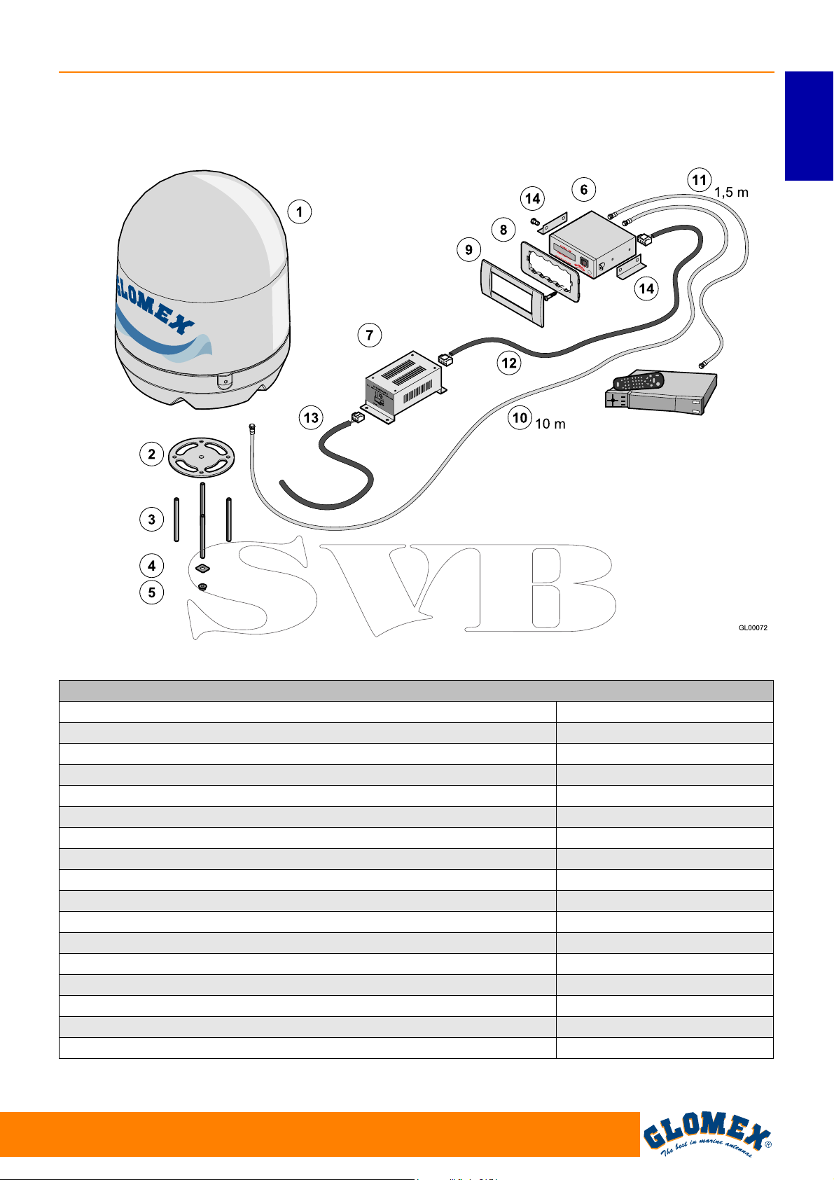
VENUS V9000 - SATURN V9100 - MARS V9801
VENUS SATURN MARS RHINE
ITALIANO
Ricevitore satellitare
(non fornito)
Fig. 1B
VENUS V9000/SATURN V9100/MARS V9801 Fig. 1B
Componente Codice GLOMEX
Unità Antenna V9000 (1) 3.010.0015
Unità Antenna V9100 (1) 3.010.0016
Unità Antenna V9801 (1) 3.010.0017
Guarnizione base (2) 4.010.0415
Barre filettate M8 x 100 (4 pz) (3) 4.100.0118
Rinforzi per il fissaggio (4 pz) (4) 4.020.0247
Dadi autobloccanti M8 (4 pz) (5) 4.100.0019
Unità di controllo (6) 4.120.0042
Alimentatore per unità di controllo (7) 4.120.0043
Supporto Vimar per fissaggio unità di controllo (8) 4.010.0153
Cornice per montaggio ad incasso (9) 4.010.0154
Cavo 10 m connessione antenna - unità di controllo (10) V9139/10
Cavo 1,5 m connessione amplificatore di linea - decoder (11) V9143
Cavo alimentazione unità di controllo - alimentatore (12) 4.070.0100
Cavo connessione alimentatore - magnetotermico quadro di bordo (13) 4.070.0101
Staffe per montaggio unità di controllo su piano (14) 4.020.0611
www.glomex.it
9
Page 12
VENUS SATURN MARS RHINE
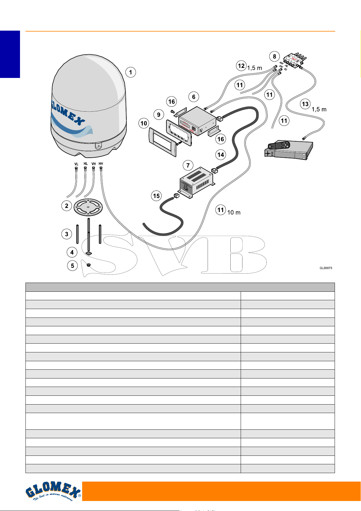
SATURN V9104 - MARS V9804 - SATURN V9104SKEW - MARS V9804SKEW
ITALIANO
Ricevitore satellitare
(non fornito)
Fig. 1C
SATURN V9104 - V9104 SKEW/MARS V9804 - V9804 SKEW Fig. 1C
Componente Codice GLOMEX
Unità Antenna V9104 (1) 3.010.0018
Unità Antenna V9104 SKEW (1) 3.010.0019
Unità Antenna V9804 (1) 3.010.0020
Unità Antenna V9804 SKEW (1) 3.010.0021
Guarnizione base (2) 4.010.0415
Barre filettate M8 x 100 (4 pz) (3) 4.100.0118
Rinforzi per il fissaggio (4 pz) (4) 4.020.0247
Dadi autobloccanti M8 (4 pz) (5) 4.100.0019
Unità di controllo (6) 4.120.0042
Alimentatore per unità di controllo (7) 4.120.0043
Multiswitch (8) V9191
Supporto Vimar per fissaggio unità di controllo (9) 4.010.0153
Cornice per montaggio ad incasso (10) 4.010.0154
Cavi 10 m connessioni antenna - unità di controllo e antenna -
multiswitch (11) (4 pz)
Cavo 1,5 m connessione unità di controllo - multiswitch (12) V9143
Cavo 1,5 m connessione multiswitch - decoder (13) V9143
Cavo alimentazione unità di controllo - alimentatore (14) 4.070.0100
Cavo connessione alimentatore - magnetotermico quadro di bordo (15) 4.070.0101
Staffe per montaggio unità di controllo su piano (16) 4.020.0611
V9139/10
10
www.glomex.it
Page 13
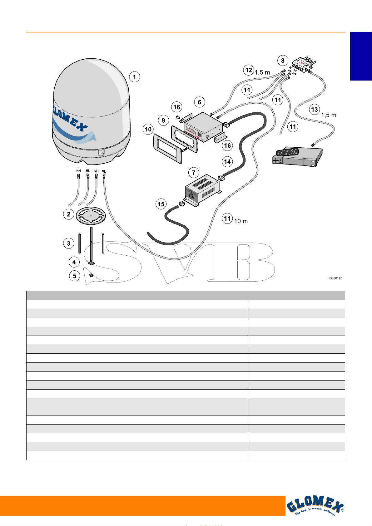
RHINE R9804
VENUS SATURN MARS RHINE
ITALIANO
Ricevitore satellitare
(non fornito)
Fig. 1D
RHINE R9804 Fig. 1D
Componente Codice GLOMEX
Unità Antenna R9804 (1) 3.010.0023
Guarnizione base (2) 4.010.0415
Barre filettate M8 x 100 (4 pz) (3) 4.100.0118
Rinforzi per il fissaggio (4 pz) (4) 4.020.0247
Dadi autobloccanti M8 (4 pz) (5) 4.100.0019
Unità di controllo (6) 4.120.0042
Alimentatore per unità di controllo (7) 4.120.0043
Multiswitch (8) V9191
Supporto Vimar per fissaggio unità di controllo (9) 4.010.0153
Cornice per montaggio ad incasso (10) 4.010.0154
Cavi 10 m connessioni antenna - unità di controllo e antenna - mul-
tiswitch (11) (4 pz)
Cavo 1,5 m connessione unità di controllo - multiswitch (12) V9143
Cavo 1,5 m connessione multiswitch - decoder (13) V9143
Cavo alimentazione unità di controllo - alimentatore (14) 4.070.0100
Cavo connessione alimentatore - magnetotermico quadro di bordo (15) 4.070.0101
Staffe per montaggio unità di controllo su piano (16) 4.020.0611
V9139/10
www.glomex.it
11
Page 14
VENUS SATURN MARS RHINE
3.1 ACCESSORI OPZIONALI (NON
INCLUSI) PER L’UTILIZZO DELLE
ANTENNE GLOMEX
ITALIANO
Per poter utilizzare la vostra nuova antenna satellitare per imbarcazioni GLOMEX, dovrete avere a
disposizione od acquistare anche:
-un televisore;
- un ricevitore satellitare per la selezione dei
canali.
La tabella sottostante elenca tutti gli accessori
opzionali GLOMEX, con relativo codice.
Accessorio opzionale Codice GLOMEX
Decoder satellitare i-CAN 1110SV TIVÙSAT
230 VAC - 12 VDC
XDome decoder combo digitale terrestre - satellitare HD (DVB-T + DVB-S + DVB-S2) compatibile
SKY ITALIA - 230 VAC
Supporto acciaio inox 0°- 5° V9500
Radome gemello V9... TWIN - R9804 TWIN
Verniciatura Radome - colore RAL a scelta dal
cliente
Amplificatore di linea V9115
V9193
V9192
SATPAINT
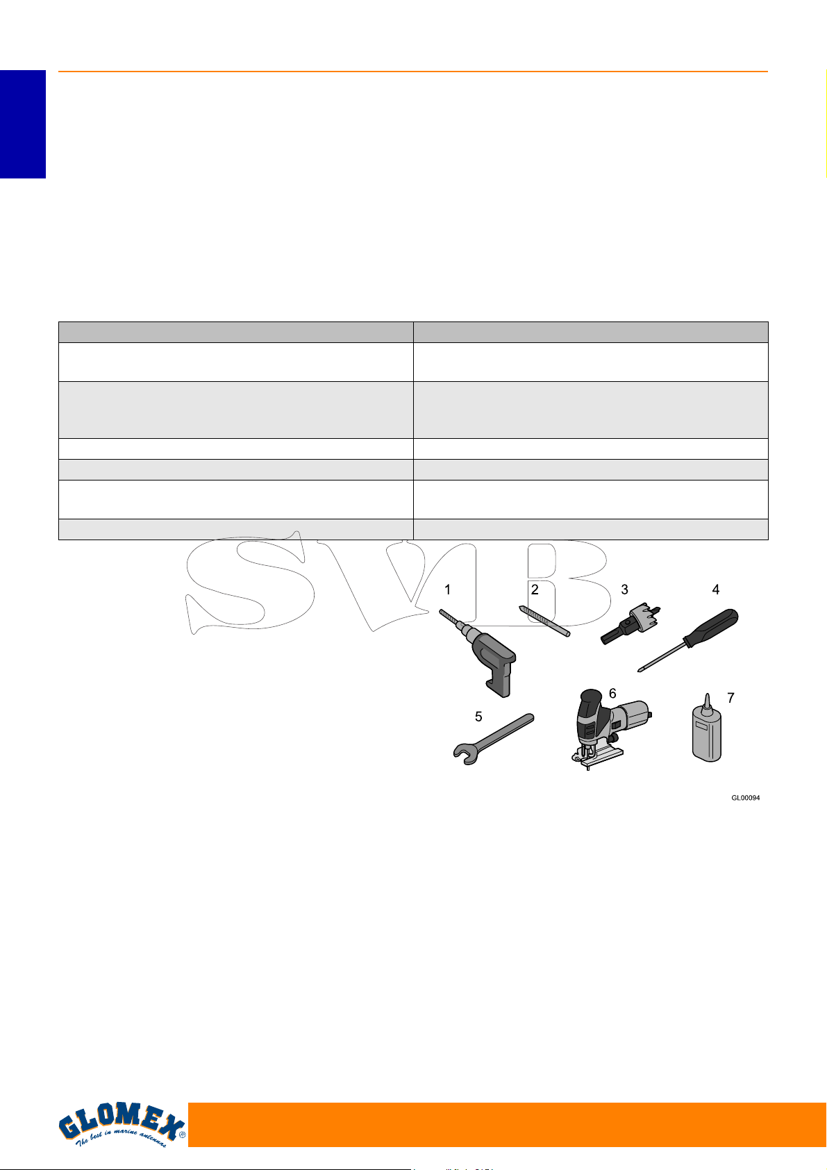
4. ATTREZZI NECESSARI PER IL
MONTAGGIO (NON FORNITI)
Recuperare tutti gli utensili e i materiali elencati di
seguito. Saranno necessari per completare l’installazione.
- Trapano elettrico (1).
- Punta da trapano da 8,5 mm per il montaggio
del radome (2).
- Fresa a tazza da 28 mm per il foro per il passag-
gio del cavo del connettore dell’antenna (3).
- Cacciavite a croce (di dimensioni adeguate per
l’installazione dell’unità di controllo) (4).
- Chiave inglese da 11 mm (per l’installazione dei
connettori dei cavi coassiali) (5).
- Seghetto alternativo (per praticare lo scasso per
l’installazione dell’unità di controllo su parete;
utilizzare il template fornito a pagina 25) (6).
- LOCTITE ® 638 (7)
Fig. 2
12
www.glomex.it
Page 15
VENUS SATURN MARS RHINE
S
Pianificare l’intera installazione prima di procedere!
Tenere in considerazione il posizionamento dei vari
componenti, la distanza tra di loro, la lunghezza dei
vari cavi, e l’accessibilità all’attrezzatura una volta
installata.
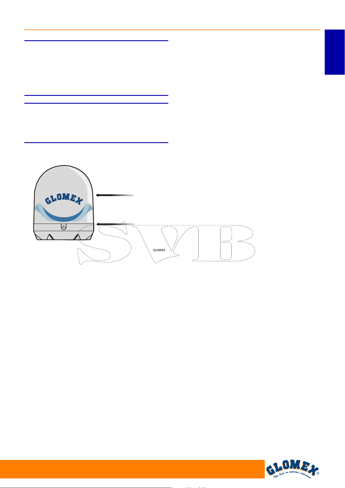
S
Sollevare sempre l’antenna dal radome inferiore e
mai dal radome superiore o qualsiasi parte
all’interno di esso.
ATTENZIONE
ATTENZIONE
Radome superiore
Radome inferiore
ITALIANO
Fig. 3
www.glomex.it
13
Page 16
VENUS SATURN MARS RHINE
5. INSTALLAZIONE
Prima di procedere con l’installazione, attenersi
alle seguenti linee guida:
ITALIANO
- tenere presente che la posizione migliore per
l’antenna TV satellitare è al centro della barca e
nel punto più basso possibile.
- minimizzare l’oscuramento. L’antenna richiede
una visuale non ostruita del cielo per ricevere i
segnali satellitari TV. Meno sono gli ostacoli frapposti, migliore sarà il funzionamento
dell’impianto.
Qualsiasi corpo estraneo (bandiere, antenne,
antenne radar, alberi di barche a vela, gru, ponti,
ecc.) che si frappone tra l’antenna ed il satellite
oscura il segnale ed impedisce la ricezione.
- accertarsi che la superficie di montaggio sia
ampia abbastanza per accogliere la base
dell’antenna.
Segnale bloccato!
- assicurarsi che la superficie di montaggio sia
resistente e rigida per poter supportare il peso
dell’antenna e le vibrazioni che si possono verificare.
- non installare l’antenna vicino ad altoparlanti o
fonti magnetiche. Nel caso in cui ciò non sia possibile è necessario compensare la fonte magnetica facendo attenzione a non interferire con la
bussola di bordo.
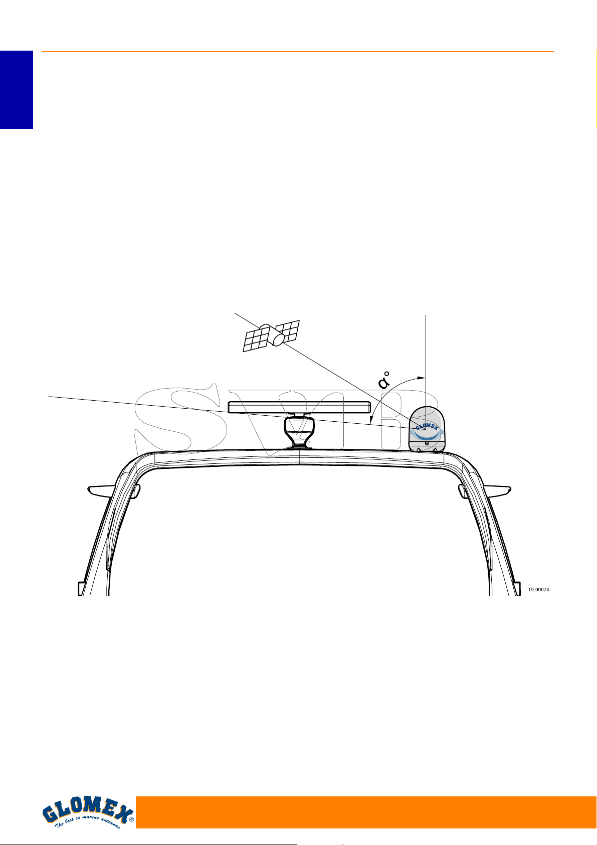
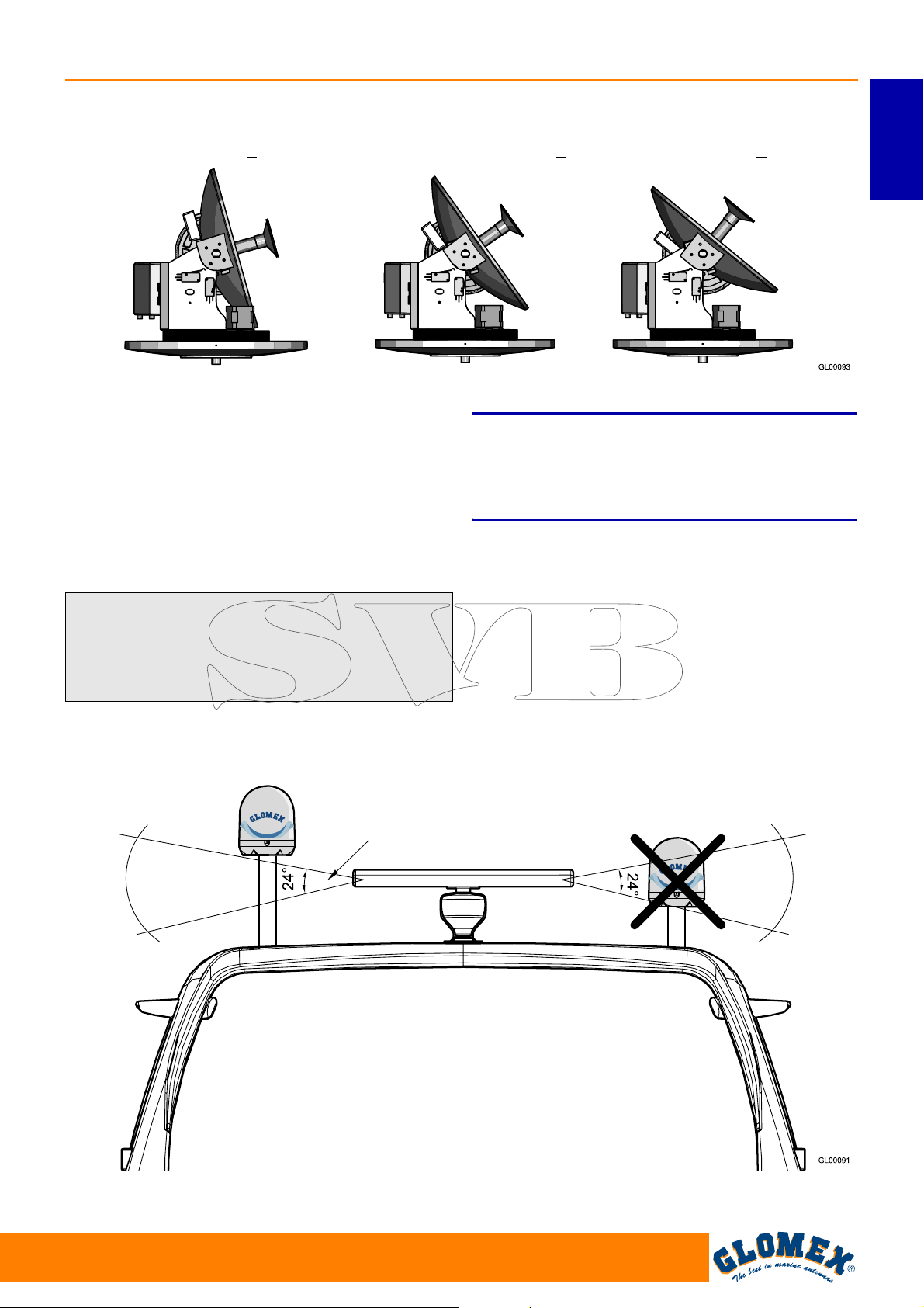
- l’antenna richiede un angolo di elevazione
compreso tra 5° e 90° per ricevere i segnali dal
satellite (Fig. 4).
α
Fig. 4
Antenna TV
Roll-bar
α = angolo di elevazione
14
www.glomex.it
Page 17
VENUS SATURN MARS RHINE
Elevazione tipica dell’antenna
NORD EUROPA (~ 15°) EUROPA CENTRALE (~ 35°) SUD EUROPA (~ 50°)
Fig. 5
- si consideri la posizione dell’antenna in relazione
alla posizione di tutte le varie attrezzature o
cablaggi all’interno dell’imbarcazione.
- l’unità di controllo dovrebbe essere montata in
una posizione conveniente per le operazioni di
regolazione. Dovrebbe trovarsi vicino all’unità
ricevitore/televisore in modo che lo schermo della
TV possa essere visto durante le operazioni effettuate sull’unità di controllo.
S
Il fascio di radiofrequenza emesso dal radar può
danneggiare l’elettronica interna dell’antenna, in
particolare l’LNB.
ATTENZIONE
ITALIANO
Si consiglia di non installare l’antenna sullo stesso
livello del radar, perché l’energia di quest’ultimo
potrebbe danneggiare l’antenna. L’antenna
dovrebbe trovarsi ad almeno 1,5 metri dalle altre
antenne trasmittenti (VHF, radar) (Fig. 6).
OK NO
Angolo di irradiazione
verticale tipico del radar
Fig. 6
www.glomex.it
15
Page 18
VENUS SATURN MARS RHINE
6. MONTAGGIO
ITALIANO
Durante le operazioni di montaggio dell’antenna
indossare gli equipaggiamenti antinfortunistici
appropriati per il lavoro.
1. Assicurarsi innanzitutto di avere scelto una
posizione corretta per il montaggio dell’antenna
(vedere sezione 5: “Installazione”).
2. Rimuovere l’antenna dalla scatola di imballag-
gio. Rimuovere le viti dal radome inferiore.
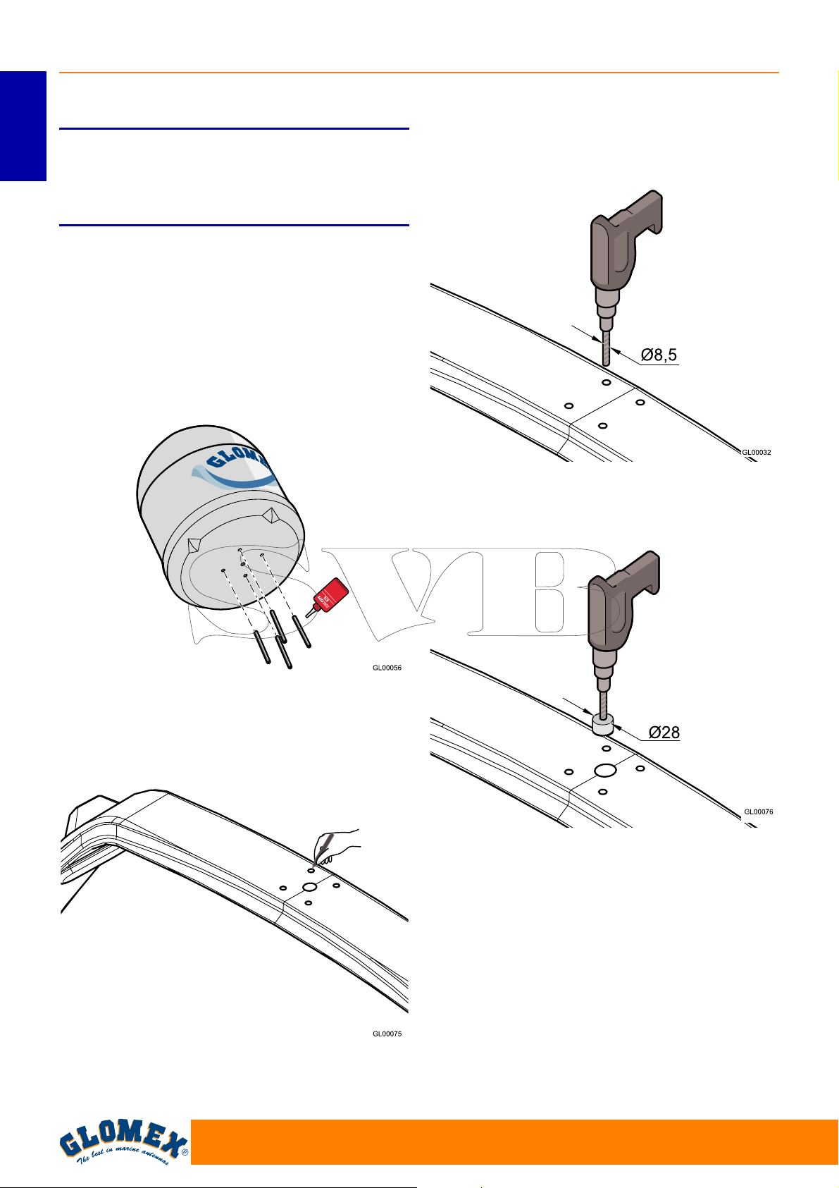
3. Inserire sotto la base dell’antenna le 4 barre
filettate M8 e utilizzare un bloccafiletti liquido
(Loctite®638).
S
PERICOLO
5. Praticare i 4 fori per il passaggio delle barre
filettate utilizzando un trapano elettrico ed una
punta da 8,5 mm sulla superficie di appoggio.
Fig. 7
4. Utilizzare la dima di foratura 6.1 a pagina 24 e
segnare con un pennarello i fori per le barre
filettate e il passaggio del cavo.
Fig. 9
6. Praticare il foro per il passaggio del cavo utilizzando il trapano elettrico ed una fresa a tazza
da 28 mm.
Fig. 10
7. Posizionare la guarnizione di gomma in modo
che i fori corrispondano.
Fig. 8
16
www.glomex.it
Page 19
VENUS SATURN MARS RHINE
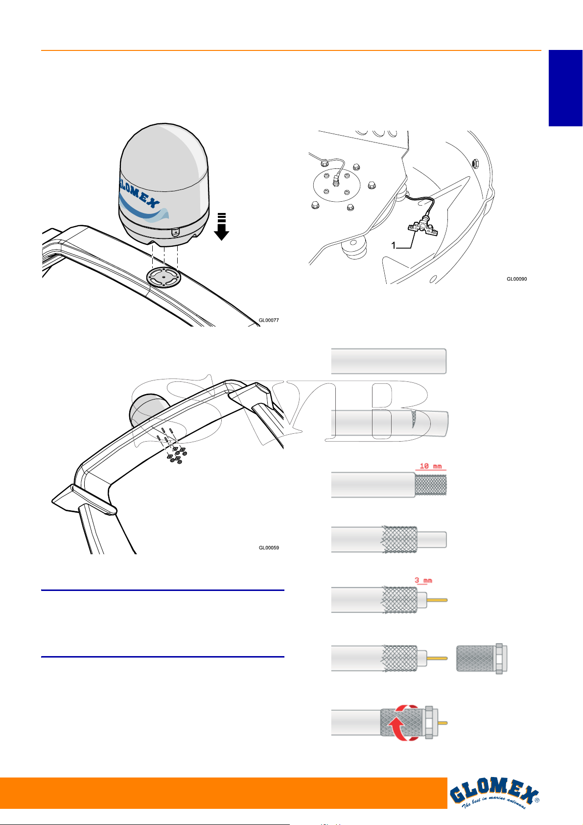
8. Posizionare l’antenna sulla guarnizione,
facendo passare le 4 barre filettate nei fori prestando attenzione a collocarla con il simbolo di
orientamento verso prua.
Fig. 11
9. Inserire i rinforzi per il fissaggio sulle barre filettate e avvitare i dadi autobloccanti M8.
13. Per connettere il cavo coassiale è necessario
rimuovere il radome superiore e connetterlo sul
connettore (1) presente sul radome inferiore,
cercando di dargli un percorso che segua la
curvatura del radome.
Fig. 13
14. Nel caso dovesse essere necessario accorciare
il cavo, fare riferimento alle istruzioni riportate in
Fig. 14.
ITALIANO
Fig. 12
10. Stringere a fondo.
S
La GLOMEX declina qualsiasi responsabilità per
uno scorretto montaggio del radome sull’imbarcazione.
11. Far passare il cavo da 10 m attraverso il foro
praticato precedentemente (V9000, V9100,
V9801).
12. Far passare i 4 cavi da 10 m attraverso il foro
praticato precedentemente (V9104,
V9104SKEW, V9804, V9804SKEW, R9804).
ATTENZIONE
www.glomex.it
GL00095
Fig. 14
17
Page 20
VENUS SATURN MARS RHINE
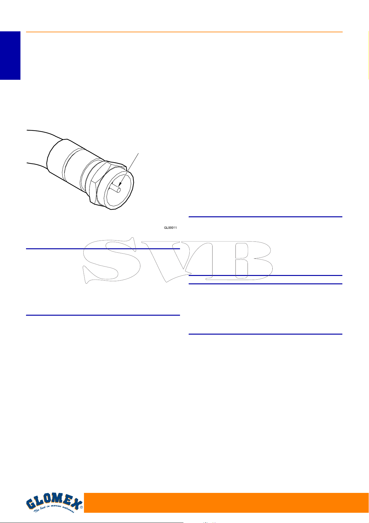
15. Assicurarsi che l’anima centrale del cavo sia
correttamente inserita nel foro centrale del connettore femmina sull’antenna.
ITALIANO
Avvitare a mano la ghiera del connettore F.
Una volta stretta a mano la ghiera serrare di ¼
di giro utilizzando una chiave inglese da 11 mm.
16. Rimuovere le due fascette di sicurezza presenti
sull’ingranaggio di azimut e di elevazione.
Conduttore centrale
del cavo coassiale
2. Individuare la posizione corretta per l’alimentatore:
- esso deve stare in una posizione vicina
all’unità di controllo;
- deve essere raggiungibile dal cavo (rosso -
nero) proveniente dalle batterie o dal quadro
di bordo;
- deve essere collocato in zona asciutta e venti-
lata (massima temperatura di funzionamento
45° C).
3. Collegare il cavo coassiale dell’antenna (precedentemente installato) nell’ingresso ANTENNA
IN sull’unità di controllo ed un cavo coassiale
tra l’uscita RECEIVER OUT sull’unità di controllo e il decoder.
Assicurarsi che le anime centrali dei cavi siano
correttamente inserite nei fori centrali dei rispettivi connettori femmina sull’unità di controllo.
Avvitare a mano le ghiere dei connettori F.
Una volta strette a mano le ghiere serrare di ¼
di giro utilizzando una chiave inglese da 11 mm.
Fig. 15
S
Per un corretto montaggio rispettare il verso di
installazione indicato in Fig. 11.
Una installazione diversa da quella consigliata
potrebbe causare un non corretto funzionamento
dell’antenna per il rischio di ingresso di acqua nel
radome.
Operazioni da eseguire all’interno dell’imbarcazione.
1. Individuare la posizione corretta per l’unità di
controllo:
- essa deve stare in una posizione vicina al
ricevitore satellitare dal momento che il cavo
coassiale fornito è lungo 1,5 metri;
- deve essere raggiungibile dal cavo di alimen-
tazione che proviene dall’alimentatore;
- deve essere raggiungibile dal cavo coassiale
proveniente dall’antenna (lungo 10 metri);
- deve essere collocata in zona asciutta e venti-
lata (massima temperatura di funzionamento
45° C).
ATTENZIONE
S
L’inversione dei due cavi pregiudica il funzionamento dell’apparecchio. Assicurarsi di aver installato correttamente i cavi coassiali. In caso di
danneggiamento GLOMEX non risponderà direttamente dei danni arrecati al ricevitore.
S
Le antenne V9000, V9100 e V9801 sono progettate per funzionare con un solo decoder; non installare quindi divisori di segnale prima o dopo l’unità
di controllo.
ATTENZIONE
ATTENZIONE
18
www.glomex.it
Page 21
VENUS SATURN MARS RHINE
Alimentatore
Retro dell’alimentatore
Dall’antenna
Rosso
Nero
Retro della Control Unit
ITALIANO
Al decoder (V9000-V9100-V9801)
Al multiswitch (V9104-V9804) HH
Al multiswitch (R9804) VL
10 ÷ 30 VDC
Fig. 16
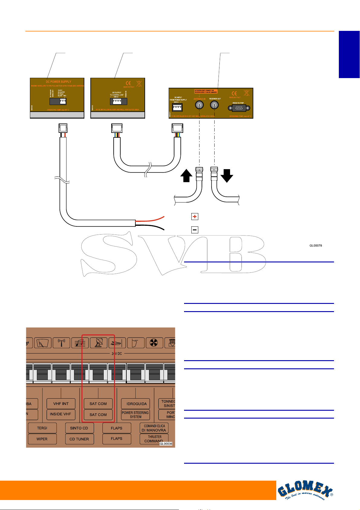
4. Collegare il cavo di alimentazione (10-30 VDC)
ad un interruttore libero della strumentazione di
bordo (min. 5A): al cavo rosso deve essere collegato il polo positivo e al cavo nero il polo
negativo. La linea di alimentazione deve avere
cavi di sezione minima di 2,5 mm
ghezza fino a 4 m, di 4 mm
superiori.
Fig. 17
2
per una lun-
2
per lunghezze
S
Non prelevare l’alimentazione da circuiti secondari.
Ciò potrebbe pregiudicare il funzionamento
dell’apparecchio.
S
Per evitare che dispersioni di corrente o accumulo
di cariche possano danneggiare le parti elettroniche dell’antenna, assicurarsi di avere un buon
impianto di massa.
S
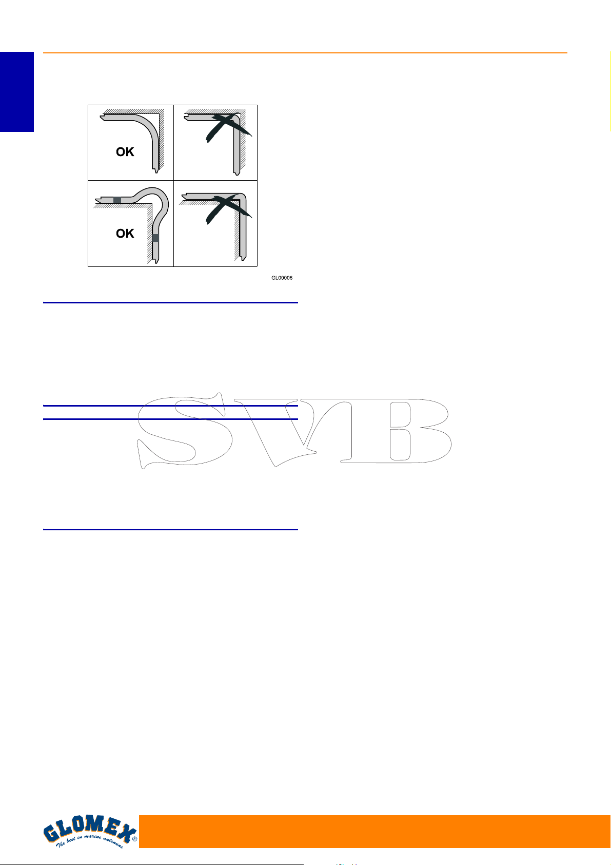
Fare attenzione a non piegare i cavi coassiali ad
angolo retto; l’angolo di curva deve essere sempre
maggiore di 120°.
NOTA (valida per V9000): nel caso fosse necessario utilizzare un cavo più lungo di 10 m per il collegamento dell’unità di controllo al ricevitore
satellitare è consigliato utilizzare l’amplificatore di
linea V9115 tra di essi.
ATTENZIONE
ATTENZIONE
ATTENZIONE
www.glomex.it
19
Page 22
VENUS SATURN MARS RHINE
ITALIANO
Fig. 18
NOTA: Non tagliare i connettori dei cavi coassiali
(non si garantirebbe più il funzionamento) ed utilizzare sempre i cavi originali GLOMEX in dotazione
anche se di dimensioni non adeguate (troppo lunghi). Non utilizzare cavi differenti, perché ciò
pregiudicherebbe il funzionamento dell’apparecchio.
S
Se l’unità di controllo visualizza il messaggio ERR1
significa che non c’è comunicazione tra antenna e
unità di controllo.
È necessario quindi verificare che il cavo di connessione tra unità di controllo e antenna sia serrato
bene e non sia interrotto o in corto circuito.
ATTENZIONE
20
www.glomex.it
Page 23
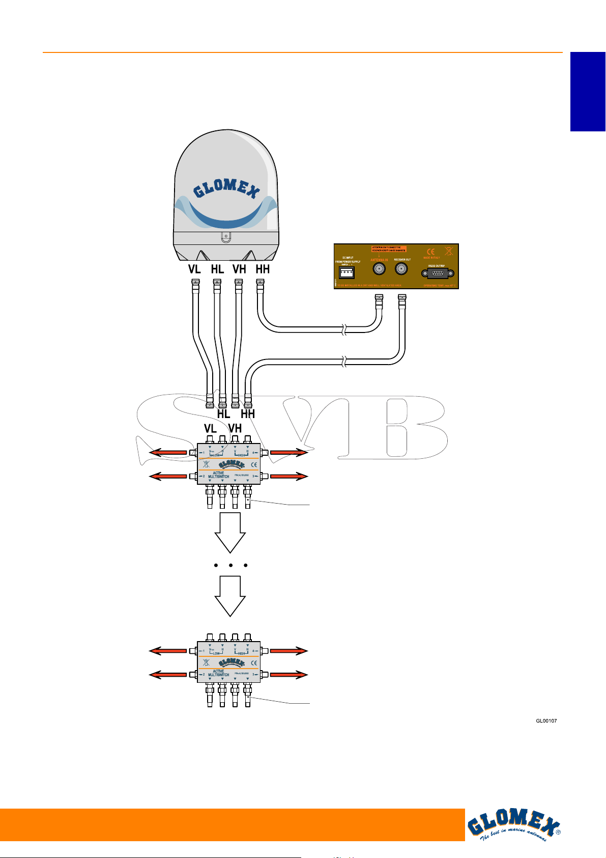
5. Per i modelli V9104, V9104SKEW, V9804 e
V9804SKEW che prevedono la presenza del
multiswitch, cablare i cavi seguendo le indicazioni di Fig. 19.
VENUS SATURN MARS RHINE
ITALIANO
Retro delle Control Unit
Fig. 19
Ricevitore
Ricevitore
Ricevitore
Ricevitore
Ricevitore
Ricevitore
Carico isolato da 75 ohm oppure al massimo
altri 3 multiswitch e sull’ultimo il carico isolato da 75 ohm.
Ricevitore
Ricevitore
Carico isolato da 75 ohm
www.glomex.it
21
Page 24
VENUS SATURN MARS RHINE
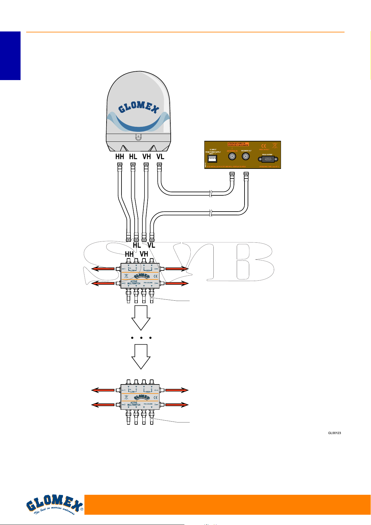
6. Per il modello R9804 cablare i cavi seguendo le
indicazioni di Fig. 20.
ITALIANO
Retro delle Control Unit
Fig. 20
Ricevitore
Ricevitore
Ricevitore
Ricevitore
Ricevitore
Ricevitore
Carico isolato da 75 ohm oppure al massimo
altri 3 multiswitch e sull’ultimo il carico isolato da 75 ohm.
Ricevitore
Ricevitore
Carico isolato da 75 ohm
22
www.glomex.it
Page 25
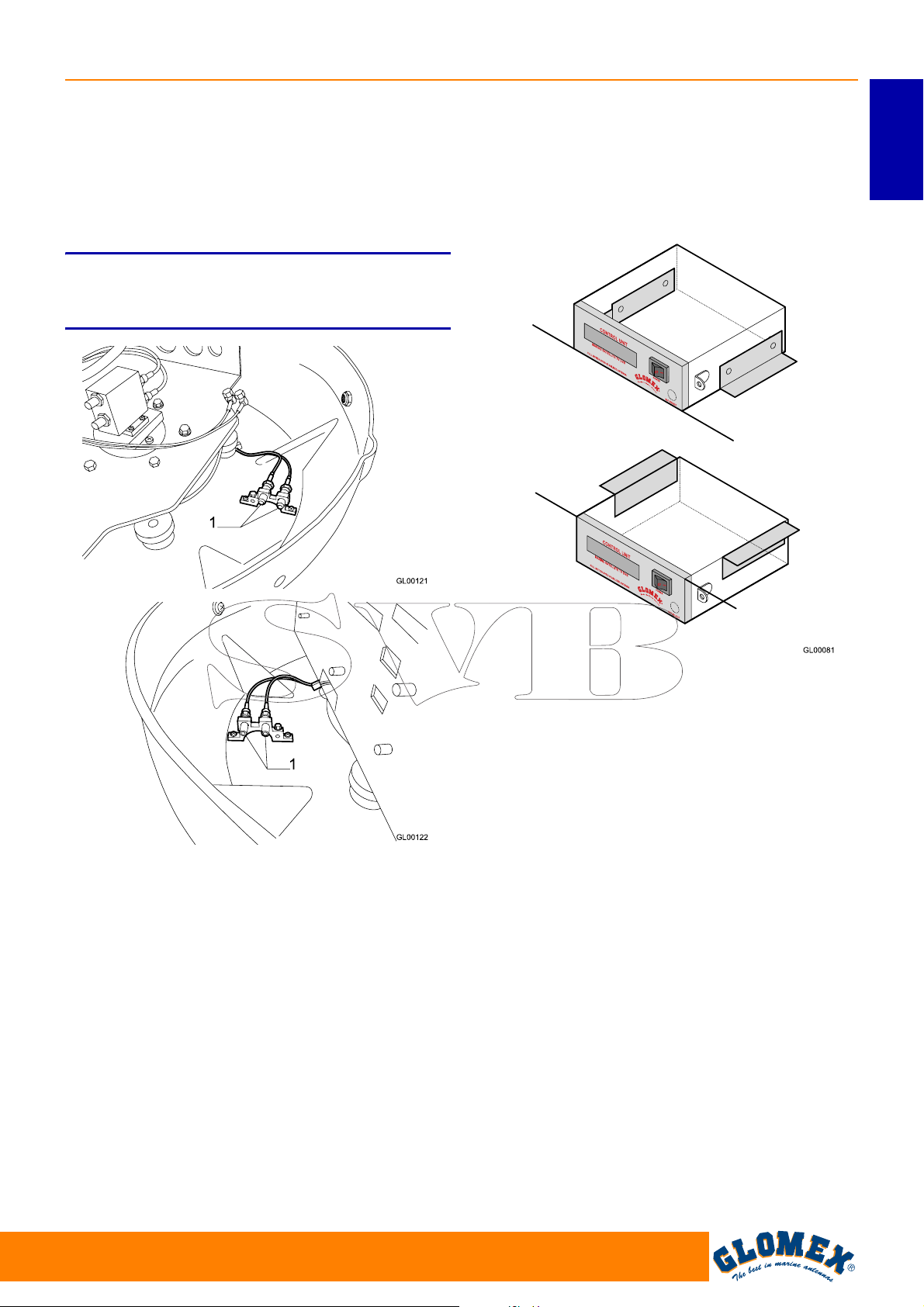
VENUS SATURN MARS RHINE
Per connettere i cavi coassiali alle prese VL, HL,
VH e HH del giunto coassiale rotante multiplo è
necessario rimuovere il radome superiore e connettere i vari cavi sui connettori (1) predisposti
all’interno del radome inferiore, cercando di dare ai
cavi un percorso che segua la curvatura del
radome.
NOTA: per alcuni modelli è presente una unica
staffa con 4 connessioni anziché 2 staffe da 2 connessioni ciascuna.
8. Procedere con la connessione dei cavi
all’amplificatore di linea (se presente), al multiswitch (se presente), al/ai ricevitore/i (non
incluso/i), come indicato nelle Fig. 1, Fig. 16,
Fig. 19.
ITALIANO
Fig. 21
7. L’unità di controllo può essere fissata ad una
parete verticale tramite l’ausilio del telaio di
®
copertura ad incastro Vimar
fornito assieme
all’antenna. Praticare in tal caso un foro con un
seghetto alternativo utilizzando come dima il
template di Fig. 23.
L’unità di controllo può essere anche fissata su
un piano orizzontale o sul soffitto. In tal caso è
necessario utilizzare le 2 staffe ad L fornite
assieme all’antenna e fissarle come indicato in
Fig. 22.
Fig. 22
www.glomex.it
23
Page 26
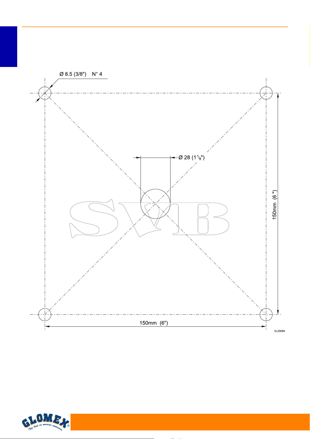
VENUS SATURN MARS RHINE
6.1 DIMA DI FORATURA RADOME INFERIORE
ITALIANO
Fig. 23
24
www.glomex.it
Page 27
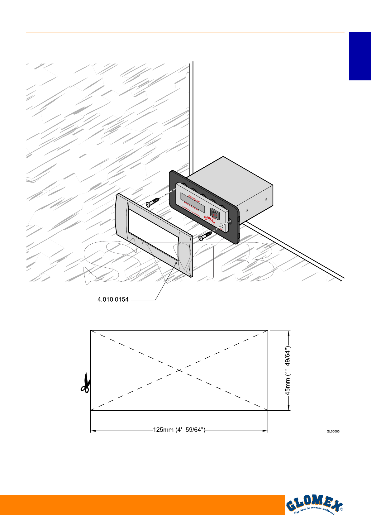
VENUS SATURN MARS RHINE
6.2 DIMA DI FORATURA CONTROL UNIT PER MONTAGGIO SU PARETE VERTICALE
ITALIANO
Fig. 24
www.glomex.it
25
Page 28
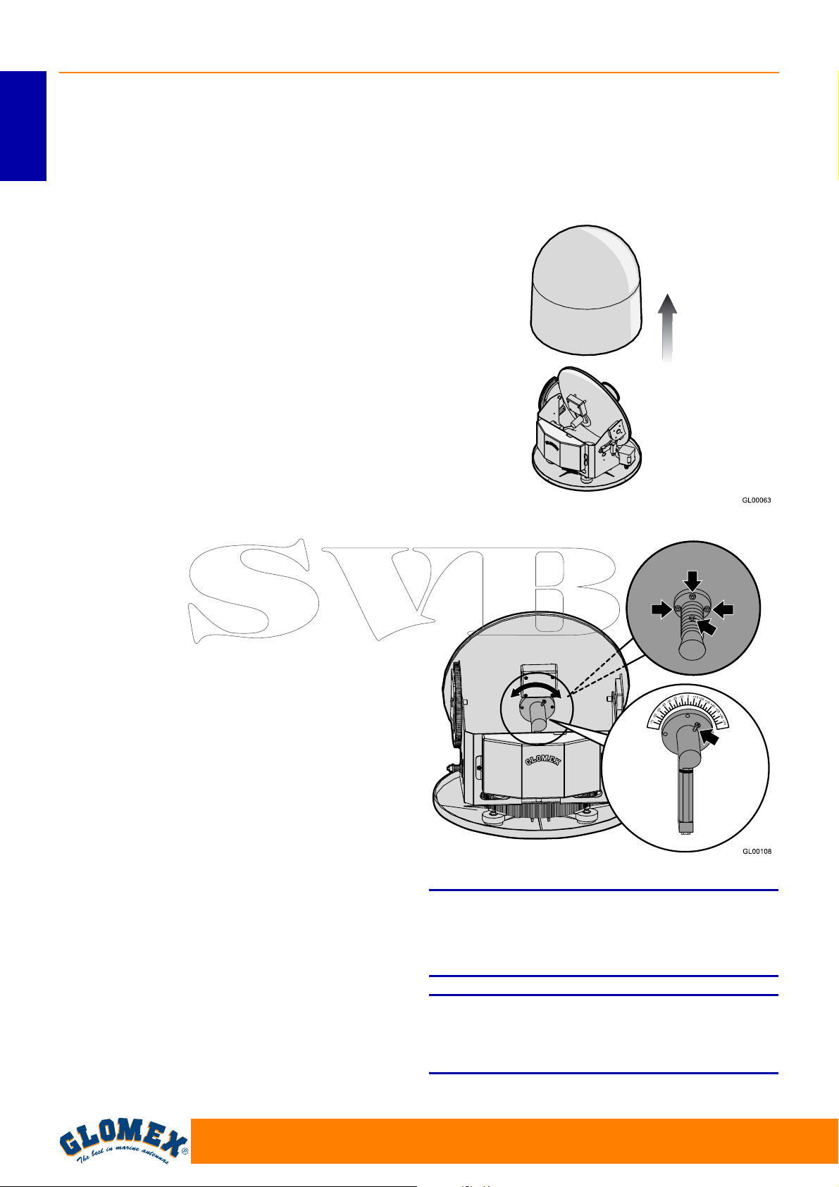
VENUS SATURN MARS RHINE
6.3 CALIBRAZIONE SKEW (MANUALE)
I Satelliti possono trasmettere in polarizzazione
lineare (Europa) o circolare (USA). Le antenne
ITALIANO
GLOMEX sono progettate per operare con una
polarizzazione di tipo lineare o circolare a seconda
dell’LNB installato in funzione del satellite che si
vuole ricevere e della posizione in cui ci si trova.
La polarizzazione circolare non richiede nessuna
calibrazione per l’ottimizzazione del segnale ricevuto.
Al contrario gli LNB che lavorano con polarizzazione lineare necessitano di calibrazione in fase di
installazione per ottimizzare l’allineamento
dell’LNB con il satellite che si intende ricevere.
Quando ci si trova alla stessa longitudine del satellite i suoi segnali orizzontali e verticali sono allineati
con l’orizzonte. Quando il satellite si trova ad est o
ad ovest della propria posizione il segnale del
satellite apparirà ruotato in senso orario o antiorario. Sia il segnale orizzontale che quello verticale si
troveranno ruotati dello stesso angolo trovandosi
quindi sempre perpendicolari tra di loro.
L’entità della rotazione dipenderà dalla distanza ad
est od ovest tra la posizione dell’antenna e il satellite e da quanto ci si trova distanti dell’equatore.
Una volta che ci si sposta in una zona con longitudine superiore a +/- 10° dalla posizione precedente
l’LNB deve essere regolato manualmente per ottenere il massimo del segnale.
Le antenne vengono consegnate con l’LNB ottimizzato per una zona con longitudine 12° Est durante
la ricezione del satellite 13° Est.
La calibrazione non deve essere più modificata
se la barca rimane nella stessa zona e riceve lo
stesso satellite.
Una volta effettuata la regolazione voluta stringere
le viti, riposizionare il radome superiore sulla sua
base e riavvitare le viti di fissaggio.
Fig. 25
4 uscite
1 uscita
Per la regolazione dell’LNB procedere come
segue:
- svitare le viti sul radome e rimuovere il radome
superiore dalla base;
- per modelli ad 1 uscita allentare la vite che tiene
bloccato l’LNB al disco (vedi Fig. 26) e muovere
manualmente lo stesso usando come riferimento
per la giusta calibrazione il parametro di signal
quality del ricevitore digitale che si sta usando
(vedi manuale del ricevitore stesso). La calibrazione non deve essere più modificata se la barca
rimane nella stessa zona e riceve lo stesso satellite.
- per modelli a 4 uscite allentare le quattro viti a
brugola che si trovano nella parte anteriore del
disco e muovere manualmente lo stesso usando
come riferimento per la giusta calibrazione il
parametro di signal quality del ricevitore digitale
che si sta usando (vedi manuale del ricevitore
stesso).
26
Fig. 26
NOTA: le operazioni appena descritte non sono da
eseguire nel caso di antenne con regolazione automatica dello SKEW!
(V9104SKEW e V9804SKEW)
S
Durante la regolazione dello SKEW fare attenzione
a non scollegare i due cavi sensori fissati all’LNB.
ATTENZIONE
www.glomex.it
Page 29
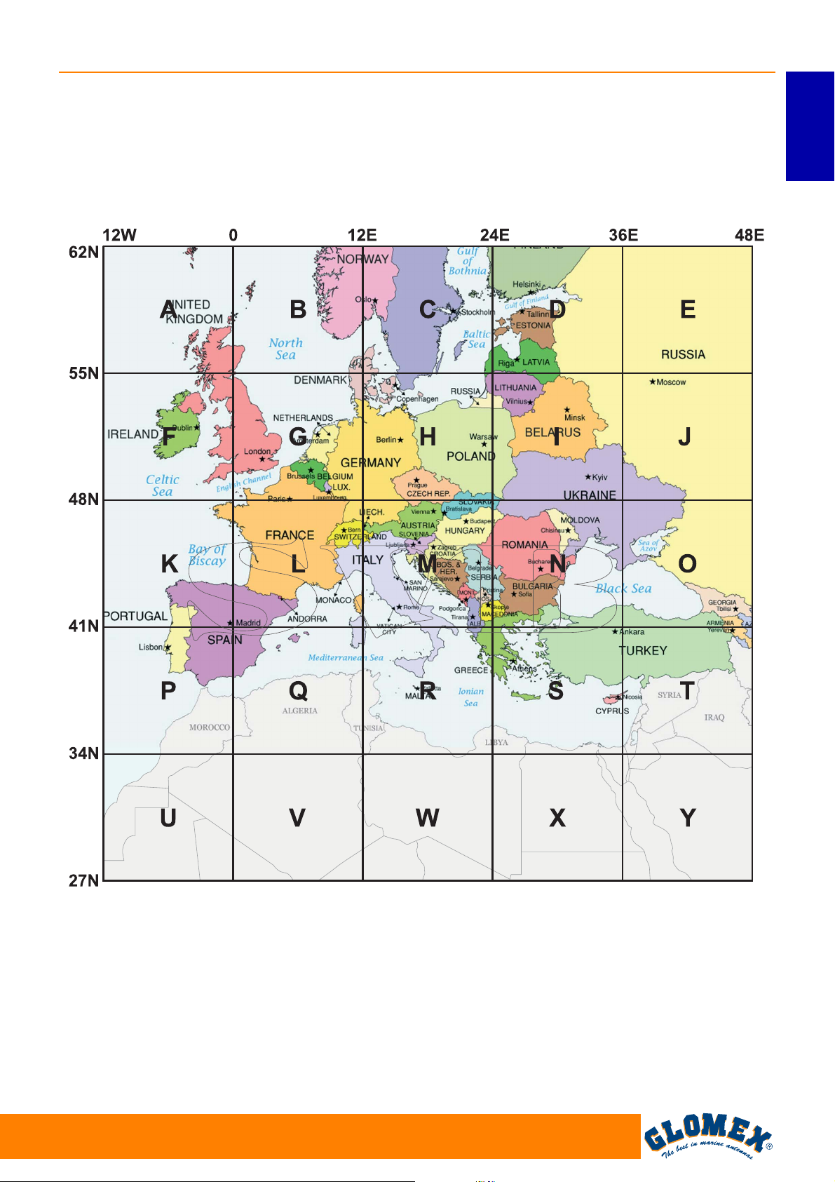
6.4 GRIGLIA DI REGOLAZIONE SKEW
EUROPA
VENUS SATURN MARS RHINE
Per determinare i valori di regolazione dell’LNB è
possibile utilizzare la griglia sottostante e la relativa
tabella.
ITALIANO
Fig. 27
Si consiglia di ricavare i valori per la regolazione
utilizzando il software (licenza gratuita) SMW Link
(distribuito dall’azienda SWEDISH MICROWAVE
AB, http://www.smw.se/smwlink.htm).
www.glomex.it
27
EGITTO
GIORDANIA
GL00096
Page 30
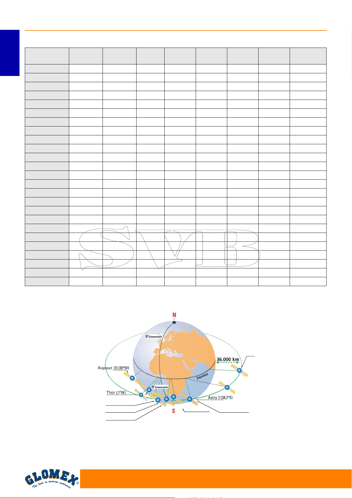
VENUS SATURN MARS RHINE
Grid position TURKSAT
42°E
ITALIANO
A (6°W 58°N) -25° -19° -18° -14° -11° -6° -3° 14°
ASTRA2
28.2°E
ASTRA3
23.5°E
ASTRA1
19.2°E
HOTBIRD
13.0°E
SIRIUS
4.8°E
THOR
1°W
B (6°E 58°N) -20° -13° -12° -8° -4° 0° 4° 20°
C (18°E 58°N) -14° -6° -4° 0° 3° 8° 11° 24
D (30°E 58°N) -7° 1° 3° 6° 10° 14° 17° 28°
E (42°E 58°N) 0° 7° 10° 13° 16° 20° 23° 30°
F (6°W 52°N) -30° -24° -21° -18° -14° -8° -3° 17°
G (6°E 52°N) -24° -16° -13° -10° -5° 0° 5° 24°
H (18°E 52°N) -17° -8° -5° 0° 3° 9° 14° 34°
I (30°E 52°N) -9° 1° 4° 8° 12° 18° 21° 36°
J (42°E 52°N) 0° 11° 12° 17° 20° 25° 28° 22°
K (6°W 45°N) -36° -29° -27° -23° -18° -10° -5° 30°
L (6°E 45°N) -30° -20° -20° -12° -7° 0° 6° 31°
M (18°E 45°N) -22° -9° -8° -1° 4° 12° 18° 36°
N (30°E 45°N) -11° 2° 5° 10° 16° 22° 27° 40°
O (42°E 45°N) 0° 13° 17° 21° 25° 31° 34° 43°
P (6°W 38°N) -43° -35° -36° -28° -22° -13° -6° 27°
Q (6°E 38°N) -37° -25° -23° -16° -8° 1° 8° 36°
R (18°E 38°N) -27° -12° -10° -1° 6° 16° 22° 43°
S (30°E 38°N) -15° 2° 8° 13° 20° 28° 33° 47°
T (42°E 38°N) 0° 17° 23° 26° 31° 37° 41° 50°
U (6°W 30°N) - -44° -43° -36° -28° -18° -8° 35°
V (6°E 30°N) - -33° -34° -21° -11° 1° 11° 45°
W (18°E 30°N) - -16° -11° -1° 8° 21° 29° 52°
X (30°E 30°N) - 3° 10° 18° 25° 36° 41° 56°
Y (42°E 30°N) - 22° 28° 34° 38° 46° 49° 58°
HISPASAT
30°W
Fig. 28
Sirius 4 (5°E)
Eurobird (9°E)
Hot-Bird (13°E)
28
Astra 1 (19,2°E)
Turksat (42°E)
Astra 3 (23,5°E)
GL00069
www.glomex.it
Page 31
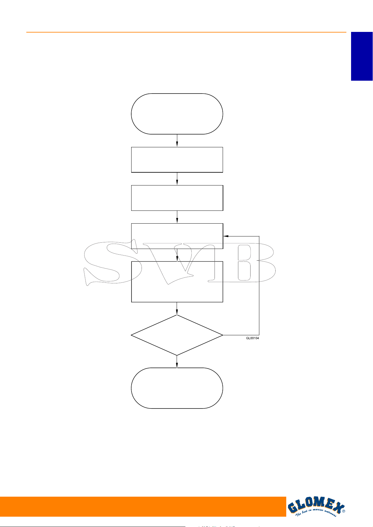
7. USO
Diagramma di flusso
VENUS SATURN MARS RHINE
ITALIANO
ACCENSIONE TASTO I
RICERCA SEGNALE
CALIBRAZIONE
RICERCA SUD
RICERCA SATELLITE
SATELLITE TROVATO
CONTROLLO E IDENTIFICAZIONE
SATELLITE
È IL SATELLITE
SELEZIONATO?
SI
SATELLITE OK
NO
Fig. 29
www.glomex.it
29
Page 32
VENUS SATURN MARS RHINE
1. Assicurarsi che l’antenna abbia una visuale
libera del cielo per ricevere i segnali dal satellite.
2. Accendere il ricevitore e il televisore. Per i det-
ITALIANO
tagli sull’utilizzo del ricevitore e del televisore
consultare i rispettivi manuali d’uso forniti dai
costruttori.
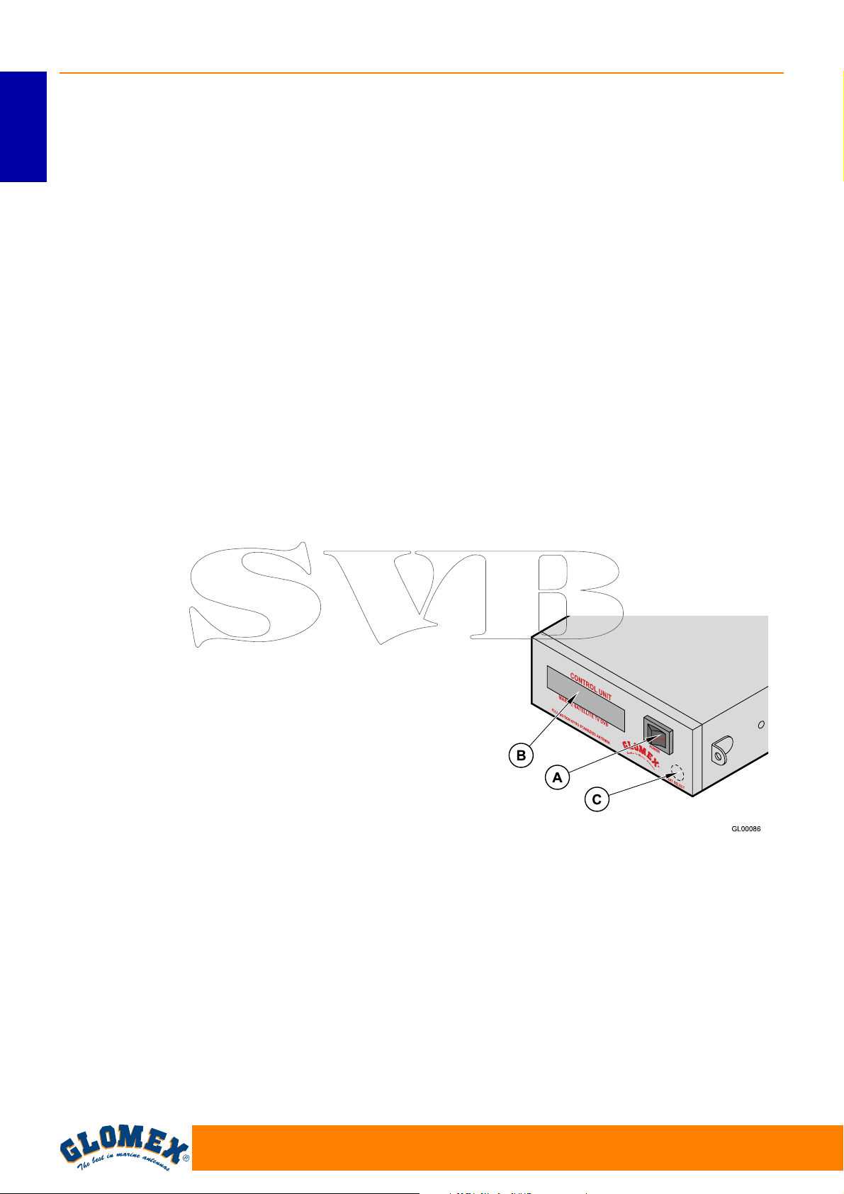
3. Per accendere l’unità di controllo agire sul tasto
(A) posizionandolo su I: automaticamente
l’antenna comunica all’unità di controllo quando
è pronta ed inizia la ricerca del satellite selezionato impiegando da un minimo di 20 secondi ad
un massimo di 2 minuti dipendenti dal movimento della barca.
4. SELEZIONE DELLA LINGUA: all’accensione,
mentre compare la scritta GLOMEX sul display
è possibile selezionare la lingua desiderata (fra
Italiano, Inglese, Francese, Spagnolo e Tedesco) premendo ripetutamente il tasto (C). Per
registrare la scelta effettuata basta spegnere e
riaccendere l’unità di controllo tramite il tasto
(A).
5. SELEZIONE DEL SATELLITE DA
RICERCARE: premere ripetutamente il tasto
(C) per la selezione del satellite fino a quando il
display alfanumerico nella prima riga (B1) corrisponde alla scelta desiderata.
I seguenti satelliti sono quelli ricevibili dall’apparecchiatura:
- ASTRA2 28.2°E
- ASTRA3 23.5°E
- ASTRA1 19.2°E
-HOTBIRD 13°E
- EUROBIRD 9°E
- SIRIUS 4.8°E
- THOR 1°W
- HISPASAT 30°W
Dopo aver selezionato il satellite desiderato
immediatamente l’antenna inizia la ricerca del
segnale indicandolo nella seconda riga del
display (B2).
6. RICERCA ED INSEGUIMENTO DEL
SEGNALE SATELLITARE: quando l’antenna
ha trovato il segnale satellitare questo viene
verificato, e in caso di successo, sul display
viene indicato “sat ok” (B2).
A volte può succedere che l’antenna riceva
prima un satellite differente da quello selezionato (dipende dalla posizione in cui ci si trova,
dalla potenza del segnale trasmesso e dalle
condizioni meteorologiche). In questo caso il
controllo del sistema NIT è negativo e immediatamente l’antenna ricomincia la ricerca del
satellite selezionato tenendo conto della posizione del satellite appena trovato. L’unità di
controllo memorizza l’ultima posizione satellitare su di essa selezionata e alla successiva
accensione inizia la ricerca per quest’ultima
posizione satellitare. Quando l’antenna è in
tracking si possono vedere i programmi TV e
ascoltare quelli RADIO per mezzo di un ricevitore ed un televisore (non forniti).
7. FUNZIONE DI RISPARMIO ENERGETICO:
quando l’imbarcazione è ormeggiata e gli spostamenti sono minimi si può attivare la funzione
di risparmio energetico che oltre a minimizzare i
consumi di corrente elettrica annulla eventuali
rumori provenienti dall’antenna. Per abilitare
questa funzione premere il tasto (C) per la selezione del satellite una sola volta (compare la
scritta sul display indicante lo stato - abilitato o
disabilitato). Per cambiare lo stato premere
nuovamente il tasto (C). Quando la funzione è
abilitata dopo circa 2 minuti che l’imbarcazione
non ha subito spostamenti, l’antenna si ferma
nella posizione del massimo segnale ricevuto
dal satellite. Un calo del livello del segnale ricevuto o uno spostamento complessivo
dell’imbarcazione di 6° in due minuti fanno
“risvegliare” l’antenna per il recupero del massimo livello di segnale ricevibile.
A. Tasto di accensione
B. Display alfabetico su due righe:
• B1 (Prima riga): nome del satellite che si
vuol ricevere
• B2 (Seconda riga): funzione in esecuzione
C. Tasto di selezione satellite e attivazione/
disattivazione sistema di risparmio energetico.
Fig. 30
30
www.glomex.it
Page 33
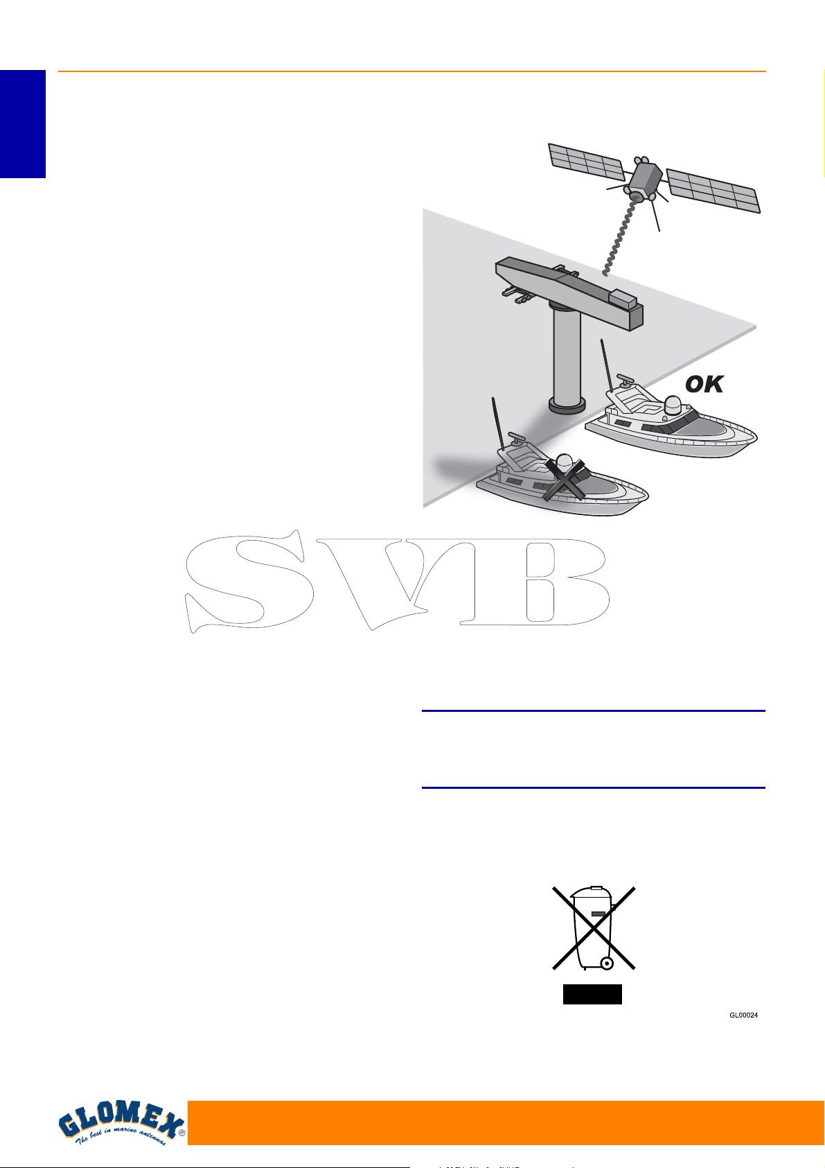
LEGENDA FUNZIONI UNITÀ DI CONTROLLO
Avvio: all’accensione dell’unità di controllo, sul
display compare la scritta
‘ GLOMEX MK2+ DVBS ’
‘ ANTENNA VX.XXX ’
VX.XXX = VERSIONE SW
ANTENNA INIT: in questa fase l’antenna si posi-
ziona per la funzione di calibrazione;
CALIBRAZIONE: fase di calibrazione dei giro-
scopi;
RICERCA SUD: rotazione dell’asse azimut che
posiziona l’antenna in direzione sud;
RICERCA SAT: ricerca del satellite; salvo interventi
da parte dell’utente, l’antenna parte automaticamente alla ricerca dell’ultimo satellite ricevuto;
SAT TROVATO: scritta che compare sul display
quando l’antenna trova il segnale di un satellite
prima di eseguire il controllo del NIT.
SEGNALE PERSO: compare in caso di perdita del
segnale;
ANT. STANDBY: compare quando l’antenna riesce
a ricevere il segnale del satellite e l’imbarcazione
rimane immobile per un determinato periodo di
tempo. In tale situazione l’antenna si ferma sul
massimo valore del segnale ricevuto riducendo i
rumori di funzionamento e il consumo energetico;
RICERCA PROX SAT: messaggio visualizzato nel
passaggio dell’antenna da un satellite all’altro,
quando il primo satellite ricevuto non corrisponde a
quello selezionato;
VERIFICA SAT: messaggio che compare quando il
satellite viene ricevuto durante la fase di controllo
del NIT;
ATTENZIONE ERR 1: non c’è comunicazione tra
antenna e unità di controllo.
SAT OK: indica che il satellite selezionato è stato
agganciato e verificato correttamente.
VENUS SATURN MARS RHINE
ITALIANO
www.glomex.it
31
Page 34
VENUS SATURN MARS RHINE
8. CONSIGLI PER UN CORRETTO UTILIZZO
La GLOMEX raccomanda di seguire le seguenti
indicazioni per un corretto utilizzo dell’apparecchio.
ITALIANO
- Il ricevitore deve essere attivato prima di ricevere la programmazione satellitare.
- Mantenere sempre il radome montato
sull’antenna. Il suo compito è quello di proteggere tutte le parti interne (fisse e in movimento)
da vento, pioggia e polveri.
- Non appoggiarsi e/o sedersi sull’antenna!
- Fare attenzione a non versare liquidi di nessun
genere all’interno dell’antenna.
- Il radome dovrebbe essere pulito periodicamente. La polvere o la sporcizia accumulatesi
sopra il radome potrebbero influire sulla ricezione satellitare. Pulire il radome con un panno
umido d’acqua. NON UTILIZZARE SPAZZOLE,
ABRASIVI, DETERSIVI O LIQUIDI A BASE
ALCOLICA.
- Non verniciare la superficie del radome! Ciò
influenzerebbe negativamente la ricezione del
segnale.
- L’antenna deve avere una visione non ostruita
del cielo per poter ricevere i segnali dal satellite.
Possibili cause molto comuni di un bloccaggio
del segnale includono alberi di altre imbarcazioni, ponti, equipaggiamenti di bordo, ecc. Le
antenne GLOMEX inoltre non funzionano
all’interno di strutture di rimessaggio.
GL00045
Fig. 31
- La pioggia forte o la neve potrebbero temporaneamente interrompere la ricezione del segnale
dal satellite.
- L’imbarcazione deve trovarsi all’interno dell’area
di copertura del satellite selezionato per ricevere
il segnale desiderato. Consultare le mappe di
copertura satellitare a pagina 34.
S
Condizioni meteo avverse influenzano la qualità
del segnale e riducono la qualità delle immagini!
- Alla fine della sua vita, non disperdere l’antenna
o parti di essa nell’ambiente, ma rivolgersi ad
agenzie di smaltimento rifiuti specializzate.
Fig. 32
ATTENZIONE
32
www.glomex.it
Page 35
8.1 FOOTPRINT: AREE DI TRASMISSIONE
DEI SATELLITI
VENUS SATURN MARS RHINE
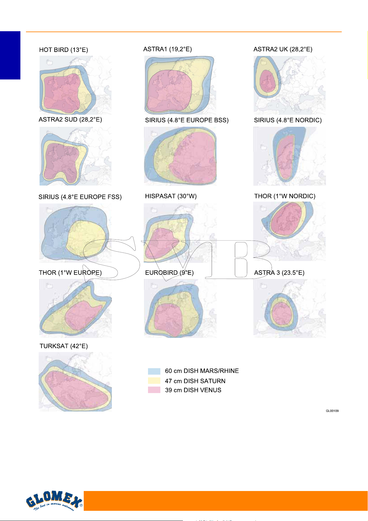
La televisione via satellite è uno di pochi mezzi che
permettono di ricevere informazioni in qualsiasi
parte del mondo ci si trovi all’interno della zona di
copertura del satellite che si desidera ricevere.
Il segnale trasmesso dal satellite ha generalmente
un’ampia zona di copertura come mostrato dai grafici puramente indicativi riportati alla pagina
seguente e quindi garantisce la visione degli stessi
programmi televisivi in varie zone.
È comunque importante ricordare che gli ostacoli a
terra sono le principali cause di malfunzionamento
delle antenne satellitari.
Per ostacoli a terra s’intendono tutti i corpi fisici che
possono venirsi a trovare nel mezzo tra il satellite e
l’antenna, come ad esempio alberi di altre imbarcazioni, ponti, equipaggiamenti di bordo, ecc.
Il segnale trasmesso dal satellite è anche influenzato dalle condizioni atmosferiche (sistemi nuvolosi
temporaleschi o nuvole di ghiaccio).
Nei footprint riportati sono illustrate le zone di
copertura dei satelliti sulla terra utilizzando le
antenne satellitari GLOMEX.
ITALIANO
S
In caso di maltempo i segnali saranno più deboli,
pertanto la qualità delle immagini potrà diminuire
fino a svanire completamente. È inoltre importante
accertarsi al momento dell’acquisto che le dimensioni dell’antenna satellite siano le più idonee per
ricevere il segnale nelle vostre zone di vacanza. I
footprint sono indicativi e riferiti al satellite con
E.I.R.P (Equivalent Isotropic Radiated Power) più
forte.
ATTENZIONE
www.glomex.it
33
Page 36
VENUS SATURN MARS RHINE
ITALIANO
Fig. 33
34
www.glomex.it
Page 37
9. MANUTENZIONE
VENUS SATURN MARS RHINE
9.1 MANUTENZIONE PREVENTIVA
Le antenne GLOMEX richiedono una manutenzione preventiva minima.
I seguenti accorgimenti sono sufficienti per mantenere prestazioni elevate dell’apparecchio.
Controlli mensili
- Lavare la superficie del radome con un panno
umido d’acqua fresca; non indirizzare direttamente acqua in pressione sul radome.
S
Non utilizzare spazzole, abrasivi, detersivi o liquidi
a base alcolica.
Controlli annuali
- Verificare le condizioni esterne del radome.
Pulire dalla polvere e dalla sporcizia se necessario.
Controlli prima di ogni lunga uscita
- Verificare che l’antenna sia fissata corretta-
mente.
ATTENZIONE
Se doveste avere problemi nel funzionamento o
avere bisogno di assistenza tecnica, contattate
prima di tutto il Rivenditore autorizzato. Tenete
accanto il numero di serie della vostra antenna
(riportato a pagina 2 di questo manuale) e una lista
con i sintomi dei guasti. Se un Rivenditore non
dovesse essere disponibile, contattare il Centro
Assistenza della GLOMEX (consultare la sezione
“Supporto Tecnico”).
S
Il numero di serie della vostra antenna vi sarà
richiesto durante qualsiasi telefonata di servizio o
di diagnosi inconvenienti. Il numero di serie è riportato a pagina 2 del manuale d’uso della vostra
antenna (vedere pag. 5 per indicazioni numero di
serie).
S
Conservare con cura il manuale d’installazione e
d’uso, poiché al suo interno è inserito il numero di
serie della vostra antenna!
ATTENZIONE
ATTENZIONE
ITALIANO
S
Prima di ogni operazione di manutenzione, pulizia
o dopo ogni utilizzo, spegnere SEMPRE l’antenna
dall’interruttore posto sull’unità di controllo o dal
quadro di bordo.
9.2 PARTI DI RICAMBIO
La tabella seguente elenca i codici dei componenti
che possono essere forniti a ricambio direttamente
dal Rivenditore.
Radome inferiore VENUS V9000 V9000-LR
Radome superiore VENUS V9000 V9000-UR
Radome inferiore SATURN V9100 V9100-LR
Radome superiore SATURN V9100 V9100-UR
Radome inferiore SATURN V9104 V9104-LR
Radome superiore SATURN V9104 V9104-UR
Radome inferiore MARS V9801 V9801-LR
Radome superiore MARS V9801 V9801-UR
Radome inferiore MARS V9804 V9804-LR
Radome superiore MARS V9804 V9804-UR
Radome inferiore RHINE R9804 R9804-LR
Radome superiore RHINE R9804 R9804-UR
PERICOLO
Componente Codice GLOMEX
www.glomex.it
35
Page 38
VENUS SATURN MARS RHINE
10. DIAGNOSI INCONVENIENTI
Quando si manifesta un malfunzionamento al vostro
sistema di ricezione satellitare è molto importante
ITALIANO
riuscire a fare rapidamente un’indagine per capirne
la natura e per trovare, se possibile, il rimedio.
Per analizzare un malfunzionamento è opportuno
effettuare le seguenti verifiche:
- il malfunzionamento è stato generato da errore
umano;
- il malfunzionamento è dovuto ad un problema
atmosferico;
- il malfunzionamento è dovuto ad un guasto
dell’apparato stesso oppure è causato da un’anomalia di un altro apparato esterno, ma ad esso in
qualche modo legato;
- il malfunzionamento in che fase si manifesta:
all’accensione, nel funzionamento a regime, allo
spegnimento dell’apparato;
- il malfunzionamento è ripetitivo; se sì con quale
criterio;
- il malfunzionamento cosa determina dal punto di
vista funzionale;
- il malfunzionamento produce segnalazioni o no
(luminose) e/o rumori anomali (quali sibili, ronzii,
ecc.) o no e/o odori anomali (odore di bruciato) o
no;
- il malfunzionamento interferisce sul funzionamento di altri apparati;
- il malfunzionamento è un guasto effettivo apparente (ovvero in grado di annullarsi ad esempio
con lo spegnimento e successiva riaccensione
dell’apparecchio).
Quanto meglio si sarà in grado di rispondere alle
suddette domande, tanto più approfondita risulterà
l’analisi del malfunzionamento.
Nella seguente tabella vengono analizzate le cause
più probabili che possono portare a malfunzionamenti della vostra antenna satellitare GLOMEX. Per
ogni causa possibile analizzata viene proposto un
intervento correttivo per risolvere efficacemente, e
per quanto possibile, l’inconveniente.
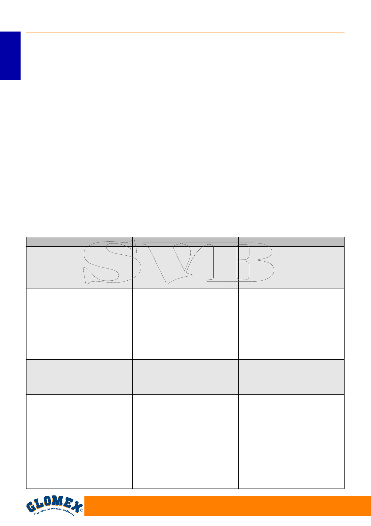
Anomalia Causa Rimedio
1. L’unità di controllo visualizza il
messaggio ERR1
2. L’antenna non funziona - errato cablaggio alimentazione - verificare la polarità sulla linea
3. Nessun messaggio di stato
sul decoder
4. Nessuna immagine sulla TV - il ricevitore è spento - spegnere l’unità di controllo,
- mancanza di collegamento tra
unità di controllo e l’antenna
- cavo coassiale in corto circuito - verificare il corretto montaggio
- guasto vero e proprio - contattare il Centro Assistenza
- il cavo coassiale si è allentato
o è sconnesso dall’antenna
- guasto interno - contattare il Centro Assistenza
- il ricevitore satellitare non è
correttamente installato
- fluttuazioni di corrente alternata
- la TV è spenta o non è stata
sintonizzata su AV
- errato cablaggio sul ricevitore - verificare che la presa SCART
- la lista canali non è aggiornata - effettuare la ricerca automatica
- verificare che il cavo di connessione tra antenna ed unità
di controllo sia serrato bene e
non sia interrotto o in corto circuito
di alimentazione
dei cavi coassiali
- verificare il collegamento dei
cavi coassiali
- verificare il collegamento del
ricevitore
- far riferimento al manuale d’uso
del ricevitore per l’assistenza
accendere il ricevitore e quindi
riaccendere l’unità di controllo
- accendere la TV e sintonizzare
il canale su AV
tra TV e ricevitore sia correttamente installata
dei canali dal menù del ricevitore
36
www.glomex.it
Page 39
VENUS SATURN MARS RHINE
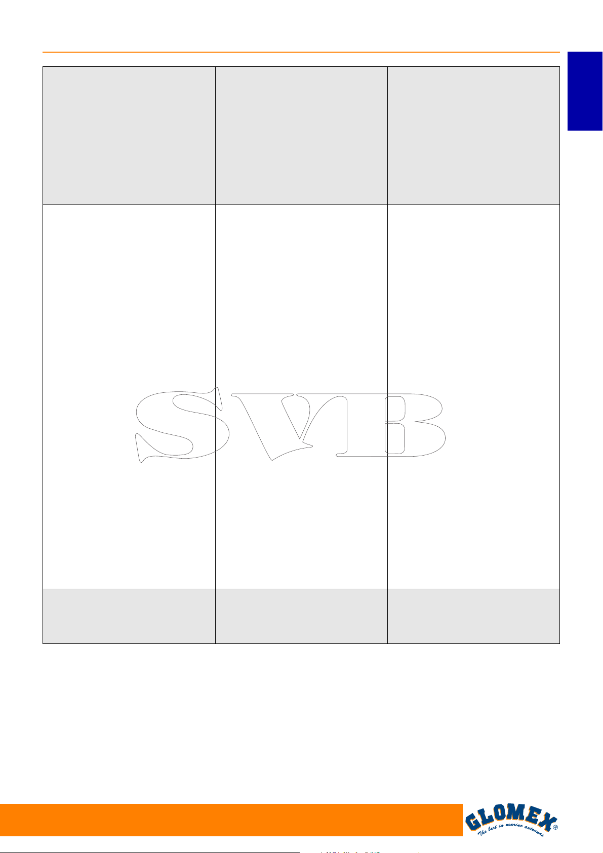
5. Immagini intermittenti per
brevi periodi
6. L’apparecchio non trova il
satellite
7. Immagini disturbate - guasto all’apparecchio ricevi-
- i segnali dal satellite sono
bloccati da alberi di altre
imbarcazioni, ponti, equipaggiamenti di bordo, ecc.
- l’imbarcazione si trova ai confini della zona di copertura
- cattive condizioni atmosferiche
- errata regolazione dello SKEW - regolare lo SKEW seguendo le
- i segnali dal satellite sono
bloccati da alberi di altre
imbarcazioni, ponti, equipaggiamenti di bordo, ecc.
- l’imbarcazione è fuori dalla
zona di copertura del segnale
- l’imbarcazione sta virando nei
primi 60 secondi di avvio
dell’apparecchio
- cattive condizioni atmosferiche
- guasto interno - contattare il Centro Assistenza
- i segnali dal satellite sono
bloccati da alberi di altre
imbarcazioni, ponti, equipaggiamenti di bordo, ecc.
- il software dell’apparecchio
non è aggiornato
- errata regolazione dello SKEW - regolare lo SKEW seguendo le
- sono variati parametri nella
comunicazione satellitare
tore
- spostare l’imbarcazione per
permettere una visuale non
ostruita all’antenna
ITALIANO
- rientrare nella zona di copertura; far riferimento alle mappe
delle zone di copertura a
pagina 34 di questo manuale
istruzioni di pagina 26
- spostare l’imbarcazione per
permettere una visuale non
ostruita all’antenna oppure
posizionare correttamente
l’antenna sull’imbarcazione
- rientrare nella zona di copertura; far riferimento alle mappe
delle zone di copertura a
pagina 34 di questo manuale
- spegnere l’apparecchio per 10
secondi, riaccenderlo e accertarsi che l’imbarcazione sia
ferma o si muova in linea retta
per i primi 60 secondi
dall’accensione
- spostare l’imbarcazione per
permettere una visuale non
ostruita all’antenna
- contattare il Centro Assistenza per richiedere l’aggiornamento del software
istruzioni di pagina 26
- contattare il Centro Assistenza per richiedere l’aggiornamento del software
- far riferimento al manuale
d’uso del ricevitore per l’assistenza, i ricambi e le condizioni di garanzia.
www.glomex.it
37
Page 40
VENUS SATURN MARS RHINE
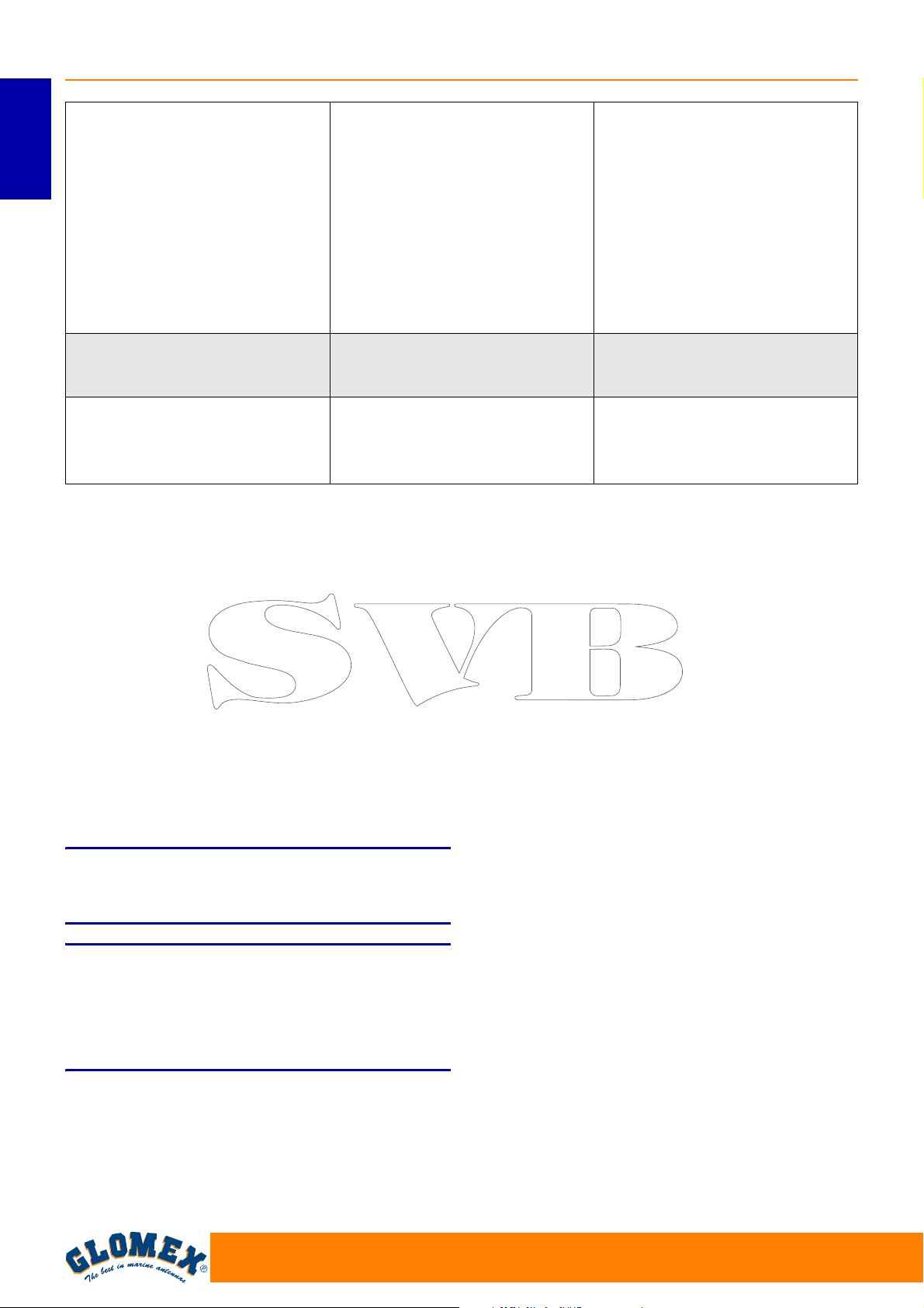
8. Immagini confuse, incomplete, bloccate
- condensa o pioggia depositatasi sul radome che può disturbare il segnale
ITALIANO
- cattive condizioni atmosferiche - applicare periodicamente un
- errata regolazione dello SKEW - regolare lo SKEW seguendo le
9. Il decoder si blocca - fluttuazioni di corrente alternata
10. L’apparecchio funziona a
imbarcazione ferma ma non in
movimento
Per maggiori informazioni consultare il Centro Assistenza GLOMEX (vedere sezione “Supporto tecnico”).
- il segnale satellitare è bloccato - allontanarsi dai possibili osta-
- guasto al sistema di giroscopi - contattare il Centro Assistenza
- rimuovere i depositi di condensa dal radome con un
getto di acqua fresca (non in
pressione)
detergente liquido per stoviglie
(non a base alcolica) alla
superficie del radome e
lasciarlo asciugare
istruzioni di pagina 26
- far riferimento al manuale
d’uso del ricevitore per l’assistenza
coli che bloccano il segnale
satellitare
11. RISPEDIZIONE
Se doveste avere la necessità di rispedire
l’antenna alla GLOMEX, posizionatela all’interno di
una scatola, possibilmente l’originale, assicurando
bene l’imballaggio ed in modo da identificare chiaramente il lato superiore od inferiore.
Per evitare che l’antenna possa danneggiarsi
durante il trasporto è necessario fissarla al radome
inferiore tramite 4 viti M8x10.
Insieme all’antenna è necessario spedire anche
l’unità di controllo in modo da poter verificare
l’intero sistema.
NOTA: La GLOMEX non risponderà di eventuali
danni avvenuti durante il trasporto per un imballaggio scorretto.
S
Non spedire l’antenna alla GLOMEX per riparazione senza aver ricevuto l’autorizzazione al reso
(RMA), come riportato nelle condizioni generali di
garanzia/assistenza.
ATTENZIONE
38
www.glomex.it
Page 41
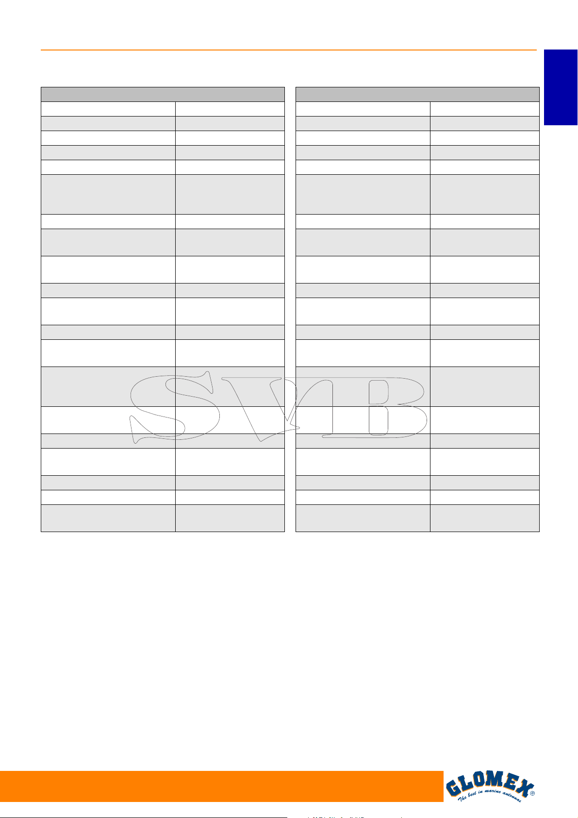
12. SPECIFICHE TECNICHE
VENUS SATURN MARS RHINE
VENUS V9000
Diametro disco antenna 39 cm
Dimensione radome 42 x 50 cm
Peso antenna 10,0 kg
Velocità di inseguimento 50° sec
Guadagno antenna 33 db - 12 GHz
PRIME FOCUS
Tipo disco
Polarizzazione Lineare (H + V)
LNB
Tipo radome
Potenza necessaria 12/24 V DC (2 A/h)
Gamma temperatura di
funzionamento
Gamma rotazione azimuth Illimitata
Gamma innalzamento
completa
Tipo di stabilizzazione
Identificazione satellite
EIRP min. 50 dBW
Predisposto per
aggiornamento futuro
Uscita decoder 1 uscita
Autoskew NO
Unità di controllo
10,7 GHz / 12,75
Resistente ai raggi
-20 °C +55 °C
giroscopio + 3° asse
per interpolazione
identification table)
8 satelliti caricati:
vedere pagina 30
+
HPD
GHz
U.V.
5° - 90°
Su 2 assi con
NIT (Network
Sì
SATURN1 V9100
Diametro disco antenna 47 cm
Dimensione radome 50 x 56 cm
Peso antenna 12,5 kg
Velocità di inseguimento 50° sec
Guadagno antenna 35 db - 12 GHz
PRIME FOCUS
Tipo disco
Polarizzazione Lineare (H + V)
LNB
Tipo radome
Potenza necessaria 12/24 V DC (2,5 A/h)
Gamma temperatura di
funzionamento
Gamma rotazione azimuth Illimitata
Gamma innalzamento
completa
Tipo di stabilizzazione
Identificazione satellite
EIRP min. 49 dBW
Predisposto per
aggiornamento futuro
Uscita decoder 1 uscita
Autoskew NO
Unità di controllo
10,7 GHz / 12,75
Resistente ai raggi
-20 °C +55 °C
giroscopio + 3° asse
per interpolazione
identification table)
8 satelliti caricati:
vedere pagina 30
+
HPD
GHz
U.V.
5° - 90°
Su 2 assi con
NIT (Network
Sì
ITALIANO
www.glomex.it
39
Page 42
VENUS SATURN MARS RHINE
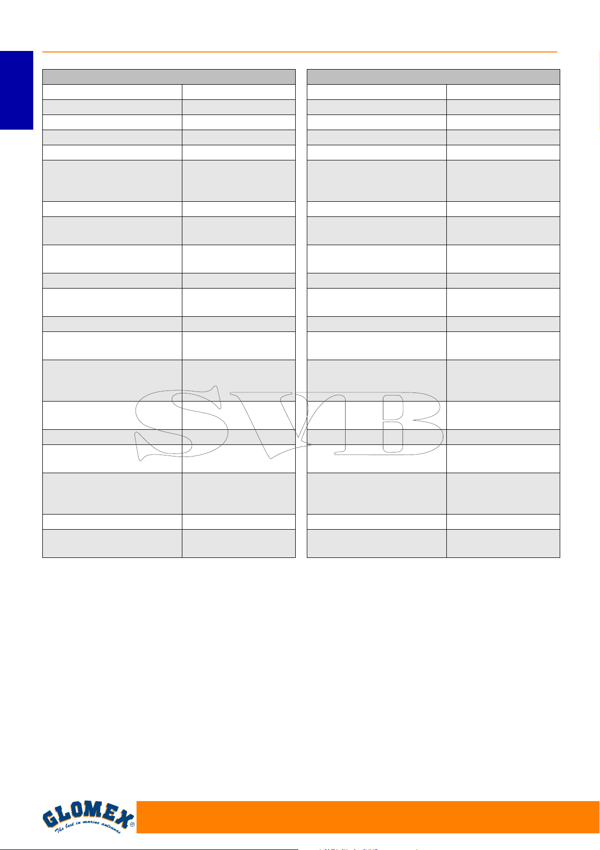
SATURN4 V9104
Diametro disco antenna 47 cm
Dimensione radome 50 x 56 cm
ITALIANO
Peso antenna 13,0 kg
Velocità di inseguimento 50° sec
Guadagno antenna 35 db - 12 GHz
PRIME FOCUS
Tipo disco
Polarizzazione Lineare (H + V)
LNB
Tipo radome
Potenza necessaria 12/24 V DC (2,5 A/h)
Gamma temperatura di
funzionamento
Gamma rotazione azimuth Illimitata
Gamma innalzamento
completa
Tipo di stabilizzazione
Identificazione satellite
EIRP min. 49 dBW
Predisposto per
aggiornamento futuro
Uscita decoder
Autoskew NO
Unità di controllo
10,7 GHz / 12,75
Resistente ai raggi
-20 °C +55 °C
giroscopio + 3° asse
per interpolazione
identification table)
4 uscite al multiswitch
8 satelliti caricati:
vedere pagina 30
+
HPD
GHz
U.V.
5° - 90°
Su 2 assi con
NIT (Network
Sì
(16 uscite al
massimo)
SATURN4 V9104SKEW
Diametro disco antenna 47 cm
Dimensione radome 50 x 56 cm
Peso antenna 13,0 kg
Velocità di inseguimento 50° sec
Guadagno antenna 35 db - 12 GHz
PRIME FOCUS
Tipo disco
Polarizzazione Lineare (H + V)
LNB
Tipo radome
Potenza necessaria 12/24 V DC (2,5 A/h)
Gamma temperatura di
funzionamento
Gamma rotazione azimuth Illimitata
Gamma innalzamento
completa
Tipo di stabilizzazione
Identificazione satellite
EIRP min. 49 dBW
Predisposto per
aggiornamento futuro
Uscita decoder
Autoskew SI
Unità di controllo
10,7 GHz / 12,75
Resistente ai raggi
-20 °C +55 °C
giroscopio + 3° asse
per interpolazione
identification table)
4 uscite al multiswitch
8 satelliti caricati:
vedere pagina 30
+
HPD
GHz
U.V.
5° - 90°
Su 2 assi con
NIT (Network
Sì
(16 uscite al
massimo)
40
www.glomex.it
Page 43
VENUS SATURN MARS RHINE
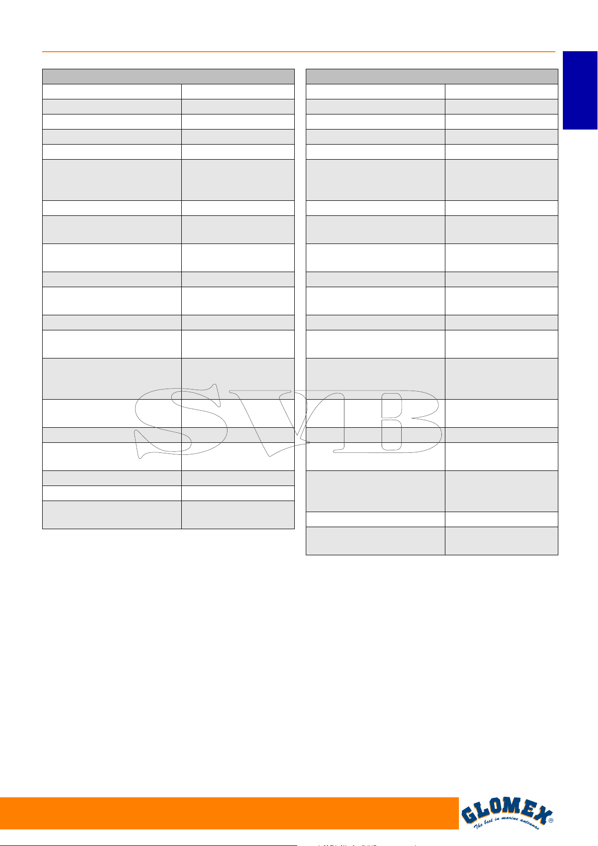
MARS1 V9801
Diametro disco antenna 60 cm
Dimensione radome 66 x 66 cm
Peso antenna 15,0 kg
Velocità di inseguimento 50° sec
Guadagno antenna 36,5 db - 12 GHz
PRIME FOCUS
Tipo disco
Polarizzazione Lineare (H + V)
LNB
Tipo radome
Potenza necessaria 12/24 V DC (2,5 A/h)
Gamma temperatura di
funzionamento
Gamma rotazione azimuth Illimitata
Gamma innalzamento
completa
Tipo di stabilizzazione
Identificazione satellite
EIRP min. 47 dBW
Predisposto per
aggiornamento futuro
Uscita decoder 1 uscita
Autoskew NO
Unità di controllo
10,7 GHz / 12,75
Resistente ai raggi
-20 °C +55 °C
giroscopio + 3° asse
per interpolazione
identification table)
8 satelliti caricati:
vedere pagina 30
+
HPD
GHz
U.V.
5° - 90°
Su 2 assi con
NIT (Network
Sì
MARS4 V9804
Diametro disco antenna 60 cm
Dimensione radome 66 x 66 cm
Peso antenna 15,5 kg
Velocità di inseguimento 50° sec
Guadagno antenna 36,5 db - 12 GHz
PRIME FOCUS
Tipo disco
Polarizzazione Lineare (H + V)
LNB
Tipo radome
Potenza necessaria 12/24 V DC (2,5 A/h)
Gamma temperatura di
funzionamento
Gamma rotazione azimuth Illimitata
Gamma innalzamento
completa
Tipo di stabilizzazione
Identificazione satellite
EIRP min. 47 dBW
Predisposto per
aggiornamento futuro
Uscita decoder
Autoskew NO
Unità di controllo
10,7 GHz / 12,75
Resistente ai raggi
-20 °C +55 °C
giroscopio + 3° asse
per interpolazione
identification table)
4 uscite al multiswitch
8 satelliti caricati:
vedere pagina 30
+
HPD
GHz
U.V.
5° - 90°
Su 2 assi con
NIT (Network
Sì
(16 uscite al
massimo)
ITALIANO
www.glomex.it
41
Page 44
VENUS SATURN MARS RHINE
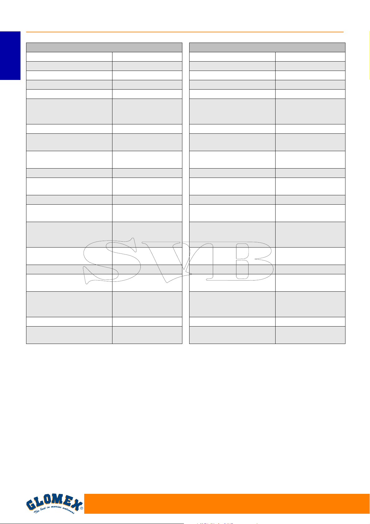
MARS4 V9804SKEW
Diametro disco antenna 60 cm
Dimensione radome 66 x 66 cm
ITALIANO
Peso antenna 15,5 kg
Velocità di inseguimento 50° sec
Guadagno antenna 36,5 db - 12 GHz
PRIME FOCUS
Tipo disco
Polarizzazione Lineare (H + V)
LNB
Tipo radome
Potenza necessaria 12/24 V DC (2,5 A/h)
Gamma temperatura di
funzionamento
Gamma rotazione azimuth Illimitata
Gamma innalzamento
completa
Tipo di stabilizzazione
Identificazione satellite
EIRP min. 47 dBW
Predisposto per
aggiornamento futuro
Uscita decoder
Autoskew SI
Unità di controllo
10,7 GHz / 12,75
Resistente ai raggi
-20 °C +55 °C
giroscopio + 3° asse
per interpolazione
identification table)
4 uscite al multiswitch
8 satelliti caricati:
vedere pagina 30
+
HPD
GHz
U.V.
5° - 90°
Su 2 assi con
NIT (Network
Sì
(16 uscite al
massimo)
RHINE R9804
Diametro disco antenna 60 cm
Dimensione radome 66 x 66 cm
Peso antenna 15,5 kg
Velocità di inseguimento 25° sec
Guadagno antenna 36,5 db - 12 GHz
PRIME FOCUS
Tipo disco
Polarizzazione Lineare (H + V)
LNB
Tipo radome
Potenza necessaria 12/24 V DC (5 A/h)
Gamma temperatura di
funzionamento
Gamma rotazione azimuth Illimitata
Gamma innalzamento
completa
Tipo di stabilizzazione
Identificazione satellite
EIRP min. 47 dBW
Predisposto per
aggiornamento futuro
Uscita decoder
Autoskew NO
Unità di controllo
10,7 GHz / 12,75
Resistente ai raggi
-20 °C +55 °C
giroscopio + 3° asse
per interpolazione
identification table)
4 uscite al multiswitch
8 satelliti caricati:
vedere pagina 30
+
HPD
GHz
U.V.
5° - 90°
Su 2 assi con
NIT (Network
Sì
(16 uscite al
massimo)
13. SUPPORTO TECNICO
Se avete bisogno di un supporto tecnico,
gentilmente contattate il CENTRO ASSISTENZA
GLOMEX:
Glomex Divisione Marine
Via Faentina 165/G
48124 Ravenna (Italia)
Tel. +39 0544 1935911
Fax +39 0544 500420
Email: [email protected]
42
www.glomex.it
Page 45
VENUS V9000
SATURN V9100 V9104 V9104SKEW
MARS V9801 V9804 V9804SKEW
RHINE R9804
SATELLITE TV ANTENNAS
FOR MARINE AND RIVER BOATS
SERIES MK2+
USER AND INSTALLATION MANUAL
Page 46
VENUS SATURN MARS RHINE
ENGLISH
44
www.glomex.it
Page 47
VENUS SATURN MARS RHINE
INDEX
1. FOREWORD . . . . . . . . . . . . . . . . . . . . . . . . . . . . . . . . . . . . . . . . . . . . . . . . . . . . . . . . . . . 47
1.1 DELIVERY LETTER. . . . . . . . . . . . . . . . . . . . . . . . . . . . . . . . . . . . . . . . . . . . . . . . . . . . 47
1.2 ANTENNA IDENTIFICATION. . . . . . . . . . . . . . . . . . . . . . . . . . . . . . . . . . . . . . . . . . . . . 47
1.3 WARRANTY. . . . . . . . . . . . . . . . . . . . . . . . . . . . . . . . . . . . . . . . . . . . . . . . . . . . . . . . . . 47
1.4 GENERAL SAFETY INSTRUCTIONS . . . . . . . . . . . . . . . . . . . . . . . . . . . . . . . . . . . . . . 48
1.5 ENVIRONMENT. . . . . . . . . . . . . . . . . . . . . . . . . . . . . . . . . . . . . . . . . . . . . . . . . . . . . . . 48
2. PRODUCT DESCRIPTION . . . . . . . . . . . . . . . . . . . . . . . . . . . . . . . . . . . . . . . . . . . . . . . . 49
2.1 VENUS V9000 - SATURN V9100 - MARS V9801 . . . . . . . . . . . . . . . . . . . . . . . . . . . . . 49
2.2 SATURN V9104 - V9104SKEW - MARS V9804 - V9804SKEW . . . . . . . . . . . . . . . . . . 49
2.3 RHINE R9804. . . . . . . . . . . . . . . . . . . . . . . . . . . . . . . . . . . . . . . . . . . . . . . . . . . . . . . . . 49
3. CONTENTS . . . . . . . . . . . . . . . . . . . . . . . . . . . . . . . . . . . . . . . . . . . . . . . . . . . . . . . . . . . . 50
3.1 OPTIONAL ACCESSORIES (NOT INCLUDED) TO USE GLOMEX ANTENNAS. . . . . 54
4. NECESSARY TOOLS FOR ASSEMBLY (NOT PROVIDED) . . . . . . . . . . . . . . . . . . . . . . 54
5. INSTALLATION . . . . . . . . . . . . . . . . . . . . . . . . . . . . . . . . . . . . . . . . . . . . . . . . . . . . . . . . . 56
6. ASSEMBLY . . . . . . . . . . . . . . . . . . . . . . . . . . . . . . . . . . . . . . . . . . . . . . . . . . . . . . . . . . . . 58
6.1 LOWER RADOME CUTTING TEMPLATE. . . . . . . . . . . . . . . . . . . . . . . . . . . . . . . . . . . 66
6.2 CONTROL UNIT CUTTING TEMPLATE FOR INSTALLATION
ON A VERTICAL WALL . . . . . . . . . . . . . . . . . . . . . . . . . . . . . . . . . . . . . . . . . . . . . . . . . 67
6.3 SKEW CALIBRATION (MANUAL) . . . . . . . . . . . . . . . . . . . . . . . . . . . . . . . . . . . . . . . . . 68
6.4 SKEW ADJUSTMENT GRID FOR EUROPE . . . . . . . . . . . . . . . . . . . . . . . . . . . . . . . . . 69
7. USE . . . . . . . . . . . . . . . . . . . . . . . . . . . . . . . . . . . . . . . . . . . . . . . . . . . . . . . . . . . . . . . . . . 71
8. TIPS FOR CORRECT USAGE . . . . . . . . . . . . . . . . . . . . . . . . . . . . . . . . . . . . . . . . . . . . . 74
8.1 FOOTPRINTS: SATELLITE TRANSMISSION AREAS . . . . . . . . . . . . . . . . . . . . . . . . . 75
ENGLISH
9. MAINTENANCE. . . . . . . . . . . . . . . . . . . . . . . . . . . . . . . . . . . . . . . . . . . . . . . . . . . . . . . . . 77
9.1 PREVENTIVE MAINTENANCE . . . . . . . . . . . . . . . . . . . . . . . . . . . . . . . . . . . . . . . . . . . 77
9.2 SPARE PARTS . . . . . . . . . . . . . . . . . . . . . . . . . . . . . . . . . . . . . . . . . . . . . . . . . . . . . . . 77
10. TROUBLESHOOTING. . . . . . . . . . . . . . . . . . . . . . . . . . . . . . . . . . . . . . . . . . . . . . . . . . . . 78
11. RESHIPPING. . . . . . . . . . . . . . . . . . . . . . . . . . . . . . . . . . . . . . . . . . . . . . . . . . . . . . . . . . . 80
12. TECHNICAL SPECIFICATIONS . . . . . . . . . . . . . . . . . . . . . . . . . . . . . . . . . . . . . . . . . . . . 81
13. TECHNICAL SUPPORT . . . . . . . . . . . . . . . . . . . . . . . . . . . . . . . . . . . . . . . . . . . . . . . . . . 84
www.glomex.it
45
Page 48

VENUS SATURN MARS RHINE
ENGLISH
46
www.glomex.it
Page 49
1. FOREWORD
VENUS SATURN MARS RHINE
1.1 DELIVERY LETTER
Welcome: with the installation of this antenna, the
world of satellite television comes on board your
boat.
This manual has been drafted in order to help you
with the correct installation and operation of the
antenna.
1.2 ANTENNA IDENTIFICATION
When calling GLOMEX or an authorized Service
Centre, always provide the serial number and the
model of the antenna, shown on the second page
of the manual, on the packaging, on the backside
of the dish, under the control unit and under the
power supply.
1.3 WARRANTY
GLOMEX guarantees the satellite antennas series
VENUS V9000, SATURN V9100, V9104 and
V9104SKEW, MARS V9801, V9804, V9804SKEW
and RHINE R9804 against conformity defects for a
period of 24 (twenty-four) months from the date of
shipment.
Warranty is intended as the repair or replacement
of the equipment showing conformity defects when
entering the sales contract, with no charge for the
materials.
In case of conformity defects, the customer is entitled to the replacement of the goods with no
charge.
The warranty is only valid if the product comes
with a valid proof of purchase, (receipt or
invoice).
The non-conforming product must be sent back to
a Service Centre or authorized retailer, who will forward it to:
GLOMEX S.r.l.
Via Faentina 165/G
48124, Ravenna (Italy)
The serial number must neither be erased nor
made illegible, otherwise the warranty will be
voided.
S
Conserve the installation and user manual with
care! Losing the serial number makes the warranty
null and void!
The warranty does not apply in case of damage
due to carelessness, use or installation not compliant with the instructions given, tampering, product
or serial number modification, damage due to accidental causes or to the buyer’s negligence.
Moreover, warranty does not apply in case of damage consequent to connections of the equipment to
different voltages than those indicated or to sudden
voltage variations of the network the equipment is
connected to, as well as in case of damage caused
by leakage, fire, inductive/electrostatic discharges
or discharges due to lightning, use of cables different to those provided, overvoltages or other phenomena not related to the equipment.
The parts subject to wear consequent to use such
as connection cables, driving belts, connectors,
external parts and plastic supports are covered by
a one-year period warranty.
The warranty does not include: periodical checks,
software updates, product settings, maintenance.
After the expiration of the warranty period, the technical support activities will be carried out charging
the customer for the replaced parts, the labour
costs and freight charges, according to current
rates.
The equipment will be replaced or repaired
under warranty only and exclusively on Glomex
quality department’s approval.
Should any dispute rise, the place of jurisdiction will
exclusively be Ravenna (Italy).
WARNING
ENGLISH
along with all the accessories supplied at purchase.
The warranty is provided by:
GLOMEX S.r.l.
Via Faentina 165/G
48124 Ravenna (Italy)
www.glomex.it
47
Page 50
VENUS SATURN MARS RHINE
1.4 GENERAL SAFETY INSTRUCTIONS
Carefully read the instructions given and follow the
precautions indicated to prevent potential hazards
and to safeguard your health and safety, before
carrying out any installation and maintenance operation.
This manual contains the following indications:
ENGLISH
This symbol warns against potential damage to the
equipment which could involve the operator’s
safety.
S
S
With specific warnings against potential dangers
for the safety of the operator or other directly
involved persons.
Failure to comply with the instructions preceded by
the above-mentioned keywords (WARNING and
DANGER) can cause serious accidents or even
the death of the persons involved.
Moreover, in this Manual, some instructions are
given with text in italics, preceded by the words
NOTE.
The information and specifications given in this
manual are based upon the information available at
the moment it is written.
In case of doubts, do not hesitate to contact
GLOMEX S.r.l.
WARNING
DANGER
1.5 ENVIRONMENT
Do not throw the appliance away with the normal
household waste at the end of its life, but hand it in
at an official point for recycling. By doing this, you
will help preserve the environment.
Fig. 1
48
www.glomex.it
Page 51
2. PRODUCT DESCRIPTION
VENUS SATURN MARS RHINE
2.1 VENUS V9000 - SATURN V9100 MARS V9801
They are satellite TV antennas that guarantee
renewed performance in satellite signal reception
and tracking when cruising, when riding the anchor
and when moored.
They are provided with the new HPD (High-Performance Dish) parabolic dish, combined with the
innovative STO (Silent Tracking Operation) noise
reduction system.
They are equipped with an efficient compensation
system of the boat’s rolling and pitching movements consisting of electronic gyro-stabilizers
(EGS) and a single coaxial rotating joint (CRJ),
which allows the antenna to stabilize signal reception by turning infinitely on the azimuth axis, with no
need to wind the single coaxial cable (SCC). They
allow connecting one receiver at a time.
They are also equipped with a control unit which
can be embedded into the on-board electric panel.
8 satellites are already available on the control unit
and are recognized through the NIT (Network Identification Table) system.
They are prearranged for future updating.
2.2 SATURN V9104 - V9104SKEW - MARS
V9804 - V9804SKEW
They are satellite TV antennas that not only guarantee high performance standards in signal reception and tracking while cruising, when riding the
anchor and when moored, but also allow the connection of up to 16 independent decoders on the
same boat.
They are provided with the new HPD (High-Performance Dish) parabolic dish, combined with the
innovative STO (Silent Tracking Operation) noise
reduction system.
They are equipped with an efficient compensation
system of the boat’s rolling and pitching movements consisting of electronic gyro-stabilizers
(EGS), a multiple coaxial rotating joint (MCRJ) and
a multiswitch box for the connection of more independent decoders (4 outputs for multiswitch, up to
a maximum quantity of 16 per antenna).
The antenna can turn infinitely around its axis,
since no coaxial cable winding and no interruption
of TV reception are needed. They are equipped
with a control unit which can be embedded into the
on-board electric panel.
In the SKEW version, they are provided with the
innovative compensation system which, according
to the geographic position, directly operates on the
LNB, automatically changing its inclination and
optimizing polarization to obtain the best possible
signal quality.
8 satellites are already available on the control unit
and are recognized through the NIT (Network Identification Table) system.
They are prearranged for future updating.
2.3 RHINE R9804
Rhine R9804 is the best satellite TV antenna for
river boats designed by Glomex. Identical in dimensions to Mars V9804 (dish diameter 600 mm), it
allows the connection of up to 16 independent
decoders on the same boat. This antenna is
equipped with a multiple coaxial rotating joint
(MCRJ) and with a multiswitch box for the connection of more independent decoders (4 outputs for
multiswitch, up to a maximum quantity of 16 per
antenna). Rhine R9804 has been designed to
obtain an outstanding performance in river navigation thanks to the new hardware and software of
mobile inspiration, which prevent losing the satellite
TV signal even in the presence of bridges and
obstacles along the banks. These characteristics
make Rhine the ideal choice to watch TV in river
boats and in case of bad weather conditions.
It is designed for future updates.
ENGLISH
www.glomex.it
49
Page 52

VENUS SATURN MARS RHINE
3. CONTENTS
The satellite antenna is sent packed in a cardboard
box and sealed with the GLOMEX “SAFETY SEAL”
hoop, which has the function of CONTENT WARRANTY seal.
Upon receipt, check that:
- the packaging is whole and the warranty hoop is
present;
- the supply matches the order specifications;
ENGLISH
- the antenna and its accessories are not dam-
aged.
In case of damage or missing parts, immediately
inform the Retailer, if possible with appropriate
photos.
The following tables list the components contained
in the package, indicating the quantities and the
GLOMEX code (if provided).
50
www.glomex.it
Page 53
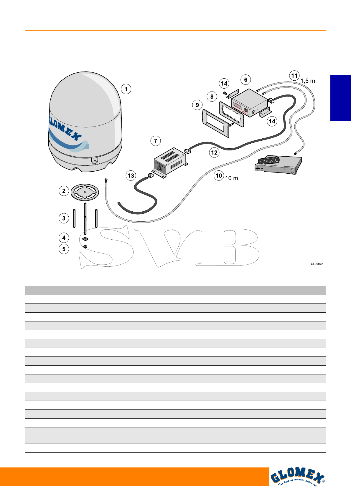
VENUS V9000 - SATURN V9100 - MARS V9801
VENUS SATURN MARS RHINE
ENGLISH
Satellite receiver
(not provided)
Fig. 1B
VENUS V9000/SATURN V9100/MARS V9801 Fig. 1B
Component GLOMEX code
Antenna unit V9000 (1) 3.010.0015
Antenna unit V9100 (1) 3.010.0016
Antenna unit V9801 (1) 3.010.0017
Base seal (2) 4.010.0415
M8 x 100 threaded bars (4 pcs) (3) 4.100.0118
Fastening reinforcements (4 pcs) (4) 4.020.0247
M8 self-locking nuts (4 pcs) (5) 4.100.0019
Control unit (6) 4.120.0042
Power supply for control unit (7) 4.120.0043
Vimar support for control unit fastening (8) 4.010.0153
Frame for built-in installation (9) 4.010.0154
10 m cable for antenna - control unit connection (10) V9139/10
1.5 m cable for line amplifier - decoder connection (11) V9143
Power supply cable for control unit - power supply (12) 4.070.0100
Connection cable for power supply - magneto-thermal switch on the on-board
panel (13)
Brackets for fastening the control unit on a horizontal surface (14) 4.020.0611
4.070.0101
www.glomex.it
51
Page 54
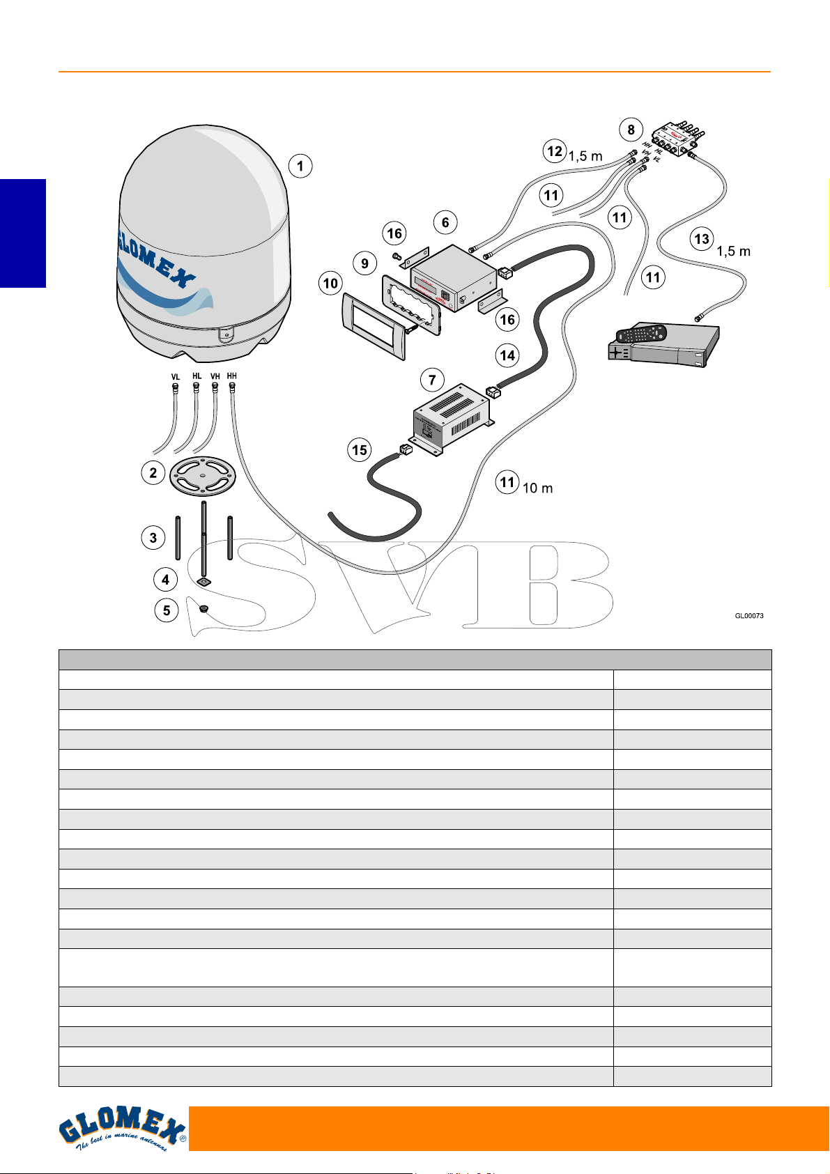
VENUS SATURN MARS RHINE
SATURN V9104 - MARS V9804 - SATURN V9104SKEW - MARS V9804SKEW
ENGLISH
Satellite receiver
(not provided)
Fig. 1C
SATURN V9104 - V9104 SKEW/MARS V9804 - V9804 SKEW Fig. 1C
Component GLOMEX code
Antenna unit V9104 (1) 3.010.0018
Antenna unit V9104 SKEW (1) 3.010.0019
Antenna unit V9804 (1) 3.010.0020
Antenna unit V9804 SKEW (1) 3.010.0021
Base seal (2) 4.010.0415
M8 x 100 threaded bars (4 pcs) (3) 4.100.0118
Fastening reinforcements (4 pcs) (4) 4.020.0247
M8 self-locking nuts (4 pcs) (5) 4.100.0019
Control unit (6) 4.120.0042
Power supply for control unit (7) 4.120.0043
Multiswitch (8) V9191
Vimar support for control unit fastening (9) 4.010.0153
Frame for built-in installation (10) 4.010.0154
10 m cables for antenna - control unit and antenna - multiswitch connection (11)
(4 pcs)
1.5 m cable for control unit - multiswitch connection (12) V9143
1.5 m cable for multiswitch - decoder connection (13) V9143
Power supply cable for control unit - power supply (14) 4.070.0100
Connection cable for power supply - magneto-thermal switch on the on-board panel (15) 4.070.0101
Brackets for fastening the control unit on a horizontal surface (16) 4.020.0611
V9139/10
52
www.glomex.it
Page 55
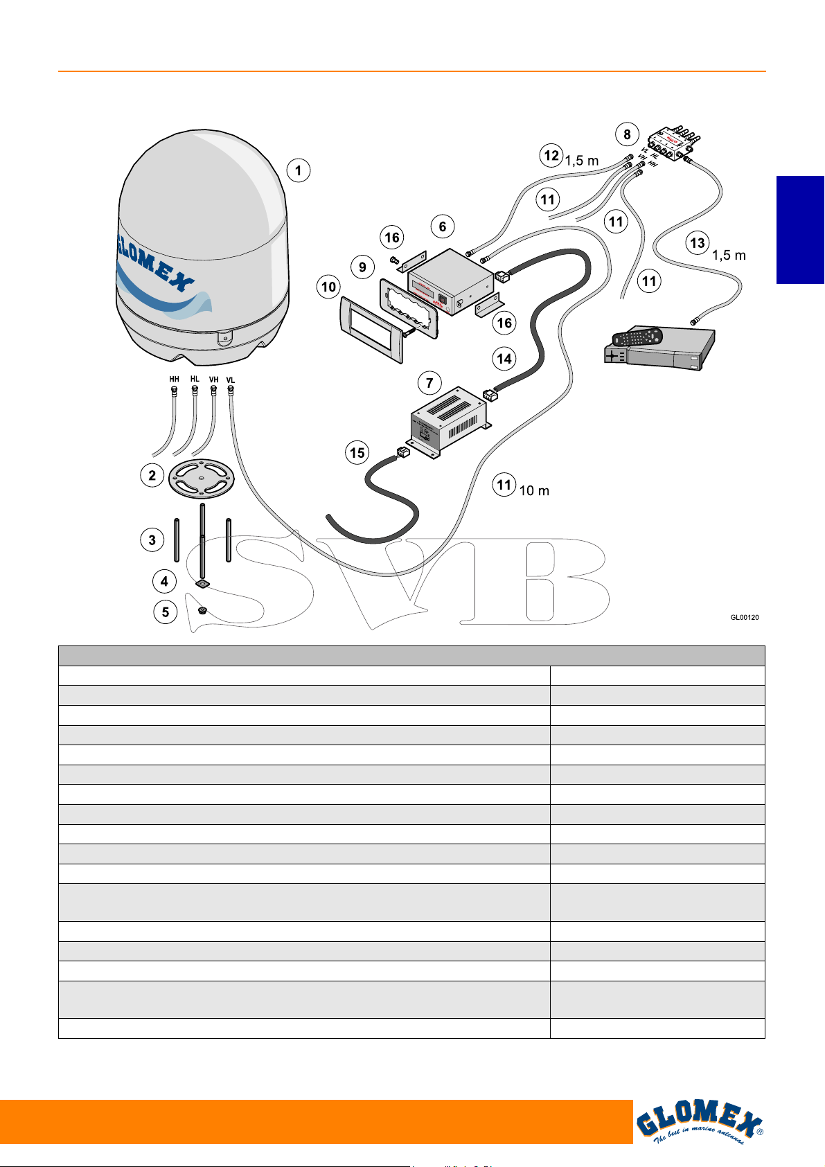
RHINE R9804
VENUS SATURN MARS RHINE
ENGLISH
Satellite receiver
(not provided)
Fig. 1D
RHINE R9804 Fig. 1D
Component GLOMEX code
Antenna unit R9804 (1) 3.010.0023
Base seal (2) 4.010.0415
M8 x 100 threaded bars (4 pcs) (3) 4.100.0118
Fastening reinforcements (4 pcs) (4) 4.020.0247
M8 self-locking nuts (4 pcs) (5) 4.100.0019
Control unit (6) 4.120.0042
Power supply for control unit (7) 4.120.0043
Multiswitch (8) V9191
Vimar support for control unit fastening (9) 4.010.0153
Frame for built-in installation (10) 4.010.0154
10 m cables for antenna - control unit and antenna - multiswitch
connection (11) (4 pcs)
1.5 m cable for control unit - multiswitch connection (12) V9143
1.5 m cable for multiswitch - decoder connection (13) V9143
Power supply cable for control unit - power supply (14) 4.070.0100
Connection cable for power supply - magneto-thermal switch on the on-
board panel (15)
Brackets for fastening the control unit on a horizontal surface (16) 4.020.0611
V9139/10
4.070.0101
www.glomex.it
53
Page 56
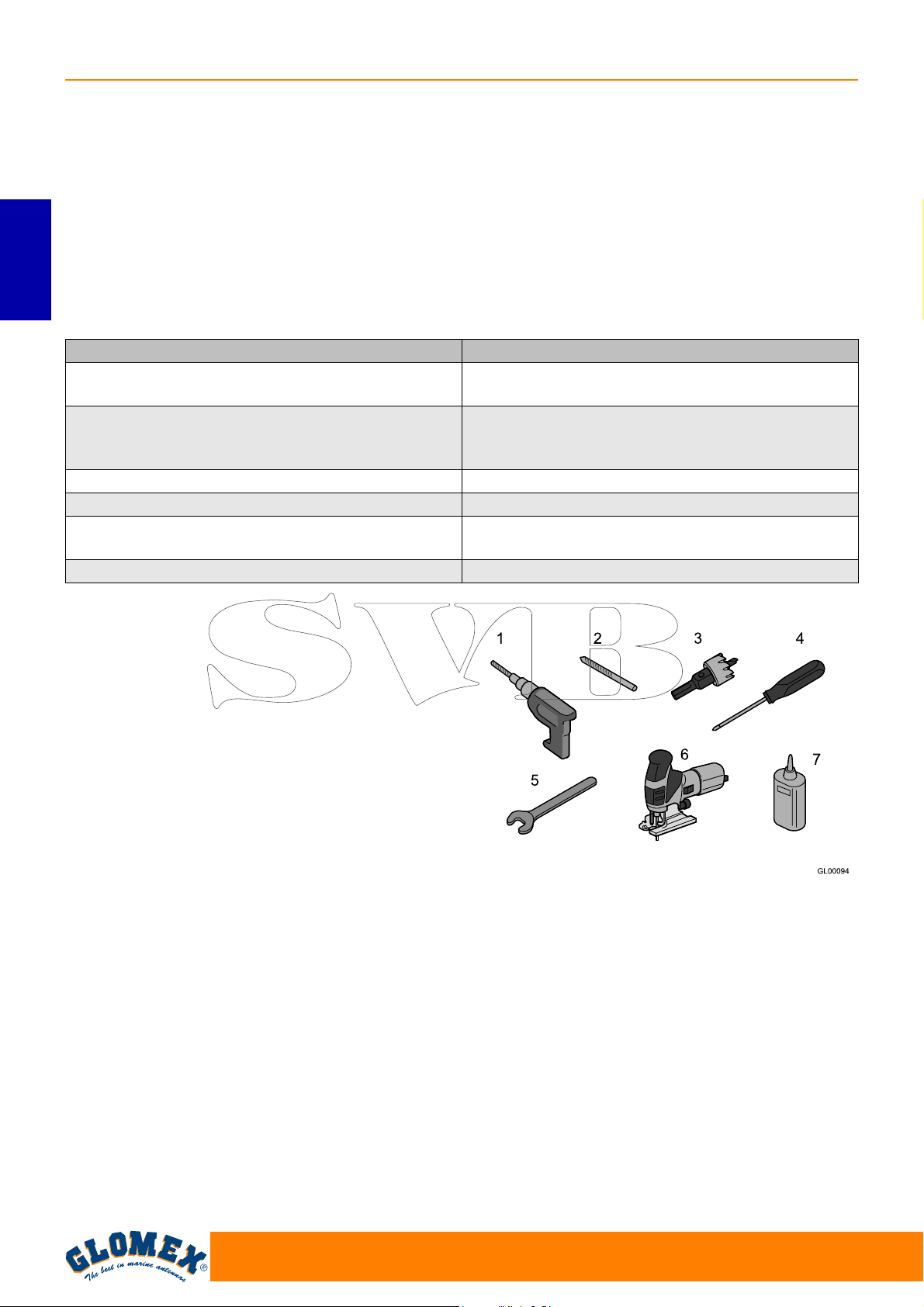
VENUS SATURN MARS RHINE
3.1 OPTIONAL ACCESSORIES (NOT
INCLUDED) TO USE GLOMEX
ANTENNAS
To be able to use your new GLOMEX satellite
antenna for boats, you will have to procure or buy
also:
- a TV set;
- a satellite receiver for channel selection.
ENGLISH
The table below lists all the GLOMEX optional
components, with relevant code.
Optional accessory GLOMEX code
Satellite decoder i-CAN 1110SV TIVÙSAT 230 VAC
- 12 VDC
XDome terrestrial digital - satellite HD combi
decoder (DVB-T + DVB-S + DVB-S2) compatible
with SKY ITALIA - 230 VAC
Stainless steel support 0°- 5° V9500
Twin radome V9... TWIN - R9804 TWIN
Radome painting - RAL colour chosen by the
customer
Line amplifier V9115
V9193
V9192
SATPAINT
4. NECESSARY TOOLS FOR ASSEMBLY (NOT PROVIDED)
Procure all tools and materials listed below. They
will be necessary to complete installation.
- Electric drill (1).
- 8.5 mm drill tip for radome assembly (2).
- 28 mm hollow mill for drilling the passage hole
for the antenna connector cable (3).
- Phillips screwdriver (with adequate dimensions
for control unit installation) (4).
- 11 mm wrench (for the installation of the coaxial
cable connectors) (5).
- Reciprocating saw (to create the compartment
in case of wall built-in installation of the control
unit; use the template provided on page 67) (6).
- LOCTITE ® 638 (7)
Fig. 2
54
www.glomex.it
Page 57
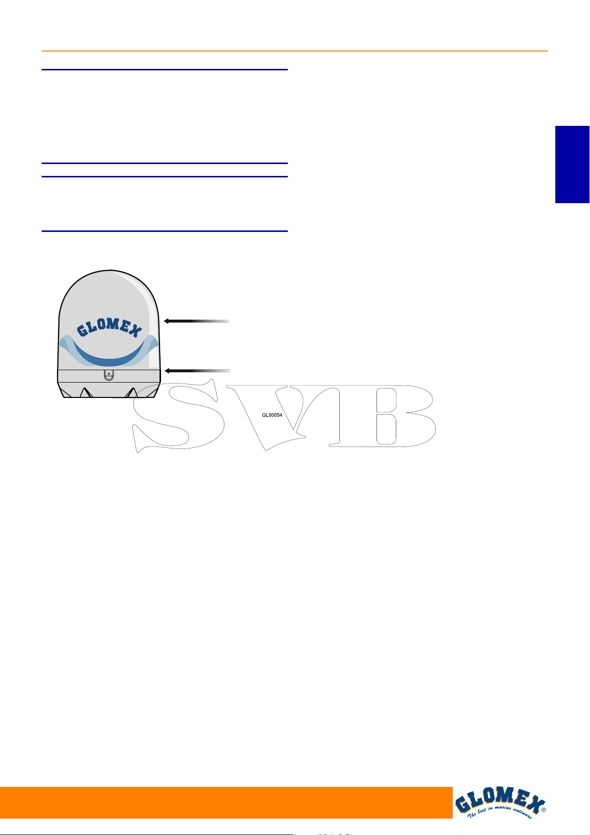
VENUS SATURN MARS RHINE
S
Plan the whole installation before proceeding!
Please consider the lay-out of the various components, the distance between them, the length of the
various cables and the accessibility to the equipment once it is installed.
S
Always lift the antenna from the lower radome and
never from the upper radome or any part inside it.
WARNING
WARNING
Upper radome
Lower radome
ENGLISH
Fig. 3
www.glomex.it
55
Page 58
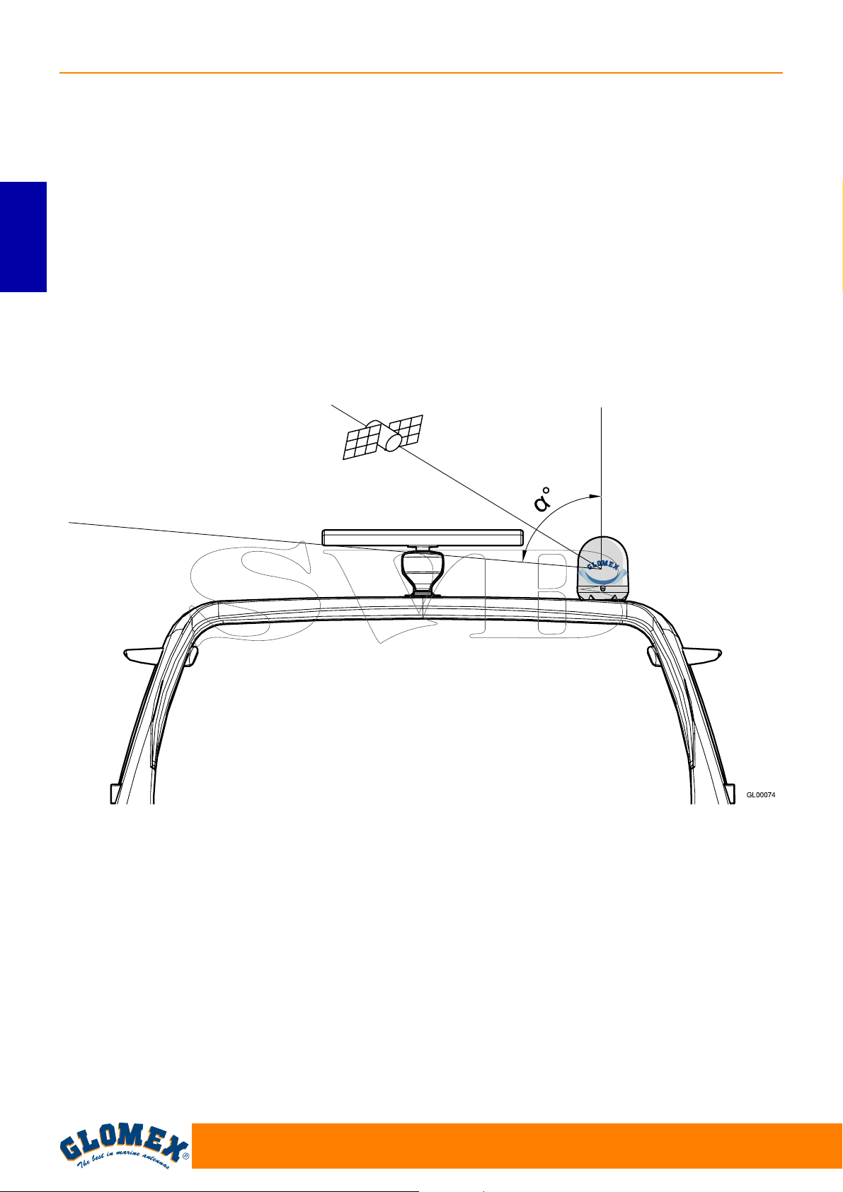
VENUS SATURN MARS RHINE
5. INSTALLATION
Before proceeding with the installation, please
respect the following guidelines:
- please remember that the best position for the
satellite TV antenna is in the middle of the boat,
in the lowest possible position.
- minimize obstruction. The antenna requires a
clear view of the sky in order to receive satellite
TV signals. The fewer the obstacles, the better
ENGLISH
the system operation.
Any foreign body (flags, antennas, radar antennas, sailboat masts, cranes, bridges, etc.)
between the antenna and the satellite obstructs
the signal and prevents correct receipt.
- make sure that the mounting surface is wide
enough for the antenna base to be installed.
Obstructed signal!
- make sure that the mounting surface is resistant
and rigid enough to support the weight of the
antenna and the vibrations which could occur.
- do not install the antenna near speakers or magnetic sources. In case it is not possible, it is necessary to compensate the magnetic source,
paying attention not to interfere with the on-board
compass.
- the antenna requires a lifting angle
and 90° to receive satellite signals (Fig. 4).
α between 5°
Fig. 4
TV antenna
Roll-bar
α = lifting angle
56
www.glomex.it
Page 59
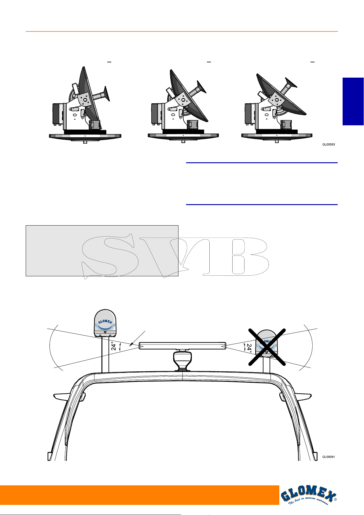
VENUS SATURN MARS RHINE
Typical antenna lifting
NORTHERN EUROPE (~ 15°) CENTRAL EUROPE (~ 35°) SOUTHERN EUROPE (~ 50°)
Fig. 5
- please also consider the position of the antenna
with respect to the position of all various attachments or wiring harnesses inside the boat.
- the control unit should be mounted in a convenient position for the adjusting operations. It
should be near the receiver/TV-set unit, so that
the TV screen may be watched while carrying out
the operations on the control unit.
S
The radio frequency beam transmitted by the radar
may damage the inner electronics of the antenna,
especially the LNB.
WARNING
ENGLISH
We recommend not to install the antenna at the
same level of the radar, as the radar’s energy
could damage the antenna. The antenna should
be positioned at a distance of at least 1.5 m from
the other transmitting antennas (VHF, radar) (Fig.
6).
OK NO
Typical radar vertical
irradiation angle
Fig. 6
www.glomex.it
57
Page 60
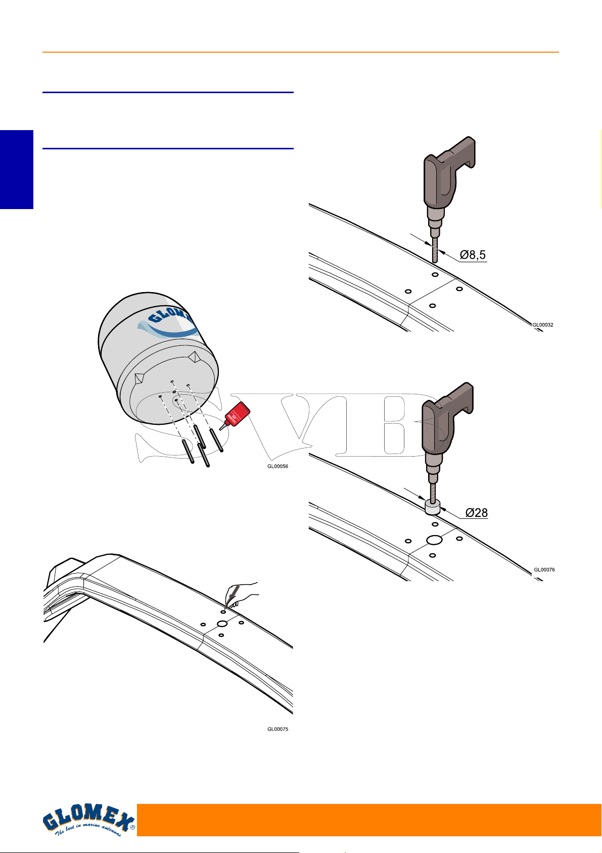
VENUS SATURN MARS RHINE
6. ASSEMBLY
S
While installing the antenna, wear the appropriate
safety equipment for the job to be carried out.
1. First of all, make sure you have chosen a cor-
rect position to install the antenna (see section
ENGLISH
5: “Installation”).
2. Remove the antenna from the packaging box.
Remove the screws from the lower radome.
3. Underneath the base of the antenna, insert the
4 M8 threaded bars and use a liquid thread
locking product (Loctite®638).
DANGER
5. Drill the 4 holes for the passage of the threaded
bars by means of an electric drill and a 8.5 mm
drill tip on the supporting surface.
Fig. 7
4. Use cutting template 6.1 on page 66 and use a
felt-tip pen to mark the holes for the threaded
bars and cable passage.
Fig. 9
6. Drill the hole for cable passage by means of an
electric drill and a 28 mm hollow mill.
Fig. 10
7. Position the rubber seal so that the holes
match.
Fig. 8
58
www.glomex.it
Page 61
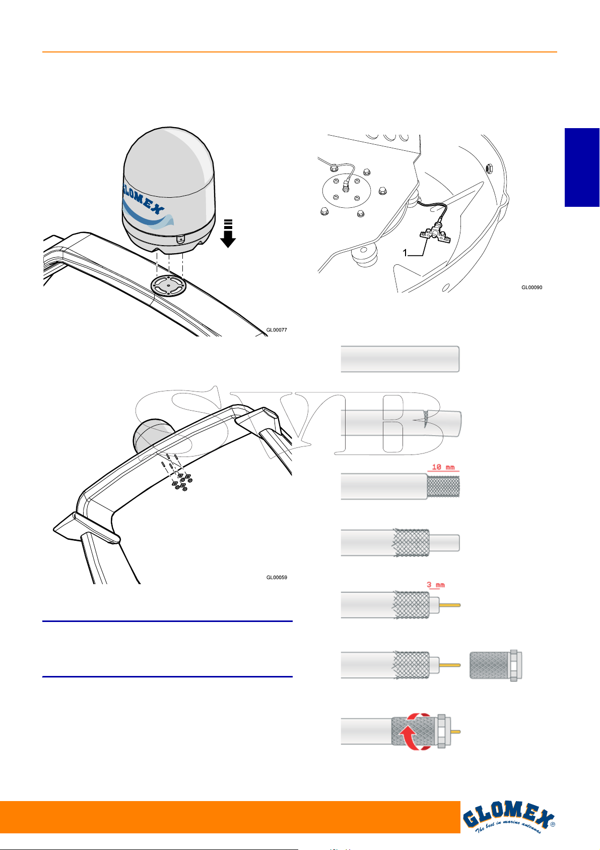
VENUS SATURN MARS RHINE
8. Position the antenna onto the seal, inserting the
4 threaded bars through the holes, and pay
attention to direct the orientation symbol of the
antenna towards the bow.
Fig. 11
9. Install the fastening reinforcements onto the
threaded bars and screw in the M8 self-locking
nuts.
13. To connect the coaxial cable it is necessary to
remove the upper radome and to connect it to
the connector (1) found on the lower radome,
trying to give it a path that follows the curvature
of the radome.
ENGLISH
Fig. 13
14. Should it be necessary to shorten the cable,
please refer to the instructions given in Fig. 14.
Fig. 12
10. Completely tighten.
S
GLOMEX declines any liability for an incorrect
mounting of the radome on the boat.
11. Have the 10 m cable pass through the previously drilled hole (V9000, V9100, V9801).
12. Have the four 10 m cables pass through the
previously drilled hole (V9104, V9104SKEW,
V9804, V9804SKEW, R9804).
WARNING
www.glomex.it
GL00095
Fig. 14
59
Page 62
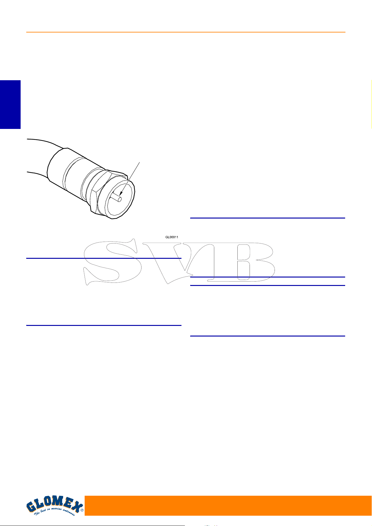
VENUS SATURN MARS RHINE
15. Make sure that the cable core is correctly
inserted in the central hole of the female connector on the antenna.
Manually screw in the ring nut of connector F.
Once the ring nut has been manually screwed
in, tighten by ¼ turn by means of a 11 mm
wrench.
16. Remove the two safety straps found on the azimuth and lifting gears.
ENGLISH
Central coaxial
cable conductor
2. Determine the correct position for the power
supply:
- it must be close to the control unit;
- it must be reached by the (red - black) cable
coming from the batteries or from the onboard panel;
- it must be positioned in a dry and ventilated
area (maximum operating temperature
45 °C).
3. Connect the coaxial cable of the antenna (previously installed) to the ANTENNA IN input on
the control unit and a coaxial cable between the
RECEIVER OUT output on the control unit and
the decoder.
Make sure that the cable cores are correctly
inserted in the central holes of the relevant
female connectors on the control unit.
Manually screw in the ring nuts of connectors F.
Once the ring nuts have been manually
screwed in, tighten by ¼ turn by means of a 11
mm wrench.
Fig. 15
S
For a correct assembly, respect the installation
direction indicated in Fig. 11.
A different installation from the recommended one
could cause an incorrect operation of the antenna
due to the risk of water penetration into the
radome.
Operations to be carried out inside the boat.
1. Determine the correct position for the control
unit:
- it must be positioned near the satellite
receiver, as the provided coaxial cable is
1.5 m long;
- it must be reached by the power supply cable
coming from the power supply;
- it must be reached by the coaxial cable com-
ing from the antenna (10 m long);
- it must be positioned in a dry and ventilated
area (maximum operating temperature
45° C).
WARNING
S
The inversion of the two cables jeopardizes the
operation of the equipment. Make sure you have
correctly installed the coaxial cables. In case of
damage, GLOMEX will not be directly liable for the
damage suffered by the receiver.
S
Antennas V9000, V9100 and V9801 are designed
to operate with a single decoder; therefore, do not
install signal splitters upstream or downstream the
control unit.
WARNING
WARNING
60
www.glomex.it
Page 63
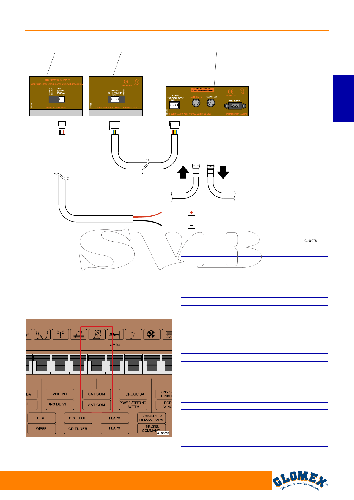
VENUS SATURN MARS RHINE
Power supply
Backside of the power
supply
From the antenna
Backside of the control unit
ENGLISH
To the decoder (V9000-V9100-V9801)
To the multiswitch (V9104-V9804) HH
To the multiswitch (R9804) VL
Red
10 ÷ 30 VDC
Black
Fig. 16
4. Connect the power supply cable (10-30 VDC)
to a free switch for the on-board electronic
devices (min. 5A): connect the positive terminal
to the red cable and the negative terminal to the
black cable. The power supply line must have
cables with a minimum cross section of
2
2.5 mm
longer cables.
Fig. 17
with a length up to 4 m, of 4 mm2 for
S
Do not use power supply from secondary circuits.
This could jeopardize the operation of the equipment.
S
In order to prevent that current leakage or charge
build-up may damage the electronic components of
the antenna, make sure there is an efficient
grounding system.
S
Pay attention not to bend the coaxial cables at a
right angle; the bending angle must always be
higher than 120°.
NOTE (applies to V9000): in case a cable longer
than 10 m should be necessary for connecting the
control unit to the satellite receiver, we recommend
installing line amplifier V9115 between them.
WARNING
WARNING
WARNING
www.glomex.it
61
Page 64
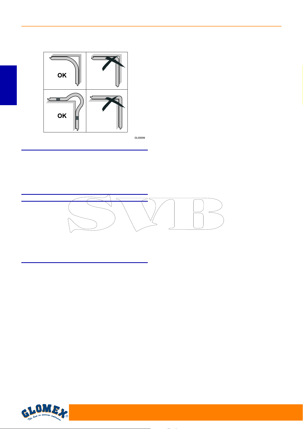
VENUS SATURN MARS RHINE
ENGLISH
Fig. 18
NOTE: Do not cut the connectors of the coaxial
cables (the operation would not be guaranteed any
more) and always use the original GLOMEX cables
supplied, even with inappropriate dimensions (too
long). Do not use different cables, as it would
jeopardize the operation of the equipment.
S
If the control unit shows the error message ERR1,
there is no communication between the antenna
and the control unit.
It is therefore necessary to check that the connection cable between antenna and control unit is correctly fastened and is not interrupted or shortcircuited.
WARNING
62
www.glomex.it
Page 65
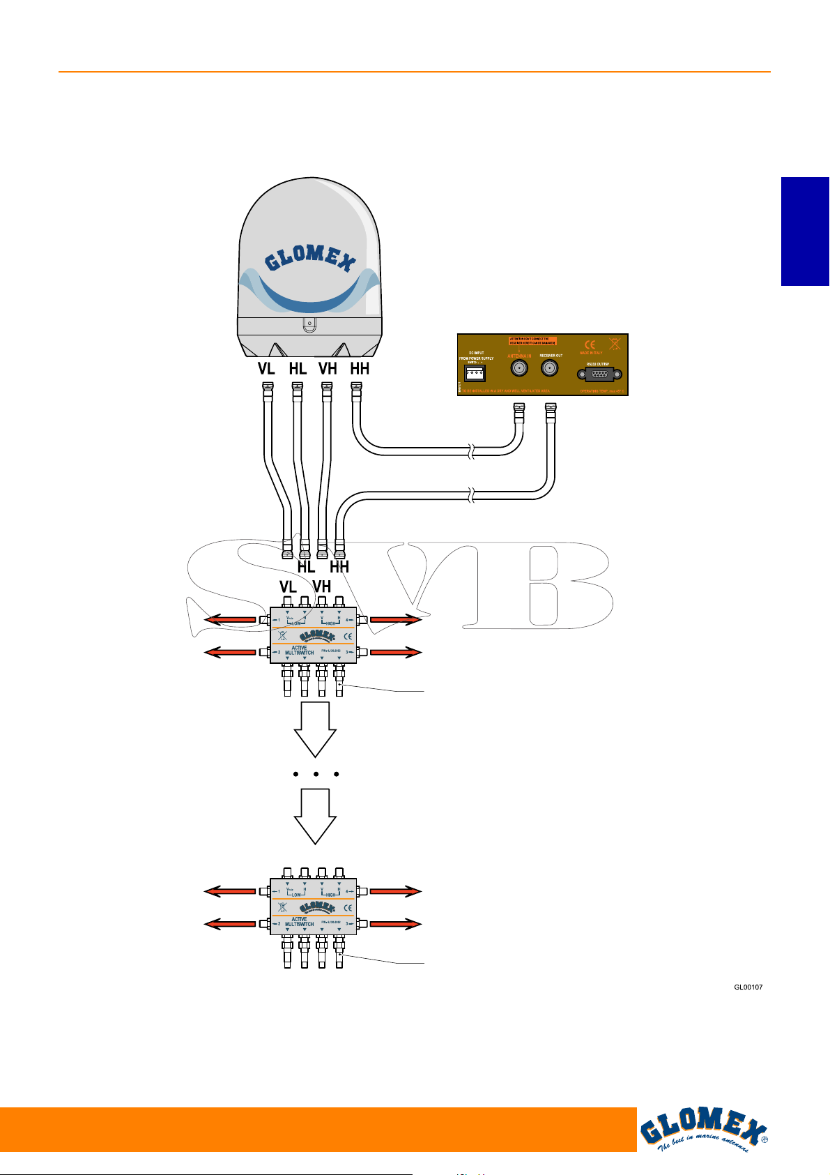
5. For models V9104, V9104SKEW, V9804 and
V9804SKEW which provide for the presence of
the multiswitch, connect the cables by following
the indications given in Fig. 19.
VENUS SATURN MARS RHINE
ENGLISH
Backside of the control units
Fig. 19
Receiver
Receiver
Receiver
Receiver
Receiver
Receiver
Isolated 75 ohm charge or maximum another
3 multiswitches and, on the last one, the
isolated 75 ohm charge.
Receiver
Receiver
Isolated 75 ohm charge
www.glomex.it
63
Page 66
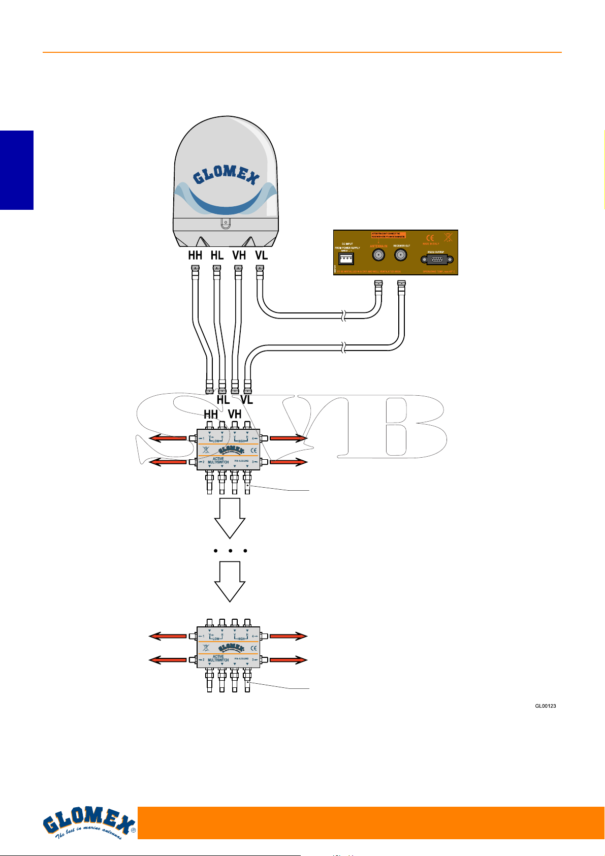
VENUS SATURN MARS RHINE
6. For model R9804 connect the cables by following the indications given in Fig. 20.
ENGLISH
Backside of the control units
Fig. 20
Receiver
Receiver
Receiver
Receiver
Receiver
Receiver
Isolated 75 ohm charge or maximum another
3 multiswitches and, on the last one, the
isolated 75 ohm charge.
Receiver
Receiver
Isolated 75 ohm charge
64
www.glomex.it
Page 67
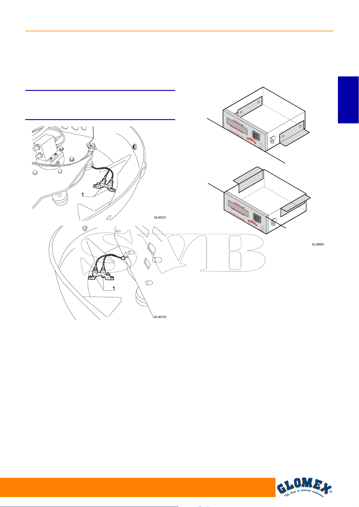
VENUS SATURN MARS RHINE
To connect the coaxial cables to VL, HL, VH and
HH sockets of the coaxial rotating joint it is necessary to remove the upper radome and to connect
the various cables to the connectors (1) available
inside the lower radome, trying to give the cables a
path that follows the curvature of the radome.
NOTE: for some models, there is a single bracket
with 4 connections instead of 2 brackets with 2
connections each.
8. Connect the cables to the line amplifier (is available), to the multiswitch (if available), to the
receiver(s) (not included), as indicated in Fig. 1,
Fig. 16, Fig. 19.
ENGLISH
Fig. 21
7. The control unit may be fastened to a vertical
wall by means of the Vimar
®
in-built covering
frame provided together with the antenna. In
this case, drill a hole with a reciprocating saw,
using the cutting template in Fig. 23.
The control unit may be fastened also to a horizontal surface or to the roof. In this case, it is
necessary to use the 2 L-shaped brackets provided together with the antenna and fasten
them as indicated in Fig. 22.
Fig. 22
www.glomex.it
65
Page 68
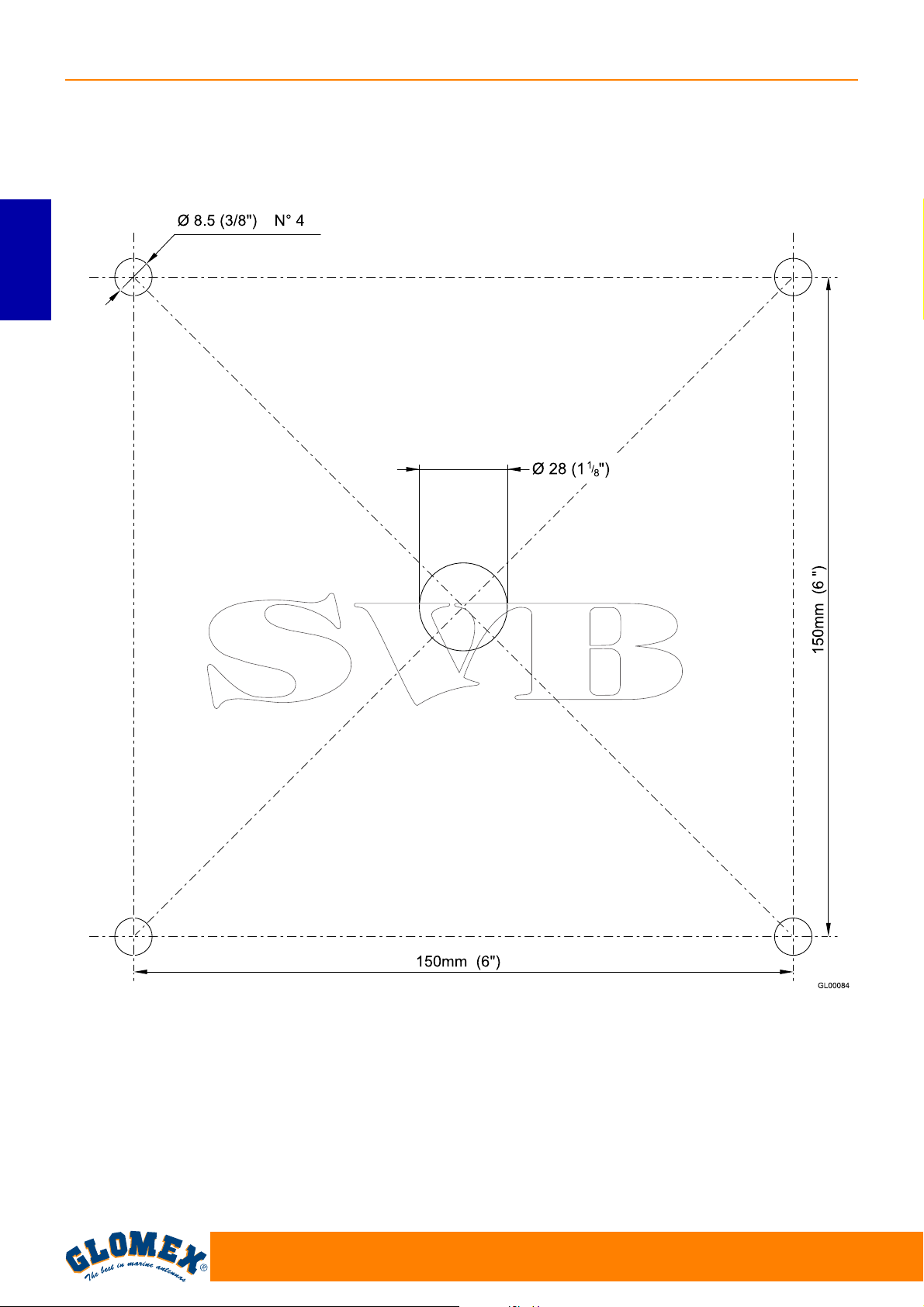
VENUS SATURN MARS RHINE
6.1 LOWER RADOME CUTTING TEMPLATE
ENGLISH
Fig. 23
66
www.glomex.it
Page 69
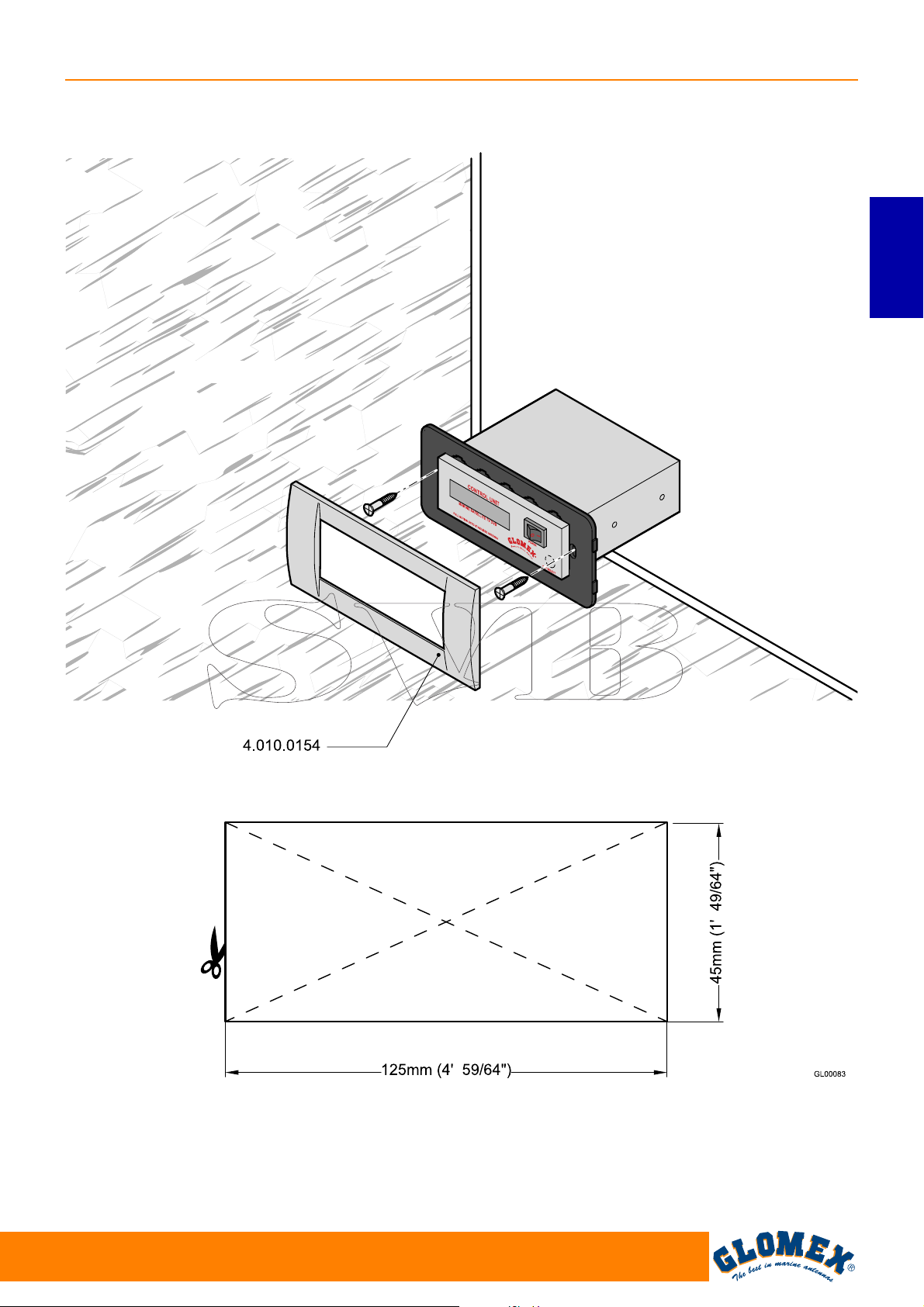
VENUS SATURN MARS RHINE
6.2 CONTROL UNIT CUTTING TEMPLATE FOR INSTALLATION ON A VERTICAL WALL
ENGLISH
Fig. 24
www.glomex.it
67
Page 70
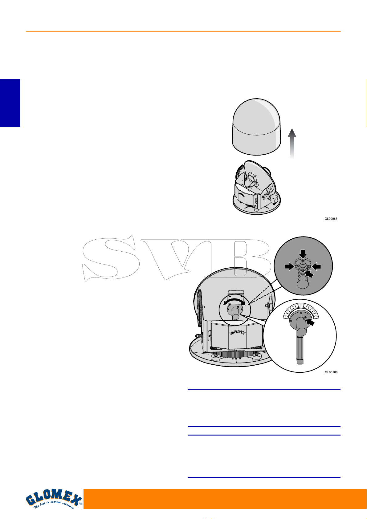
VENUS SATURN MARS RHINE
6.3 SKEW CALIBRATION (MANUAL)
Satellites can transmit in linear (Europe) or circular
(USA) polarisation. GLOMEX antennas are
designed to operate with a linear or circular polarisation according to the installed LNB, depending
on the satellite whose transmission you want to
receive and on where you are positioned.
Circular polarisation does not require any calibration for the optimization of the received signal.
ENGLISH
On the contrary, LNB operating with linear polarisation need calibrating upon installation, in order to
optimize the alignment of the LNB with the satellite
whose transmission you want to receive.
When you are at the same longitude of the satellite,
its horizontal and vertical signals are aligned with
the horizon. When the satellite is east or west of
your position, the signal of the satellite will appear
as clockwise or counterclockwise shifted. Both the
horizontal and the vertical signal will be shifted by
the same angle, and therefore they will always be
perpendicular to each other.
The degree of rotation will depend on the distance
to the east or to the west between the position of
the antenna and the position of the satellite, and on
your distance from the equator.
Once you move to an area with a longitude more
than +/- 10° from the previous position, the LNB
must be manually adjusted in order to obtain the
best possible signal.
Antennas are delivered with the LNB optimized for
an area with longitude 12° East while receiving satellite 13° East.
Calibration does not need to be changed any
more if the boat remains in the same area and
receives transmission from the same satellite.
Once the desired adjustment has been carried out,
tighten the screws, position the upper radome onto
its base again and tighten the fastening screws.
Fig. 25
4 outputs
1 output
For the adjustment of the LNB, proceed as follows:
- loosen the screws on the radome and remove the
upper radome from the base;
- for one-output models, loosen the screw fastening the LNB to the dish (see Fig. 26) and manually move the dish, using the parameter of signal
quality of the digital receiver in use as a reference
for correct calibration (please refer to the
receiver’s manual). Calibration does not need to
be changed any more if the boat remains in the
same area and receives transmission from the
same satellite.
- for 4-output models, loosen the four socket-head
screws on the front part of the dish and manually
move it, using the parameter of signal quality of
the digital receiver in use as a reference for correct calibration (please refer to the receiver’s
manual).
68
Fig. 26
NOTE: the operations described above are not to
be carried out in case of antennas with automatic
SKEW adjustment!
(V9104SKEW and V9804SKEW)
S
While adjusting the SKEW, please make sure not
to disconnect the two sensor cables fastened to the
LNB.
WARNING
www.glomex.it
Page 71
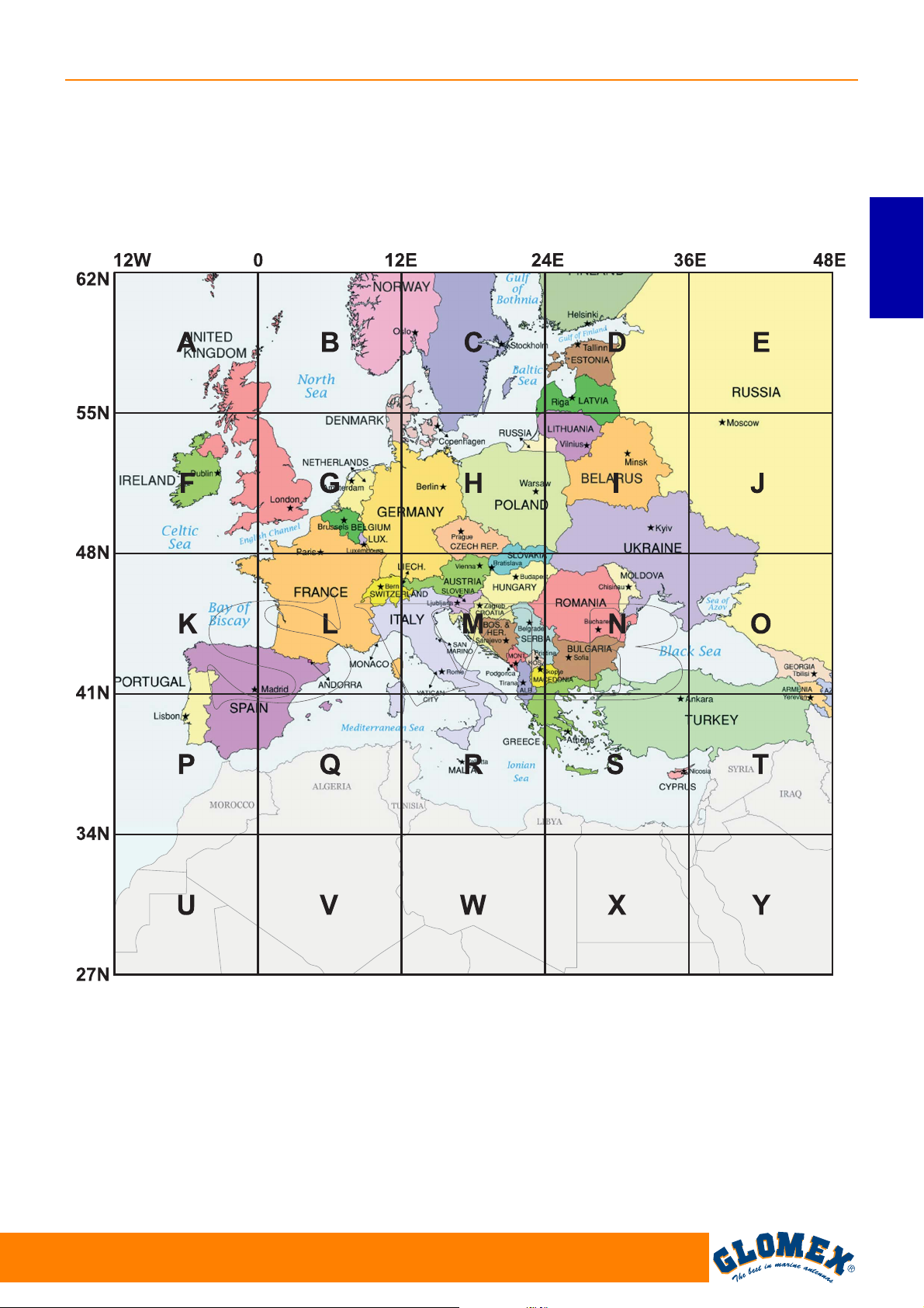
6.4 SKEW ADJUSTMENT GRID FOR
EUROPE
To determine the values for adjusting the LNB, it is
possible to use the grid below and the relevant
table.
VENUS SATURN MARS RHINE
ENGLISH
Fig. 27
We recommend obtaining the values for the adjustment by using the (free licence) software SMW
Link (distributed by SWEDISH MICROWAVE AB,
http://www.smw.se/smwlink.htm).
www.glomex.it
69
EGITTO
GIORDANIA
GL00096
Page 72
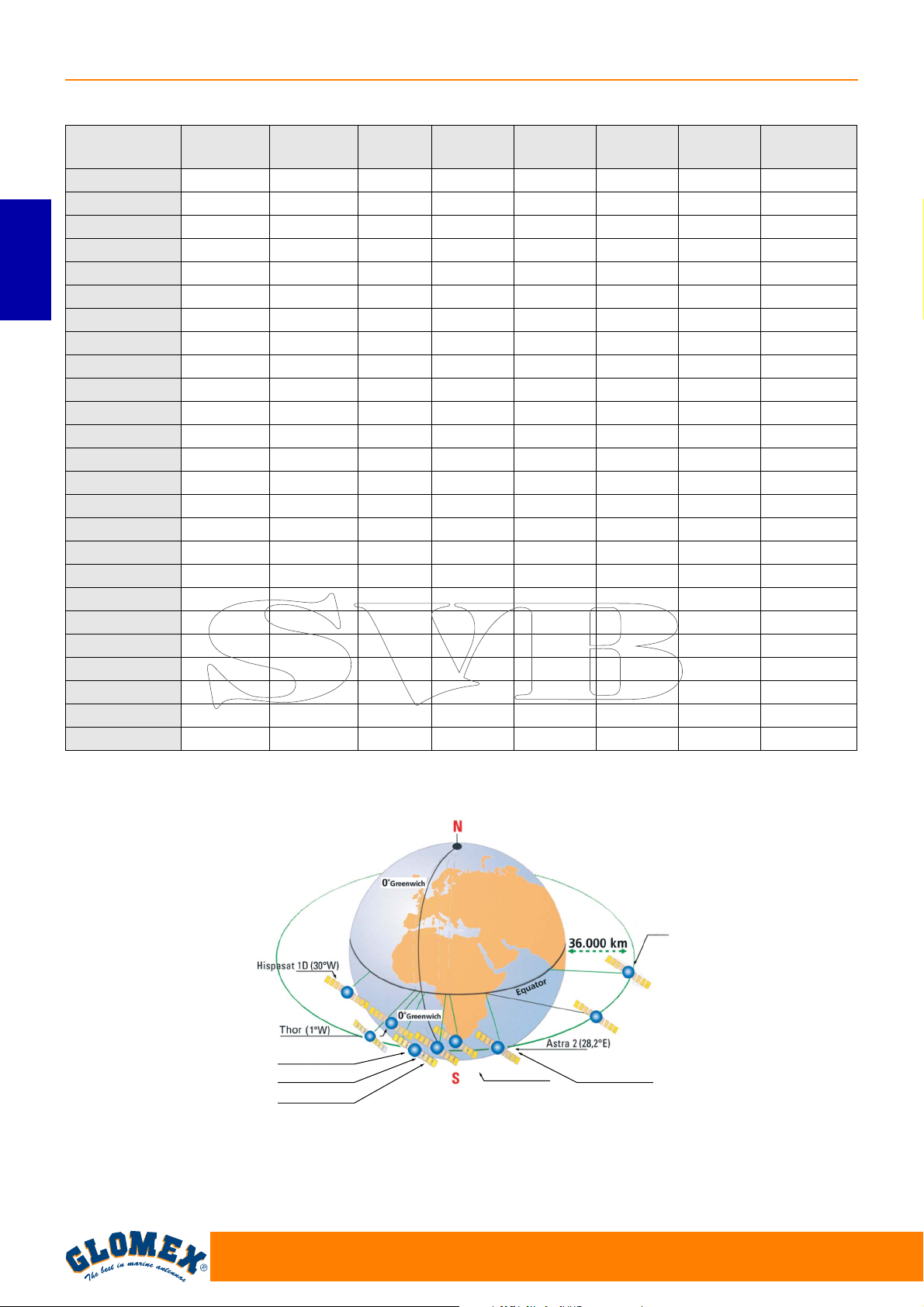
VENUS SATURN MARS RHINE
Grid position TURKSAT
42°E
ASTRA2
28.2°E
ASTRA3
23.5°E
ASTRA1
19.2°E
HOTBIRD
13.0°E
SIRIUS
4.8°E
THOR
1°W
A (6°W 58°N) -25° -19° -18° -14° -11° -6° -3° 14°
B (6°E 58°N) -20° -13° -12° -8° -4° 0° 4° 20°
C (18°E 58°N) -14° -6° -4° 0° 3° 8° 11° 24
D (30°E 58°N) -7° 1° 3° 6° 10° 14° 17° 28°
E (42°E 58°N) 0° 7° 10° 13° 16° 20° 23° 30°
ENGLISH
F (6°W 52°N) -30° -24° -21° -18° -14° -8° -3° 17°
G (6°E 52°N) -24° -16° -13° -10° -5° 0° 5° 24°
H (18°E 52°N) -17° -8° -5° 0° 3° 9° 14° 34°
I (30°E 52°N) -9° 1° 4° 8° 12° 18° 21° 36°
J (42°E 52°N) 0° 11° 12° 17° 20° 25° 28° 22°
K (6°W 45°N) -36° -29° -27° -23° -18° -10° -5° 30°
L (6°E 45°N) -30° -20° -20° -12° -7° 0° 6° 31°
M (18°E 45°N) -22° -9° -8° -1° 4° 12° 18° 36°
N (30°E 45°N) -11° 2° 5° 10° 16° 22° 27° 40°
O (42°E 45°N) 0° 13° 17° 21° 25° 31° 34° 43°
P (6°W 38°N) -43° -35° -36° -28° -22° -13° -6° 27°
Q (6°E 38°N) -37° -25° -23° -16° -8° 1° 8° 36°
R (18°E 38°N) -27° -12° -10° -1° 6° 16° 22° 43°
S (30°E 38°N) -15° 2° 8° 13° 20° 28° 33° 47°
T (42°E 38°N) 0° 17° 23° 26° 31° 37° 41° 50°
U (6°W 30°N) - -44° -43° -36° -28° -18° -8° 35°
V (6°E 30°N) - -33° -34° -21° -11° 1° 11° 45°
W (18°E 30°N) - -16° -11° -1° 8° 21° 29° 52°
X (30°E 30°N) - 3° 10° 18° 25° 36° 41° 56°
Y (42°E 30°N) - 22° 28° 34° 38° 46° 49° 58°
HISPASAT
30°W
Fig. 28
Sirius 4 (5°E)
Eurobird (9°E)
Hot-Bird (13°E)
70
Astra 1 (19,2°E)
Turksat (42°E)
Astra 3 (23,5°E)
GL00069
www.glomex.it
Page 73
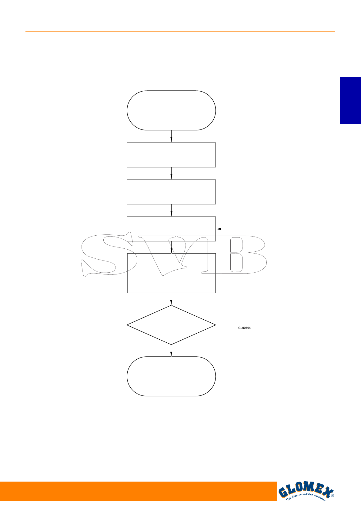
7. USE
Flow chart
POWER ON KEY I
SIGNAL SEARCH
CALIBRATION
SOUTH SEARCH
VENUS SATURN MARS RHINE
ENGLISH
SATELLITE SEARCH
SATELLITE FOUND
SATELLITE CHECK AND
IDENTIFICATION
IS IT THE SELECTED
SATELLITE?
YES
SATELLITE OK
NO
Fig. 29
www.glomex.it
71
Page 74
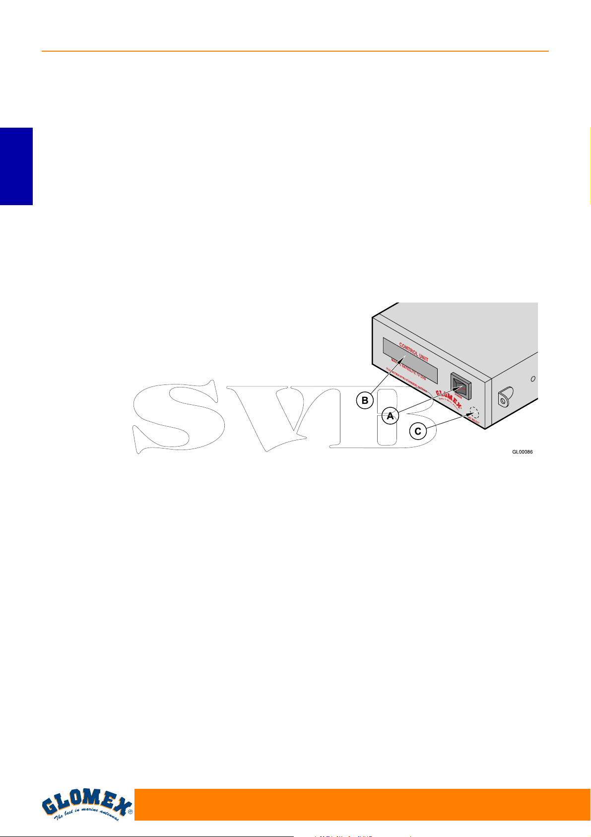
VENUS SATURN MARS RHINE
1. Make sure that the antenna has a clear view of
the sky in order to receive satellite signals.
2. Turn on the receiver and the TV set. For details
about the use of the receiver and the TV set,
please refer to the relevant user manuals provided by the manufacturers.
3. To turn on the control unit, position the key (A)
to I: the antenna automatically communicates to
the control unit when it is ready and starts
ENGLISH
searching for the selected satellite taking min.
20 seconds up to a max. of 2 minutes, according to the boat’s movement.
4. LANGUAGE SELECTION: upon start-up, while
GLOMEX appears on the display, it is possible
to select the desired language (among Italian,
English, French, Spanish and German) by
repeatedly pressing key (C). To confirm selection, just turn off and on again the control unit
by means of key (A).
5. SELECTION OF THE SATELLITE TO BE
SEARCHED: repeatedly press key (C) for satellite selection, until the alphanumeric display in
its first line (B1) corresponds to the desired
choice.
The following satellites are the ones which can
be received with the device:
- ASTRA2 28.2°E
- ASTRA3 23.5°E
- ASTRA1 19.2°E
-HOTBIRD 13°E
- EUROBIRD 9°E
- SIRIUS 4.8°E
- THOR 1°W
- HISPASAT 30°W
After selecting the desired satellite, the antenna
immediately starts searching for the signal, indicating it in the second line of the display (B2).
6. SATELLITE SIGNAL SEARCH AND
TRACKING: when the antenna has found the
satellite signal, this is verified and, in case of
success, the display shows “sat ok” (B2).
Sometimes it may happen that an antenna first
receives a different satellite from the selected
one (depending on position, transmitted signal
strength and weather conditions). In this case,
the NIT system check is negative and the
antenna immediately starts searching for the
selected satellite, taking into account the position of the satellite just found. The control unit
saves the last satellite position selected on it
and, the next time it is turned on, it starts
searching for this last satellite position. When
the antenna is tracking, you can watch TV pro-
grammes and listen to the RADIO using a
receiver and a TV set (not provided).
7. ENERGY SAVING FUNCTION: when the boat
is moored and the movements are minimal, you
can activate the energy saving function that will
not only minimize electric consumption, but also
eliminate any noise coming from the antenna.
To enable this function, press key (C) once for
satellite selection (the display indicates the status - enabled or disabled). To change status,
press key (C) again. When the function is enabled, after about 2 minutes that the boat did not
move, the antenna stops in the position where
signal reception from the satellite is maximum.
A level decrease of the received signal or a total
shift of the boat of 6° in two minutes “wake the
antenna up” in order that it recovers the maximum receivable signal level.
A. Power on key
B. Two-line alphabetic display:
• B1 (first line): name of the satellite to be
received
• B2 (second line): running function
C. Key for satellite selection and activation/
deactivation of energy saving system.
Fig. 30
72
www.glomex.it
Page 75
CAPTION OF CONTROL UNIT FUNCTIONS
Start-up: when turning on the control unit, the dis-
play shows
‘ GLOMEX MK2+ DVBS ’
‘ ANTENNA VX.XXX ’
VX.XXX = SW VERSION
ANTENNA INIT: in this phase, the antenna posi-
tions itself for calibration;
CALIBRATION: calibration phase of the gyro-
scopes;
SOUTH SEARCH: rotation of the azimuth axis
which positions the antenna southbound;
SAT SEARCH: satellite search; unless the user
intervenes, the antenna automatically starts
searching for the last satellite received;
FOUND SAT: writing that appears on the display
when the antenna finds a satellite signal before the
NIT system check is run.
LOST SIGNAL: it appears in case the signal is lost;
ANT. STANDBY: it appears when the antenna
manages to receive the satellite signal and the boat
remains motionless for a certain period of time. In
this situation, the antenna stops on the maximum
value of the received signal, reducing operating
noise and energy consumption;
NEXT SAT SEARCH: message displayed when
the antenna passes from one satellite to another,
when the first satellite received does not match the
one selected;
SAT VERIFICATION: message that appears when
the satellite is received during the NIT system verification phase;
WARNING ERR 1: there is no communication
between the antenna and the control unit.
SAT OK: it indicates that the selected satellite has
been correctly hooked up and verified.
VENUS SATURN MARS RHINE
ENGLISH
www.glomex.it
73
Page 76
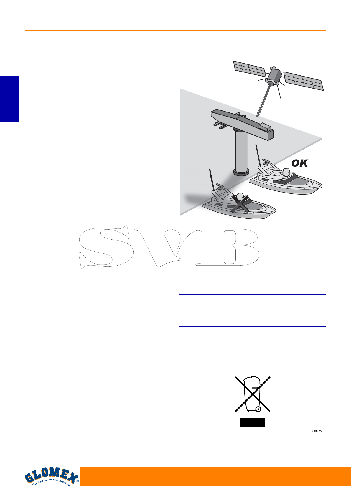
VENUS SATURN MARS RHINE
8. TIPS FOR CORRECT USAGE
GLOMEX recommends observing the following
indications for a correct use of the equipment.
- The receiver must be activated before receiving
the satellite programmes.
- Keep the radome always mounted on the
antenna. Its task is to protect all inner (fixed and
moving) parts from wind, rain and dust.
- Do not lean against and/or sit on the antenna!
ENGLISH
- Pay attention not to spill liquids of any kind into
the antenna.
- The radome should be cleaned periodically.
Dust or dirt accumulated on the radome could
affect the satellite signal receipt. Clean the
radome with a cloth damped with water. DO
NOT USE BRUSHES, ABRASIVE PRODUCTS,
DETERGENTS OR ALCOHOL-BASED LIQUIDS.
- Do not paint the surface of the radome! This
would negatively affect signal receipt.
- The antenna requires a clear view of the sky to
receive satellite signals. Possible very common
signal obstructions include masts of other boats,
bridges, on-board equipment, etc. GLOMEX
antennas also do not operate inside storage
areas.
GL00045
Fig. 31
- Heavy rain or snow could temporarily interrupt
signal receipt from the satellite.
- The boat must be within the coverage area of
the selected satellite to receive the desired signal. Please refer to the satellite coverage footprints on page 76.
S
Bad weather conditions affect the quality of the signal and reduce image quality!
- At the end of its life, do not scatter the antenna
or its components into the environment, but take
advantage of specialized waste disposal agencies.
WARNING
74
Fig. 32
www.glomex.it
Page 77
8.1 FOOTPRINTS: SATELLITE
TRANSMISSION AREAS
Satellite television is one of the few means which
allow receiving information in any part of the world
within the coverage area of the satellite you wish to
receive.
The signal transmitted by the satellite generally has
a wide coverage area, as shown in the purely indicative footprints on the following page, and thus
guarantees you can watch the same TV programmes in various areas.
However, it is important to remember that ground
obstacles are the main causes of satellite antenna
malfunction.
Ground obstacles include all bodies which could be
located between satellite and antenna, such as
masts of other boats, bridges, on-board equipment,
etc.
The signal transmitted by the satellite is also
affected by weather conditions (storm clouds or ice
clouds).
The footprints show the satellite coverage areas on
the Earth by using the GLOMEX satellite antennas.
VENUS SATURN MARS RHINE
ENGLISH
S
In case of bad weather, signals will be weaker;
therefore, the image quality could be reduced, up
to completely fading away. It is also very important
to make sure, upon purchase, that the dimensions
of the satellite antenna are the most appropriate
ones to receive the signal in the areas where you
spend your holiday. Footprints are indicative and
referred to the satellite with the strongest E.I.R.P.
(Equivalent Isotropic Radiated Power).
WARNING
www.glomex.it
75
Page 78
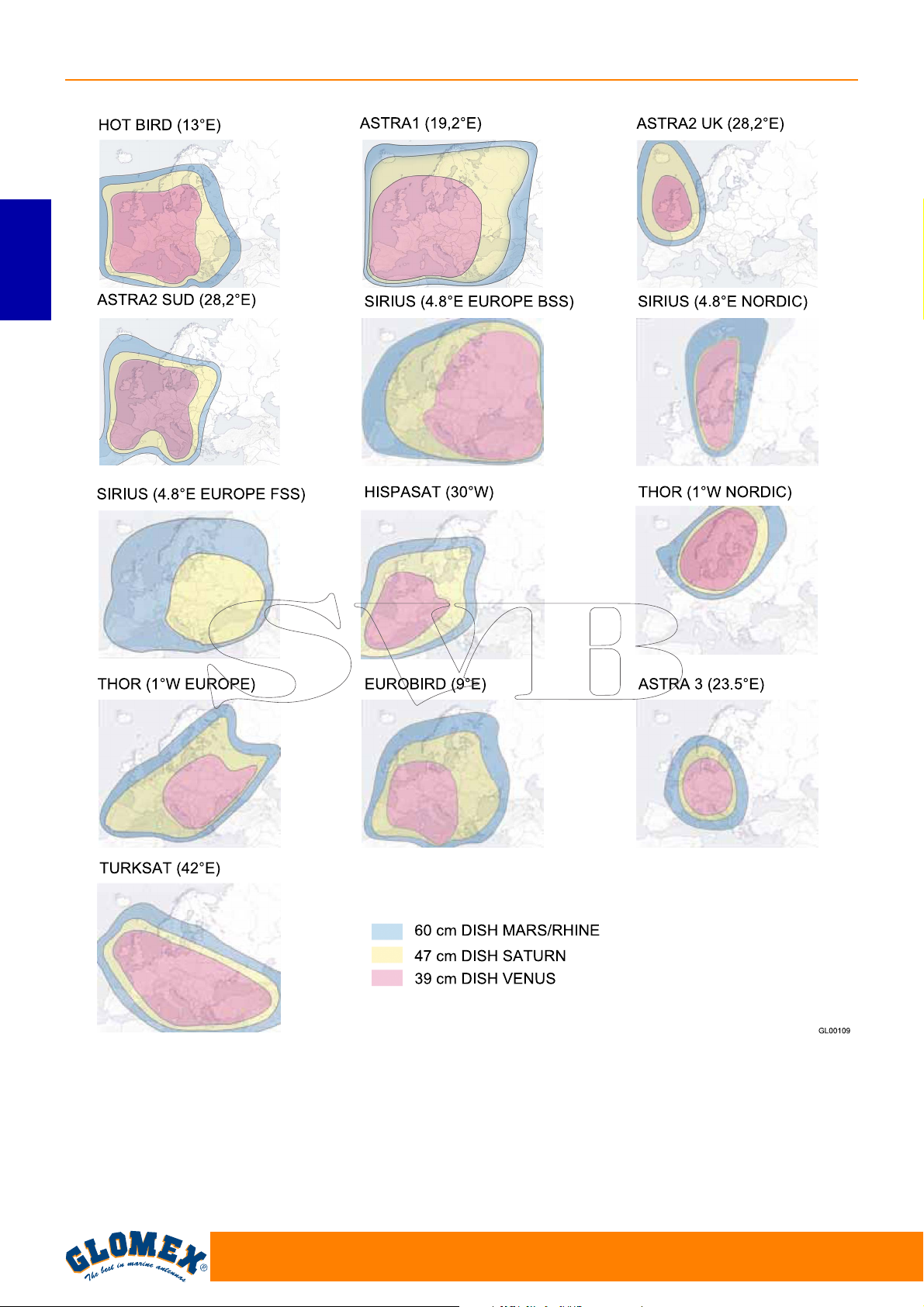
VENUS SATURN MARS RHINE
ENGLISH
Fig. 33
76
www.glomex.it
Page 79
9. MAINTENANCE
VENUS SATURN MARS RHINE
9.1 PREVENTIVE MAINTENANCE
GLOMEX antennas require minimum preventive
maintenance.
Observing the following instructions is sufficient to
maintain a high equipment performance.
Monthly checks
- Wash the radome surface with a cloth damped
with fresh water; do not direct pressurized water
jets onto the radome.
S
Do not use brushes, abrasive products, detergents
or alcohol-based liquids.
Yearly checks
- Check the outer conditions of the radome. Clean
from dust and dirt if necessary.
Checks before any long cruise
- Check that the antenna is correctly fastened.
WARNING
Should you have problems with the operation or in
case you need technical support, first of all contact
the authorized Retailer. Keep at hand the serial
number of your antenna (on page 2 in this manual)
and a list with the failure symptoms. Should no
Retailer be available, contact the GLOMEX Service
Centre (see section “Technical Support”).
S
You will be asked the serial number of your
antenna during any service or troubleshooting
phone call. The serial number is found on page 2 of
the user manual of your antenna (see page 47 for
serial number indications).
S
Conserve the installation and user manual with
care, as it contains the serial number of your
antenna!
WARNING
WARNING
ENGLISH
S
Before carrying out any maintenance or cleaning
operation, or after each use, ALWAYS turn off the
antenna by means of the switch located on the
control unit or from the on-board control panel.
9.2 SPARE PARTS
The following table lists the codes of the components which can be supplied as spare parts directly
by the Retailer.
Lower radome VENUS V9000 V9000-LR
Upper radome VENUS V9000 V9000-UR
Lower radome SATURN V9100 V9100-LR
Upper radome SATURN V9100 V9100-UR
Lower radome SATURN V9104 V9104-LR
Upper radome SATURN V9104 V9104-UR
Lower radome MARS V9801 V9801-LR
Upper radome MARS V9801 V9801-UR
Lower radome MARS V9804 V9804-LR
Upper radome MARS V9804 V9804-UR
Lower radome RHINE R9804 R9804-LR
Upper radome RHINE R9804 R9804-UR
DANGER
Component GLOMEX code
www.glomex.it
77
Page 80
VENUS SATURN MARS RHINE
10. TROUBLESHOOTING
When a malfunction of your satellite system
occurs, it is very important to make a rapid check to
understand the nature of the malfunction and, if
possible, to find a remedy.
To analyze a malfunction, it is appropriate to carry
out the following verifications:
- the malfunction has been generated through
human mistake;
ENGLISH
- the malfunction is due to a weather problem;
- the malfunction is due to a failure of the equip-
ment itself or it is caused by an anomaly of
another external appliance, but in some ways
connected to the equipment;
- in which phase the malfunction occurs: upon
start-up, during normal operation, upon shutdown;
- the malfunction is repeated; if so, according to
what criteria;
- what the malfunction determine from a func-
tional point of view;
Anomaly Cause Remedy
1. The control unit shows the
error message ERR1
2. The antenna does not operate - wrong power supply cable
3. No status message on the
decoder
4. No image on the TV - the receiver is off - turn off the control unit, turn on
- no connection between control
unit and antenna
connection
- short-circuited coaxial cable - check the correct mounting of
- proper failure - contact the Service Centre
- the coaxial cable has loosened
or has disconnected from the
antenna
- inner failure - contact the Service Centre
- the satellite receiver is not
installed correctly
- alternating current fluctuations - refer to the user manual of the
- the TV set is off or has not
been tuned to AV
- wrong cable connection on the
receiver
- the channel list is not up-todate
- whether the malfunction produces signals (light
signals) and/or anomalous noise (such as hissing, buzzing, etc.) and/or anomalous odours
(smell of burning) or not;
- the malfunction interferes with the operation of
other appliances;
- the malfunction is an apparent failure (i.e. it disappears, for example, by turning off and then on
again the equipment).
The better you are able to answer the above-mentioned questions, the deeper the malfunction analysis will be.
The following table analyzes the most probable
causes which can lead to malfunctions of your
GLOMEX satellite antenna. For any analyzed possible cause, a corrective measure is proposed, to
efficiently solve, as much as possible, the trouble.
- check that the connection
cable between antenna and
control unit is correctly fastened and is not interrupted or
short-circuited
- check the polarity on the
power supply line
the coaxial cables
- check the connection of the
coaxial cables
- check the receiver connection
receiver for support
the receiver and then turn on
the control unit again
- turn on the TV set and tune to
AV channel
- check that the SCART socket
between the TV set and the
receiver is installed correctly
- carry out the automatic channel search in the receiver
menu
78
www.glomex.it
Page 81
VENUS SATURN MARS RHINE
5. Intermittent images for short
periods
6. The equipment does not find
the satellite
7. Disturbed images - failure of the receiver - refer to the user manual of the
- the satellite signals are
obstructed by masts of other
boats, bridges, on-board
equipment, etc.
- the boat is at the boundary of
the coverage area
- bad weather conditions
- wrong SKEW adjustment - adjust the SKEW by following
- the satellite signals are
obstructed by masts of other
boats, bridges, on-board
equipment, etc.
- the boat is outside the signal
coverage area
- the boat is heaving within the
first 60 seconds after turning
on the equipment
- bad weather conditions
- inner failure - contact the Service Centre
- the satellite signals are
obstructed by masts of other
boats, bridges, on-board
equipment, etc.
- the equipment software is not
up to date
- wrong SKEW adjustment - adjust the SKEW by following
- parameters in satellite communication have changed
- move the boat to allow an
unobstructed view for the
antenna
- go back within the coverage
area; refer to the footprints of
the coverage areas on page
76 in this manual
the instructions on page 68
- move the boat to allow an
unobstructed view for the
antenna or correctly position
the antenna on the boat
- go back within the coverage
area; refer to the footprints of
the coverage areas on page
76 in this manual
- turn off the equipment for 10
seconds, turn it on again and
make sure that the boat is still
or moves in a straight line during the first 60 seconds after
being turned on
- move the boat to allow an
unobstructed view for the
antenna
- please contact the Service
Centre to ask for software
update
the instructions on page 68
- please contact the Service
Centre to ask for software
update
receiver for support, spare
parts and warranty conditions.
ENGLISH
www.glomex.it
79
Page 82
VENUS SATURN MARS RHINE
8. Confused, incomplete and
obstructed images
ENGLISH
9. The decoder blocks - alternating current fluctuations - refer to the user manual of the
10. The equipment operates with
still boat but not with moving
boat
For further information, please address to the
GLOMEX Service Centre (see section “Technical
Support”).
- condensate or rain on the
radome, which can disturb the
signal
- bad weather conditions - periodically apply a liquid
- wrong SKEW adjustment - adjust the SKEW by following
- the satellite signal is
obstructed
- failure in the gyroscope system
- remove the condensate
deposits from the radome with
a fresh water jet (not under
pressure)
detergent suitable for dishes
(no alcohol-based detergent)
to the radome surface and let
dry up
the instructions on page 68
receiver for support
- move away from possible
obstacles obstructing the satellite signal
- contact the Service Centre
11. RESHIPPING
Should you need to return the antenna to
GLOMEX, place it in a box, possibly the original
one, making sure it is well packaged and that the
upper and lower side are well recognizable.
In order to prevent any damage to the antenna during transport, it is necessary to fasten it to the lower
radome by means of four M8x10 screws.
Together with the antenna, please also send the
control unit, so that a verification of the whole system is possible.
NOTE: GLOMEX will not be liable for possible
damage occurred during transport due to incorrect
packaging.
S
Do not ship the antenna to GLOMEX for repairs
without having received a corresponding authorization to return the material (RMA), as reported in the
general warranty/support conditions.
WARNING
80
www.glomex.it
Page 83
12. TECHNICAL SPECIFICATIONS
VENUS SATURN MARS RHINE
VENUS V9000
Antenna dish diameter 39 cm
Radome dimension 42 x 50 cm
Antenna weight 10.0 kg
Tracking rate 50° sec
Antenna gain 33 db - 12 GHz
PRIME FOCUS
Dish type
Polarization Linear (H + V)
LNB
Radome type UV resistant
Power requirements 12/24 V DC (2 A/h)
Operating temperature
range
Azimuth turn range Unlimited
Full elevation range 5° - 90°
Type of stabilization
Satellite identification
Min. EIRP 50 dBW
Future upgrade ready Yes
Decoder output 1 output
Autoskew NO
Control unit
10.7 GHz / 12.75
-20 °C +55 °C
Gyro on 2 axis +3°
axis by interpolation
identification table)
8 satellites loaded:
+
HPD
GHz
NIT (Network
see page 72
SATURN1 V9100
Antenna dish diameter 47 cm
Radome dimension 50 x 56 cm
Antenna weight 12.5 kg
Tracking rate 50° sec
Antenna gain 35 db - 12 GHz
PRIME FOCUS
Dish type
Polarization Linear (H + V)
LNB
Radome type UV resistant
Power requirements 12/24 V DC (2.5 A/h)
Operating temperature
range
Azimuth turn range Unlimited
Full elevation range 5° - 90°
Type of stabilization
Satellite identification
Min. EIRP 49 dBW
Future upgrade ready Yes
Decoder output 1 output
Autoskew NO
Control unit
10.7 GHz / 12.75
-20 °C +55 °C
Gyro on 2 axis +3°
axis by interpolation
identification table)
8 satellites loaded:
+
HPD
GHz
NIT (Network
see page 72
ENGLISH
www.glomex.it
81
Page 84
VENUS SATURN MARS RHINE
SATURN4 V9104
Antenna dish diameter 47 cm
Radome dimension 50 x 56 cm
Antenna weight 13.0 kg
Tracking rate 50° sec
Antenna gain 35 db - 12 GHz
PRIME FOCUS
Dish type
ENGLISH
Polarization Linear (H + V)
LNB
Radome type UV resistant
Power requirements 12/24 V DC (2.5 A/h)
Operating temperature
range
Azimuth turn range Unlimited
Full elevation range 5° - 90°
Type of stabilization
Satellite identification
Min. EIRP 49 dBW
Future upgrade ready Yes
Decoder output
Autoskew NO
Control unit
10.7 GHz / 12.75
-20 °C +55 °C
Gyro on 2 axis +3°
axis by interpolation
identification table)
4 outputs to the
8 satellites loaded:
+
HPD
GHz
NIT (Network
multiswitch
(maximum 16
outputs)
see page 72
SATURN4 V9104SKEW
Antenna dish diameter 47 cm
Radome dimension 50 x 56 cm
Antenna weight 13.0 kg
Tracking rate 50° sec
Antenna gain 35 db - 12 GHz
PRIME FOCUS
Dish type
Polarization Linear (H + V)
LNB
Radome type UV resistant
Power requirements 12/24 V DC (2.5 A/h)
Operating temperature
range
Azimuth turn range Unlimited
Full elevation range 5° - 90°
Type of stabilization
Satellite identification
Min. EIRP 49 dBW
Future upgrade ready Yes
Decoder output
Autoskew YES
Control unit
10.7 GHz / 12.75
-20 °C +55 °C
Gyro on 2 axis +3°
axis by interpolation
NIT (Network identifi-
4 outputs to the
8 satellites loaded:
+
HPD
GHz
cation table)
multiswitch
(maximum 16
outputs)
see page 72
82
www.glomex.it
Page 85
VENUS SATURN MARS RHINE
MARS1 V9801
Antenna dish diameter 60 cm
Radome dimension 66 x 66 cm
Antenna weight 15.0 kg
Tracking rate 50° sec
Antenna gain 36.5 db - 12 GHz
PRIME FOCUS
Dish type
Polarization Linear (H + V)
LNB
Radome type UV resistant
Power requirements 12/24 V DC (2.5 A/h)
Operating temperature
range
Azimuth turn range Unlimited
Full elevation range 5° - 90°
Type of stabilization
Satellite identification
Min. EIRP 47 dBW
Future upgrade ready Yes
Decoder output 1 output
Autoskew NO
Control unit
10.7 GHz / 12.75
-20 °C +55 °C
Gyro on 2 axis +3°
axis by interpolation
identification table)
8 satellites loaded:
+
HPD
GHz
NIT (Network
see page 72
MARS4 V9804
Antenna dish diameter 60 cm
Radome dimension 66 x 66 cm
Antenna weight 15.5 kg
Tracking rate 50° sec
Antenna gain 36.5 db - 12 GHz
PRIME FOCUS
Dish type
Polarization Linear (H + V)
LNB
Radome type UV resistant
Power requirements 12/24 V DC (2.5 A/h)
Operating temperature
range
Azimuth turn range Unlimited
Full elevation range 5° - 90°
Type of stabilization
Satellite identification
Min. EIRP 47 dBW
Future upgrade ready Yes
Decoder output
Autoskew NO
Control unit
10.7 GHz / 12.75
-20 °C +55 °C
Gyro on 2 axis +3°
axis by interpolation
identification table)
4 outputs to the
8 satellites loaded:
+
HPD
GHz
NIT (Network
multiswitch
(maximum 16
outputs)
see page 72
ENGLISH
www.glomex.it
83
Page 86
VENUS SATURN MARS RHINE
MARS4 V9804SKEW
Antenna dish diameter 60 cm
Radome dimension 66 x 66 cm
Antenna weight 15.5 kg
Tracking rate 50° sec
Antenna gain 36.5 db - 12 GHz
PRIME FOCUS
Dish type
ENGLISH
Polarization Linear (H + V)
LNB
Radome type UV resistant
Power requirements 12/24 V DC (2.5 A/h)
Operating temperature
range
Azimuth turn range Unlimited
Full elevation range 5° - 90°
Type of stabilization
Satellite identification
Min. EIRP 47 dBW
Future upgrade ready Yes
Decoder output
Autoskew YES
Control unit
10.7 GHz / 12.75
-20 °C +55 °C
Gyro on 2 axis +3°
axis by interpolation
identification table)
4 outputs to the
8 satellites loaded:
+
HPD
GHz
NIT (Network
multiswitch
(maximum 16
outputs)
see page 72
RHINE R9804
Antenna dish diameter 60 cm
Radome dimension 66 x 66 cm
Antenna weight 15.5 kg
Tracking rate 25° sec
Antenna gain 36.5 db - 12 GHz
PRIME FOCUS
Dish type
Polarization Linear (H + V)
LNB
Radome type UV resistant
Power requirements 12/24 V DC (5 A/h)
Operating temperature
range
Azimuth turn range Unlimited
Full elevation range 5° - 90°
Type of stabilization
Satellite identification
Min. EIRP 47 dBW
Future upgrade ready Yes
Decoder output
Autoskew NO
Control unit
10.7 GHz / 12.75
-20 °C +55 °C
Gyro on 2 axis +3°
axis by interpolation
identification table)
4 outputs to the
8 satellites loaded:
+
HPD
GHz
NIT (Network
multiswitch
(maximum 16
outputs)
see page 72
13. TECHNICAL SUPPORT
In case technical support is needed, please contact
the GLOMEX SERVICE CENTRE:
Glomex Divisione Marine
Via Faentina 165/G
48124 Ravenna (Italy)
Tel. +39 0544 1935911
Fax +39 0544 500420
Email: [email protected]
84
www.glomex.it
Page 87
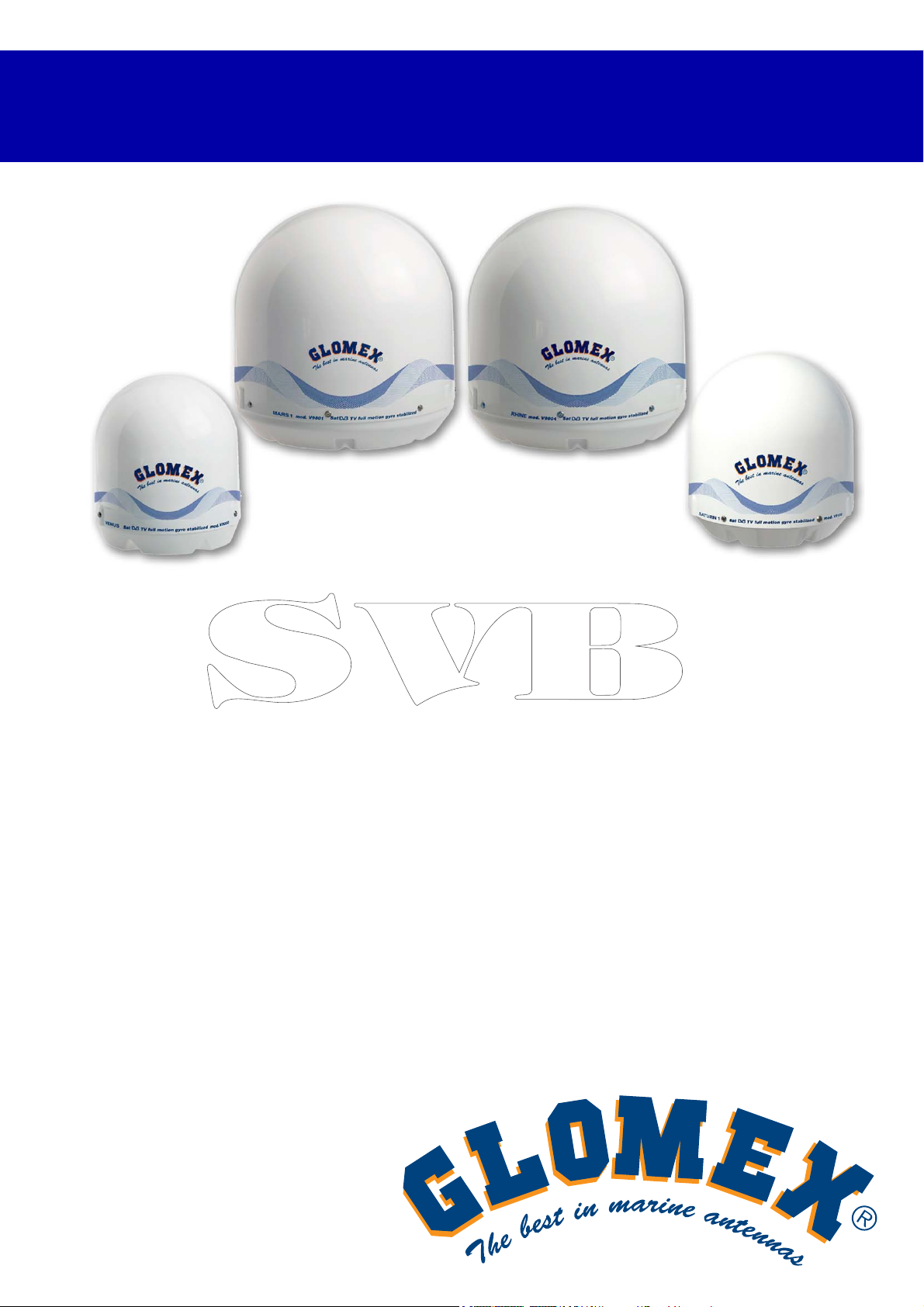
VENUS V9000
SATURN V9100 V9104 V9104SKEW
MARS V9801 V9804 V9804SKEW
RHINE R9804
ANTENNES TV SATELLITAIRES
POUR BATEAUX MARITIMES ET
FLUVIAUX
SÉRIE MK2+
MANUEL D’INSTALLATION ET UTILISATION
Page 88
VENUS SATURN MARS RHINE
FRANÇAIS
86
www.glomex.it
Page 89
VENUS SATURN MARS
INDEX
1. AVANT-PROPOS . . . . . . . . . . . . . . . . . . . . . . . . . . . . . . . . . . . . . . . . . . . . . . . . . . . . . . . 89
1.1 LETTRE DE LIVRAISON . . . . . . . . . . . . . . . . . . . . . . . . . . . . . . . . . . . . . . . . . . . . . . . . 89
1.2 IDENTIFICATION DE L’ANTENNE . . . . . . . . . . . . . . . . . . . . . . . . . . . . . . . . . . . . . . . . 89
1.3 GARANTIE . . . . . . . . . . . . . . . . . . . . . . . . . . . . . . . . . . . . . . . . . . . . . . . . . . . . . . . . . . . 89
1.4 RÈGLES DE SÉCURITÉ GÉNÉRALES. . . . . . . . . . . . . . . . . . . . . . . . . . . . . . . . . . . . . 90
1.5 ENVIRONNEMENT . . . . . . . . . . . . . . . . . . . . . . . . . . . . . . . . . . . . . . . . . . . . . . . . . . . . 90
2. DESCRIPTION DU PRODUIT. . . . . . . . . . . . . . . . . . . . . . . . . . . . . . . . . . . . . . . . . . . . . . 91
2.1 VENUS V9000 - SATURN V9100 - MARS V9801 . . . . . . . . . . . . . . . . . . . . . . . . . . . . . 91
2.2 SATURN V9104 - V9104SKEW - MARS V9804 - V9804SKEW . . . . . . . . . . . . . . . . . . 91
2.3 RHINE R9804. . . . . . . . . . . . . . . . . . . . . . . . . . . . . . . . . . . . . . . . . . . . . . . . . . . . . . . . . 91
3. CONTENU . . . . . . . . . . . . . . . . . . . . . . . . . . . . . . . . . . . . . . . . . . . . . . . . . . . . . . . . . . . . . 92
3.1 ACCESSOIRES OPTIONNELS (NON INCLUS) POUR L’UTILISATION
DES ANTENNES GLOMEX . . . . . . . . . . . . . . . . . . . . . . . . . . . . . . . . . . . . . . . . . . . . . . 96
4. OUTILS NÉCESSAIRES POUR LE MONTAGE (NON FOURNIS). . . . . . . . . . . . . . . . . . 96
5. INSTALLATION . . . . . . . . . . . . . . . . . . . . . . . . . . . . . . . . . . . . . . . . . . . . . . . . . . . . . . . . . 98
6. MONTAGE. . . . . . . . . . . . . . . . . . . . . . . . . . . . . . . . . . . . . . . . . . . . . . . . . . . . . . . . . . . . 100
6.1 GABARIT DE COUPE POUR RADÔME INFÉRIEUR . . . . . . . . . . . . . . . . . . . . . . . . . 108
6.2 GABARIT DE COUPE DE L’UNITÉ DE CONTRÔLE POUR L’INSTALLATION
SUR UNE PAROI VERTICALE . . . . . . . . . . . . . . . . . . . . . . . . . . . . . . . . . . . . . . . . . . 109
6.3 CALIBRAGE SKEW (MANUEL). . . . . . . . . . . . . . . . . . . . . . . . . . . . . . . . . . . . . . . . . . 110
6.4 GRILLE DE RÉGLAGE SKEW POUR L’EUROPE . . . . . . . . . . . . . . . . . . . . . . . . . . . 111
7. UTILISATION. . . . . . . . . . . . . . . . . . . . . . . . . . . . . . . . . . . . . . . . . . . . . . . . . . . . . . . . . . 113
8. CONSEILS POUR UNE UTILISATION CORRECTE . . . . . . . . . . . . . . . . . . . . . . . . . . . 116
8.1 FOOTPRINTS : ZONES DE TRANSMISSION SATELLITAIRES . . . . . . . . . . . . . . . . 117
9. ENTRETIEN. . . . . . . . . . . . . . . . . . . . . . . . . . . . . . . . . . . . . . . . . . . . . . . . . . . . . . . . . . . 119
9.1 ENTRETIEN PRÉVENTIF . . . . . . . . . . . . . . . . . . . . . . . . . . . . . . . . . . . . . . . . . . . . . . 119
9.2 PIÈCES DE RECHANGE . . . . . . . . . . . . . . . . . . . . . . . . . . . . . . . . . . . . . . . . . . . . . . .
119
FRANÇAIS
10. DÉPANNAGE . . . . . . . . . . . . . . . . . . . . . . . . . . . . . . . . . . . . . . . . . . . . . . . . . . . . . . . . . 120
11. RETOUR . . . . . . . . . . . . . . . . . . . . . . . . . . . . . . . . . . . . . . . . . . . . . . . . . . . . . . . . . . . . . 122
12. SPÉCIFICATIONS TECHNIQUES . . . . . . . . . . . . . . . . . . . . . . . . . . . . . . . . . . . . . . . . . 123
13. SUPPORT TECHNIQUE . . . . . . . . . . . . . . . . . . . . . . . . . . . . . . . . . . . . . . . . . . . . . . . . . 126
87
www.glomex.it
Page 90
VENUS SATURN MARS
FRANÇAIS
88
www.glomex.it
Page 91
1. AVANT-PROPOS
VENUS SATURN MARS
1.1 LETTRE DE LIVRAISON
Bienvenues : avec l’installation de cette antenne, le
monde de la télévision satellitaire monte à bord de
votre bateau.
Ce manuel a été rédigé afin de vous aider à une
correcte installation et un bon usage de l’antenne.
1.2 IDENTIFICATION DE L’ANTENNE
Pour toute communication avec GLOMEX ou un de
ses Centres d’Assistance, préciser toujours le
numéro de série et le modèle de l’antenne,
figurant à la deuxième page du manuel, sur la boîte
d’emballage, sur le côté arrière du disque
parabolique, au-dessous de l’unité de contrôle et
au-dessous de l’alimentateur.
1.3 GARANTIE
GLOMEX garantit les défauts de conformité des
antennes satellitaires série VENUS V9000,
SATURN V9100, V9104 et V9104SKEW, MARS
V9801, V9804 et V9804SKEW et RHINE R9804
pendant une période de 24 (vingt-quatre) mois à
compter de la date d’expédition.
Par garantie on entend la réparation ou le
remplacement de l’appareil qui présenterait des
défauts de conformité au contrat de vente, sans
aucun frais pour les matériaux.
Dans le cas d’un défaut de conformité, le
remplacement sera effectué sans aucun frais pour
le client.
La garantie sera valide seulement si le produit est
accompagné de la preuve d’achat (ticket de
caisse et/ou facture).
Le produit non conforme devra être rendu au
Centre d’Assistance ou au distributeur autorisé, qui
l’enverra à :
GLOMEX S.r.l.
Via Faentina 165/G
48124, Ravenne (Italie)
avec tous les accessoires fournis à l’achat.
La garantie est fournie par :
GLOMEX S.r.l.
Via Faentina 165/G
48124 Ravenne (Italie)
Le numéro de série ne devra être effacé ni rendu
illisible ; dans le cas contraire, la garantie pourra
être refusée.
S
Garder le manuel d’installation et utilisation avec
soin ! La perte du numéro de série annule le droit
de garantie !
La garantie ne s’applique pas en cas de
dommages causés par négligence, utilisation ou
installation non conforme aux instructions fournies,
modifications non autorisées, modifications du
produit ou du numéro de série, dommages causés
accidentellement ou par négligence de l’acheteur.
En outre, la garantie ne s’applique pas en cas de
dommages résultants du branchement de l’appareil
à une tension différente de celle indiquée, de
brusques changements de tension du réseau
auquel l’appareil est branché, ainsi qu’en cas de
dégâts causés par des infiltrations de liquide, par le
feu, par les décharges inductives/électrostatiques
ou des décharges provoquées par des éclairs,
surtensions ou autres phénomènes ne dépendant
pas de l’appareil.
Les parties sujettes à l’usure résultant de
l’utilisation comme, par exemple, câbles de
connexion, ceintures de transmission,
connecteurs, parties externes et supports en
plastique sont couverts par une garantie d’un an.
La garantie ne couvre pas : contrôles périodiques,
mise à jour du logiciel, réglages du produit,
entretien.
La période de garantie terminée, les interventions
de support technique seront effectuées en
facturant au client les frais des pièces remplacées,
la main d’œuvre, ainsi que les frais de transport,
selon le tarif en vigueur.
L’appareil sera remplacé ou réparé sous
garantie exclusivement après l’autorisation du
Département de Qualité de Glomex.
En cas de litige, le seul tribunal compétent est celui
de Ravenne (Italie).
ATTENTION
FRANÇAIS
www.glomex.it
89
Page 92
VENUS SATURN MARS
1.4 RÈGLES DE SÉCURITÉ GÉNÉRALES
Lire attentivement les règles de sécurité fournies et
observer les précautions indiquées afin de prévenir
tout risque potentiel et pour sauvegarder votre
intégrité et sécurité, avant d’effectuer toute
opération d’installation ou d’entretien.
Ce manuel contient les indications suivantes :
S
Ce symbole met en garde contre des dommages
potentiels à l’appareil qui pourraient impliquer la
sécurité de l’opérateur.
FRANÇAIS
Avec des avertissements spécifiques contre les
dangers potentiels pour la sécurité de l’opérateur
ou d’autres personnes directement impliquées.
Le manque de conformité à l’avertissement
précédé par les mots-clés mentionnés ci-dessus
(ATTENTION et DANGER) peut causer des
accidents graves ou même la mort des personnes
impliquées.
En outre, dans ce Manuel on a donné des
instructions avec des textes en italique, précédées
par le mot NOTE.
Les informations et spécifications données dans ce
manuel sont basées sur les informations
disponibles lorsque le manuel est écrit.
En cas de doute, n’hésitez pas à vous adresser à
GLOMEX S.r.l.
ATTENTION
S
DANGER
1.5 ENVIRONNEMENT
Ne pas jeter l’appareil en fin de vie avec les
ordures ménagères, mais le déposer à un endroit
prévu à cet effet par les pouvoirs publics pour son
recyclage. Vous aiderez, ainsi, à protéger
l’environnement.
Fig. 1
90
www.glomex.it
Page 93
2. DESCRIPTION DU PRODUIT
VENUS SATURN MARS
2.1 VENUS V9000 - SATURN V9100 MARS V9801
Elles sont des antennes TV satellitaires qui
garantissent une performance renouvelée dans la
réception et la poursuite du signal satellitaire
pendant la navigation, à l’ancre et pendant le
mouillage.
Elles sont équipées du nouveau disque
parabolique HPD (High-Performance Dish) à haute
prestation, combiné avec le système innovant STO
(Silent Tracking Operation) de réduction du bruit.
Elles sont équipées d’un système de compensation
performant du roulis et du tangage du bateau, qui
se compose de stabilisateurs gyroscopiques (EGS)
et d’une articulation tournante coaxiale simple
(CRJ), permettant à l’antenne de stabiliser la
réception du signal en tournant infiniment sur son
axe azimut, puisque l’enroulement du câble coaxial
n’est pas nécessaire. Elles permettent la
connexion d’un seul récepteur à la fois.
Elles sont également équipées d’une unité de
contrôle qui peut être intégrée dans le tableau de
bord électrique.
8 satellites sont déjà disponibles dans l’unité de
contrôle et sont reconnus par le système de
reconnaissance NIT (Network Identification Table).
Elles sont préréglées pour une mise à jour future.
2.2 SATURN V9104 - V9104SKEW - MARS
V9804 - V9804SKEW
Elles sont antennes TV satellitaires qui non
seulement garantissent des standards de
performance élevés dans la réception et la
poursuite du signal pendant la navigation, à l’ancre
et pendant le mouillage, mais permettent aussi le
branchement de jusqu’à 16 décodeurs
indépendants sur le même bateau.
Elles sont équipées du nouveau disque
parabolique HPD (High-Performance Dish) à haute
prestation, combiné avec le système innovant STO
(Silent Tracking Operation) de réduction du bruit.
Elles sont équipées d’un système de compensation
performant du roulis et du tangage du bateau, qui
se compose de stabilisateurs gyroscopiques
(EGS), d’une articulation tournante coaxiale
multiple (MCRJ) et d’une boîte de commutation
multiple pour la connexion de plusieurs décodeurs
indépendants (4 sorties pour le commutateur
multiple, jusqu’à maximum 16 pour chaque
antenne).
L’antenne peut tourner infiniment sur son axe
puisqu’il n’est pas nécessaire d’enrouler le câble
coaxial ou d’interrompre la vision de la télé. Elles
sont équipées d’une unité de contrôle qui peut être
intégrée dans le tableau de bord électrique.
Dans la version SKEW, elles sont équipées d’un
système de compensation innovant qui, selon la
position géographique, agit directement sur le LNB,
changeant automatiquement son inclinaison et
optimisant la polarisation pour obtenir la meilleure
qualité de signal possible.
8 satellites sont déjà disponibles dans l’unité de
contrôle et sont reconnus par le système de
reconnaissance NIT (Network Identification Table).
Elles sont préréglées pour une mise à jour future.
2.3 RHINE R9804
Rhine R9804 est la meilleure antenne TV
satellitaire pour bateaux fluviaux conçue par
Glomex. Identique pour dimensions à Mars V9804
(diamètre du disque 600 mm), permet de brancher
jusqu’à 16 décodeurs indépendants sur le même
bateau. Cette antenne est équipée avec une
articulation tournante multi-coaxiale (MCRJ) et
avec une boîte de commutation multiple pour le
raccordement des plusieurs décodeurs
indépendants (4 sorties pour la commutation
multiple, jusqu’à une quantité maximale de 16 par
antenne). Rhine R9804 a été conçue pour obtenir
une performance excellente pendant la navigation
fluviale grâce au nouveau hardware et logiciel
d’inspiration mobile, qui empêchent la perte du
signal TV satellitaire, même en présence de ponts
et d’obstacles le long des rives. Ces
caractéristiques font de Rhine le choix idéal pour
regarder la télévision dans des bateaux fluviaux et
en cas de mauvaises conditions météorologiques.
Elle est conçue pour une mise à jour future.
FRANÇAIS
www.glomex.it
91
Page 94
VENUS SATURN MARS
3. CONTENU
L’antenne satellitaire est envoyée emballée dans
une boîte en carton et scellée avec le feuillard
GLOMEX “SCEAU DE SÉCURITÉ”, qui a la
fonction de sceau de GARANTIE DU CONTENU.
A la réception, contrôler que :
- l’emballage soit entier et que le feuillard de
sécurité soit présent ;
- la fourniture corresponde aux détails de la com-
mande ;
- l’antenne ou ses accessoires ne soient pas
endommagés.
En cas de dommages ou pièces manquantes,
informer immédiatement le distributeur, si possible
FRANÇAIS
avec des photos correspondantes.
Les tableaux ci-dessous listent les composants
contenus dans l’emballage, indiquant les quantités
et le code GLOMEX (si fourni).
92
www.glomex.it
Page 95
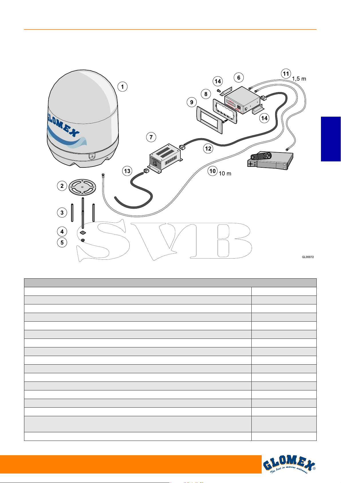
VENUS V9000 - SATURN V9100 - MARS V9801
VENUS SATURN MARS
FRANÇAIS
Récepteur satellitaire
(non fourni)
Fig. 1B
VENUS V9000/SATURN V9100/MARS V9801 Fig. 1B
Composant Code GLOMEX
Unité antenne V9000 (1) 3.010.0015
Unité antenne V9100 (1) 3.010.0016
Unité antenne V9801 (1) 3.010.0017
Garniture base (2) 4.010.0415
Barres filetées M8 x 100 (4 pcs) (3) 4.100.0118
Renforts de fixage (4 pcs) (4) 4.020.0247
Écrous autobloquants M8 (4 pcs) (5) 4.100.0019
Unité de contrôle (6) 4.120.0042
Alimentateur pour unité de contrôle (7) 4.120.0043
Soutien Vimar pour l’installation de l’unité de contrôle (8) 4.010.0153
Cadre pour installation en encastrement (9) 4.010.0154
Câble de 10 m pour connexion antenne - unité de contrôle (10) V9139/10
Câble de 1,5 m pour connexion amplificateur de ligne - décodeur (11) V9143
Câble d’alimentation pour unité de contrôle - alimentateur (12) 4.070.0100
Câble de connexion pour alimentateur - interrupteur magnétothermique sur le
tableau de bord (13)
Brides pour le montage de l’unité de contrôle sur une surface horizontale (14) 4.020.0611
4.070.0101
www.glomex.it
93
Page 96
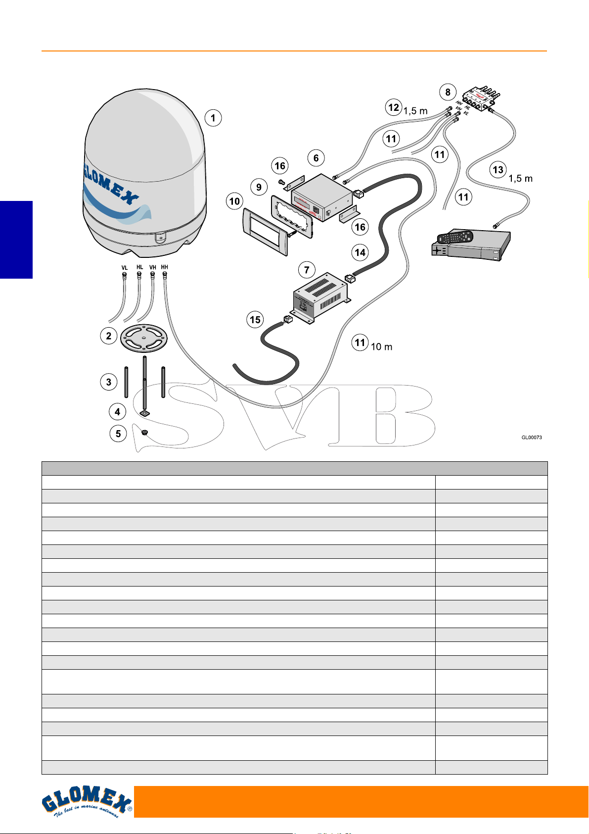
VENUS SATURN MARS
SATURN V9104 - MARS V9804 - SATURN V9104SKEW - MARS V9804SKEW
FRANÇAIS
Récepteur satellitaire
(non fourni)
Fig. 1C
SATURN V9104 - V9104 SKEW/MARS V9804 - V9804 SKEW Fig. 1C
Composant Code GLOMEX
Unité antenne V9104 (1) 3.010.0018
Unité antenne V9104 SKEW (1) 3.010.0019
Unité antenne V9804 (1) 3.010.0020
Unité antenne V9804 SKEW (1) 3.010.0021
Garniture base (2) 4.010.0415
Barres filetées M8 x 100 (4 pcs) (3) 4.100.0118
Renforts de fixage (4 pcs) (4) 4.020.0247
Écrous autobloquants M8 (4 pcs) (5) 4.100.0019
Unité de contrôle (6) 4.120.0042
Alimentateur pour unité de contrôle (7) 4.120.0043
Commutateur multiple (8) V9191
Soutien Vimar pour l’installation de l’unité de contrôle (9) 4.010.0153
Cadre pour installation en encastrement (10) 4.010.0154
Câbles de 10 m pour la connexion antenne - unité de contrôle et antenne -
commutateur multiple (11) (4 pièces)
Câble de 1,5 m pour connexion unité de contrôle - commutateur multiple (12) V9143
Câble de 1,5 m pour connexion commutateur multiple - décodeur (13) V9143
Câble d’alimentation pour unité de contrôle - alimentateur (14) 4.070.0100
Câble de connexion pour alimentateur - interrupteur magnétothermique sur le
tableau de bord (15)
Brides pour le montage de l’unité de contrôle sur une surface horizontale (16) 4.020.0611
V9139/10
4.070.0101
94
www.glomex.it
Page 97
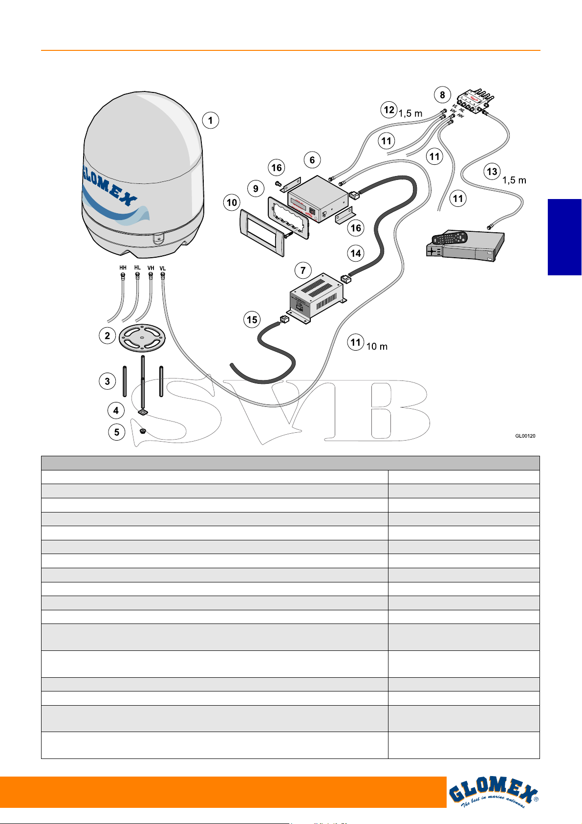
RHINE R9804
VENUS SATURN MARS
Récepteur satellitaire
(non fourni)
Fig. 1D
RHINE R9804 Fig. 1D
Composant Code GLOMEX
Unité antenne R9804 (1) 3.010.0023
Garniture base (2) 4.010.0415
Barres filetées M8 x 100 (4 pcs) (3) 4.100.0118
Renforts de fixage (4 pcs) (4) 4.020.0247
Écrous autobloquants M8 (4 pcs) (5) 4.100.0019
Unité de contrôle (6) 4.120.0042
Alimentateur pour unité de contrôle (7) 4.120.0043
Commutateur multiple (8) V9191
Soutien Vimar pour l’installation de l’unité de contrôle (9) 4.010.0153
Cadre pour installation en encastrement (10) 4.010.0154
Câbles de 10 m pour la connexion antenne - unité de contrôle et
antenne - commutateur multiple (11) (4 pièces)
Câble de 1,5 m pour connexion unité de contrôle - commutateur multiple
(12)
Câble de 1,5 m pour connexion commutateur multiple - décodeur (13) V9143
Câble d’alimentation pour unité de contrôle - alimentateur (14) 4.070.0100
Câble de connexion pour alimentateur - interrupteur magnétothermique
sur le tableau de bord (15)
Brides pour le montage de l’unité de contrôle sur une surface
horizontale (16)
V9139/10
V9143
4.070.0101
4.020.0611
FRANÇAIS
www.glomex.it
95
Page 98
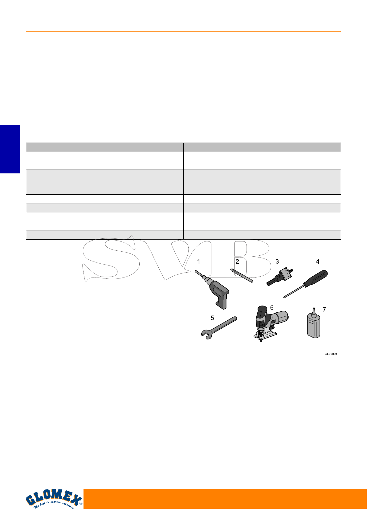
VENUS SATURN MARS
3.1 ACCESSOIRES OPTIONNELS (NON
INCLUS) POUR L’UTILISATION DES
ANTENNES GLOMEX
Pour être capables d’utiliser votre nouvelle antenne
satellitaire GLOMEX pour bateaux, il faudra se
procurer ou acheter aussi :
- un téléviseur ;
- un récepteur satellitaire pour la sélection des
chaînes.
Le tableau ci-dessous liste tous les composants
optionnels GLOMEX, avec code correspondant.
Accessoire optionnel Code GLOMEX
Décodeur satellitaire i-CAN 1110SV TIVÙSAT
230 VAC - 12 VDC
FRANÇAIS
Décodeur XDome combiné numérique terrestre satellitaire HD (DVB-T + DVB-S + DVB-S2)
compatible avec SKY ITALIA - 230 VAC
Support en acier inoxydable 0°- 5° V9500
Radôme jumeau V9... TWIN - R9804 TWIN
Peinture du radôme - couleur RAL choisie par le
client
Amplificateur de ligne V9115
V9193
V9192
SATPAINT
4. OUTILS NÉCESSAIRES POUR LE
MONTAGE (NON FOURNIS)
Se procurer tous les outils et les matériaux dans la
liste suivante. Ils seront nécessaires pour
compléter l’installation.
- Perceuse électrique (1).
- Mèche de perceuse de 8,5 mm pour le montage
du radôme (2).
- Fraise trépan de 28 mm pour percer le trou de
passage pour le câble du connecteur (3) de
l’antenne.
- Tournevis étoile (avec des dimensions adéqua-
tes pour l’installation de l’unité de contrôle) (4).
- Clé de 11 mm (pour l’installation des connec-
teurs du câble coaxial) (5).
- Scie alternative (pour créer un logement en cas
d’installation en encastrement dans la paroi de
l’unité de contrôle ; utiliser le gabarit fourni à la
page 109) (6).
- LOCTITE ® 638 (7)
Fig. 2
96
www.glomex.it
Page 99
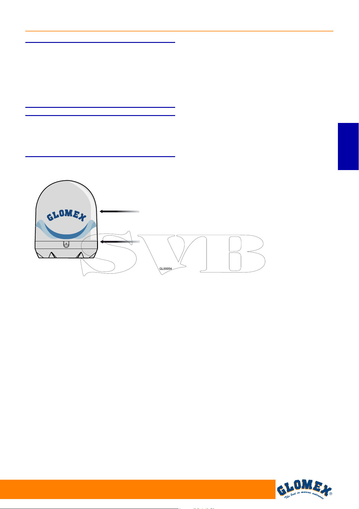
VENUS SATURN MARS
S
Programmer l’installation entière avant de commencer !
Veuillez tenir compte de la disposition des différents composants, de la distance entre eux, de la
longueur des câbles différents et de l’accessibilité
de l’appareil une fois installé.
S
Soulever toujours l’antenne du radôme inférieur.
Ne jamais soulever l’antenne du radôme supérieur
ou de ses composants internes.
ATTENTION
ATTENTION
Radôme supérieur
FRANÇAIS
Fig. 3
Radôme inférieur
www.glomex.it
97
Page 100
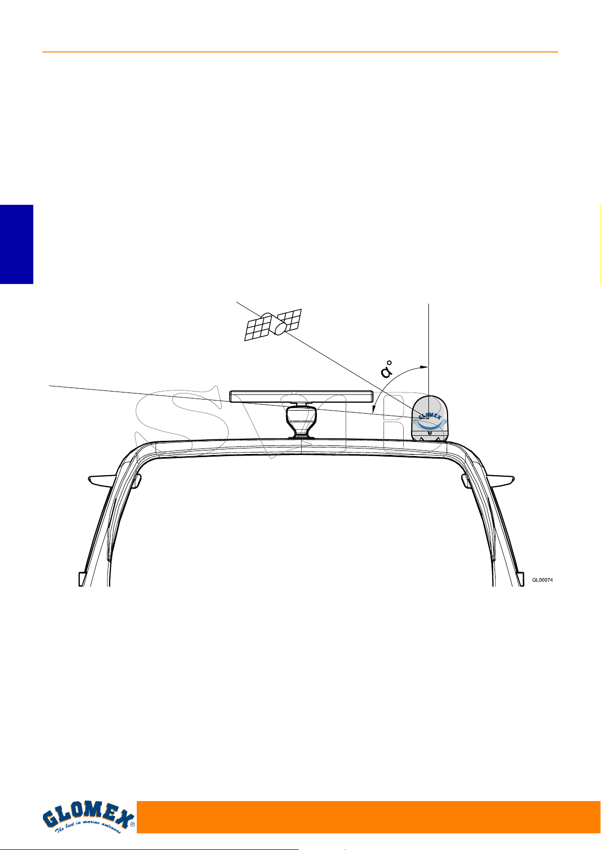
VENUS SATURN MARS
5. INSTALLATION
Avant de commencer l’installation, respecter les
directives suivantes :
- veuillez noter que la meilleure position pour pla-
cer l’antenne TV satellitaire c’est au milieu du
bateau, dans l’endroit le plus bas possible.
- réduire au minimum les obstructions. L’antenne
nécessite une vue claire du ciel pour recevoir les
signaux télé satellitaires. Un nombre réduit d’obstacles comporte un meilleur fonctionnement du
système.
Tout corps étranger (drapeaux, antennes, antennes radar, mâts de bateaux à voile, grues, ponts,
etc.) entre l’antenne et le satellite bloque le signal
et empêche une réception correcte.
FRANÇAIS
- s’assurer que la surface de montage soit assez
grande pour l’installation de la base de l’antenne.
Signal bloqué !
- s’assurer que la surface de montage soit assez
résistante et rigide pour soutenir le poids de
l’antenne et les vibrations qui peuvent se produire.
- ne pas installer l’antenne près des haut-parleurs
ou de sources magnétiques. Si ce n'est pas possible, il sera nécessaire de compenser la source
magnétique, en faisant attention à ne pas interférer avec le compas de bord.
- l’antenne nécessite d’un angle de levage
5° et 90° pour recevoir les signaux satellitaires
(Fig. 4).
α entre
Fig. 4
Antenne télé
Roll-bar
α = angle de levage
98
www.glomex.it
 Loading...