

Page 1
SATURN V9104S2U V9104SKEWS2U
MARS V9804S2U V9804SKEWS2U
RHINE R9804S2U R9804SERS2U
MARINE AND FLUVIAL SATELLITE TV
ANTENNAS WITH USB CONTROL UNIT
SERIES MK3
USER AND INSTALLATION MANUAL
Page 2
SATURN MARS RHINE
ENGLISH
42
www.glomex.it
Page 3

SATURN MARS RHINE
INDEX
1. FOREWORD . . . . . . . . . . . . . . . . . . . . . . . . . . . . . . . . . . . . . . . . . . . . . . . . . . . . . . . . . . . 44
1.1 DELIVERY LETTER. . . . . . . . . . . . . . . . . . . . . . . . . . . . . . . . . . . . . . . . . . . . . . . . . . . . 44
1.2 ANTENNA IDENTIFICATION. . . . . . . . . . . . . . . . . . . . . . . . . . . . . . . . . . . . . . . . . . . . . 44
1.3 WARRANTY. . . . . . . . . . . . . . . . . . . . . . . . . . . . . . . . . . . . . . . . . . . . . . . . . . . . . . . . . . 44
1.4 GENERAL SAFETY RULES . . . . . . . . . . . . . . . . . . . . . . . . . . . . . . . . . . . . . . . . . . . . . 45
1.5 ENVIRONMENT. . . . . . . . . . . . . . . . . . . . . . . . . . . . . . . . . . . . . . . . . . . . . . . . . . . . . . . 45
2. PRODUCT DESCRIPTION . . . . . . . . . . . . . . . . . . . . . . . . . . . . . . . . . . . . . . . . . . . . . . . . 46
2.1 SATURN V9104S2U - V9104SKEWS2U - MARS V9804S2U - V9804SKEWS2U . . . . 46
2.2 RHINE R9804S2U - R9804SERS2U . . . . . . . . . . . . . . . . . . . . . . . . . . . . . . . . . . . . . . . 46
3. CONTENTS . . . . . . . . . . . . . . . . . . . . . . . . . . . . . . . . . . . . . . . . . . . . . . . . . . . . . . . . . . . . 47
3.1 OPTIONAL ACCESSORIES (NOT INCLUDED) TO USE GLOMEX ANTENNAS. . . . . 50
4. NECESSARY TOOLS FOR ASSEMBLY (NOT PROVIDED) . . . . . . . . . . . . . . . . . . . . . . 50
5. INSTALLATION . . . . . . . . . . . . . . . . . . . . . . . . . . . . . . . . . . . . . . . . . . . . . . . . . . . . . . . . . 51
6. ASSEMBLY . . . . . . . . . . . . . . . . . . . . . . . . . . . . . . . . . . . . . . . . . . . . . . . . . . . . . . . . . . . . 53
6.1 LOWER RADOME CUTTING TEMPLATE. . . . . . . . . . . . . . . . . . . . . . . . . . . . . . . . . . . 61
6.2 CONTROL UNIT CUTTING TEMPLATE FOR INSTALLATION
ON A VERTICAL WALL . . . . . . . . . . . . . . . . . . . . . . . . . . . . . . . . . . . . . . . . . . . . . . . . . 62
6.3 SKEW CALIBRATION (MANUAL) . . . . . . . . . . . . . . . . . . . . . . . . . . . . . . . . . . . . . . . . . 63
6.4 SKEW ADJUSTMENT GRID FOR EUROPE . . . . . . . . . . . . . . . . . . . . . . . . . . . . . . . . . 64
7. USE . . . . . . . . . . . . . . . . . . . . . . . . . . . . . . . . . . . . . . . . . . . . . . . . . . . . . . . . . . . . . . . . . . 66
8. TIPS FOR CORRECT USAGE . . . . . . . . . . . . . . . . . . . . . . . . . . . . . . . . . . . . . . . . . . . . . 69
8.1 FOOTPRINTS: SATELLITE TRANSMISSION AREAS . . . . . . . . . . . . . . . . . . . . . . . . . 70
ENGLISH
9. MAINTENANCE. . . . . . . . . . . . . . . . . . . . . . . . . . . . . . . . . . . . . . . . . . . . . . . . . . . . . . . . . 72
9.1 PREVENTIVE MAINTENANCE . . . . . . . . . . . . . . . . . . . . . . . . . . . . . . . . . . . . . . . . . . . 72
9.2 SPARE PARTS . . . . . . . . . . . . . . . . . . . . . . . . . . . . . . . . . . . . . . . . . . . . . . . . . . . . . . . 72
9.3 SOFTWARE UPDATE BY FLASH USB. . . . . . . . . . . . . . . . . . . . . . . . . . . . . . . . . . . . . 73
10. TROUBLESHOOTING. . . . . . . . . . . . . . . . . . . . . . . . . . . . . . . . . . . . . . . . . . . . . . . . . . . . 75
11. RESHIPPING. . . . . . . . . . . . . . . . . . . . . . . . . . . . . . . . . . . . . . . . . . . . . . . . . . . . . . . . . . . 77
12. TECHNICAL SPECIFICATIONS . . . . . . . . . . . . . . . . . . . . . . . . . . . . . . . . . . . . . . . . . . . . 78
13. TECHNICAL SUPPORT . . . . . . . . . . . . . . . . . . . . . . . . . . . . . . . . . . . . . . . . . . . . . . . . . . 80
www.glomex.it
43
Page 4
SATURN MARS RHINE
1. FOREWORD
1.1 DELIVERY LETTER
Welcome: with the installation of this antenna, the
world of satellite television comes on board your
boat.
This manual has been drafted in order to help you
with the correct installation and operation of the
antenna.
ENGLISH
1.2 ANTENNA IDENTIFICATION
When calling GLOMEX or an authorized Service
Centre, always provide the serial number and the
model of the antenna, shown on the second page
of the manual, on the packaging, on the backside
of the dish, under the control unit and under the
power supply.
1.3 WARRANTY
GLOMEX guarantees the satellite antennas series
SATURN4 V9104S2U and V9104SKEWS2U,
MARS4 V9804S2U, V9804SKEWS2U and
RHINE R9804S2U, R9804SERS2U against conformity defects for a period of 24 (twenty-four)
months from the date of sales.
Warranty is intended as the repair or replacement
of the equipment showing conformity defects when
entering the sales contract, with no charge for the
materials.
In case of conformity defects, the customer is entitled to the replacement of the goods with no
charge.
The warranty is only valid if the product comes with
a valid proof of purchase (receipt or invoice).
The non-conforming product must be sent back to
a Service Centre or authorized retailer, who will forward it to:
GLOMEX S.r.l.
Via Faentina 165/G
48124, Ravenna (Italy)
along with all the accessories supplied at purchase.
The serial number must neither be erased nor
made illegible, otherwise the warranty will be
voided.
S
Conserve the installation and user manual with
care! Losing the serial number makes the warranty
null and void!
The warranty does not apply in case of damage
due to carelessness, use or installation not compliant with the instructions given, tampering, product
or serial number modification, damage due to accidental causes or to the buyer’s negligence.
Moreover, warranty does not apply in case of damage consequent to connections of the equipment to
different voltages than those indicated or to sudden
voltage variations of the network the equipment is
connected to, as well as in case of damage caused
by leakage, fire, inductive/electrostatic discharges
or discharges due to lightning, use of cables different to those provided, overvoltages or other phenomena not related to the equipment.
The parts subject to wear consequent to use such
as connection cables, driving belts, connectors,
external parts and plastic supports are covered by
a one-year period warranty.
The following are not covered by warranty: periodic
monitoring, software updates, settings of the product, maintenance.
After the expiration of the warranty period, the technical support activities will be carried out charging
the customer for the replaced parts, the labour
costs and freight charges, according to current
rates.
The equipment will be replaced or repaired
under warranty only and exclusively on Glomex
quality department’s approval.
Should any dispute rise, the place of jurisdiction will
exclusively be Ravenna (Italy).
WARNING
The warranty is provided by:
GLOMEX S.r.l.
Via Faentina 165/G
48124 Ravenna (Italy)
44
www.glomex.it
Page 5
1.4 GENERAL SAFETY RULES
Fig. 1
Carefully read the instructions given and follow the
precautions indicated to prevent potential hazards
and to safeguard your health and safety, before
carrying out any installation and maintenance operation.
This manual contains the following indications:
SATURN MARS RHINE
S
This symbol warns against potential damage to the
equipment which could involve the operator’s
safety.
S
With specific warnings against potential dangers
for the safety of the operator or other directly
involved persons.
Failure to comply with the instructions preceded by
the above-mentioned keywords (WARNING and
DANGER) can cause serious accidents or even
the death of the persons involved.
Moreover, in this Manual, some instructions are
given with text in italics, preceded by the word
NOTE.
The information and specifications given in this
manual are based upon the information available at
the moment it is written.
In case of doubts, do not hesitate to contact
GLOMEX S.r.l.
WARNING
DANGER
ENGLISH
1.5 ENVIRONMENT
Do not throw the appliance away with the normal
household waste at the end of its life, but hand it in
at an official point for recycling. By doing this, you
will help preserve the environment.
www.glomex.it
45
Page 6

SATURN MARS RHINE
2. PRODUCT DESCRIPTION
2.1 SATURN V9104S2U - V9104SKEWS2U
- MARS V9804S2U - V9804SKEWS2U
They are satellite antennas equipped with the
DVB-S2 technology in order to be able to receive
channels in FULL HD and 4K andensure high
standards in the acquisition and maintenance of
the satellite signal both when cruising and when
ENGLISH
riding the anchor or at the dock. They enable connection of up to 16 independent decoders on the
same boat. These satellite TV antenna models are
equipped with the new control unit with USB input
for faster and easier software update. The new
control unit also has a built-in power supply to
simplify installation and reduce wiring.
They are provided with the HPD (High-Performance Dish) parabolic dish, combined with the
innovative STO (Silent Tracking Operation) noise
reduction system. They are equipped with an efficient compensation system of the boat’s rolling and
pitching movements consisting of electronic gyrostabilizers (EGS), a multiple coaxial rotating joint
(MCRJ) and a multiswitch box for the connection of
more independent decoders (4 outputs for multiswitch, up to a maximum quantity of 16 per
antenna).
The antenna can turn infinitely around its axis,
since no coaxial cable winding and no interruption
of TV reception are needed. They are equipped
with a control unit which can be embedded into the
on-board electric panel.
In the SKEW version, they are provided with the
innovative compensation system which, according
to the geographic position, directly operates on the
LNB, automatically changing its inclination and
optimizing polarization to obtain the best possible
signal quality.
8 satellites are already available on the control unit
and are recognized through the NIT (Network Identification Table) system. They are prearranged for
future updating.
2.2 RHINE R9804S2U - R9804SERS2U
Rhine R9804S2U/R9804SERS2U is the best satellite TV antenna for river boats designed by Glomex
and is equipped with the DVB-S2 technology in
order to be able to receive channels in FULL HD
and 4K and ensure high standards in the acquisition and maintenance of the satellite signal. Identical in dimensions to Mars V9804S2U (dish
diameter 600 mm), it allows the connection of up to
16 independent decoders on the same boat. This
antenna is equipped with a multiple coaxial rotating
joint (MCRJ) and with a multiswitch box for the connection of more independent decoders (4 outputs
for multiswitch, up to a maximum quantity of 16 per
antenna).
Rhine R9804S2U is equipped with the new control
unit with USB input for faster and easier software
update. The new control unit also has a built-in
power supply to simplify installation and reduce
wiring. Rhine has been designed to obtain an outstanding performance in fluvial navigation thanks to
the new hardware and software of mobile inspiration, which prevent losing the satellite TV signal
even in the presence of bridges and obstacles
along the banks. These characteristics make Rhine
the ideal choice to watch TV in river boats and in
case of bad weather conditions.
It is prearranged for future updating.
46
www.glomex.it
Page 7

3. CONTENTS
The satellite antenna is sent packed in a cardboard
box and sealed with the GLOMEX “SAFETY SEAL”
hoop, which has the function of CONTENT WARRANTY seal.
Upon receipt, check that:
- the packaging is whole and the warranty hoop is
present;
- the supply matches the order specifications;
- the antenna and its accessories are not damaged.
In case of damage or missing parts, immediately
inform the Retailer, if possible with appropriate
photos.
The following tables list the components contained
in the package, indicating the quantities and the
GLOMEX code (if provided).
SATURN MARS RHINE
ENGLISH
www.glomex.it
47
Page 8
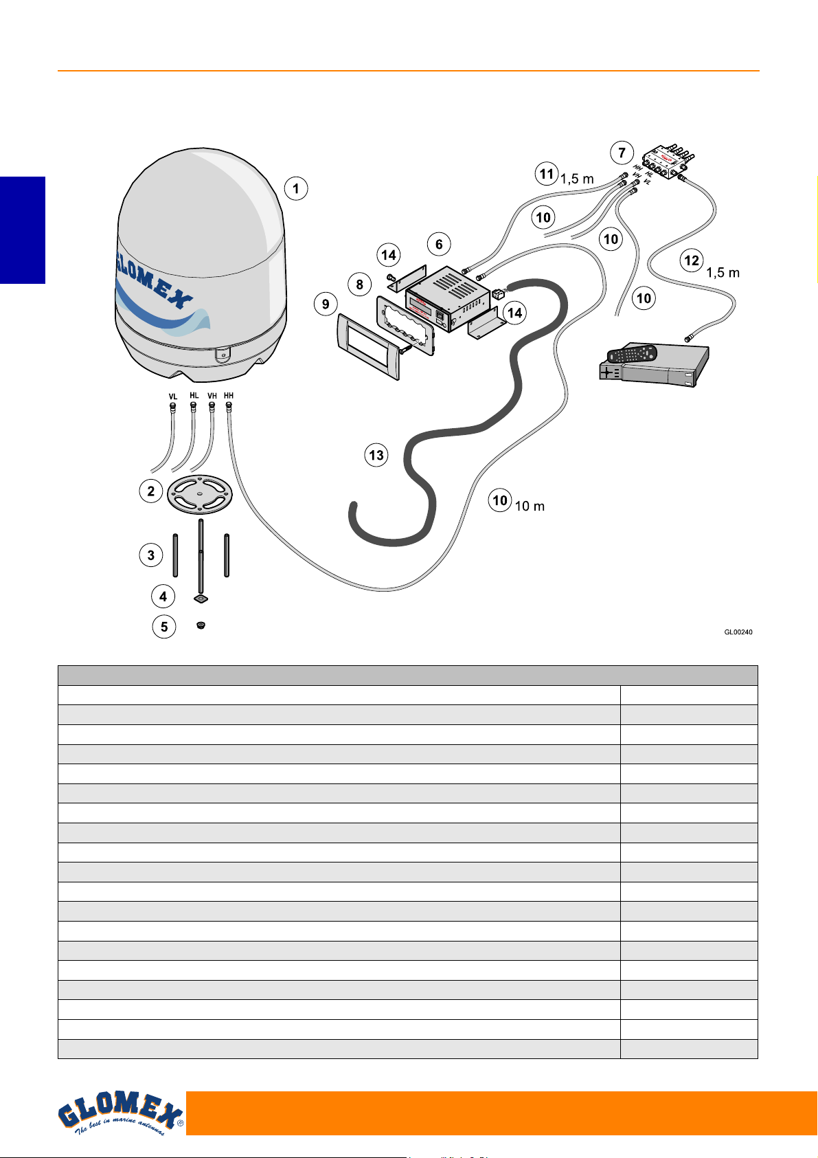
SATURN MARS RHINE
Fig. 1C
Satellite receiver (not
provided)
SATURN V9104S2U - MARS V9804S2U - SATURN V9104SKEWS2U - MARS V9804SKEWS2U RHINE R9804S2U
ENGLISH
SATURN V9104S2U and V9104SKEWS2U - MARS V9804S2U and V9804SKEWS2U - RHINE R9804S2U Fig. 1C
Component GLOMEX code
V9104S2U antenna unit (1) 3.010.0018
V9104SKEWS2U antenna unit (1) 3.010.0019
V9804S2U antenna unit (1) 3.010.0020
V9804SKEWS2U antenna unit (1) 3.010.0021
R9804S2U antenna unit (1) 3.010.0020
Base seal (2) 4.010.0415A
M8 x 100 threaded bars (4 pcs) (3) 4.100.0118
Fastening reinforcements (4 pcs) (4) 4.020.0247
M8 self-locking nuts (4 pcs) (5) 4.100.0019
USB DVB-S2 control unit (6) 4.120.0268
Multiswitch (7) V9191
Vimar support for control unit fastening (8) 4.010.0153
Frame for built-in installation (9) 4.010.0154
10 m cables for antenna - control unit and antenna - multiswitch connection (10) (4 pcs) V9139/10
1.5 m cable for control unit - multiswitch connection (11) V9143
1.5 m cable for multiswitch - decoder connection (12) V9143
Connection cable for control unit - magneto-thermal switch on the on-board panel (13) 4.070.0101
Brackets for fastening the control unit on a horizontal surface (14) 4.020.0611
48
www.glomex.it
Page 9
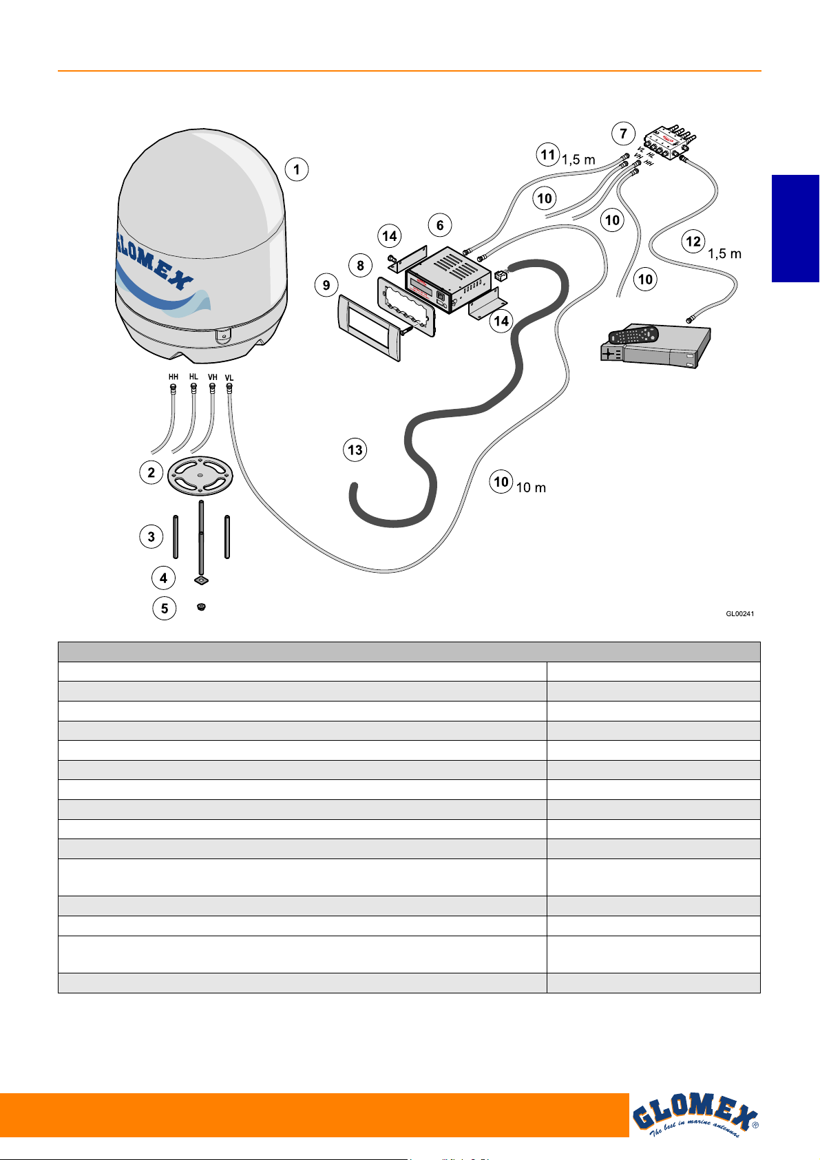
RHINE R9804SERS2U
Fig. 1D
Satellite receiver (not
provided)
SATURN MARS RHINE
ENGLISH
RHINE R9804SERS2U Fig. 1D
Component GLOMEX code
R9804SERS2U antenna unit (1) 3.010.0023
Base seal (2) 4.010.0415A
M8 x 100 threaded bars (4 pcs) (3) 4.100.0118
Fastening reinforcements (4 pcs) (4) 4.020.0247
M8 self-locking nuts (4 pcs) (5) 4.100.0019
USB DVB-S2 control unit (6) 4.120.0268
Multiswitch (7) V9191
Vimar support for control unit fastening (8) 4.010.0153
Frame for built-in installation (9) 4.010.0154
10 m cables for antenna - control unit and antenna - multiswitch
connection (10) (4 pcs)
1.5 m cable for control unit - multiswitch connection (11) V9143
1.5 m cable for multiswitch - decoder connection (12) V9143
Connection cable for control unit - magneto-thermal switch on the on-
board panel (13)
Brackets for fastening the control unit on a horizontal surface (14) 4.020.0611
V9139/10
4.070.0101
www.glomex.it
49
Page 10
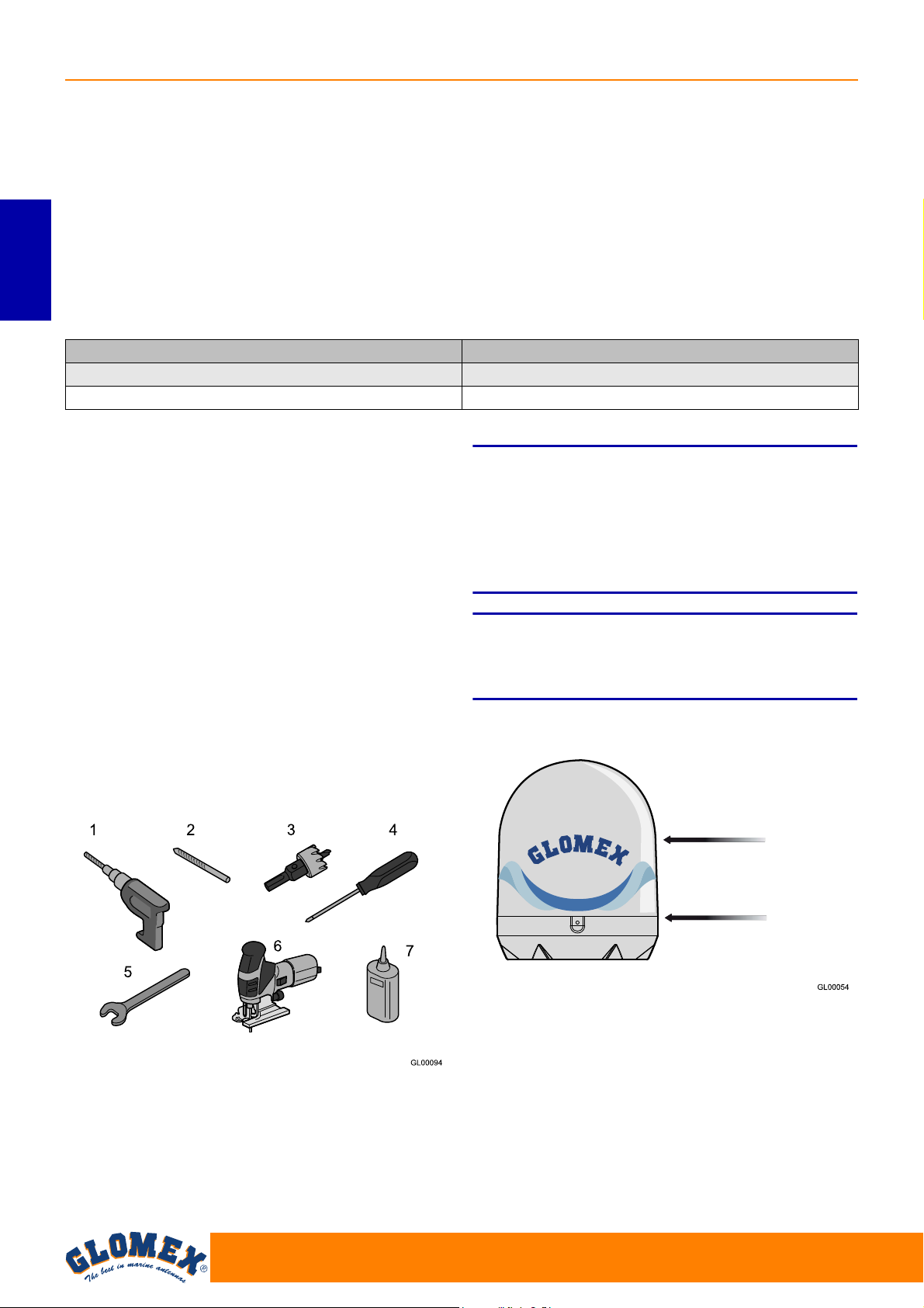
SATURN MARS RHINE
Fig. 2
Fig. 3
Upper radome
Lower radome
3.1 OPTIONAL ACCESSORIES (NOT
INCLUDED) TO USE GLOMEX
ANTENNAS
To be able to use your new GLOMEX satellite
antenna for boats, you will have to procure or buy
also:
- a TV set;
- a satellite receiver for channel selection.
ENGLISH
The table below lists all the GLOMEX optional
components, with relevant code.
Optional accessory GLOMEX code
Stainless steel support 0°- 5° V9500
Twin radome V9... TWIN - R9804 TWIN
4. NECESSARY TOOLS FOR
ASSEMBLY (NOT PROVIDED)
Procure all tools and materials listed below. They
will be necessary to complete installation.
- Electric drill (1).
- 8.5 mm drill tip for radome assembly (2).
- 28 mm hollow mill for drilling the passage hole
for the antenna connector cable (3).
- Phillips screwdriver (with adequate dimensions
for control unit installation) (4).
- 11 mm wrench (for the installation of the coaxial
cable connectors) (5).
- Reciprocating saw (to create the compartment
in case of wall built-in installation of the control
unit; use the template provided on page 62) (6).
- LOCTITE ® 638 (7)
S
Plan the whole installation before proceeding!
Please consider the lay-out of the various components, the distance between them, the length of the
various cables and the accessibility to the equipment once it is installed.
S
Always lift the antenna from the lower radome and
never from the upper radome or any part inside it.
WARNING
WARNING
50
www.glomex.it
Page 11
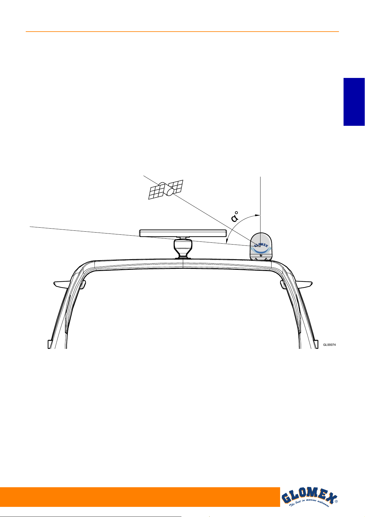
5. INSTALLATION
Roll-bar
Fig. 4
TV antenna
Obstructed signal!
= lifting angle
SATURN MARS RHINE
Before proceeding with the installation, please
respect the following guidelines:
- please remember that the best position for the
satellite TV antenna is in the middle of the boat,
in the lowest possible position.
- minimize obstruction. The antenna requires a
clear view of the sky in order to receive satellite
TV signals. The fewer the obstacles, the better
the system operation.
Any foreign body (flags, antennas, radar antennas, sailboat masts, cranes, bridges, etc.)
between the antenna and the satellite obstructs
the signal and prevents correct receipt.
- make sure that the mounting surface is wide
enough for the antenna base to be installed.
- make sure that the mounting surface is resistant
and rigid enough to support the weight of the
antenna and the vibrations which could occur.
- do not install the antenna near speakers or magnetic sources. In case it is not possible, it is necessary to compensate the magnetic source,
paying attention not to interfere with the on-board
compass.
- the antenna requires a lifting angle
and 90° to receive satellite signals (Fig. 4).
between 5°
ENGLISH
www.glomex.it
51
Page 12
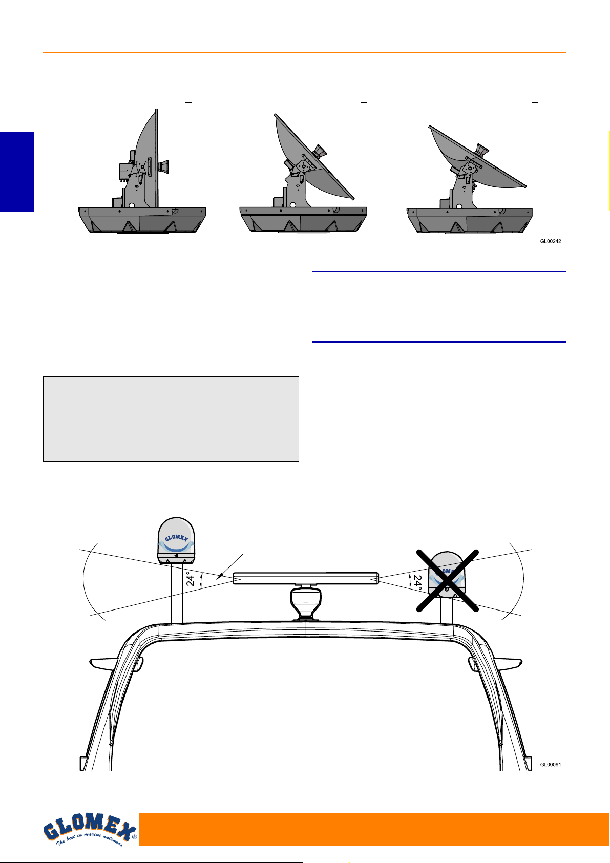
SATURN MARS RHINE
Fig. 5
NORTHERN EUROPE (~ 15°) CENTRAL EUROPE (~ 35°) SOUTHERN EUROPE (~ 50°)
Fig. 6
OK NO
Typical radar vertical
irradiation angle
Typical antenna lifting
ENGLISH
- please also consider the position of the antenna
with respect to the position of all various attachments or wiring harnesses inside the boat.
- the control unit should be mounted in a convenient position for the adjusting operations. It should
be near the receiver/TV-set unit, so that the TV
screen may be watched while carrying out the
operations on the control unit.
S
The radio frequency beam transmitted by the radar
may damage the inner electronics of the antenna,
especially the LNB.
WARNING
We recommend not to install the antenna at the
same level of the radar, as the radar’s energy
could damage the antenna. The antenna should
be positioned at a distance of at least 1.5 m from
the other transmitting antennas (VHF, radar) (Fig.
6).
52
www.glomex.it
Page 13

6. ASSEMBLY
Fig. 7
Fig. 8
Fig. 9
Fig. 10
S
While installing the antenna, wear the appropriate
safety equipment for the job to be carried out.
1. First of all, make sure you have chosen a cor-
rect position to install the antenna (see section
5: “Installation”).
2. Remove the antenna from the packaging box.
Remove the screws from the lower radome.
3. Underneath the base of the antenna, insert the
4 M8 threaded bars and use a liquid thread
locking product (Loctite®638).
DANGER
SATURN MARS RHINE
5. Drill the 4 holes for the passage of the threaded
bars by means of an electric drill and a 8.5 mm
drill tip on the supporting surface.
ENGLISH
4. Use cutting template 6.1 on page 61 and use a
felt-tip pen to mark the holes for the threaded
bars and cable passage.
6. Drill the hole for cable passage by means of an
electric drill and a 28 mm hollow mill.
7. Position the rubber seal so that the holes
match.
www.glomex.it
53
Page 14

SATURN MARS RHINE
Fig. 11
Fig. 12
GL00095
Fig. 13
8. Position the antenna onto the seal, inserting the
4 threaded bars through the holes, and pay
attention to direct the orientation symbol of the
antenna towards the bow.
ENGLISH
9. Install the fastening reinforcements onto the
threaded bars and screw in the M8 self-locking
nuts.
12. Should it be necessary to shorten the cable,
please refer to the instructions given in Fig. 13.
10. Completely tighten.
S
GLOMEX declines any liability for an incorrect
mounting of the radome on the boat.
11. Have the four 10 m cables pass through the previously drilled hole (V9104S2U, V9104SKEWS2U,
V9804S2U, V9804SKEWS2U, R9804S2U,
R9804SERS2U).
WARNING
54
13. Make sure that the cable core is correctly
inserted in the central hole of the female connector on the antenna.
Manually screw in the ring nut of connector F.
Once the ring nut has been manually screwed
in, tighten by ¼ turn by means of a 11 mm
wrench.
14. Remove the two safety straps found on the azimuth and lifting gears.
www.glomex.it
Page 15

S
Central coaxial
cable conductor
Fig. 14
For a correct assembly, respect the installation
direction indicated in Fig. 11.
A different installation from the recommended one
could cause an incorrect operation of the antenna
due to the risk of water penetration into the
radome.
Operations to be carried out inside the boat.
1. Determine the correct position for the control
unit:
- it must be positioned near the satellite
receiver, as the provided coaxial cable is 1.5
m long;
- it must be reached by the power supply cable
coming from the power supply;
- it must be reached by the coaxial cable com-
ing from the antenna (10 m long);
- it must be positioned in a dry and ventilated
area (maximum operating temperature
45° C).
WARNING
SATURN MARS RHINE
2. Determine the correct position for the power
supply:
- it must be close to the control unit;
- it must be reached by the (red - black) cable
coming from the batteries or from the onboard panel;
- it must be positioned in a dry and ventilated
area (maximum operating temperature
45° C).
3. Connect the coaxial cable of the antenna (previously installed) to the ANTENNA IN input on
the control unit and a coaxial cable between the
RECEIVER OUT output on the control unit and
the decoder.
Make sure that the cable cores are correctly
inserted in the central holes of the relevant
female connectors on the control unit.
Manually screw in the ring nuts of connectors F.
Once the ring nuts have been manually
screwed in, tighten by ¼ turn by means of a 11
mm wrench.
S
The inversion of the two cables jeopardizes the
operation of the equipment. Make sure you have
correctly installed the coaxial cables. In case of
damage, GLOMEX will not be directly liable for the
damage suffered by the receiver.
WARNING
ENGLISH
55
www.glomex.it
Page 16

SATURN MARS RHINE
Fig. 15
Backside of the control unit
From the antenna
To the multiswitch (V9104S2UV9104SKEWS2U-V9804S2UV9804SKEWS2U-R9804S2U) HH
To the multiswitch (R9804SERS2U) VL
Red
Black
10 ÷ 30 Vdc
Fig. 16
ENGLISH
4. Connect the power supply cable (10-30 Vdc) to
a free switch for the on-board electronic
devices (min. 5A): connect the positive terminal
to the red cable and the negative terminal to the
black cable. The power supply line must have
cables with a minimum cross section of 2.5
2
mm
with a length up to 4 m, of 4 mm2 for
longer cables.
S
Do not use power supply from secondary circuits.
This could jeopardize the operation of the equipment.
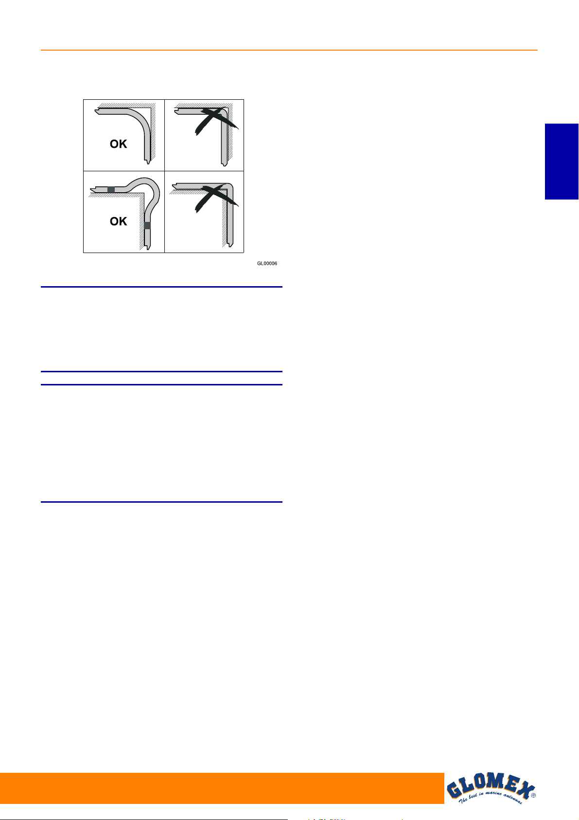
S
In order to prevent that current leakage or charge
build-up may damage the electronic components of
the antenna, make sure there is an efficient
grounding system.
S
Pay attention not to bend the coaxial cables at a
right angle; the bending angle must always be
higher than 120°.
WARNING
WARNING
WARNING
56
www.glomex.it
Page 17
NOTA: Do not cut the connectors of the coaxial
Fig. 17
cables (the operation would not be guaranteed any
more) and always use the original GLOMEX cables
supplied, even with inappropriate dimensions (too
long). Do not use different cables, as it would
jeopardize the operation of the equipment.
SATURN MARS RHINE
ENGLISH
S
If the control unit shows the error message ERR1,
there is no communication between the antenna
and the control unit.
It is therefore necessary to check that the connection cable between antenna and control unit is correctly fastened and is not interrupted or shortcircuited.
WARNING
www.glomex.it
57
Page 18

SATURN MARS RHINE
Fig. 18
Backside of the control units
Receiver
Receiver
Receiver
Receiver
Isolated 75 ohm charge or maximum another
3 multiswitches and, on the last one, the isolated 75 ohm charge.
Isolated 75 ohm charge
Receiver
Receiver
Receiver
Receiver
5. For models V9104S2U, V9104SKEWS2U,
V9804S2U, V9804SKEWS2U and R9804S2U
which provide for the presence of the multiswitch, connect the cables by following the indications given in Fig. 18.
ENGLISH
58
www.glomex.it
Page 19

6. For model R9804SERS2U connect the cables
Fig. 19
Backside of the control units
Isolated 75 ohm charge or maximum another 3 multiswitches
and, on the last one, the isolated 75 ohm charge.
Isolated 75 ohm charge
Receiver
Receiver
Receiver
Receiver
Receiver
Receiver
Receiver
Receiver
by following the indications given in Fig. 19.
SATURN MARS RHINE
ENGLISH
www.glomex.it
59
Page 20

SATURN MARS RHINE
Fig. 20
Fig. 21
To connect the coaxial cables to VL, HL, VH and
HH sockets of the coaxial rotating joint it is necessary to remove the upper radome and to connect
the various cables to the connectors (1) available
inside the lower radome, trying to give the cables a
path that follows the curvature of the radome.
NOTA: for some models, there is a single bracket
with 4 connections instead of 2 brackets with 2
connections each.
ENGLISH
8. Connect the cables to the line amplifier (is available), to the multiswitch (if available), to the
receiver(s) (not included), as indicated in Fig. 1,
Fig. 15, Fig. 18.
7. The control unit may be fastened to a vertical
wall by means of the Vimar
®
in-built covering
frame provided together with the antenna. In
this case, drill a hole with a reciprocating saw,
using the cutting template in Fig. 22.
The control unit may be fastened also to a horizontal surface or to the roof. In this case, it is
necessary to use the 2 L-shaped brackets provided together with the antenna and fasten
them as indicated in Fig. 21.
60
www.glomex.it
Page 21

6.1 LOWER RADOME CUTTING TEMPLATE
Fig. 22
SATURN MARS RHINE
ENGLISH
www.glomex.it
61
Page 22

SATURN MARS RHINE
Fig. 23
6.2 CONTROL UNIT CUTTING TEMPLATE FOR INSTALLATION ON A VERTICAL WALL
ENGLISH
62
www.glomex.it
Page 23

6.3 SKEW CALIBRATION (MANUAL)
Fig. 24
Fig. 25
4 outputs
Satellites can transmit in linear (Europe) or circular
(USA) polarisation. GLOMEX antennas are
designed to operate with a linear or circular polarisation according to the installed LNB, depending
on the satellite whose transmission you want to
receive and on where you are positioned.
Circular polarisation does not require any calibration for the optimization of the received signal.
On the contrary, LNB operating with linear polarisation need calibrating upon installation, in order to
optimize the alignment of the LNB with the satellite
whose transmission you want to receive.
When you are at the same longitude of the satellite,
its horizontal and vertical signals are aligned with
the horizon. When the satellite is east or west of
your position, the signal of the satellite will appear
as clockwise or counterclockwise shifted. Both the
horizontal and the vertical signal will be shifted by
the same angle, and therefore they will always be
perpendicular to each other.
The degree of rotation will depend on the distance
to the east or to the west between the position of
the antenna and the position of the satellite, and on
your distance from the equator.
Once you move to an area with a longitude more
than +/- 10° from the previous position, the LNB
must be manually adjusted in order to obtain the
best possible signal.
Antennas are delivered with the LNB optimized for
an area with longitude 12° East while receiving satellite 13° East.
SATURN MARS RHINE
ENGLISH
For the adjustment of the LNB, proceed as follows:
- loosen the screws on the radome and remove the
upper radome from the base;
- loosen the four screws on the front part of the
dish and manually move it, using the parameter
of signal quality of the digital receiver in use as a
reference for correct calibration (please refer to
the receiver’s manual).
Calibration does not need to be changed any
more if the boat remains in the same area and
receives transmission from the same satellite.
Once the desired adjustment has been carried out,
tighten the screws, position the upper radome onto
its base again and tighten the fastening screws.
www.glomex.it
NOTA: the operations described above are not to
be carried out in case of antennas with automatic
SKEW adjustment!
(V9104SKEWS2U and V9804SKEWS2U)
S
While adjusting the SKEW, please make sure not
to disconnect the two sensor cables fastened to the
LNB.
WARNING
63
Page 24

SATURN MARS RHINE
EGITTO
GIORDANIA
GL00096
Fig. 26
6.4 SKEW ADJUSTMENT GRID FOR
EUROPE
To determine the values for adjusting the LNB, it is
possible to use the grid below and the relevant
table.
ENGLISH
We recommend obtaining the exact values for the
adjustment of the skew by using the (free licence)
app SMW Link (distributed by SWEDISH MICROWAVE AB) available for both iOS on the App Store
and for Android on Play Store. Select the menu
item “Antenna Alignment”.
64
www.glomex.it
Page 25

SATURN MARS RHINE
Astra 3 (23,5°E)
Turksat (42°E)
Eurobird (9°E)
Hot-Bird (13°E)
Sirius 4 (5°E)
Astra 1 (19,2°E)
Atlantic Bird 3 (5°W)
GL00249
Fig. 27
Grid position TURKSAT
42°E
ASTRA
2
28.2°E
ASTRA
3
23.5°E
ASTRA
1
19.2°E
HOTBIRD
13.0°E
SIRIUS
4.8°E
THOR
1°W
HISPASAT
30°W
ATL ANTI C
BIRD 3
5°W
A (6°W 58°N) -25° -19° -18° -14° -11° -6° -3° 14° -3
B (6°E 58°N) -20° -13° -12° -8° -4° 0° 4° 20° 4
C (18°E 58°N) -14° -6° -4° 0° 3° 8° 11° 24 11
D (30°E 58°N) -7° 1° 3° 6° 10° 14° 17° 28° 16
E (42°E 58°N) 0° 7° 10° 13° 16° 20° 23° 30° 21
F (6°W 52°N) -30° -24° -21° -18° -14° -8° -3° 17° -2
G (6°E 52°N) -24° -16° -13° -10° -5° 0° 5° 24° 6
H (18°E 52°N) -17° -8° -5° 0° 3° 9° 14° 34° 15
I (30°E 52°N) -9° 1° 4° 8° 12° 18° 21° 36° 22
J (42°E 52°N) 0° 11° 12° 17° 20° 25° 28° 22° 26
K (6°W 45°N) -36° -29° -27° -23° -18° -10° -5° 30° -4
L (6°E 45°N) -30° -20° -20° -12° -7° 0° 6° 31° 7
M (18°E 45°N) -22° -9° -8° -1° 4° 12° 18° 36° 18
N (30°E 45°N) -11° 2° 5° 10° 16° 22° 27° 40° 26
O (42°E 45°N) 0° 13° 17° 21° 25° 31° 34° 43° 34
P (6°W 38°N) -43° -35° -36° -28° -22° -13° -6° 27° -5
Q (6°E 38°N) -37° -25° -23° -16° -8° 1° 8° 36° 12
R (18°E 38°N) -27° -12° -10° -1° 6° 16° 22° 43° 23
S (30°E 38°N) -15° 2° 8° 13° 20° 28° 33° 47° 35
T (42°E 38°N) 0° 17° 23° 26° 31° 37° 41° 50° 44
U (6°W 30°N) - -44° -43° -36° -28° -18° -8° 35° -7
V (6°E 30°N) - -33° -34° -21° -11° 1° 11° 45° 17
W (18°E 30°N) - -16° -11° -1° 8° 21° 29° 52° 36
X (30°E 30°N) - 3° 10° 18° 25° 36° 41° 56° 50
Y (42°E 30°N) - 22° 28° 34° 38° 46° 49° 58° 54
ENGLISH
www.glomex.it
65
Page 26

SATURN MARS RHINE
Fig. 28
POWER ON KEY I
SIGNAL SEARCH
SOUTH SEARCH
IS IT THE SELECTED
SATELLITE?
NO
SATELLITE SEARCH
SATELLITE OK
YES
CALIBRATION
SATELLITE FOUND
SATELLITE CHECK AND
IDENTIFICATION
7. USE
Flow chart
ENGLISH
66
www.glomex.it
Page 27

SATURN MARS RHINE
Fig. 29
A. Power on key
B. Two-line alphabetic display:
• B1 (first line): name of the satellite to be
received
• B2 (second line): running function
C. Key for satellite selection and activation/
deactivation of energy saving system.
1. Make sure that the antenna has a clear view of
the sky in order to receive satellite signals.
2. Turn on the receiver and the TV set. For details
about the use of the receiver and the TV set,
please refer to the relevant user manuals provided by the manufacturers.
3. To turn on the control unit, position the key (A)
to I: the antenna automatically communicates to
the control unit when it is ready and starts
searching for the selected satellite taking min.
20 seconds up to a max. of 2 minutes, according to the boat’s movement.
4. LANGUAGE SELECTION: upon start-up, while
GLOMEX appears on the display, it is possible
to select the desired language (among Italian,
English, French, Spanish and German) by
repeatedly pressing key (C). To confirm selection, just turn off and on again the control unit
by means of key (A).
5. SELECTION OF THE SATELLITE TO BE
SEARCHED: repeatedly press key (C) for satellite selection, until the alphanumeric display in
its first line (B1) corresponds to the desired
choice.
The following satellites are the ones which can
be received with the device:
- ASTRA2 28.2°E
- ASTRA3 23.5°E
- ASTRA1 19.2°E
-HOTBIRD 13°E
- EUROBIRD 9°E
- SIRIUS 4.8°E
- THOR 1°W
- HISPASAT 30°W
After selecting the desired satellite, the antenna
immediately starts searching for the signal, indicating it in the second line of the display (B2).
6. SATELLITE SIGNAL SEARCH AND
TRACKING: when the antenna has found the
satellite signal, this is verified and, in case of
success, the display shows “sat ok” (B2).
Sometimes it may happen that an antenna first
receives a different satellite from the selected
one (depending on position, transmitted signal
strength and weather conditions). In this case,
the NIT system check is negative and the
antenna immediately starts searching for the
selected satellite, taking into account the position of the satellite just found. The control unit
saves the last satellite position selected on it
and, the next time it is turned on, it starts
searching for this last satellite position. When
the antenna is tracking, you can watch TV pro-
grammes and listen to the RADIO using a
receiver and a TV set (not provided).
7. ENERGY SAVING FUNCTION: when the boat
is moored and the movements are minimal, you
can activate the energy saving function that will
not only minimize electric consumption, but also
eliminate any noise coming from the antenna.
To enable this function, press key (C) once for
satellite selection (the display indicates the status - enabled or disabled). To change status,
press key (C) again. When the function is enabled, after about 2 minutes that the boat did not
move, the antenna stops in the position where
signal reception from the satellite is maximum.
A level decrease of the received signal or a total
shift of the boat of 6° in two minutes “wake the
antenna up” in order that it recovers the maximum receivable signal level.
ENGLISH
www.glomex.it
67
Page 28

SATURN MARS RHINE
CAPTION OF CONTROL UNIT FUNCTIONS
Start-up: when turning on the control unit, the dis-
play shows
‘ GLOMEX V9804S2U ’
‘ DVB-S2 VX.XXX ’
VX.XXX = SW VERSION
ANTENNA INIT: in this phase, the antenna posi-
tions itself for calibration;
CALIBRATION: calibration phase of the gyro-
ENGLISH
scopes;
SOUTH SEARCH: rotation of the azimuth axis
which positions the antenna southbound;
SAT SEARCH: satellite search; unless the user
intervenes, the antenna automatically starts
searching for the last satellite received;
FOUND SAT: writing that appears on the display
when the antenna finds a satellite signal before the
NIT system check is run.
LOST SIGNAL: it appears in case the signal is lost;
ANT. STANDBY: it appears when the antenna
manages to receive the satellite signal and the boat
remains motionless for a certain period of time. In
this situation, the antenna stops on the maximum
value of the received signal, reducing operating
noise and energy consumption;
NEXT SAT SEARCH: message displayed when
the antenna passes from one satellite to another,
when the first satellite received does not match the
one selected;
SAT VERIFICATION: message that appears when
the satellite is received during the NIT system verification phase;
WARNING ERR 1: there is no communication
between the antenna and the control unit.
SAT OK: it indicates that the selected satellite has
been correctly hooked up and verified.
READY FOR UPDATE - INSERT USB KEY: awaiting the USB memory containing the upgrade file.
CHECK UPGRADE FILE: check of the upgrade
file.
UPDATING: upgrade in progress.
UPGRADE SUCCESSFUL: upgrade executed
successfully.
68
www.glomex.it
Page 29

8. TIPS FOR CORRECT USAGE
GL00045
Fig. 30
Fig. 31
GLOMEX recommends observing the following
indications for a correct use of the equipment.
- The receiver must be activated before receiving
the satellite programmes.
- Keep the radome always mounted on the
antenna. Its task is to protect all inner (fixed and
moving) parts from wind, rain and dust.
- Do not lean against and/or sit on the antenna!
- Pay attention not to spill liquids of any kind into
the antenna.
- The radome should be cleaned periodically.
Dust or dirt accumulated on the radome could
affect the satellite signal receipt. Clean the
radome with a cloth damped with water. DO
NOT USE BRUSHES, ABRASIVE PRODUCTS,
DETERGENTS OR ALCOHOL-BASED LIQUIDS.
- Do not paint the surface of the radome! This
would negatively affect signal receipt.
SATURN MARS RHINE
ENGLISH
- The antenna requires a clear view of the sky to
receive satellite signals. Possible very common
signal obstructions include masts of other boats,
bridges, on-board equipment, etc. GLOMEX
antennas also do not operate inside storage
areas.
- Heavy rain or snow could temporarily interrupt
signal receipt from the satellite.
- The boat must be within the coverage area of
the selected satellite to receive the desired signal. Please refer to the satellite coverage footprints on page 71.
S
Bad weather conditions affect the quality of the signal and reduce image quality!
- At the end of its life, do not scatter the antenna
or its components into the environment, but take
advantage of specialized waste disposal agencies.
WARNING
www.glomex.it
69
Page 30

SATURN MARS RHINE
8.1 FOOTPRINTS: SATELLITE
TRANSMISSION AREAS
Satellite television is one of the few means which
allow receiving information in any part of the world
within the coverage area of the satellite you wish to
receive.
The signal transmitted by the satellite generally has
a wide coverage area, as shown in the purely indicative footprints on the following page, and thus
ENGLISH
guarantees you can watch the same TV programmes in various areas.
However, it is important to remember that ground
obstacles are the main causes of satellite antenna
malfunction.
Ground obstacles include all bodies which could be
located between satellite and antenna, such as
masts of other boats, bridges, on-board equipment,
etc.
The signal transmitted by the satellite is also
affected by weather conditions (storm clouds or ice
clouds).
The footprints show the satellite coverage areas on
the Earth by using the GLOMEX satellite antennas.
S
In case of bad weather, signals will be weaker;
therefore, the image quality could be reduced, up
to completely fading away. It is also very important
to make sure, upon purchase, that the dimensions
of the satellite antenna are the most appropriate
ones to receive the signal in the areas where you
spend your holiday. Footprints are indicative and
referred to the satellite with the strongest E.I.R.P.
(Equivalent Isotropic Radiated Power).
WARNING
70
www.glomex.it
Page 31

SATURN MARS RHINE
GL00258
ATLANTIC BIRD 3 (5°W)
Fig. 32
ENGLISH
www.glomex.it
71
Page 32

SATURN MARS RHINE
9. MAINTENANCE
9.1 PREVENTIVE MAINTENANCE
GLOMEX antennas require minimum preventive
maintenance.
Observing the following instructions is sufficient to
maintain a high equipment performance.
Monthly checks
- Wash the radome surface with a cloth damped
ENGLISH
with fresh water; do not direct pressurized water
jets onto the radome.
S
Do not use brushes, abrasive products, detergents
or alcohol-based liquids.
Yearly checks
- Check the outer conditions of the radome. Clean
from dust and dirt if necessary.
Checks before any long cruise
- Check that the antenna is correctly fastened.
WARNING
Should you have problems with the operation or in
case you need technical support, first of all contact
the authorized Retailer. Keep at hand the serial
number of your antenna (on page 2 in this manual)
and a list with the failure symptoms. Should no
Retailer be available, contact the GLOMEX Service
Centre (see section “Technical Support”).
S
You will be asked the serial number of your
antenna during any service or troubleshooting
phone call. The serial number is found on page 2 of
the user manual of your antenna (see page 44 for
serial number indications).
S
Conserve the installation and user manual with
care, as it contains the serial number of your
antenna!
WARNING
WARNING
S
Before carrying out any maintenance or cleaning
operation, or after each use, ALWAYS turn off the
antenna by means of the switch located on the
control unit or from the on-board control panel.
9.2 SPARE PARTS
The following table lists the codes of the components which can be supplied as spare parts directly
by the Retailer.
Lower radome SATURN V9104S2U V9104S2U-LR
Upper radome SATURN V9104S2U V9104S2U-UR
Lower radome SATURN V9104SKEWS2U V9104SKEWS2U-LR
Upper radome SATURN V9104SKEWS2U V9104SKEWS2U-UR
Lower radome MARS V9804S2U V9804S2U-LR
Upper radome MARS V9804S2U V9804S2U-UR
Lower radome MARS V9804SKEWS2U V9804SKEWS2U-LR
Upper radome MARS V9804SKEWS2U V9804SKEWS2U-UR
Lower radome RHINE R9804S2U R9804S2U-LR
Upper radome RHINE R9804S2U R9804S2U-UR
Lower radome RHINE R9804SERS2U R9804SERS2U-LR
Upper radome RHINE R9804SERS2U R9804SERS2U-UR
DANGER
Component GLOMEX code
72
www.glomex.it
Page 33

9.3 SOFTWARE UPDATE BY FLASH USB
The SD card must be inserted into the USB port
located on the control unit front side.
The USB memory used for updating must be formatted in FAT32, cluster size 4096 bytes (4k).
It is therefore necessary to copy the provided file
update-XXXXX.hex onto the USB memory, proceeding as follows:
- Turn on the control unit and press the SAT
SELECT button while BOOT is displayed.
SATURN MARS RHINE
ENGLISH
- Wait, the upgrade procedure takes about 30 seconds.
- The message READY FOR UPDATE INSERT
USB KEY will be displayed.
- Insert the USB flash formatted in FAT32 containing the file update-XXXXX.hex.
- The control unit will check the integrity of the
upgrade file displaying CHECK UPGRADE FILE.
- Once the upgrade is completed, UPGRADE
SUCCESSFUL will be displayed.
- Turn off the control unit and remove the USB
memory.
S
In case of repeated failures in the software update
procedure, please contact the GLOMEX Service
Centre.
WARNING
www.glomex.it
NOTA: it is possible to download the necessary
software updating file from the Glomex website
(www.glomex.it) in section “Technical Support Download Area”.
73
Page 34

SATURN MARS RHINE
Fig. 33
USB UPGRADE
INSERT USB MEMORY
(ready for update insert
usb key)
CHECK UPGRADE
FILE
(check upgrade file)
NO
SOFTWARE
UPGRADE (updating)
YES
UPDATE
COMPLETED
(upgrade succesfull)
TURN OFF THE
CONTROL UNIT AND
REMOVE THE USB
MEMORY
NO
YES
CHECK THE UPGRADE
FILE ON THE USB
MEMORY
TURN OFF THE
CONTROL UNIT
PRESS SAT SELECT
WHILE THE BOOT
MESSAGE IS
DISPLAYED
TURN ON THE
CONTROL UNIT
Flow chart
ENGLISH
74
www.glomex.it
Page 35

10. TROUBLESHOOTING
SATURN MARS RHINE
When a malfunction of your satellite system occurs,
it is very important to make a rapid check to understand the nature of the malfunction and, if possible,
to find a remedy.
To analyze a malfunction, it is appropriate to carry
out the following verifications:
- the malfunction has been generated through
human mistake;
- the malfunction is due to a weather problem;
- the malfunction is due to a failure of the equipment itself or it is caused by an anomaly of
another external appliance, but in some ways
connected to the equipment;
- in which phase the malfunction occurs: upon
start-up, during normal operation, upon shutdown;
- the malfunction is repeated; if so, according to
what criteria;
- what the malfunction determine from a functional
point of view;
Anomaly Cause Remedy
1. The control unit shows the
error message ERR1
2. The antenna does not operate - wrong power supply cable
3. No status message on the
decoder
4. No image on the TV - the receiver is off - turn off the control unit, turn on
- no connection between control
unit and antenna
connection
- short-circuited coaxial cable - check the correct mounting of
- proper failure - contact the Service Centre
- the coaxial cable has loosened
or has disconnected from the
antenna
- inner failure - contact the Service Centre
- the satellite receiver is not
installed correctly
- alternating current fluctuations - refer to the user manual of the
- the TV set is off or has not
been tuned to AV
- wrong cable connection on the
receiver
- the channel list is not up-todate
- whether the malfunction produces signals (light
signals) and/or anomalous noise (such as hissing, buzzing, etc.) and/or anomalous odours
(smell of burning) or not;
- the malfunction interferes with the operation of
other appliances;
- the malfunction is an apparent failure (i.e. it disappears, for example, by turning off and then on
again the equipment).
The better you are able to answer the above-mentioned questions, the deeper the malfunction analysis will be.
The following table analyzes the most probable
causes which can lead to malfunctions of your
GLOMEX satellite antenna. For any analyzed possible cause, a corrective measure is proposed, to efficiently solve, as much as possible, the trouble.
- check that the connection
cable between antenna and
control unit is correctly fastened and is not interrupted or
short-circuited
- check the polarity on the
power supply line
the coaxial cables
- check the connection of the
coaxial cables
- check the receiver connection
receiver for support
the receiver and then turn on
the control unit again
- turn on the TV set and tune to
AV channel
- check that the SCART socket
between the TV set and the
receiver is installed correctly
- carry out the automatic channel search in the receiver
menu
ENGLISH
www.glomex.it
75
Page 36

SATURN MARS RHINE
5. Intermittent images for short
periods
ENGLISH
6. The equipment does not find
the satellite
7. Disturbed images - failure of the receiver - refer to the user manual of the
- the satellite signals are
obstructed by masts of other
boats, bridges, on-board
equipment, etc.
- the boat is at the boundary of
the coverage area
- bad weather conditions
- wrong SKEW adjustment - adjust the SKEW by following
- the satellite signals are
obstructed by masts of other
boats, bridges, on-board
equipment, etc.
- the boat is outside the signal
coverage area
- the boat is heaving within the
first 60 seconds after turning
on the equipment
- bad weather conditions
- inner failure - contact the Service Centre
- the satellite signals are
obstructed by masts of other
boats, bridges, on-board
equipment, etc.
- the equipment software is not
up to date
- wrong SKEW adjustment - adjust the SKEW by following
- parameters in satellite communication have changed
- move the boat to allow an
unobstructed view for the
antenna
- go back within the coverage
area; refer to the footprints of
the coverage areas on page
71 in this manual
the instructions on page 63
- move the boat to allow an
unobstructed view for the
antenna or correctly position
the antenna on the boat
- go back within the coverage
area; refer to the footprints of
the coverage areas on page
71 in this manual
- turn off the equipment for 10
seconds, turn it on again and
make sure that the boat is still
or moves in a straight line during the first 60 seconds after
being turned on
- move the boat to allow an
unobstructed view for the
antenna
- please contact the Service
Centre to ask for software
update
the instructions on page 63
- please contact the Service
Centre to ask for software
update
receiver for support, spare
parts and warranty conditions.
76
www.glomex.it
Page 37

SATURN MARS RHINE
8. Confused, incomplete and
obstructed images
9. The decoder blocks - alternating current fluctuations - refer to the user manual of the
10. The equipment operates with
still boat but not with moving
boat
For further information, please address to the
GLOMEX Service Centre (see section “Technical
Support”).
- condensate or rain on the
radome, which can disturb the
signal
- bad weather conditions - periodically apply a liquid
- wrong SKEW adjustment - adjust the SKEW by following
- the satellite signal is
obstructed
- failure in the gyroscope system
- remove the condensate
deposits from the radome with
a fresh water jet (not under
pressure)
detergent suitable for dishes
(no alcohol-based detergent)
to the radome surface and let
dry up
the instructions on page 63
receiver for support
- move away from possible
obstacles obstructing the satellite signal
- contact the Service Centre
ENGLISH
11. RESHIPPING
Should you need to return the antenna to
GLOMEX, place it in a box, possibly the original
one, making sure it is well packaged and that the
upper and lower side are well recognizable.
In order to prevent any damage to the antenna during transport, it is necessary to send it inside the
original radome (upper and lower) and fasten it to
the lower radome using 4 M8x10 screws.
Together with the antenna, please also send the
control unit, so that a verification of the whole system is possible.
NOTA: GLOMEX will not be liable for possible
damage occurred during transport due to incorrect
packaging.
S
Do not ship the antenna to GLOMEX for repairs
without having received a corresponding authorization to return the material (RMA), as reported in the
general warranty/support conditions.
WARNING
www.glomex.it
77
Page 38

SATURN MARS RHINE
12. TECHNICAL SPECIFICATIONS
SATURN4 V9104S2U
Antenna dish diameter 47 cm
Radome dimension 50 x 56 cm
Antenna weight 13.0 kg
Tracking rate 50° sec
Antenna gain 35 dB - 12 GHz
ENGLISH
Dish type
Polarization Linear (H + V)
LNB
Radome type UV resistant
Power requirements 12/24 Vdc (1.5 A/h)
Operating temperature
range
Azimuth turn range Unlimited
Full elevation range 5° - 90°
Type of stabilization
Satellite identification
Min. EIRP 49 dBW
Future upgrade ready Yes
Decoder output
Autoskew NO
Control unit
PRIME FOCUS
+
HPD
10.7 GHz / 12.75
GHz
-20 °C +55 °C
Gyro on 2 axis +3°
axis by interpolation
NIT (Network
identification table)
4 outputs to the
multiswitch
(maximum 16
outputs)
8 satellites loaded:
see page 67
SATURN4 V9104SKEWS2U
Antenna dish diameter 47 cm
Radome dimension 50 x 56 cm
Antenna weight 13.0 kg
Tracking rate 50° sec
Antenna gain 35 dB - 12 GHz
PRIME FOCUS
Dish type
Polarization Linear (H + V)
LNB
Radome type UV resistant
Power requirements 12/24 Vdc (1.5 A/h)
Operating temperature
range
Azimuth turn range Unlimited
Full elevation range 5° - 90°
Type of stabilization
Satellite identification
Min. EIRP 49 dBW
Future upgrade ready Yes
Decoder output
Autoskew YES
Control unit
10.7 GHz / 12.75
-20 °C +55 °C
Gyro on 2 axis +3°
axis by interpolation
identification table)
4 outputs to the
(maximum 16
8 satellites loaded:
+
HPD
GHz
NIT (Network
multiswitch
outputs)
see page 67
78
www.glomex.it
Page 39

SATURN MARS RHINE
MARS4 V9804S2U
Antenna dish diameter 60 cm
Radome dimension 66 x 66 cm
Antenna weight 15.5 kg
Tracking rate 50° sec
Antenna gain 36.5 dB - 12 GHz
PRIME FOCUS
Dish type
Polarization Linear (H + V)
LNB
Radome type UV resistant
Power requirements 12/24 Vdc (1.5 A/h)
Operating temperature
range
Azimuth turn range Unlimited
Full elevation range 5° - 90°
Type of stabilization
Satellite identification
Min. EIRP 47 dBW
Future upgrade ready Yes
Decoder output
Autoskew NO
Control unit
10.7 GHz / 12.75
-20 °C +55 °C
Gyro on 2 axis +3°
axis by interpolation
identification table)
4 outputs to the
(maximum 16
8 satellites loaded:
+
HPD
GHz
NIT (Network
multiswitch
outputs)
see page 67
MARS4 V9804SKEWS2U
Antenna dish diameter 60 cm
Radome dimension 66 x 66 cm
Antenna weight 15.5 kg
Tracking rate 50° sec
Antenna gain 36.5 dB - 12 GHz
PRIME FOCUS
Dish type
Polarization Linear (H + V)
LNB
Radome type UV resistant
Power requirements 12/24 Vdc (1.5 A/h)
Operating temperature
range
Azimuth turn range Unlimited
Full elevation range 5° - 90°
Type of stabilization
Satellite identification
Min. EIRP 47 dBW
Future upgrade ready Yes
Decoder output
Autoskew YES
Control unit
10.7 GHz / 12.75
-20 °C +55 °C
Gyro on 2 axis +3°
axis by interpolation
identification table)
4 outputs to the
(maximum 16
8 satellites loaded:
+
HPD
GHz
NIT (Network
multiswitch
outputs)
see page 67
ENGLISH
www.glomex.it
79
Page 40

SATURN MARS RHINE
80
www.glomex.it
ENGLISH
13. TECHNICAL SUPPORT
In case technical support is needed, please contact
the GLOMEX SERVICE CENTRE:
Glomex Divisione Marine
Via Faentina 165/G
48124 Ravenna (Italy)
Tel. +39 0544 1935911 (only from Italy)
Fax +39 0544 500420
Email: service@glomex.it
RHINE R9804S2U
Antenna dish diameter 60 cm
Radome dimension 66 x 66 cm
Antenna weight 15.5 kg
Tracking rate 25° sec
Antenna gain 36.5 dB - 12 GHz
Dish type
PRIME FOCUS
+
HPD
Polarization Linear (H + V)
LNB
10.7 GHz / 12.75
GHz
Radome type UV resistant
Power requirements 12/24 Vdc (1.5 A/h)
Operating temperature
range
-20 °C +55 °C
Azimuth turn range Unlimited
Full elevation range 5° - 90°
Type of stabilization
Gyro on 2 axis +3°
axis by interpolation
Satellite identification
NIT (Network
identification table)
Min. EIRP 47 dBW
Future upgrade ready Yes
Decoder output
4 outputs to the
multiswitch
(maximum 16
outputs)
Autoskew NO
Control unit
8 satellites loaded:
see page 67
RHINE R9804SERS2U
Antenna dish diameter 60 cm
Radome dimension 66 x 66 cm
Antenna weight 15.5 kg
Tracking rate 25° sec
Antenna gain 36.5 dB - 12 GHz
Dish type
PRIME FOCUS
+
HPD
Polarization Linear (H + V)
LNB
10.7 GHz / 12.75
GHz
Radome type UV resistant
Power requirements 12/24 Vdc (1.5 A/h)
Operating temperature
range
-20 °C +55 °C
Azimuth turn range Unlimited
Full elevation range 5° - 90°
Type of stabilization
Gyro on 2 axis +3°
axis by interpolation
Satellite identification
NIT (Network
identification table)
Min. EIRP 47 dBW
Future upgrade ready Yes
Decoder output
4 outputs to the
multiswitch
(maximum 16
outputs)
Autoskew NO
Control unit
8 satellites loaded:
see page 67
+39 199 30 11 30
 Loading...