

Page 1

________________________________________________________________________________
MARINE SATELLITEN TV ANTENNEN
MARINE SATELLITE TV ANTENNAS
VENUS
SATURN
MARS
INSTALLATION HANDBUCH
V9801 V9800 V9804
INSTALLATION MANUAL
BETRIEBSANLEITUNG
V9000
V9100 V9103 V9104
USER MANUAL
Vorläufige Version - Provisional Version
______________________________________ ____________________________________
1
Page 2

________________________________________________________________________________
______________________________________ ____________________________________
2
Page 3

________________________________________________________________________________
INHALT – CONTENTS
Einführung – introductory information 4
Grundsätzliches - Letter to the user 4
Seriennummer & Modell - Serial Number and Model 4
Gewährleistung – Warranty 4
Sicherheitsempfehlungen – Safety recommendations 6
Wiederkehrende Kontrolle – Periodical check 6
Wartung – Maintenance 6
Installation der Kabel– Installing cables 7
Reparaturen – Repairs 7
Reinigung – Cleaning 8
Lackierung – Paint 8
Abfallentsorgung – Dispose in the environment 8
Versandinformationen – delivery information 9
Lieferumfang (Modell VENUS 9000) - contents ( model VENUS V9000) 10
Lieferumfang (Modell SATURN V9100 & V9103) - Contents (model SATURN V9100 & V9103) 11
Lieferumfang (Modell MARS V9801 & V9800) Contents V9100 (model MARS V9801 & V9800) 12
Installation der Antenne – installation of antenna 13
Montageort – Locations 14
Vorbereitung der Antenne - How to prepare the antenna 14
Anschluss des Koaxkabel in der Antenne – connection of coaxial cable inside the antenna 14
Montage der Antenne - How to mount the antenna 15
Koaxialverkabelung der Antenne - Wiring the coaxial cable 17
Montage des Kontrollmoduls – installing the underdeck control unit 17
Anschluss des Konrollmoduls V9000/V9100/V9801- connection of Control Unit 18
Anschluss des Empfängers - Where to connect the Receiver 18
Montage der Kontrolleinheit - How to mount the Control Unit 18
Anschluss der Stromversorgung – connecting the power supply 18
Anschluss des Konrollmoduls V9103/V9800- connection of the Control Unit V9103/V9800 20
Betriebsanleitung – user manual 21
Einschalten– Switching on 22
Auswahl der Sprache – Language selection
Auswahl des Satelliten – Selecting the satellite to search
Positionen von Radio- & TV-Satelliten – TV- & Radio-satellite positions 24
Suchen & verfolgen des Satellitensignales - Satellite signal search and tracking 25
Energiesparfunktion – Energy saving function 25
Funktion der Kontrolleinheit – control unit function 26
Tilt Kalibrierung – skew calibration 27
Technische Daten – Specifications 30
______________________________________ ____________________________________
3
Page 4

________________________________________________________________________________
1
. EINLEITUNG
1.
INTRODUCTION
1.1 GRUNDSÄTZLICHES
Wir von GLOMEX danken Ihnen für den Kauf eines
unserer Produkte. Diese Antenne ist für den Betrieb auf Motorbooten einer Mindestlänge von 7
Metern ausgelegt.
Diese Handbuch informiert Sie über Installation &
Betrieb der Antenne.
1.2 IDENTIFIKATION DER ANTENNE
Bitte führen Sie unbedingt bei allen Ihre Antenne
betreffenden Kontakten mit Glomex oder einem
autorisierten Servicecenter die Serien-& Modell-
nummer auf der 2. Seite dieses Handbuches an.
1.3 GEWÄHRLEISTUNG
Glomex garantiert die Satelliten-TV-Antennen
V9000 Venus, V9100, V9103 Saturn & V9801,
V9800 Mars für einen Zeitraum von 36 Monaten
ab dem Versanddatum gegen Defekte.
Mit Garantie ist Reparatur oder Ersatz von Ware
gemeint, die zum Zeitpunkt des Verkaufs Produktionsdefekte aufweist.
Im Falle eines Produktionsfehlers hat der Kunde
Anspruch auf Reparatur oder Ersatz der fehlerhaften Ware ohne Berechnung.
al ripristino, senza spese alcune, del bene.
1.1 LETTER TO THE USER
GLOMEX would like to thank you for having purchased one its products.
This satellite antenna is manufactured and designed for installation on motorboats of at least 7
meters.
This manual provides all the information you require for a proper installation and use of the Antenna.
1.2 SERIAL NUMBER AND MODEL
When calling Glomex or an authorized Service
Centre remember to provide the serial number
and model shown on the second page of the
user’s manual and/or on the box containing the
electronic P.C.B. inside the antenna, on the dc-dc
converter, on the control unit, on the box
.
1.3 WARRANTY
Glomex guarantees the satellite antennas series
V9000 Venus, V9100, V9103 Saturn and V9801,
V9800 Mars against conformity defects for a period of 36 (thirty-six) months from the shipment
date.
Warranty is intended as the repairing or replacement of the equipment showing conformity defects when the sales contract is drawn up.
Diese Garantie gilt nur bei Vorlage eines gültigen
Kaufbeleges.
Schadhafte Ware ist zur Reparaturstelle oder zum
Händler zu retournieren, der sie an
Glomex S.r.l. - Via Faentina 165g 48100,
Ravenna (Italia)
gemeinsam mit allem beim Verkauf mitgeliefertem Zubehör zurückschickt.
In case of conformity defects, the customer is entitled to the repair or replace of the good with no
charges.
The warranty is valid only if the product comes
with a valid proof of purchase (official receipt or invoice).
The not conforming product must be sent back to
a technical assistance centre or authorized retailer, who will provide to forward it to:
Glomex S.r.l. - Via Faentina 165g 48100,
Ravenna (Italy)
along with all the accessories supplied at
the purchasing.
______________________________________ ____________________________________
4
Page 5

________________________________________________________________________________
Die Seriennummer, die auf der Abdeckung der
Elektronikeinheit innen im Antennenradom, auf
der Kontrolleinheit auf dem Radom, auf dem
Handbuch & auf der Antennenschachtel steht darf
weder gelöscht noch unleserlich gemacht werden,
andernfalls erlischt die Garantie.
Die Gewährleistung erstreckt sich nicht auf Schäden, die durch Unachtsamkeit, normale Abnützung, Nachlässigkeit des Benutzers, Unfälle oder
durch nicht der Montageanleitung entsprechende
Installation verursacht wurden, sowie bei an Produkt oder Seriennummer vorgenommen Veränderungen.
Weiters erstreckt sich die Gewährleistung nicht
auf durch falsche Versorgungsspannungen, Spannungsschwankungen, durch Leckagen, Feuer, Blitzentladungen, Überspannungen oder andere nicht
mit der Ausrüstung in Zusammenhang stehende
Phänomene sowie durch induktive oder elektrostatische Entladungen verursachte Schäden.
Alle der Abnutzung unterliegenden Teile wie Verbindungskabel, Antriebsriemen, Verbinder, äußere
Teile & Kunststoffhalterungen unterliegen einer
einjährigen Garantie.
The serial number, written on the box containing
the electronic unit inside the antenna’s radome,
on the control unit, on the antenna’s radome, on
the installation manual and on the box containing
the antenna must neither be erased nor made illegible, or the warranty will be voided.
The warranty does not apply in case of damages
due to carelessness, utilization or installation not
consistent with the supplied instructions, tampering, product or serial numbers modifications,
damages due to accidental causes or buyer’s negligence.
Moreover, warranty does not apply in case of
damages consequent to connections of the equipment to different voltages than indicated or to
sudden tension variations of the network the
equipment is connected to, as well as in case of
damages caused by leakage, fire, discharges due
to lightening, overvoltages, other phenomena notrelated to the equipment or inductive/electrostatic
discharges.
The parts subject to wear consequent to employment, connection cables, drive belts, connectors,
external parts and plastic mounts are covered by
a one-year period warranty.
Regelmäßige Überprüfung, Software-Updates,
Produkteinstellungen & Wartungsarbeiten fallen
nicht unter Garantie oder Gewährleistung
Nach Ablauf der Garantieperiode werden dem
Kunden Arbeitszeit, Ersatzteilkosten & Frachtspesen verrechnet.
Garantieersatz wird ausschließlich nach Zustimmung der Glomex-Qualitätsabteilung
geleistet.
Im Falle von Kontroversen ist Gerichtsstand ausschließlich Ravenna (Italien)
Die Gewährleistung erfolgt durch:
Glomex S.r.l.
Via Faentina 165/G
48100 Ravenna (Italien)
Periodical checks, software updates, product settings and maintenance are not included in the
warranty.
After the expiration of the warranty period, the
technical assistance activities will be carried out
charging the customer for the replaced parts, the
cost of labour and freight charges, according to
current rates.
The equipment will be replaced in warranty
only and exclusively after Glomex quality
department approval.
Should any dispute rise, the place of jurisdiction
will be exclusively Ravenna (Italy).
The warranty is carried out by:
Glomex S.r.l.
Via Faentina 165/G
48100 Ravenna (Italy)
______________________________________ ____________________________________
5
Page 6
________________________________________________________________________________
2.SICHERHEITSEMPFEHLUNGEN
Die Montage der Antennen
muss von einem autorisierten
oder von Glomex geschulten
Techniker durchgeführt werden.
Spannungsversorgung: schließen Sie die Antenne an eine
Stromversorgung von 10 – 30
Volt an einem unbenutzten
Schalter (min. 5A) an. Vergewisserns Sie sich von der Festigkeit & Stabilität des gewünschten Montageortes der
Antenne.
2.1 REGELMÄSSIGE
KONTROLLE
überprüfen Sie von Zeit zu
Zeit, dass alle Befestigungsmuttern gut angezogen sind.
2.SAFETY RECOMMENDATIONS
Your satellite antenna must
be installed by an Authorised
Technician or a Technician
who has been trained by
Glomex. Connect the antenna
power supply (10-30Volt) to
an unused switch on board
your vessel (min 5A).
Check that the mount (on
which you will install the antenna) is stable and sturdy
enough to support the weight
of the antenna.
2.1 PERIODICAL
CHECK
Periodically check that the
nuts are well tightened.
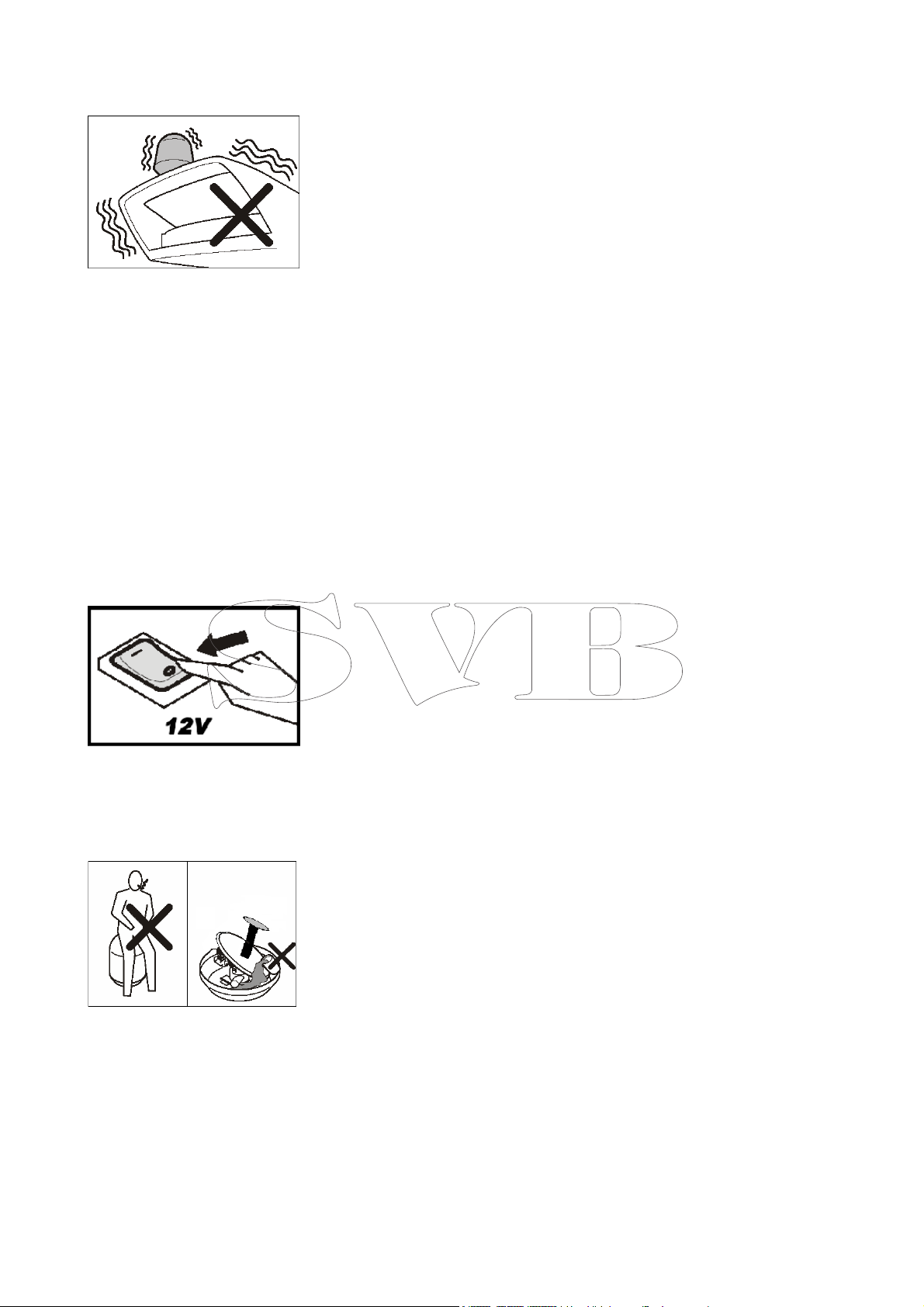
2.2 WARTUNG
Schalten Sie vor allen Wartungsarbeiten an der Antenne
IMMER deren Stromversorgung ab.
Setzen oder lehnen Sie sich
nicht an die Antenne.
Achten Sie darauf keine wie
immer gearteten Flüssigkeiten
in die Antenne zu schütten.
2.2 MAINTENANCE
Before carrying out any maintenance or cleaning and after
using the antenna, ALWAYS
turn it off from the switch to
which it is connected.
Do not lean against or sit on
the antenna.
Do not spill liquids of any kind
into the antenna.
______________________________________ ____________________________________
6
Page 7
________________________________________________________________________________
WICHTIG! Empfangs- & Bildstörungen können manchmal
durch das Fehlen eines wirksamen Erdungssystems, mit dem
alle elektronischen Ausrüstungsgegenstände des Bootes
verbunden sind, verursacht
werden. Sollte ein solches Erdungssystem nicht vorhanden
sein so installieren Sie eines &
schließen Sie alle elektronischen Ausrüstungsgegenstände, die störende Einflüsse ausüben könnten an.
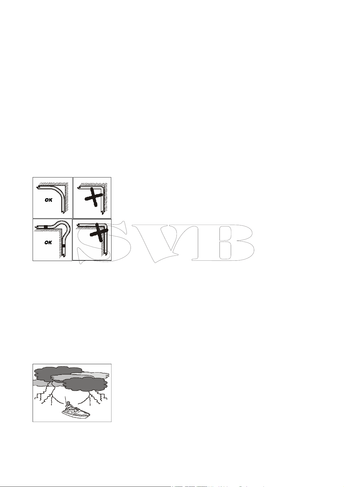
2.3 INSTALLATION DER
KABEL
Knicken Sie die Kabel nicht im
rechten Winkel ab, Mindestverlegewinkel 120°
IMPORTANT!
Sometimes reception and
viewing interference may be
due to the fact that the boat
does not have an efficient
earthing system. Ensure that
the boat has an efficient
earthing system to which all
the electronic appliances and
equipment are connected. If
not, proceed at user’s expenses to install ground plates
and connect them to all the
electronic equipment generating interference.
2.3 INSTALLING
CABLES
Do not bend the cables into a
right angle (at least 120 degree)
2.4 REPARATUREN
Kontaktieren Sie für Wartungs- oder Reparaturarbeiten Ihren Glomex Vertreter & verwenden Sie nur
Original GLOMEX Ersatzteile.
WICHTIG
Wetter kann die Empfangsqualität beeinflussen.
2.4 REPAIRS
For repairs, maintenance
or replacements please call
your Area Distributor requesting the use of original GLOMEX spare parts
only.
IMPORTANT!
Weather conditions affect the
quality of the signal
______________________________________ ____________________________________
7
Page 8
________________________________________________________________________________
2.7 ABFALLENTSORGUNG
Entsorgen Sie Ihre Antenne
nach Beendigung ihrer Lebensdauer umweltgerecht und
den Vorschriften entsprechen.
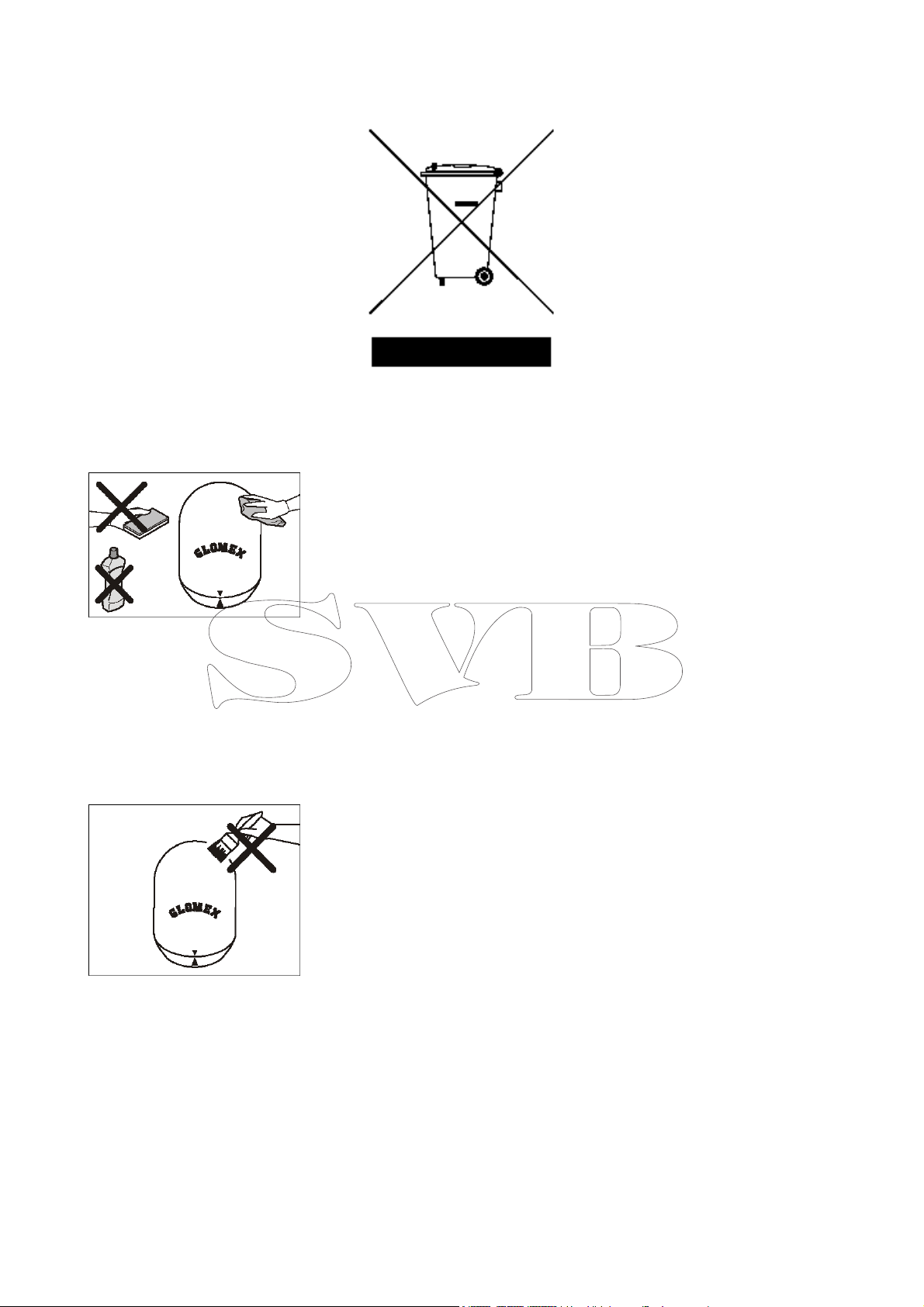
2.5 REINIGUNG
Halten Sie die Antennenabdeckung immer sauber um einen
guten Empfang zu gewährleisten.
Reinigen Sie dies mit einem
feuchten Tuch & Wasser.
VERWENDEN SIE WEDER
BÜRSTEN, SCHEUER-ODER
REINIGUNGSMITTEL
NOCH ALKOHOL.
2.6 LACKIERUNG
LACKIEREN SIE DIE
ANTENNENABDEKKUNG NICHT, DIES
BEHINDERT DEN EMPFANG.
2.5 CLEANING
To ensure good signal reception, always keep the radome
clean.
Clean with a cloth damped
with water.
DO NOT BRUSH OR
SCOUR WITH ABRASIVE
SUBSTANCES, DETERGENTS OR ALCOHOL
BASED LIQUIDS.
2.6 PAINT
DO NOT PAINT THE
RADOME!
THIS WOULD IMPAIR
SIGNAL RECEPTION.
______________________________________ ____________________________________
8
Page 9
________________________________________________________________________________
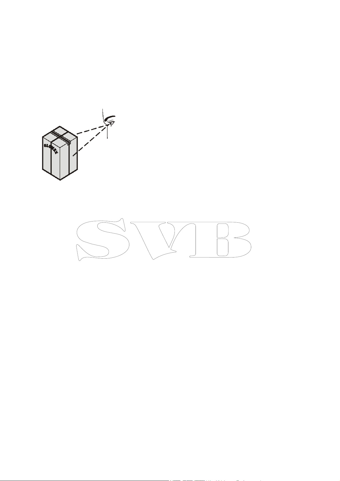
3.VERSANDINFORMATIONEN
Ihre Antenne wird in einem
verschlossenen Karton, versiegelt mit dem Glomex Garan-
tiesiegelband geliefert.
Vergewissern Sie sich bei Erhalt der Antenne, daß:
- die Verpackung & das Versiegelungsband unbeschädigt
sind.
- der Lieferumfang Ihrer Bestellung entspricht
- Antenne & Zubehör unbeschädigt sind.
Sollten Beschädigungen vorliegen oder Teile fehlen informieren Sie bitte umgehend Ihren
Händler & fügen bitte, wenn
möglich, Fotos bei.
3. GENERAL DELIVERY
INFORMATION
Your Satellite Antenna is
packed in a cardboard box for
shipment sealed with a Glomex “WARRANTY SEAL” hoop
that acts as WARRANTY seal
OF THE CONTENTS.
When you receive your Satellite Antenna ensure that:
- The packaging is Undamaged and sealed with the
WARRANTY hoop.
- The delivery complies with
the order specifications.
- The antenna and accessories are undamaged.
- In case of damage or lacking
parts immediately inform, and
possibly attaching a picture,
the Distributor/Retailer.
______________________________________ ____________________________________
9
Page 10
________________________________________________________________________________
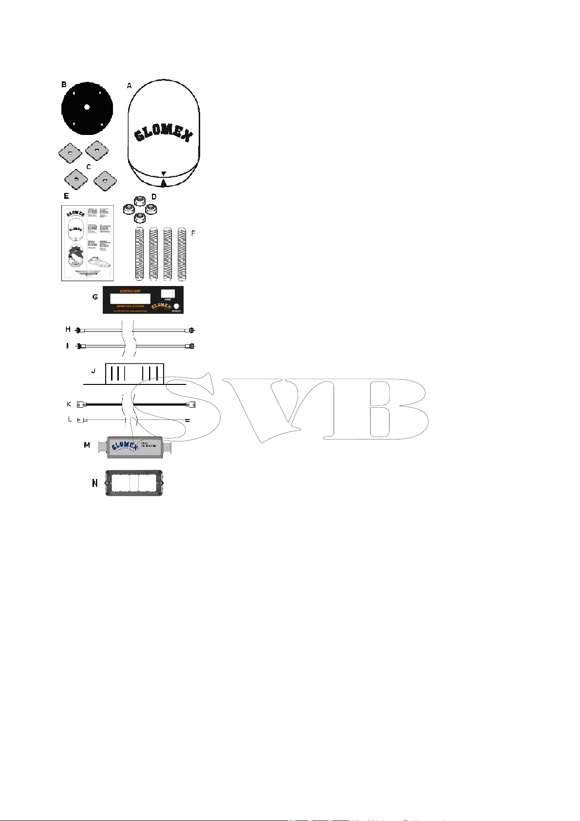
3.1 LIEFERUMFANG
(Modell V9000 Venus)
A – Antenne (1)
B – Gummidichtung (1)
C – Verstärkungen
D – selbstsichernde Muttern
M8(4)
E – Montag- & Benutzerhand-
buch (1)
F – Gewindestangen M8(4)
G – Kontrolleinheit (1)
H – Koaxialkabel 1.5 mt mit
Stecker Type “F” (2)
I - Koaxialkabel 10mt mit Ste-
cker Type “F” (1)
J - Stromversorgungsmodul
K – Stromkabel von Kontrol-
leinheit ( H ) zum Stromversorgungsmodul (K)
L – Verbindungskabel von
Stromversorgungsmodul ( K )
zum Sicherungsautomaten
M - Linearverstärker V9115
N – dunkelgraue Einbaublende
für Kontrolleinheit.
3.1 CONTENTS AND
QUANTITY
V9000 Venus)
A – Antenna (1)
B – Rubber gasket (1)
C – Reinforcements (4)
D – Self-locking nuts M8 (4)
E – User and installation
manual (1)
F – Screw cutting small bar(4)
G – Indoor control unit (1)
H – 1.5 mt coaxial cable with
male type “F” connector(2)
I – 10 mt coaxial cable with
male type “F” connector (1)
J - C.U. DC Power Supply
K – power cable Control Unit (
H ) to power supply (K)
L – connection cable power
supply ( K ) to breaker switch
M – line amplifier V9115
N – control unit flush mount
wall plate (dark grey)
(model
______________________________________ ____________________________________
10
Page 11

________________________________________________________________________________
3.2 LIEFERUMFANG
(gilt für Antenne Modell
V9100 V9103)
A – Antenne (1)
B – Gummidichtung (1)
C – Verstärkungen (4)
D – selbstsichernde Muttern
M8(4)
E – Montag- & Benutzerhand-
buch (1)
F – Gewindestangen M8(4)
G – Kontrolleinheit (1)
H – Koaxialkabel 1.5 mt mit
Stecker Type “F” (2)
I - Koaxialkabel 10mt mit Ste-
cker Type “F” (1)
I*- 10mt Koaxialkabel mit Ste-
cker Type “F” (3) nur bei V
9103
J - Stromversorgungsmodul
K – Stromkabel von Kontrol-
leinheit ( H ) zum Stromversorgungsmodul (K)
L – Verbindungskabel von
Stromversorgungsmodul ( K )
zum Sicherungsautomaten
M - Linearverstärker V9115
N – dunkelgraue Einbaublende
für Kontrolleinheit.
3.2 CONTENTS AND
QUANTITY
antenna model Saturn
V9100 V9103)
A – Antenna (1)
B – Rubber gasket (1)
C – Reinforcements (4)
D – Self-locking nuts M8 (4)
E – User and installation
manual (1)
G – Indoor control unit (1)
H – 1.5 mt coaxial cable with
male type “F” connector (2)
I - 10 mt coaxial cable with
male type “F” connector (1)
I* - 10 mt coaxial cable with
male type “F” connector (3)
only for V9103
J - Control unit DC Power Sup-
ply
K – power cable Control Unit (
H ) to power supply (K)
L – connection cable power
supply ( K ) to breaker switch
M – line amplifier V9115
N – control unit support flush
mount wall plate (dark grey)
(Valid for the
______________________________________ ____________________________________
11
Page 12

________________________________________________________________________________
3.3 LIEFERUMFANG
(gilt für Antenne
Modell Mars
V9800)
A – Antenne (1)
B – Gummidichtung (1)
C – Verstärkungen (4)
D – selbstsichernde Muttern
M8(4)
E – Montag- & Benutzerhand-
buch (1)
F – Gewindestangen M8(4)
G – Kontrolleinheit (1)
H – Koaxialkabel 1.5 mt mit
Stecker Type “F” (2)
I - Koaxialkabel 10mt mit Ste-
cker Type “F” (1)
I*- 10mt Koaxialkabel mit Ste-
cker Type “F” (3) nur bei V
9103
J - Stromversorgungsmodul
K – Stromkabel von Kontrol-
leinheit ( H ) zum Stromversorgungsmodul (K)
L – Verbindungskabel von
Stromversorgungsmodul ( K )
zum Sicherungsautomaten
M - Linearverstärker V9115
N – dunkelgraue Einbaublende
für Kontrolleinheit.
V9801
3.3 CONTENTS AND
QUANTITY
the antenna model
Mars V9801 V9800)
A – Antenna (1)
B – Rubber Packing (1)
C – Reinforcements (4)
D – Self-locking nuts M8 (4)
E – User and installation
manual (1)
G – Indoor control unit (1)
H – 1.5 mt coaxial cable with
male type “F” connector (2)
I - 10 mt coaxial cable with
male type “F” connector (1)
I* - 10 mt coaxial cable with
male type “F” connector (3)
only for V9800
J - Control unit DC Power Sup-
ply
K – power cable Control Unit (
H ) to power supply (K)
L – connection cable power
supply ( K ) to breaker switch
M – line amplifier V9115
N – control unit support flush
mount wall plate (dark grey)
(Valid for
______________________________________ ____________________________________
12
Page 13

________________________________________________________________________________
4.
INSTALLATION
DER ANTENNE
4.
INSTALLING THE
ANTENNA
4.1
MONTAGEORT
Die beste Position der Antenne
ist in der Bootsmitte, so niedrig wie möglich. Wählen Sie je
nach Ihren Bedürfnissen den
besten Montageort aus.
ACHTUNG!
Montieren Sie die Antenne
nicht nahe bei Lautsprechern
oder anderen starken Magneten. Sollte das unmöglich sein
ist der magnetische Einfluss
unter Beachtung einer unbeeinträchtigten Anzeigegenauigkeit des Steuerkompasses
zukompensieren.
4.1 LOCATIONS
Remember that the best position of the antenna is at the
centre of the boat in the lowest possible position. Choose
the most suitable position according to your needs.
ATTENTION!
Do not install the antenna
close to speakers or other
magnetic sources. Should this
not be possible, the magnetic
source must be compensated.
ACHTUNG!
Beachten Sie, daß jedes Hindernis (wie
Flaggstöcke, andere
Antennen, Radar,
Yachten, Krane, etc.)
zwischen Antenne &
Satellit das Signal behindern.
______________________________________ ____________________________________
13
IMPORTANT!
Remember that any
obstacle (such as the
flag poles, other antennas, radar, yacht
masts, cranes etc.)
between the antenna
and the satellite, will
obscure the signal.
Page 14

________________________________________________________________________________
4.2
VORBEREITUNG DER
AANTENNE
Die 4 verzinkten Schrauben in
der Antennegrundplatte sind
nacheinander durch die Gewindestangen (G) unter Verwendung von Loctite 638 zu
ersetzen.
4.2 HOW TO PREPARE
THE ANTENNA
Under the base of the Radome
the M8 galvanized bolts must
be replaced one at the time
with the threaded bars (G) using a retaining glue (such as
Loctite 638).
4.3 ANSCHLUSS DES
KOAXKABELS IN DER
ANTENNE
Die Antennenabdeckung
braucht zum Anschließen des
Koaxkabels nicht geöffnet zu
werden.
Mars V9801 V9800
An der Grundplatte der Antenne ist eine kleine, mit 4 Blechtreibschrauben verschlossene
Klappe, die Zugang zur „F“
Buchse, an die das Koaxkabel
angesteckt wird, bietet .
Fädeln Sie das Koaxkabel vor
dem Anschließen durch das
Loch in der Klappe, stecken
Sie den „F“-Stecker sicher fest
& schließen Sie die Klappe mit
den 4 Blechtreibschrauben.
4.3 WHERE CONNECT
THE COAXIAL CABLE
IN THE ANTENNA
for all the antenna model)
To connect the coaxial cable
(I) to antenna, the dome doesn’t need to opened.
Mars V9801 V9800
At the base of the dome there
is a small door, closed with 4
self-tapping screws, that allows to reach the female type
“F” socket, to which the coaxial cable(I) must be connected.
Before connecting the coaxial
cable, slip it inside the hole of
the door, and after tightly fixing the male type “F” connector, close the door with the 4
self-tapping screw.
(Valid
ACHTUNG!
Entfernen Sie vor der Montage
der Antenne die M4 Schraube
unter der Antennengrundplatte. Tun Sie dies vor Montage
der Antenne auf dem Heckbügel oder einer anderen Halterung.
______________________________________ ____________________________________
14
ATTENTION!
Before installing the antenna
remove the M4 screw under
the base of the dome .
This operation must be done
before fixing the antenna
dome to the roll bar or other
support.
Page 15

________________________________________________________________________________
4.4 MONTAGE DER ANTENNE
Platzieren Sie die Gummidichtung so, daß die beiden Löcher
genau parallel zur Querachse
& mittig ausgerichtet auf dem
Heckbügel sind & markieren
Sie die Position mit einem Filzstift.
Entfernen Sie die Gummidichtung & bohren Sie 4 Löcher
mit einem 8,5mm Bohrer.
Verbinden Sie die jeweils diagonal gegenüberliegenden Löcher mit einer Linie & bohren
Sie am Schnittpunkt ein 28mm
Loch.
4.4 HOW TO MOUNT
THE ANTENNA
Place the RUBBER GASKET
(B) so that the 2 holes are
perfectly parallel to the transverse axis and centrally
aligned as to the roll bar,
marking in the positions with
a felt-tip pen.
Remove the RUBBER GASKET
(B) and bore four holes using
a drill with a 8,5 mm Ø iron
bit.
Trace the diagonal lines over
the holes and at the point of
intersection bore another hole
using a drill with a 28 mm Ø
disk cutter.
Entfernen Sie die äußeren
Schrauben der Antennenabdeckung mit einem Kreuzschlitzschraubenzieher & entfernen
Sie die beiden Blockierungen
(Kabelbinder). Heben Sie die
Schrauben gut auf.
Richten sie die Gummidichtung
genau mit den Löchern aus.
Using a cross-tipped screwdriver, unscrew the external
screws of the RADOME and
open the dome and remove
the blocks ( 2 collars tie).
KEEP THE SCREWS IN A SAFE
PLACE.
Position the RUBBER GASKET
(B) so that the holes are
aligned.
______________________________________ ____________________________________
15
Page 16

________________________________________________________________________________
Richten Sie die “Vorne” Markierung sorgfältig bugwärts
aus.
Platzieren Sie die Antennengrundplatte so, dass die Stehbolzen durch die Löcher in der
Halterung stehen.
Mit der kurzen Seite nach unten sind die Verstärkungen
„C“ auf die Stehbolzen zu fädeln.
Carefully position the tracking
symbol stem wards.
Insert the base of the ANTENNA (A) into the four
holes.
Ensuring that the short sections are turned downwards,
position the REINFORCEMENTS (C) against the studsbolts.
Schrauben Sie die selbstsichernden Muttern auf die
Stehbolzen
Ziehen Sie die Muttern fest
Screw in the M8 SELFLOCKING
NUTS (E).
Tighten firmly
______________________________________ ____________________________________
16
Page 17

________________________________________________________________________________
4.5 Koaxialverkabelung
der SAT-Antenne
entfernen Sie wie auf der Abbildung die Isolierung des
Koax-Kabels & falten Sie das
Abschirmgitter nach hinten
Schrauben sie den Stecker auf
das Kabel.
Schieben Sie das Koax-Kabel
durch das dazu bestimmte
Loch in der Antennengrundplatte. Schließen Sie erst den
Innenleiter dann den drehbaren Metallring des “F” Steckers
an.
4.5 MOUNTING THE
TYPE “F” MALE CONNECTOR ON THE
COAXIAL CABLE
Strip the SAT CABLE (G) and
reverse back the mesh as
shown by the drawing.
Screw the CONNECTORS (H)
to the SAT CABLE (G).
Put the coaxial cable in the
hole used for the passage of
the cable in the relevant support inside the base of the
dome. Connect it, inserting the
inner conductor first and then
rotating the metal ring of the
type “F” connector.
5. Montage des Kontrollmoduls
Das aus der Antenne herausführende Koax-Kabel ist an der
mit ANTENNA bezeichneten
“F”-Buchse an der Hinterseite
des Kontrollmoduls anzuschließen.
ACHTUNG: vertauschen Sie
das Antennen- nicht mit dem
Empfängerkabel! Dadurch
könnte der Empfänger ernsthaft beschädigt werden.
In diesem Fall leistet Glomex
keinen Ersatz für die Beschädigung des Empfängers.
5. installing the indoor controlunit (all models)
The indoor control unit installation is quite easy: the coaxial
cable coming out from the antenna unit must be connected
to the type “F” female socket
labelled ANTENNA on the back
of the control unit.
ATTENTION: do not reverse
the antenna cable with the receiver cable or you could seriously damage it.
Glomex does not respond of
the damages caused to the receiver/decoder
______________________________________ ____________________________________
17
Page 18

________________________________________________________________________________
5.1 ANSCHLUSS DER
INTERNEN KONTROLLEINHEIT (V9000,
V9100, V9801)
Verwenden Sie zum Anschluss
eines digitalen Sat-Empfängers
oder –decoders das mitgelieferte 1,5m lange Koaxkabel.
Schliessen Sie dieses an der
mit RECEIVER bezeichneten
„F“-Buchse der Kontrolleinheit
& an der LNB IN bezeichneten
„F“ Buchse des digitalen SatEmpfängers an.
Sollten Sie eine größere Kabellänge als 10m benötigen so
können Sie ein neues Kabel
durch Montage von 2 „F“ Steckern an die nötige Länge
hochqualitativen Satelliten-Koaxkabels anfertigen.
5.2 ANSCHLUSS DES
EMPFÄNGERS
Digitaler SAT-Empfänger & TVGerät sind je nach vorhandenen Buchsen anzuschließen.
Sollte der SAT-Empfänger wenig Empfindlichkeit aufweisen
wird die Installation eines Verstärkers V9115 empfohlen.
Ziehen Sie die Handbücher
von TV-Gerät & SAT-Empfänger hinzu.
5.1 CONNECTING THE
CONTROL UNIT
(V9000, V9100, V9801)
To connect a Digital sat receiver or satellite decoder, use the
supplied 1.5 meters coaxial
cable, and connect it to the
type “F” female socket labelled
RECEIVER on the control unit
and at the type “F” female
socket labelled LNB IN on the
digital satellite receiver.
If a coaxial cable long more
than 10 meters is required,
wire a new cable of the required length with an high
quality satellite coaxial cable
and 2 suitable type “F” connectors.
5.2 CONNECTING THE
RECEIVER
The connection of the digital
satellite receiver and the TV,
must be carried out according
to the available sockets.
In case the satellite receiver is
characterized of weak sensibility is suggested to install the
supplied line amplifier V9115.
In order to decide which is the
most suitable solution, read
the TV and the sat receiver’s
user manuals.
5.3 MONTAGE DER
KONTROLLEINHEIT
Die Kontrolleinheit kann mit
der mitgelieferten Wandhalterung an eine vertikale Wand
montiert werden.
Mit den mitgelieferten Montageschienen ist eine horizontale
Über- oder Unterdeckenmontage möglich.
______________________________________ ____________________________________
18
5.3 MOUNTING THE
CONTROL UNIT
The control unit can be fixed
to a vertical wall through a
wall plate from Vimar is included in the antenna box
Through the brackets included
in the box’s antenna it’s possible to fix the control unit on
a horizontal plan or on a ceiling as illustrated on the picture.
Page 19

________________________________________________________________________________
5.4 ANSCHLUSS DER
STROMVERSORGUNG
(alle Modelle)
Die Kontrolleinheit wird an
eine Gleichstromquelle von 10
bis 30V angeschlossen.
Ein zweipoliges Stromversorgungskabel (Rot & Schwarz)
1,5m lang, wird mitgeliefert.
Der rote Draht ist an den
PLUS-, der schwarze Draht an
den MINUS-Pol der Stromquelle anzuschließen.
Der Anschluss an einen 5A Sicherungsautomaten/Schalter
am Bordpaneel wird empfohlen, um die Stromversorgung
der Antenne in Perioden der
Nichtverwendung abschalten
zu können.
Die Stromversorgung muss
einen Mindestquerschnitt von
4mm² haben. Längere Versorgungskabel als 10m müssen
einen Mindestquerschnnitt von
6mm² haben.
ACHTUNG!
Zur Vermeidung von korrosionsauslösenden galvanischen
Strömen & für elektronische
Komponenten schädlichen statischen Entladungen muss das
Boot ein wirksames Erdungssystem, an das alle Elektrogeräte & elektronische Komponenten anzuschließen sind,
besitzen.
5.4 WHERE AND HOW
CONNECT THE POWER
SUPPLY (Valid for all
the antenna models)
The indoor control unit can be
fed with a direct current from
10V to 30V.
The control unit, fed with direct current, is supplied with bipolar red and black cable 1.5
metres long.
The red wire must be connected to the positive pole and
the black cable to the negative
pole of the boat battery.
It’s a good rule to use a circuit
breaker 5 A switch installed on
the boat instrumentation panel
in order to remove the feeding
to the equipment during the
long inoperative periods.
The feeding line coming from
the batteries must be composed of 2 wires, 1 RED and 1
BLACK, with a minimum section of 4 square millimetres. If
it is required a cable longer
than 10 meters, the section
becomes 6 square millimetres
minimum.
IMPORTANT!
In order to prevent current
leakage or electrostatic
charges from damaging the
electronic components of the
antenna, ensure that the boat
has an efficient earthing system, and that all the electronic
appliances and equipment are
connected to it.
______________________________________ ____________________________________
19
Page 20

________________________________________________________________________________
5.5 ANSCHLUSS DER KONTROLLEINHEIT(V9103,V9800)
Verwenden Sie zum Anschluss eines digitalen SatEmpfängers oder –decoders das mitgelieferte
1,5m lange Koaxkabel. Schliessen Sie dieses an
der mit RECEIVER bezeichneten „F“-Buchse der
Kontrolleinheit & an der LNB IN bezeichneten „F“
Buchse des digitalen Sat-Empfängers an.
Sollten Sie eine größere Kabellänge als 10m benötigen so können Sie ein neues Kabel durch Montage von 2 „F“ Steckern an die nötige Länge hochqualitativen Satelliten-Koaxkabels anfertigen.
Digitaler SAT-Empfänger & TV-Gerät sind je nach
vorhandenen Buchsen anzuschließen. Sollte der
SAT-Empfänger wenig Empfindlichkeit aufweisen
wird die Installation eines Verstärkers V9115 empfohlen.
Ziehen Sie die Handbücher von TV-Gerät & SATEmpfänger hinzu.
5.5 WHERE CONNECT THE CONTROL
UNIT(V9103,V9800)
To connect a Digital sat receiver or satellite decoder, use the supplied 1.5 metres coaxial cable,
and connect it to the type “F” female socket labelled RECEIVER on the control unit and at the
type “F” female socket labelled LNB IN only one of
the digital satellite receiver.
If a coaxial cable long more than 10 metres is required, wire a new cable of the required length
with a high quality satellite coaxial cable and 2
suitable type “F” connectors.
The connection of the digital satellite receiver and
the TV, must be carried out according to the available sockets.
In case the satellite receiver is characterized of
weak sensibility is suggested to install the supplied line amplifier V9115 (1 pc.)
In order to decide which is the most suitable solution, read the TV and the sat receiver’s user
manuals.
______________________________________ ____________________________________
20
Page 21
________________________________________________________________________________
Dieses Handbuch führt Sie einfach & intuitiv in den Gebrauch
der Glomex Satellitenantenne
ein.
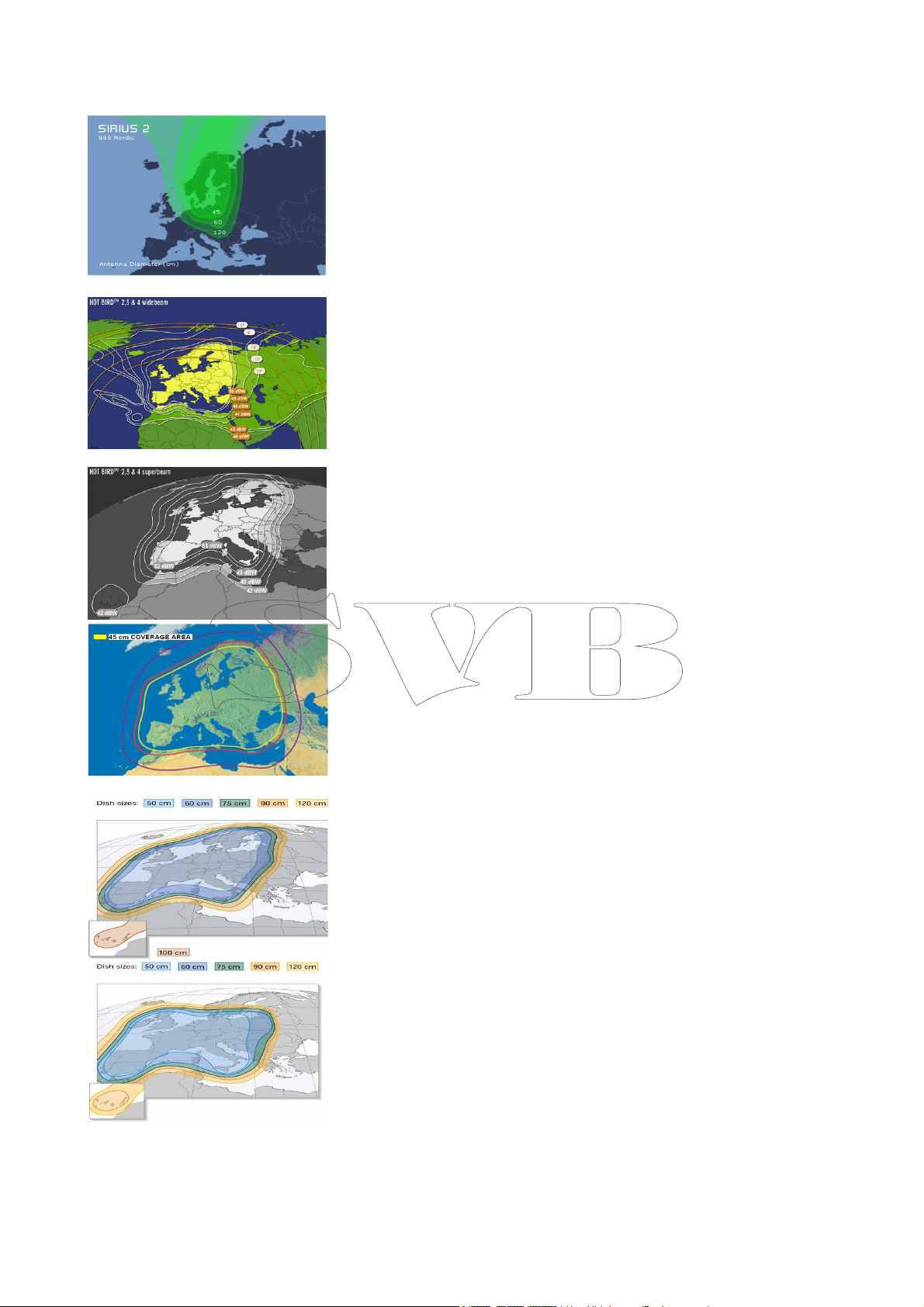
Satelliten TV gehört zu den
wenigen Medien, die weltweit
Informationen zur Verfügung
stellen, Solange man sich im
Abdeckungsbereich des gewünschten Satelliten befindet.
Der Abdeckungsbereich des
Satellitensignals ist auf den
Abbildungen zu sehen,
Die Hauptursachen schlechten
Empfangs von Satelliten-TVAntennen sind Hindernisse am
Boden. die zwischen Satellitenantenne & Satellit stehen
können wie z.B. Segelbootmasten, Krane, Antennen,
Flaggen, etc. auf derselben
Höhe wie die Satelliten-TV-Antenne.
Weiters wird das Satellitensignal sehr durch Wetterbedingungen wie Gewitterwolken &
-systeme, Eiswolken, etc beeinflusst.
6.USER MANUAL
This manual is intended to be
an useful instrument to learn
in an easy and intuitive way
how to use the GLOMEX satellite antennas.
Sat TV is one of the few media, which allows the reception
of information from anywhere
in the world, as long as inside
the coverage area of the satellite the user wishes to receive.
The signal transmitted by the
satellite generally has a wide
coverage area as illustrated in
the indicative picture and
therefore, guarantees the vision of the same TV programs
in various areas.
That is anyway important to
remember that the ground
obstacles are the main causes
of sat antennas malfunction.
The ground obstacles are all
those bodies which can be located between the satellite and
the parabolic dish, such as the
masts of sailing boats moored
close to the user’s boat,
cranes, radar antennas located
on the same level of the sat
antenna, flags, VHF antennas
etc.
The signal transmitted by the
satellite is also affected by the
weather conditions (stormy
cloud systems or icy clouds)
6. BENUTZERHANDBUCH
______________________________________ ____________________________________
21
Page 22

________________________________________________________________________________
6.1
EINSCHALTEN
A – Ein/Aus Schalter
B – Zweizeiliges alphanumeri-
sches Displaye.
b1 – 1. Zeile: gewünschter
Satellit
b2 –gerade laufende Funktion
C – Satellitenauswahl- & Ener-
giespartaste
Schalten Sie den Ein/AusSchalter auf 1. Die Antenne
beginnt automatisch mit der
Suche nach dem gewählten
Satelliten. Dies dauert zwischen 20 Sekunden & 2 Minuten, je nachdem wie stark sich
das Boot bewegt. (bei sehr
starken Bootsbewegungen
kommt möglicherweise kein
Empfang zustande.
6.2
AUS
WAHL DER
SPRACHE
Beim Einschalten der Kontrolleinheit können Sie, wenn
“Glomex” auf dem Display erscheint mit Druck auf den
Knopf C zwischen Italienisch,
Englisch, & Französisch wählen. Beim Ausschalten des Gerätes mit dem Schalter A wird
die Einstellung gespeichert.
6.1 SWITCHING ON
A – Power switch
B – Alphanumeric display
composed by two line.
b1 - first line: used for
the satellite signal that we
want to receive.
b2 - second line: function
running
C – key for satellite selection
and to turn on and off the energy saving system.
In order to switch the control
unit on, act on the power
switch (A), positioning it on 1.
The antenna begins automatically searching for the selected satellite, taking from a
minimum of 20 seconds up to
a maximum of 2 minutes, depending on the movement of
the boat (in condition of big
movements it is possible that
the antenna does not receive
the signal for the wrong calibration of the system).
6.2
LANGUAGE SELEC-
TION
At the start up of the control
unit, when you read “Glomex”
on the display, you can chose
pushing the button (C) the
languages between Italian,
English, Spanish, French. To
save the setting just turn off
and on the unit with the
switch (A)
______________________________________ ____________________________________
22
Page 23

________________________________________________________________________________
6.3 AUSWAHL DES SATELLITEN
Drücken Sie solange wiederholt auf die Taste für
die Satellitenauswahl (C) bis in der ersten Zeile
des Displays der gewünschte Satellit erscheint.
N.B. folgende Satelliten können ausgewählt werden:
ASTRA2-N
Wählen Sie diese Position, wenn Sie sich im Nordteil der Abdeckung des Satelliten ASTRA 28°E befinden
ASTRA2-S
Wählen Sie diese Position, wenn Sie sich im Südteil der Abdeckung des Satelliten ASTRA 28°E befinden
ASTRA1-N
Wählen Sie diese Position um den Satelliten
ASTRA 19°E zu empfangen.
HOTBIRD
Wählen Sie diese Position um den Satelliten HOTBIRD 13°E zu empfangen.
SIRIUS
Wählen Sie diese Position um den Satelliten SIRIUS 5°E zu empfangen.
6.3 CHOOSE THE SATELLITE TO
SEARCH
Push several times the key for satellite selection
(C) as long as the display (b1) corresponding to
the desired satellite turns on.
N.B. The following satellites are available from our
system
ASTRA2-N
Choose this position when located on the NORTH
part of the footprint of ASTRA 28°E satellite.
ASTRA2-S
Choose this position when located on the SOUTH
part of the footprint of ASTRA 28°E satellite.
ASTRA1-N
Choose this position to receive the signal of ASTRA 19°E satellite.
HOTBIRD
Choose this position to receive the signal of HOTBIRD 13°E satellite.
SIRIUS
Choose this position to receive the signal of SIRIUS 5°E satellite.
ATLANTIC BIRD
Wählen Sie diese Position um den Satelliten ATLANTIC BIRD 5°W zu empfangen.
HISPASAT
Wählen Sie diese Position um den Satelliten HISPASAT 30°W zu empfangen.
Nach Auswahl des gewünschten Sateliten beginnt
die Antenne sofort nach dessen Sdignal zu suchen
& zeigt in der ersten Zeil des Displays den Namen
des Satelliten an.
ATLANTIC BIRD
Choose this position to receive the signal of ATLANTIC BIRD 5°W satellite
HISPASAT
Choose this position to receive the signal of HISPASAT 30°W satellite.
After choosing the desired satellite, the antenna
begins immediately the search for signal showing
on the display (b1) the name of the satellite
______________________________________ ____________________________________
23
Page 24

________________________________________________________________________________
6.4 INFORMATION ÜBER
POSITIONEN VON RADIO- & TVSATELLITEN
Die Satelliten liegen in einer Erdumlaufbahn über
dem Äquator in ca. 36.000 Km Höhe. Alle Satelliten befinden sich an fixen Positionen weshalb sie
auch “geostationär” genannt werden. Da der
Strombedarf der Satelliten mit Solarpaneelen gedeckt wird ist deren Sendeleistung zur Erde relativ
gering & auf eine geringe Fläche konzentriert. Die
Sendeleistung ist in der Mitte des abgedeckten
Gebietes stärker & an dessen Rand schwächer.
Die Zeichnungen verdeutlichen dies.
______________________________________ ____________________________________
6.4 INFORMATION ABOUT TV AND
RADIO SATELLITES POSITION
The satellites are positioned on an orbit in proximity of the equatorial line at the distance of 36.000
Km from the earth. All the satellites are fixed in a
well defined position of the orbit, that is why they
are called geostationary satellites. Being the satellites fed by solar panels, the power of transmission
on the terrestrial surface is low and relatively concentrated on small areas of the earth. The effect
of the satellite’s signal transmitted is condensed in
particular at the center and more weak to the end.
The footprints illustrate the area of coverage of
the satellite on the earth.
24
Page 25

________________________________________________________________________________
6.5 SUCHEN & VERFOLGEN DES SATELLITENSIGNALS
Findet die Antenne den gewählten Satelliten so
überprüft sie das Signal & zeigt, wenn dieses für
korrekt befunden wird, im Display „sat found“
(b2). Daraufhin geht die Antenne in den Verfolgungsmoduls der ebenfalls in b2 angezeigt wird
Es kann vorkommen, daß die Antenne vor dem Signal des ausgewählten das eines anderen Satelliten empfängt (das hängt von der Bootsposition,
der Signalstärke & den Wetterbedingungen ab). In
diesem Fall erscheint der Name des Satelliten nur
für eine Sekunde, dann sucht die Antenne weiter
nach dem ausgewählten Satelliten & speichert die
Position des eben gefundenen.
Die Kontrolleinheit speichert die Position des letzten ausgewählten Satelliten & beginnt nach dem
Einschalten nach diesem letzten zu suchen. Während die Antenne sucht können über SAT-Empfänger & TV Gerät TV-Programme gesehen & Radio
gehört werden.
6.5. SATELLITE SIGNAL SEARCH AND
TRACKING
When the antenna finds the selected satellite, the
signal is checked and if it is correct, on the display
appears ‘sat found’ (b2). Successively goes in to
the tracking function, which is indicated in b2.
Sometimes it may happen that the antenna captures another satellite earlier than the selected
one (it depends on the position where the boat is
located, the strength of the transmitted signal and
on the weather conditions). In this case the display writes the satellite name just for a second,
then the antenna starts searching the selected
satellite, considering the position of the satellite
just found.
The control unit stores the last satellite position
selected on it, and when switched on the following time, it starts searching for this last satellite
position. When the antenna is on tracking, TV
programs can be watched and radio stations can
be heard, through a sat receiver and a TV.
6.6 ENERGIESPARFUNKTION
Liegt das Boot fest vertäut & bewegt sich wenig
so kann die Energiesparfunktion aktiviert werden.
Das minimiert nicht nur Energieverbrauch sondern
auch Lärm der Antenne.
Einschalten der Energiesparfunktion:
Drücken Sie den Satelliten-Auswahl-Knopf “C” &
Sie sehen ob die Funktion ein- (enabled) oder aus
geschaltet (disabled) ist. Mit einem weiteren
Druck dieser Taste können Sie zwischen beiden
Zuständen hin- & herschalten, woraufhin im Display der neue Modus angezeigt wird.
Bewegt sich bei eingeschalteter Energiesparfunktion das Boot zwei Minuten lang nicht, so bleibt die
Antenne in der Position, in der sie das stärkste Signal empfangen hat, stehen.. Bei Abnahme der
Signalstärke oder einer Bootsbewegung größer als
6° in 2 Minuten reaktiviert sich die Antenne &
stellt sich auf die maximale Signalstärke ein.
6.6 ENERGY SAVING FUNCTION
(SLEEP MODE)
When the boat is moored and the displacements
are limited, the energy saving function can be activated. This function, besides minimizing the
power consumption, avoids the noise coming from
the antenna. In order to enable this function,
push one time the button for satellite selection (C)
and you can see if it is enabled or disabled. Pushing one more time you can change the status,
then the new status selected is shown on the display.
When the function is enabled, if the boat has not
displaced within two minutes, the antenna stops
in the position of the maximum signal received by
the satellite. A decrease of received signal level or
boat movement of 6° in two minutes, wakes the
antenna up and recovers the maximum level of
signal which can be received.
______________________________________ ____________________________________
25
Page 26

________________________________________________________________________________
7. FUNKTION DER KONTROLLEINHEIT
Einschalten – das Display zeigt:
** GLOMEX ** DVB ‘‘ SAT TV ANTENNA ‘
ANTENNA INIT – die Antenne macht sich zur
nächsten Funktion bereit
CALIBRATION – Kalibrierung des Kreisels
SOUTH SEARCH– die Antenne richtet sich nach
Süden aus
SATELLITE SEARCH – wenn vom Benutzer kein
anderer Satellit ausgewählt wird sucht die Antenne den zuletzt empfangenen.
SATELLITE FOUND – wird nach Finden eines
Satelliten & vor der NIT Überprüfung angezeigt.
Wenn der NIT stimmt wird „Satellite found“ angezeigt.
SIGNAL LOST – die Antenne hat das Signal verloren.
ANT. STANDBY – wird angezeigt wenn die Antenne das Signal empfängt & das Boot sich eine
bestimmte Zeit lang nicht bewegt. Die Antenne
bleibt in der Stellung des stärksten Signals stehen
& aktiviert die Energiespar- & Lärmreduktionsfunktion.
SEARCH NEXT SAT. – die Antennen wechselt
von einem zum nächsten Satelliten
7. CONTROL UNIT FUNCTION
Start up –the display shows‘
** GLOMEX ** DVB ‘‘ SAT TV ANTENNA ‘
ANTENNA INIT- on this step the antenna goes
in the position for the next function
CALIBRATION – step of gyroscope calibration
SOUTH SEARCH – rotation of azimuth until the
antenna finds the south
SATELLITE SEARCH – if the user does not select a different satellite the antenna starts searching the last satellite received
SATELLITE FOUND – displayed when the satellite signal is found before the NIT check. If the
the NIT is correct, the message “Satellite Found”
is displayed.
SIGNAL LOST – satellite signal lost
ANT. STANDBY – displayed if the antenna re-
ceives the signal and the boat remains in stand-by
for a certain period. In that case the antenna
stops at the maximum signal, reduces the noise of
its functioning and activates the energy saving
function
SEARCH NEXT SAT. – this message is displayed
when the antenna goes from one satellite signal
to another
NIT CHECKING – unmittelbar nach finden &
beim darauffolgenden Prüfen des Satelliten
At. ERR.1 – das Kabel von Kontrolleinheit zur Antenne ist unterbrochen!
______________________________________ ____________________________________
NIT CHECKING – displayed after the satellite
found to check if the signal is the right one
Att. ERR.1 – connection cable control unit – antenna disconnected!
26
Page 27

________________________________________________________________________________
8. Tilt Kalibrierung
Das Satellitensignal kann auf 2 unterschiedliche
Arten polarisiert gesendet werden:
linear polarisiert (Europa)
Zirkular polarisiert (USA)
Ihre Antenne arbeitet mit beiden Polarisierungsarten, es muss aber der richtige LNB für den Empfang des gewünschten Satelliten montiert sein
Zirkular- polarisierte Satellitensignale benötigen
zur Empfangsoptimierung keine Einstellung des
Tilt
Linear-polarisierte Signale benötigen bei der Installation eine genaue Einstellung der Polarisation
zur optimalen Ausrichtung des LNB auf das Satellitensignal
8. SKEW CALIBRATION
Satellites may transmit their signals in one of two
different polarization modes (linear polarization
for
Europe, circular for USA).
Your antenna is designed to operate with linear or
circular polarized satellite transmissions,
but you must have the appropriate LNB installed
for the satellite that you want to
receive.
Circular polarized satellite transmissions do not require polarization adjustment to
optimize the reception. Linear polarized satellite
transmissions require at the installation
adjustment of _ polarization_ to optimize the
alignment of the LNB to the angle of the
signal from the satellite.
Wenn sich die Antenne auf derselben geographischen Länge befindet wie der Satellit so werden
seine horizontalen & vertikalen Signale genau horizontal bzw. vertikal empfangen. Wenn der Satellit östlich oder westlich der Antenne steht scheinen die Polarisationsebenen des Signale um dieselben Winkel im oder gegen den Uhrzeigersinn
aus der Horizontale bzw. Vertikale verdreht. Die
Größe des Winkels hängt davon ab wieweit östlich
oder westlich der Antenne der Satellit steht oder
wieweit die Antenne vom Äquator entfernt ist.
______________________________________ ____________________________________
When you are on the same longitude as the satellite, its_ horizontal and vertical signals
will be purely aligned to your horizon. When the
satellite is east or west of your
longitude, the satellite signals will appear to be
rotated clockwise or counterclockwise
from pure horizontal and vertical. Both horizontal
and vertical signals from a satellite
will appear to be rotated the same amount and
are always perpendicular to each other.
The amount of rotation is dependent on how far
east or west the satellite is from you
and how close you are to the Equator.
27
Page 28

________________________________________________________________________________
Der LNB-Tilt sollte, wenn das Boot im selben Gebiet bleibt & seine geographische Länge weniger
als +/- 10° ändert, keiner Neueinstellung bedürfen. Bei Längenänderungen von wesentlich mehr
als +/- 10° sollte die LNB Stellung für einen optimierten Empfang neu eingestellt werden.
Vom Werk ist die Antenne ist auf eine geogr. Länge von 12° Ost zum Empfang eines Satelliten auf
13° Ost eingestellt.
Lösen Sie zur Neueinstellung des LNB seine 4
Montageschrauben (siehe Bild). Stellen Sie auf Ihrem SAT-Empfänger die Funktion SQ – „Signalqualität“ ein. Nun können Sie während des Verstellens des LNB die Veränderungen der Signalstärke beobachten. Fixieren Sie den LNB in der
Position die Ihnen das stärkste Signal liefert
It should NOT need to be re adjusted if the boat
stays in the same location and is operating on the
same, otherwise if you move in a place far more
than 10° of longitude you should re adjust the
LNB positions to have the max signal on the receiver.
The default antenna is set in a zone of longitude
12° Est receiving the satellite in 13°Est .
To set the LNB you had to screw off the four
screw used to fix it to the Antenna (look the picture). With your receiver (look to the receiver
manual) open the function to see the S.Q. (signal
quality). Now you can move the LNB looking the
signal quality from your receiver in order to screw
the LNB in the position where you have a better
S.Q.
______________________________________ ____________________________________
28
Page 29

________________________________________________________________________________
______________________________________ ____________________________________
29
Page 30

________________________________________________________________________________
TAB1. Tabella riassuntiva modelli
Produktdaten & -charakteristika können ohne Vorankündigung geändert
werden April 2008
______________________________________ ____________________________________
TAB1. Table of satellite antenna
Specifications may change without prior notice
April 2008
30
Page 31

________________________________________________________________________________
Spezifikationen
V9000 V91 00 V910 3 V98 01 V 9800
Reflek tor durc hme sser
Rad om Ab messung en
Antenn en ge wicht 10k g 12,5kg 13k g 15k g 1 5,5 kg
Verfolg un gsra te 50° /sec 50 °/se c 50°/s ec 5 0°/sec 50°/s ec
Verstä rku ng 3 2dB @ 1 2GHz 3 4d B @ 1 2 GHz 34dB @ 1 2 GHz 35,5@ 1 2 GHz 35,5@ 1 2 GHz
Reflek tor ty p Prim e foc us
Polarisa tion Linear (v & h) Lin ear (v & h) Linea r (v & h) Linear (v & h) Linea r (v & h)
LNB Fre que nzbereich
Rad om Abd eck un g
Str om versor gu ng 12 – 2 4V DC
Betri ebste mp era tur
Dreh bere ich Azimu th
Bereich Eleva tio n 15 ° - 9 0° 5° - 90 ° 5 ° -90 ° 1 5° - 9 0° 15 ° - 90 °
St abilisieru ng
durc h
Sa tellite nidenti fikation
Min EIRP 5 0Db w 49D bw 4 7D bw 49D bw 47Db w
Bereit für Up gra des
Deco dera usg äng e 1 1 3 1 3
39c m 47c m 47c m 60c m 60c m
42 x 50 50 x 62 50 x 6 2 66 x 66 6 6 x 66
Pri me foc us
Splas h-plat e fee d
10,7 – 1 2,7 5 GHz 1 0,7 – 1 2,75 GHz 1 0,7 – 12,75 GHz 1 0,7 – 1 2,7 5 GHz 10, 7 – 12, 75 GHz
UV bestä ndi g UV bestä ndi g UV b estä ndi g UV best än dig UV bestä ndi g
2A
0° - 70 °C 0° - 7 0°C 0° - 70 °C 0° - 7 0°C 0 ° - 70 °C
un be grenz t un be grenzt u nbegr enz t unb egr enzt unb eg renz t
2-Achs en Kreisel 2-Ac hsen Kreisel 2-Achsen Kreisel 2-Achse n Kreisel 2-Achse n Kreisel
NIT NIT NIT NIT NIT
Ja Ja Ja Ja Ja
Spl ash-plat e fee d
12 – 2 4V DC
2,5A
Prim e foc us
Spl ash-plat e fee d
12 – 2 4V DC
2,5A
Pri me foc us
Spl ash-pla te fee d
12 – 24V DC
3A
Pri me foc us
Spl ash-plat e fee d
12 – 24V DC
3A
DV B Digital Video Broadc asting
CRJ Coaxial Rotating Joint: Schleifringübe rt ra gu ng vo m Reflekt or – kein sich aufwickelnd es Kabel
EGS Elec tro nic Gyroscope Stabilized: die direk t am Refle kt or installiert en Dreh beschleu nig un gsse nso-
ren e rlaub en den blitzartigen Ausgleic h de r Stampf- & Roll bewe gu ng en des Boot es
SCC Sin gle Ca ble Conne cti on : n ur ein Kabel zwischen An tenne & TV-Gerät
No Co mp ass
Daher kein e Kom pensation od er D eviat ion oder Störungen durch m ag ne tische Metallobjekte an
Bord
No GPS
NIT Net wo rk Informa tio n Table: ein spezielles Über pr üf un gssystem das sicherstell t, dass die An te nne
de m gewü nsc ht en Satellit en folgt, da durch die kleinen Trennu ngswin kel z wisc hen d en Satelliten
leich t Fehler en tst eh en könne n
______________________________________ ____________________________________
31
 Loading...