

Page 1

Important Notice
GlobeWave Inc. makes no representation or warranties with respect
to the contents hereof and specifically disclaims any implied
warranties of merchantability or fitness for a particular purpose.
Further, GlobeWave™ reserves the right to revise this
documentation and to make changes in the contents hereof without
obligation of GlobeWave to notify any person of such revision
changes.
Copyright ©GlobeWave Inc. 1997
All Rights Reserved
Printed in the U.S.A
GlobeWave and Com.plete PC Card are trademarks of GlobeWave Inc, Windows is a trade mark of
Microsoft Corporation, TX-CEL is a trademark of Celeritas, AT is a trademark of Hays
Microcomputer Products, EarSet is a trademark of Jabra and all other trade marks are owned by their
respective companies.
Page 2

ii
IMPORTANT NOTICE......................................................................................I
INTRODUCING THE COM.PLETE PC CARD........................................1
INTRODUCTION............................................................................................1
PRODUCT FEATURE SUMMARY:.................................................................... 1
WHAT IS IN THE PACKAGE: ...........................................................................2
TIA HEALTH/SAFETY INSTRUCTIONS.................................................3
EXPOSURE TO RADIO FREQUENCY ENERGY .................................................. 3
ANTENNA CARE AND REPLACEMENT ............................................................3
DRIVING......................................................................................................4
ELECTRONIC DEVICES..................................................................................4
CHILDREN ...................................................................................................4
BLASTING AREAS ........................................................................................ 4
POTENTIALLY EXPLOSIVE ATMOSPHERES .....................................................4
GETTING STARTED - SETTING UP THE COM.PLETE™ PC CARD.. 6
Requirements:......................................................................................... 6
INSTALLING THE COM.PLETE PC CARD HARDWARE ......................................6
Using Windows NT : ............................................................................... 6
Using Windows 95/98: .......................................................................... 10
Installing Your Com.plete PC Card Windows NT DriversError! Bookmark not
defined.
Installing Your Com.plete PC Card Windows 95/98 DriversError! Bookmark
not defined.
LOADING THE COM.PLETE PC CARD USER SOFTWARE: ............................... 17
Using Windows 95/98 and Windows NT: ............................................... 17
RUNNING AND USING DIALER ....................................................................20
ACTIVATING YOUR COM.PLETE PC CARD FOR CELLULAR SERVICE:..............23
Using and Understanding the Activation Software: ............................... 25
Programming Your PC Card For Cellular Service.................................26
USING THE DIALER .................................................................................... 28
Making a Call....................................................................................... 28
Answering an Incoming Call.................................................................28
Setting the Authentication Number ........................................................ 28
Setting the Communication Options ......................................................29
Setting the Dialer Options..................................................................... 29
Setting the Audio Options......................................................................30
THE STATUS WINDOW ...............................................................................32
TASK BAR ICONS.......................................................................................33
Mode Icon.............................................................................................33
The Signal Icon..................................................................................... 33
Page 3

iii
The Battery Icon ...................................................................................34
IMPORTANT OPERATIONAL INFORMATION ..................................35
AUTO-MODE SWITCHING CAPABILITY: ....................................................... 35
CELLULAR RECEPTION:..............................................................................36
SETTING UP WINDOWS FOR CELLULAR DATA: ............................................ 37
USING DIAL-UP NETWORKING FOR CELLULAR DATA CONNECTIONS:........... 41
Setting Up Dial-Up Networking for Cellular Data Connections: ...........41
Modem Pools: Using Cellular Error Correction & Throughput
Enhancement: ....................................................................................... 42
Setting Back “Dial-Up Networking” for Land-Based Connections: ....... 44
SENDING FAXES WITH YOUR COM.PLETE PC CARD.....................................45
Sending a Cellular Fax Using your Com.plete PC Card:.......................46
CELLULAR VOICE CALLS:........................................................................... 46
Using AT Commands To Dial................................................................ 47
APPENDIX A: PHONE COMPANY REQUIREMENTS AND NOTICES
.....................................................................................................................48
FCC RADIO FREQUENCY INTERFERENCE STATEMENT ................................. 48
FCC PART 68 RULES AND REGULATIONS ................................................... 48
FAX BRANDING COMPLIANCE.....................................................................49
INDUSTRY CANADA COMPLIANCE STATEMENT.........................................49
INDUSTRY CANADA INFORMATION: ............................................................50
APPENDIX B: AT COMMAND SUMMARY...........................................51
BASIC AT COMMANDS .................................................................................... 52
EXTENDED AT "&" COMMANDS................................................................56
AT COMMANDS FOR V42/MNP CONTROL............................................................ 59
AT COMMANDS FOR V42/MNP CONTROL............................................................ 61
RESULT CODES............................................................................................. 66
MODEM S-REGISTERS ....................................................................................68
MODEM S-REGISTERS ....................................................................................69
FAX CLASS 1 AT COMMANDS ........................................................................... 75
FAX CLASS 2 AT COMMANDS ........................................................................... 75
FAX CLASS 2.0 AT COMMANDS.........................................................................77
ROCKWELL VOICE MODE AT COMMANDS ............................................................78
IS-101 VOICE MODE AT COMMANDS ................................................................. 80
VOICE VIEW AT COMMANDS.............................................................................81
PHONEBOOK AT COMMANDS............................................................................ 82
WIRELESS (AMPS) MODE AT COMMANDS ..........................................................83
WIRELESS (AMPS) MODE AT COMMANDS ..........................................................84
WIRELESS (AMPS) MODE AT COMMANDS ..........................................................85
Page 4

iv
WIRELESS (AMPS) MODE AT COMMANDS ..........................................................86
Page 5

1
Introducing the Com.plete PC Card
Introduction
The Com.plete™ PC Card is a unique, state-of-the-art, fully integrated, single
Type III PC Card module for sending and receiving data, fax and voice
communications over the Advanced Mobile Phone System (AMPS) cellular
network as well as over conventional land-based phone network. The cellular
phone and fax/modem are optimally matched and integrated into a single PC
Card which means there is no need to connect the Com.plete PC Card to any
external device, it is a cellular phone. The result is an elimination of the
compatibility problems which usually arise with cable connected cellular phoneto-modem combinations.
Your Com.plete PC Card is enabled to perform both cellular and land-based
voice, data and fax communications using standard communication software
packages. Mode selection is fully automatic. This manual contains important
information about setting up, using, and caring for your Com.plete PC Card. It
assumes that you are familiar with the computer (hardware and software) which
will be used. Before using the product, you should read this manual carefully as it
provides important information and setup tips.
Product Feature Summary:
•
Capable
• Mobile Station Power Class III (0.6W transmit power)
• Error correction (LAP-M, MNP 2-4, MNP10, MNP10 EC ) and data
• Celeritas TX-CEL cellular throughput acceleration
system and up to 33600 Baud over landline
bis fax/modem transfer rate up to 14400 Baud
• Optional Earphone for cellular and landline voice communication
• Extended Industry Standard AT command set compatible with most common
Page 6

2
• FCC and CTIA approved
• Firmware field upgradable by user
What is in the package:
Your package should contain:
• Com.plete™ PC Card
• Antenna
• Antenna extension cable
• Land-based telephone connector with RJ-11 jack for Data Access
Arrangement (DAA)
• Phone extension cable
• Software Disks with Install and Activation Utilities
• Users Guide and Technical reference manual
• Miniature speaker/microphone - EarSet™
Page 7

3
TIA Health/Safety Instructions
IMPORTANT !!!
READ THIS INFORMATION BEFORE USING YOUR CELLULAR Com.plete PC
Card
The cellular telephone is one of the most exciting and innovative electronic products ever
developed. With it you can stay in contact with your office, your home, emergency
services, and others.
For the safe and efficient operation of your phone, observe these guidelines.
Your mobile cellular telephone is a radio transmitter and receiver. When the phone is ON,
the externally mounted antenna is the part of the phone that sends out and receives radio
frequency (RF) energy. The phone operates in the frequency range of 824 MHz to 894
MHz and employs commonly used frequency modulation (FM) techniques. When you use
your phone, the cellular system handling your call controls the power level at which your
phone transmits. The power level can range from 0.006 of a watt to 0.6 watts.
Exposure to Radio Frequency Energy
In 1991 the Institute of Electrical and Electronics Engineers (IEEE), and in 1992 the
American National Standards Institute (ANSI) updated the 1982 ANSI Standard for safety
levels with respect to human exposure to RF energy. Over 120 scientists, engineers, and
physicians from universities, government health agencies and industry, after reviewing the
available body of research , developed this updated Standard. In March 1993, the U.S.
Federal Communications Commission (FCC) proposed the adoption of this updated
Standard. To operate within this updated ANSI Standard, use your phone as described
under “Efficient Phone Operation”.
To comply with FCC RF exposure requirements, a minimum separation distance of 2 cm
(0.8 inches) must be maintained between the user/bystander and the PCMCIA cellular
modem card, including the antenna.
Antenna Care and Replacement
Do not use the phone with a damaged antenna. Replace a damaged antenna immediately.
Consult your manual to see if you may change the antenna yourself. If so, use only a
manufacturer-approved antenna. Otherwise, have your antenna repaired by a qualified
technician.
Use only the supplied or approved antenna. Non-approved antennas. modifications, or
attachments could impair call quality, damage the Card, and violate FCC regulations.
Page 8

4
Driving
Check the laws and regulations on the use of cellular telephones in the areas where you
drive. Always obey them. Also, when using your phone while driving, please:
• give full attention to driving
• use hands-free operation, if available, and
• pull off the road and park before making or answering a call if driving conditions so
require.
Electronic Devices
Most modern electronic equipment is shielded from RF energy. However, RF energy from
cellular telephones may affect inadequately shielded electronic equipment.
RF energy may affect improperly installed or inadequately shielded electronic operating and
entertainment systems in motor vehicles. Check with the manufacturer or its representative
to determine if these systems are adequately shielded from external RF energy. You should
also check with the manufacturer of any equipment that has been added to your vehicle.
Consult the manufacturer of any personal medical devices (such as pacemakers, hearing
aids, etc.) to determine if they are adequately shielded from external RF energy.
Children
Do not allow children to play with your Com.plete PC Card. It is not a toy. Children could
damage the Card, or make calls that increase your telephone bills.
Blasting Areas
To avoid interfering with blasting operations, turn OFF when in a “blasting area” or in areas
posted: “Turn off two-way radio”. Construction crews often use remote control RF devices
to set off explosives.
Potentially Explosive Atmospheres
Page 9

5
Turn your phone OFF when in any area with a potentially explosive atmosphere. It is rare,
but your phone or its accessories could generate sparks. Sparks in such areas could cause
an explosion or fire resulting in bodily injury or even death.
Areas with a potentially explosive atmosphere are often, but not always, clearly marked.
They include fueling areas such as gas stations; fuel or chemical transfer or storage facilities;
and areas where you would normally be advised to turn off your engine.
Do not transport or store flammable gas, liquid, or explosives in the compartment of your
vehicle which contains your phone or accessories.
Vehicles using liquid petroleum gas (such as propane or butane) must comply with the
National Fire Protection Standard (NFPA-58). For a copy of this standard, contact the
National Fire Protection Association, One Battery march Park, Quincy, MA 02269, Attn:
Publication Sales Division.
Page 10

6
Getting Started - Setting Up the Com.plete™ PC
Card
Your Com.plete PC Card is designed to be used with any laptop, notebook or
hand-held computer equipped with a type III PC Card slot.
Requirements:
• PCMCIA type III slot conforming to PCMCIA’s Standard Version 2.1 or
later.
• Card and Socket Services compliant to version 2.0 or later
• Windows 95/98, Windows NT, or DOS (Version 6.2 or Later)
• For data/fax communication: an application, terminal or fax software such as
HyperTerminal, ProComm Plus, WinComm, etc.(not included)
Installing the Com.plete PC Card Hardware and Drivers
Using Windows NT :
Inserting the Com.plete PC Card:
1. Make sure you have Card and Socket Services installed and configured
properly on your computer. See your computer’s documentation for more
information.
2. Hold the PC Card with the top label facing upward (see indication on the
label) and the antenna pointing away from the computer.
3. Insert the PC Card into the PC Card slot of the computer until the card seats
firmly.
Attention: Do not force the Com.plete PC Card into the slot as it may
damage the card or the device.
Installing Your Com.plete PC Card Windows NT Drivers
1. Insert the Com.plete PC Card into the computer’s type III PC Card Slot.
2. Double-click the “My Computer” icon and then the “Control Panel” icon or,
click the “Start” button on the task bar, select “Settings” from the pop-up
menu and then select “Control Panel” from the new pop-up menu.
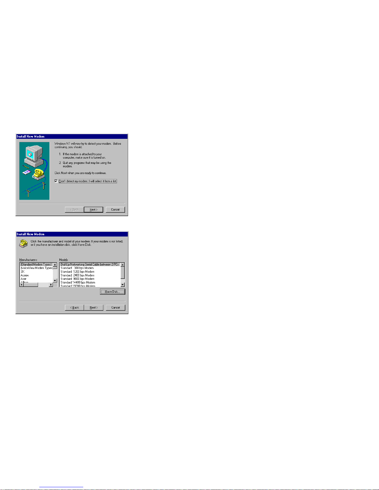
3. Double-click the “Modems” icon on the “control Panel” window. The
“Install New Modem” window is displayed
4. Check the “Don’t detect my modem; I will select it from a list” check box
and press the “Next” button.
Page 11
7
5. The selection window is displayed.
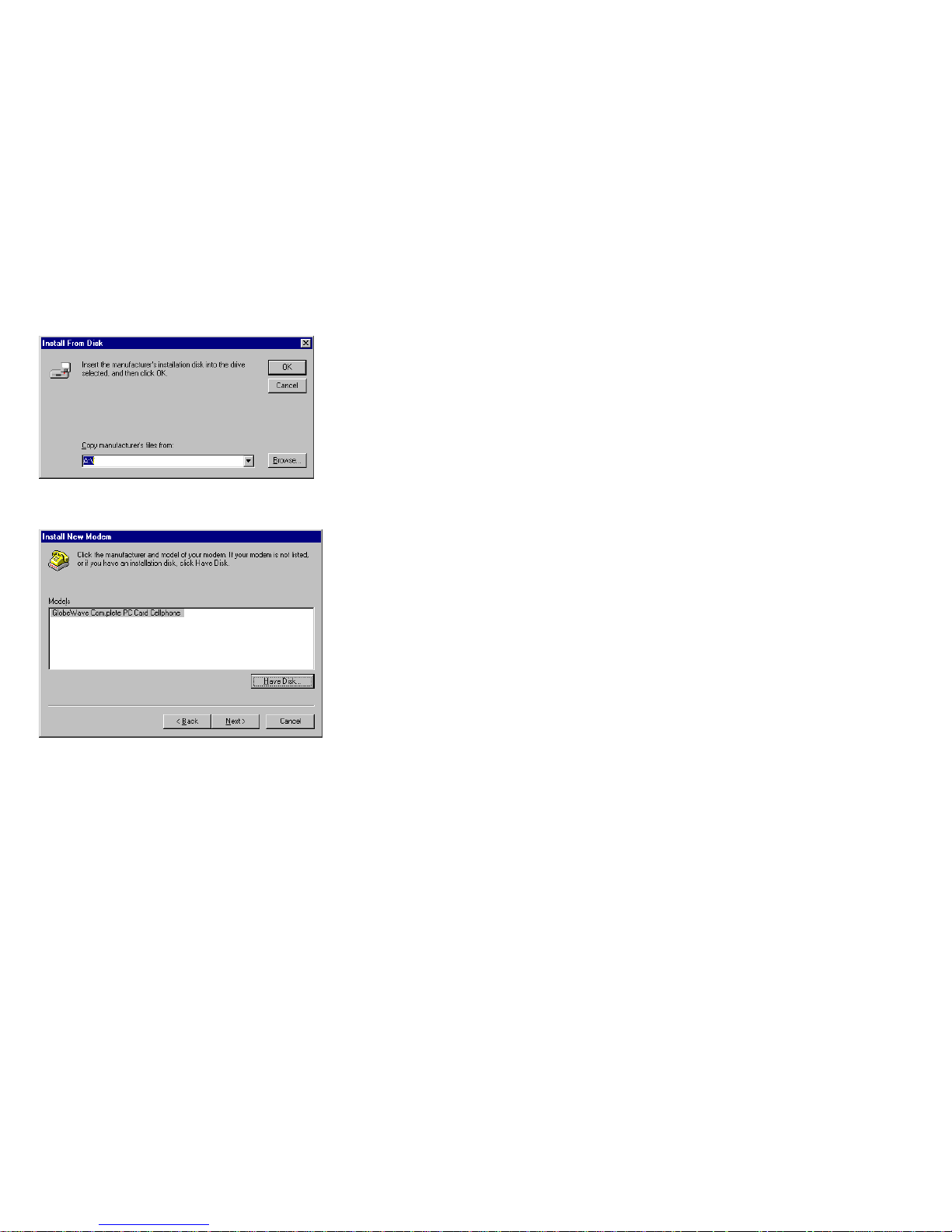
6. Press the “Have Disk…” button. In the “Install From Disk” window, verify
that A:\ is displayed in the “Copy manufacturer’s files from” box and press
the “OK” button.
Page 12
8
7. In the displayed window verify that “GlobWave Com.plete PC Card
Cellphone” is displayed in the “Models” box.
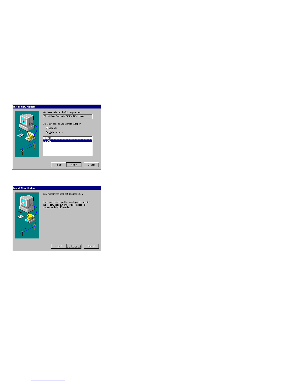
8. Press the “Next” button to install the modem. Select “COM2” in the next
window and press the “Next” button. If no COM port is shown in the
“Selected Port” box, you have to r3eboot your computer, enter the setup
menu and verify that the serial communication ports are enabled (refer to
your computer’s user guide for this action).
Page 13
9
9. The ending window is displayed. Press the “Finish” button and the syst4em
will finish the installation of your modem.
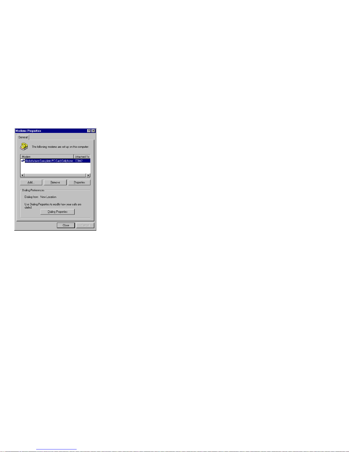
10. At the end of the installation the “Modem Properties” window will be
displayed, indicating your modem and the COM port on which it is installed.
Press the “Close” button if you do not wish to change the modem’s
configuration, or press the “Properties” button and refer to Setting up
Windows For Cellular Data: to set the configuration of your modem.
Page 14
10
Ejecting the Com.plete PC Card:
1. Make sure all software accessing the PC Card has been closed. This also
includes software that has instructed the PC Card to switch to Auto Answer
mode.
2. Press the PCMCIA eject button.
3. Remove the card when it is released.
Using Windows 95/98:
Inserting the Com.plete PC Card:
1. Facing up (see indication on the label,) insert the Com.plete PC Card to the
bottom slot – a beep or a pop up message should indicate recognition of the
card’s presence.
Attention: Do not force the Com.plete PC Card into the slot as it may
damage the card or the device.
Page 15
11
Installing the Com.plete PC Card Windows 95/98 Drivers
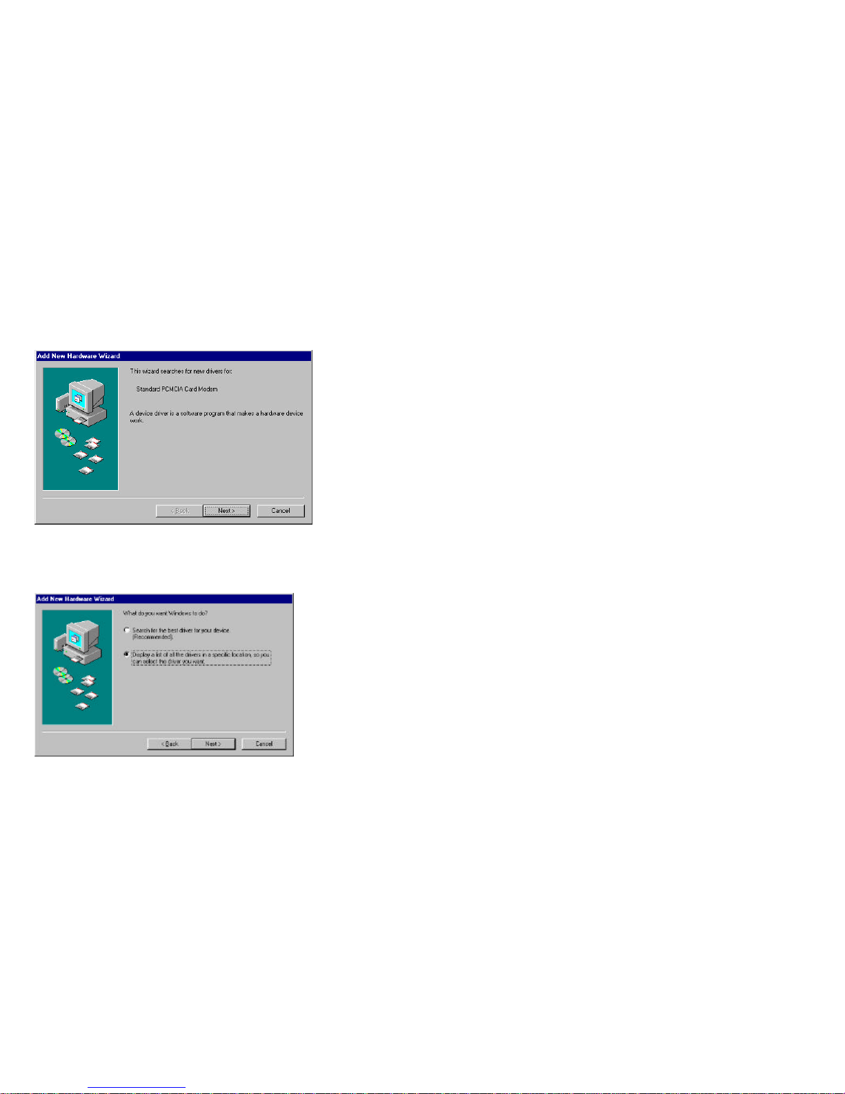
1. The first time you insert the card, the PC Card Wizard should open (see
figure below).
2. Press the “Cancel” button to exit the installation or “Next” to continue. The
next window as shown below is displayed.
3. Check the “Display a list of all the drivers in a specific location, so you can
select the driver you want” command box and press the “Next” button.
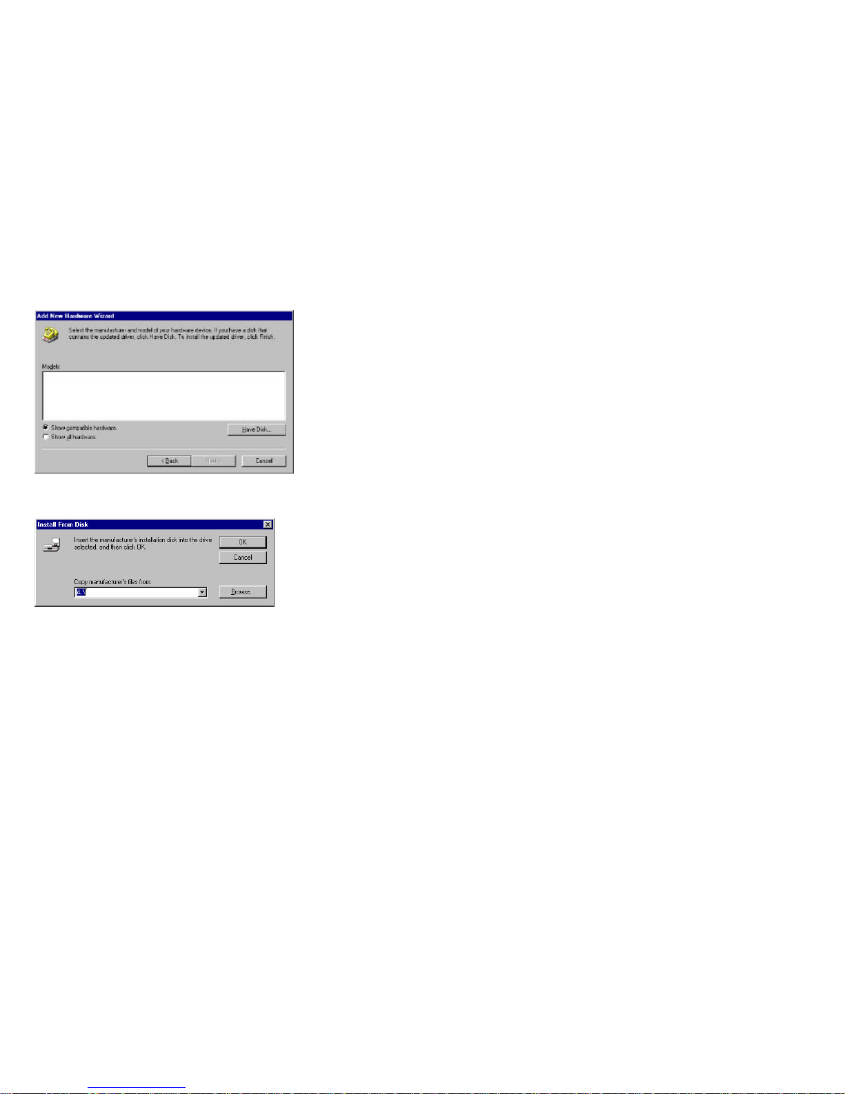
4. The driver location selection screen is displayed. Insert the drivers diskette
into drive A and press the “Have Disk…” button.
Page 16
12
5. The window in the figure below is displayed and indicates the driver found
by the system (in most newly purchased Windows system the driver for
Globewave PC card will be found).
6. Verify that the A:\ drive is specified in the “Copy manufacturer’s files from”
box and press the “OK” button. The “GlobeWave Com.plete PC Card
Celphone” will appear in the “Models” box.
Page 17
13
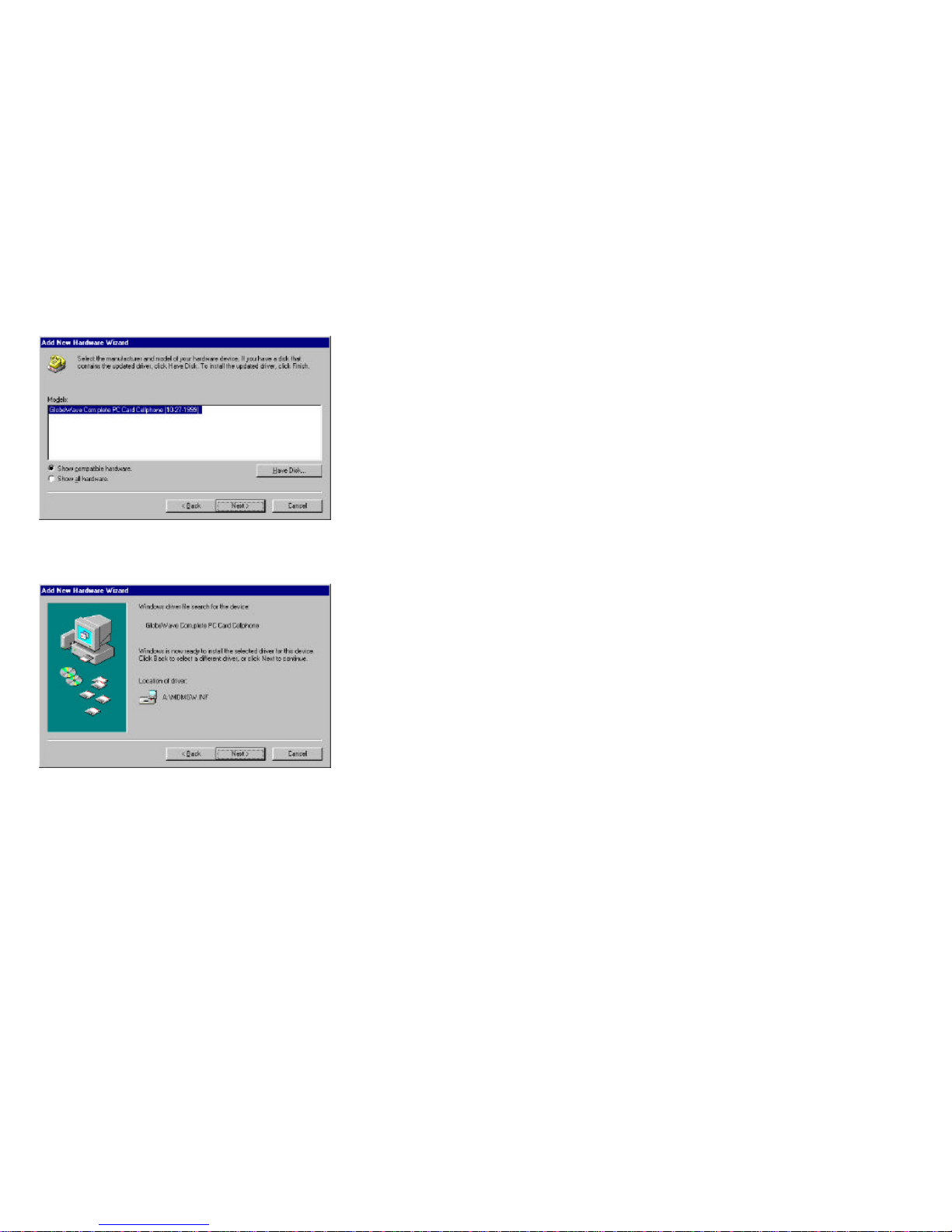
7. Press the “Next” button. A window carrying the identification of the card
“GlobeWave Com.plete PC Card Cellphone” and the name of the file driver
(MDMGW.INF) will appear.
11. Press the “Next” button. The ending window will appear. Press the “Finish”
button.
Page 18
14
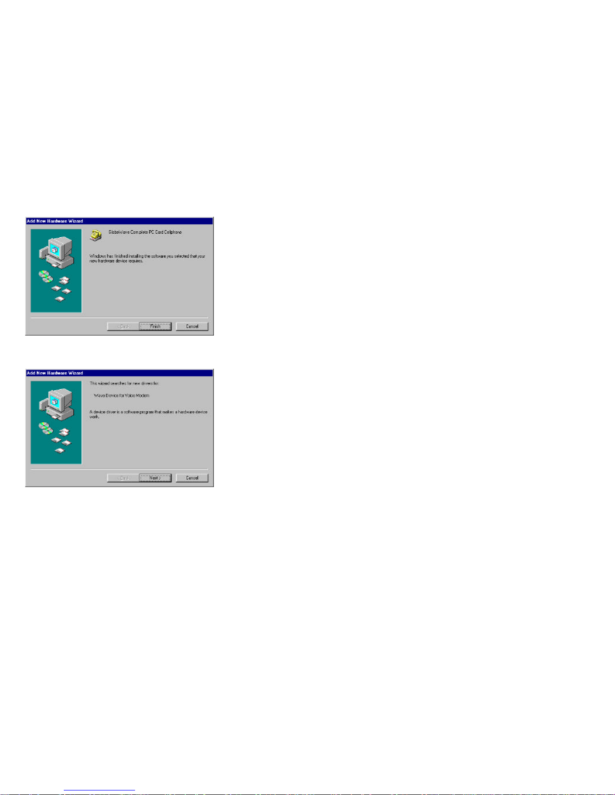
12. A window indicating that the system will look for a voice modem is
displayed. Press the “Next” button.
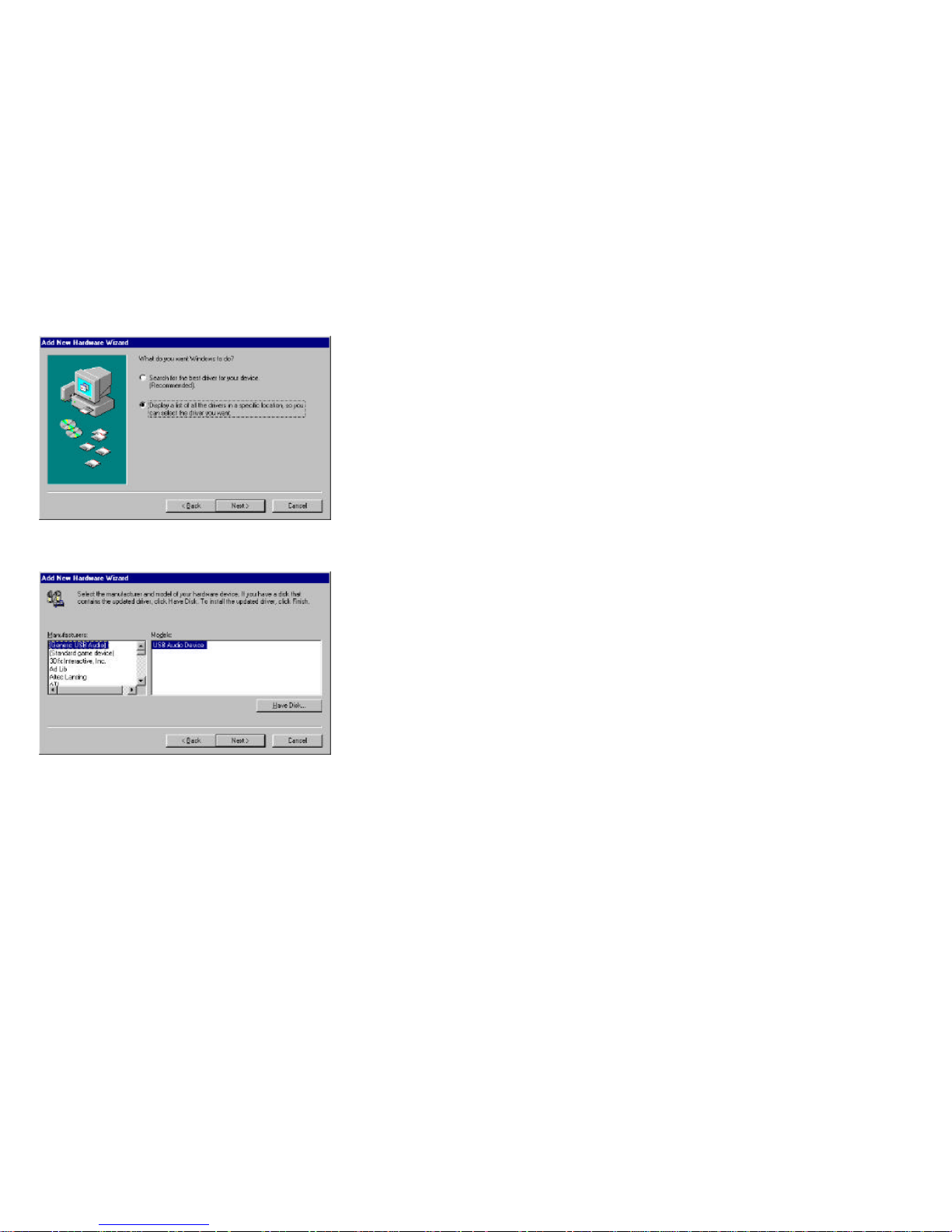
13. Check the “Display a list of all the drivers in a specific location, so you can
select the driver you want” command box and press the “Next” button.
Page 19
15
14. After the search the system will come with a manufacturer and model name
(see figure below).
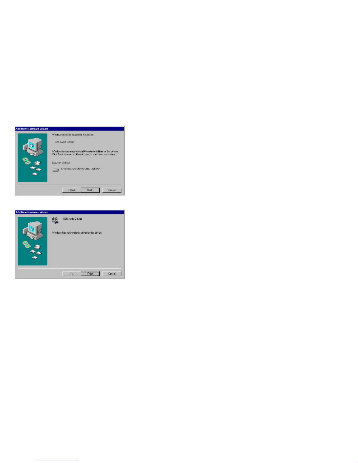
15. Press the “Next” button. A window indicating the name and location of the
driver file is displayed.
Page 20
16
16. Press the “Next” button. The ending window for the installation is displayed.
17. Press the “Finish” button to complete the installation.
Ejecting the Com.plete PC Card:
1. Make sure all software accessing the PC Card has been closed. This also
includes software that has instructed the PC Card to switch to Auto Answer
mode.
2. Press the PCMCIA eject button.
3. Remove the card when it is released.
Page 21
17
Your Com.plete PC Card is now ready to work with your communication
software. However, for cellular data operation , you must still activate your PC
Card to work over the cellular network.
Loading the Com.plete PC Card User Software:
Your Com.plete PC Card user’s software includes:
• Activation Software - Used to activate the card for cellular use
• Dialer Software - Used to dial cellular voice calls
• Status Software - Advanced cellular status software
• Firmware Download - To update card's firmware
Using Windows 95/98 and Windows NT:
1. Insert the disk labeled “Setup/User Software Windows 95 Disk 1 of 3 ” into
your floppy disk drive.
2. Use the Windows 95 “Start” button and select “Run”.
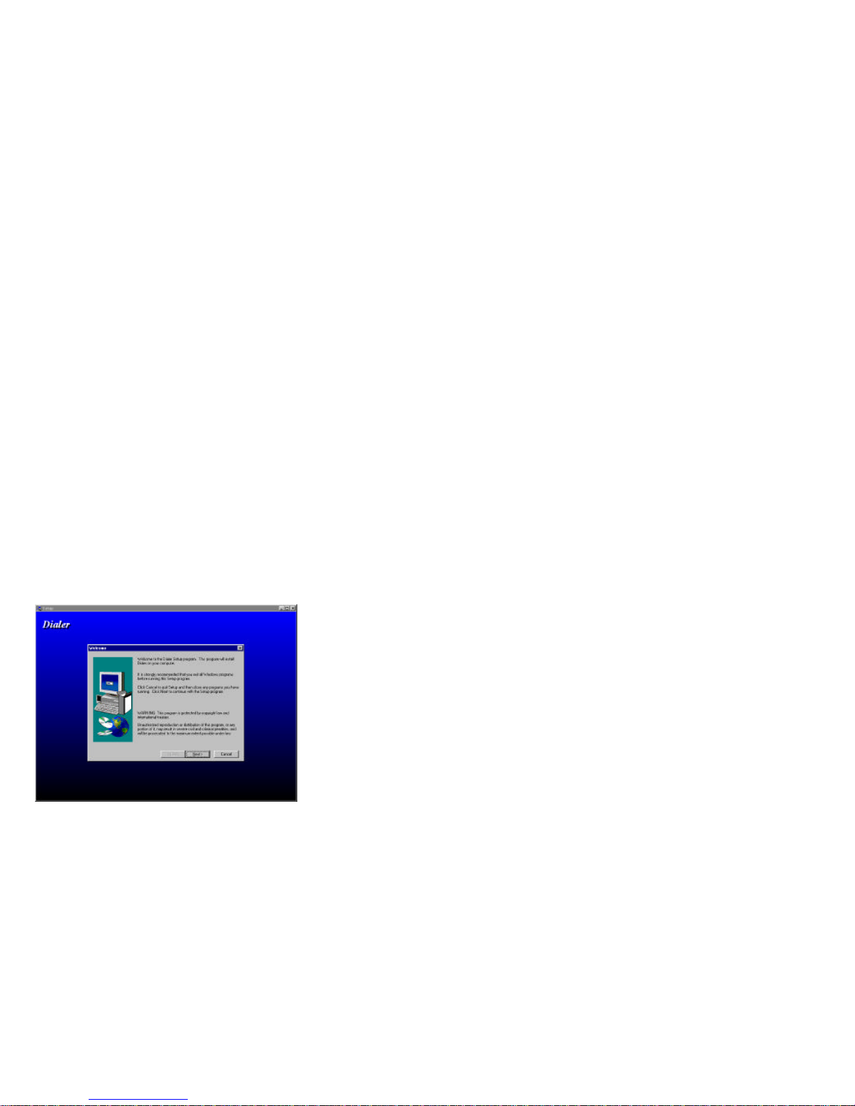
3. Type or select by the “Browse” button “A:\Setup”. The “Dialer” setup
screen will be displayed.
4. Press the “Next” button to continue the installation, or the “Cancel” button
to exit the installation. The “Choose Destination Location” window will be
displayed.
Page 22
18
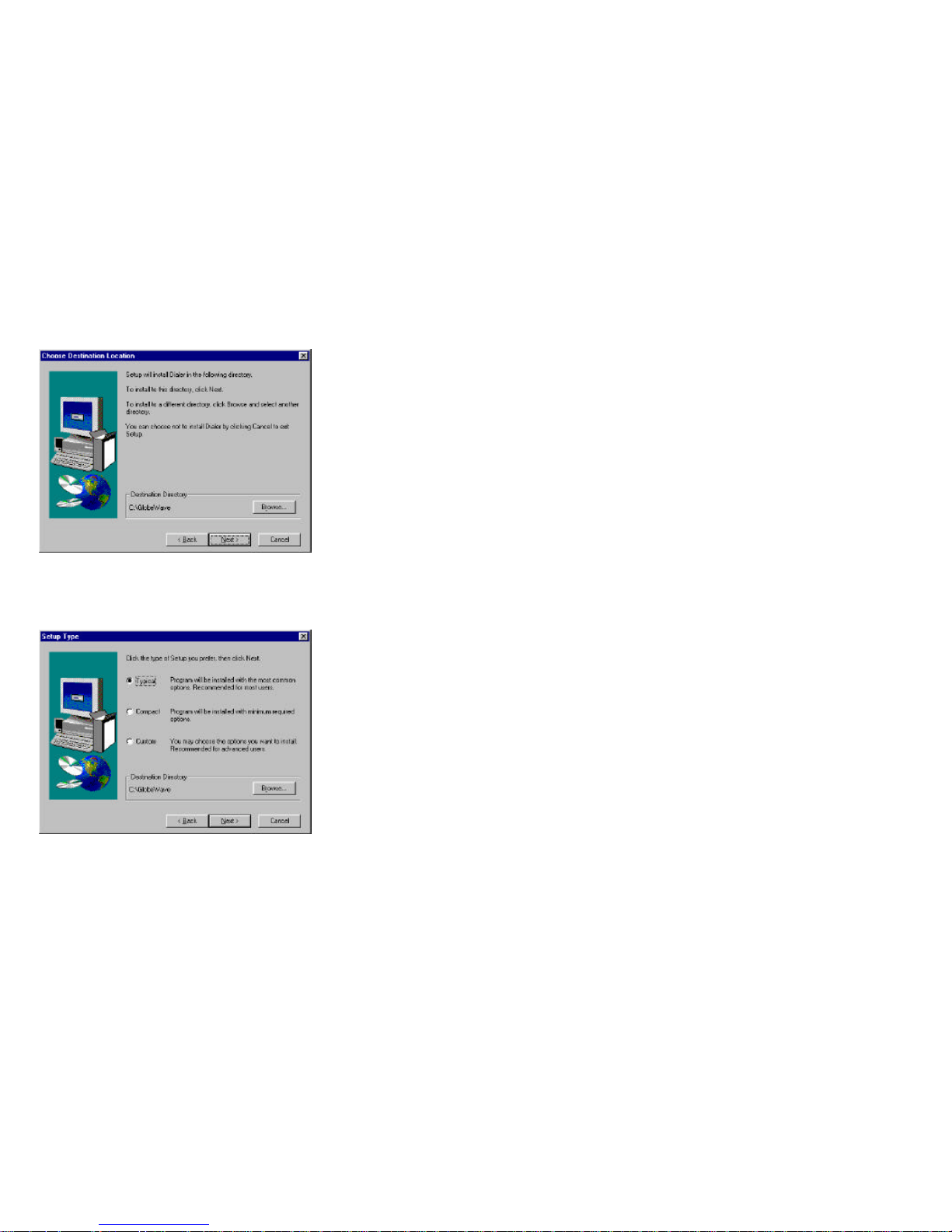
5. The software is installed by default to <c:\GlobeWave> directory. If you wish
to install it into another directory, press the “Browse” button and select a
new directory to install the software in.
6. Press the “Next” button. The “Setup Type” window will be displayed.
7. Three types of setup are available:
One. Typical – installs the “Dialer” software and “Activate” service
program.
Page 23
19
Two. Compact – installs only the “Dialer” software.
Three. Custom – allows you to choose whether or not to install the
“Activate” and “Status” service programs (the “Dialer” box should
always be checked).
Check the command box of the setup type you wish to carry out and then
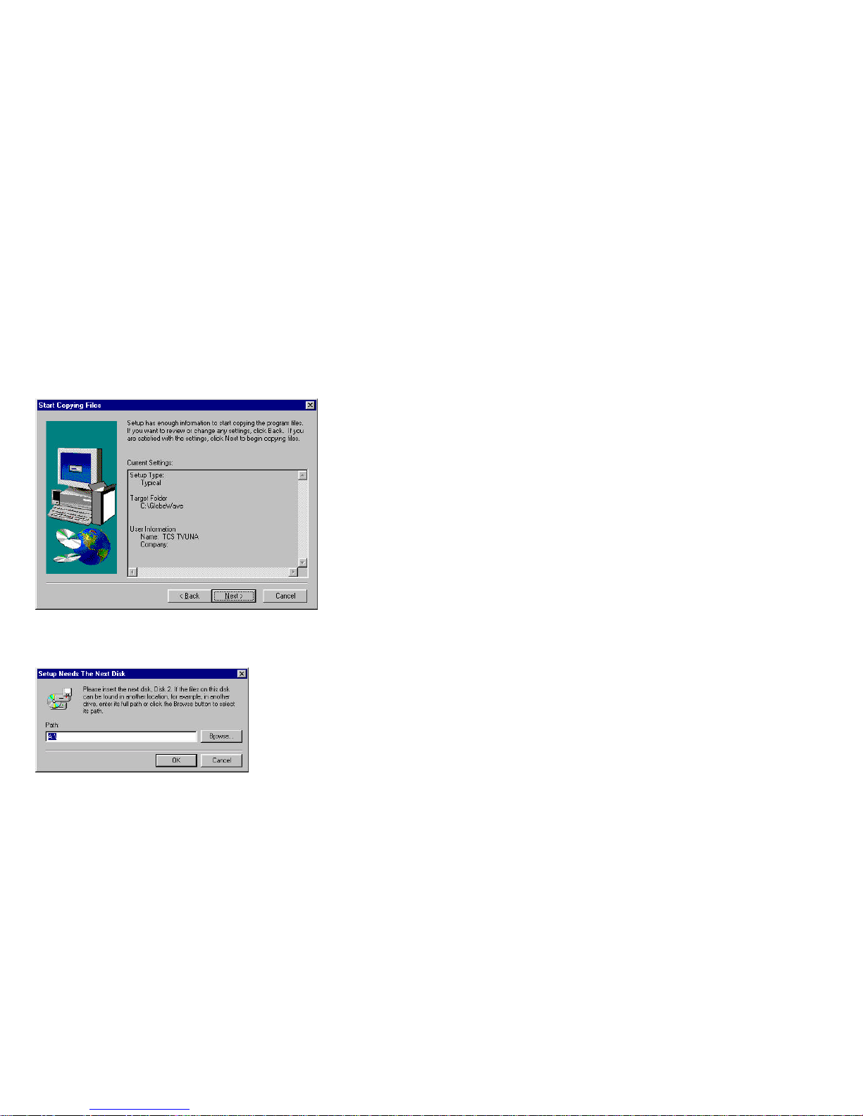
press the “Next” button. The “Start Copying Files” window is displayed. The
“Current Settings” settings area shows the settings you selected.
15. Press the “Next” button to continue the installation.
9. Setup starts copying files and installing the Dialer. Throughout the
installation setup will prompt you to replace the diskette (see figure below).
Replace the diskette as required and press the “OK” button.
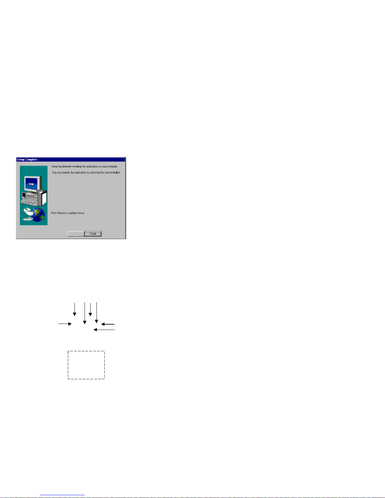
10. At the end of the installation the “Complete Setup” window is displayed.
Page 24
20
11. Press the “Finish” button to complete the installation. The system completes
the installation and adds three new icons on the task bar at the bottom righthad corner of the screen.
12. Your user software is now loaded and ready for use and the “Dialer” icon is
added to your computer’s screen.
Running and Using Dialer
1. Double-click one of the three icons on the task bar. The “Dialer” window
will be displayed.
2. The three added icons are inactive as long as the “Dialer” screen is open.
Once the “Dialer” screen is minimized, the three icons become active (see
Task Bar Icons for details).
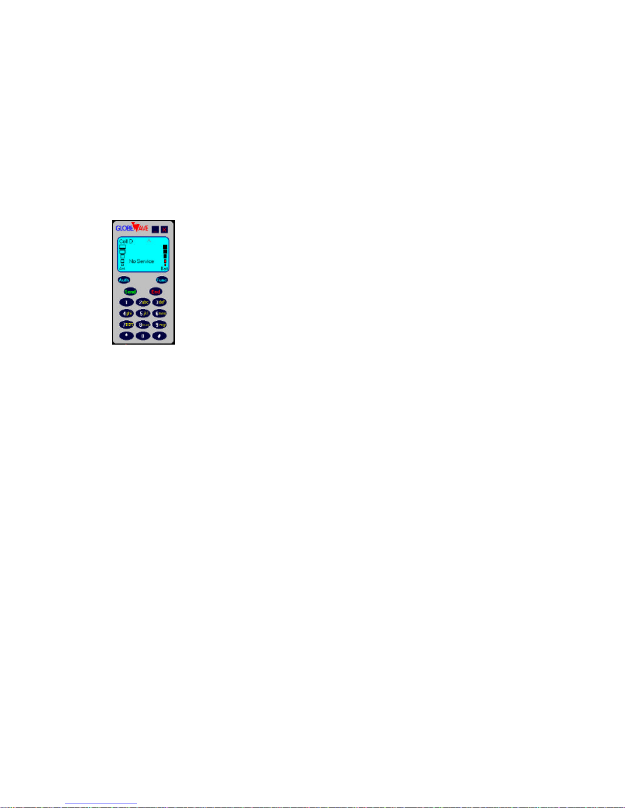
3. The “Dialer” main window is shown below:
1
234
567
Page 25
21
5. The “Dialer” window is used for dialing, answering an incoming call,
retrieving information about the PC card and open the functional windows.
6. The window’s displays and command buttons are as follows:
1) Mode label:
Cell – cellular phone
Line – line phone
Cell D – cellular modem
Line D – Line modem
2) Signal Strength display – displays the level of the received signal.
Visible only in the cellular modes.
3) Power display – displays the computer’s battery power.
4) GlobeWave label – shows the status of the PC card communication:
No Service – when cellular service is not available for the card in the
cellular modes
Incoming call – indicates an incoming call (together with a sound or
beep)
Number – when a number is dialed, it is displayed in this place
Connected – when connection with the dialed number or the incoming
call is established.
5) Dialing label – appears after the “Send” button is pressed and is
displayed until connection is established.
6) Roaming label – this label is displayed in cellular modes, when the
service is provided by other than the home carrier.
7) System label – indicates the current used system, A or B.
8) Connection symbol – appears when connection with the other party is
established.
9) Close button – press to exit the dialer.
Page 26
22
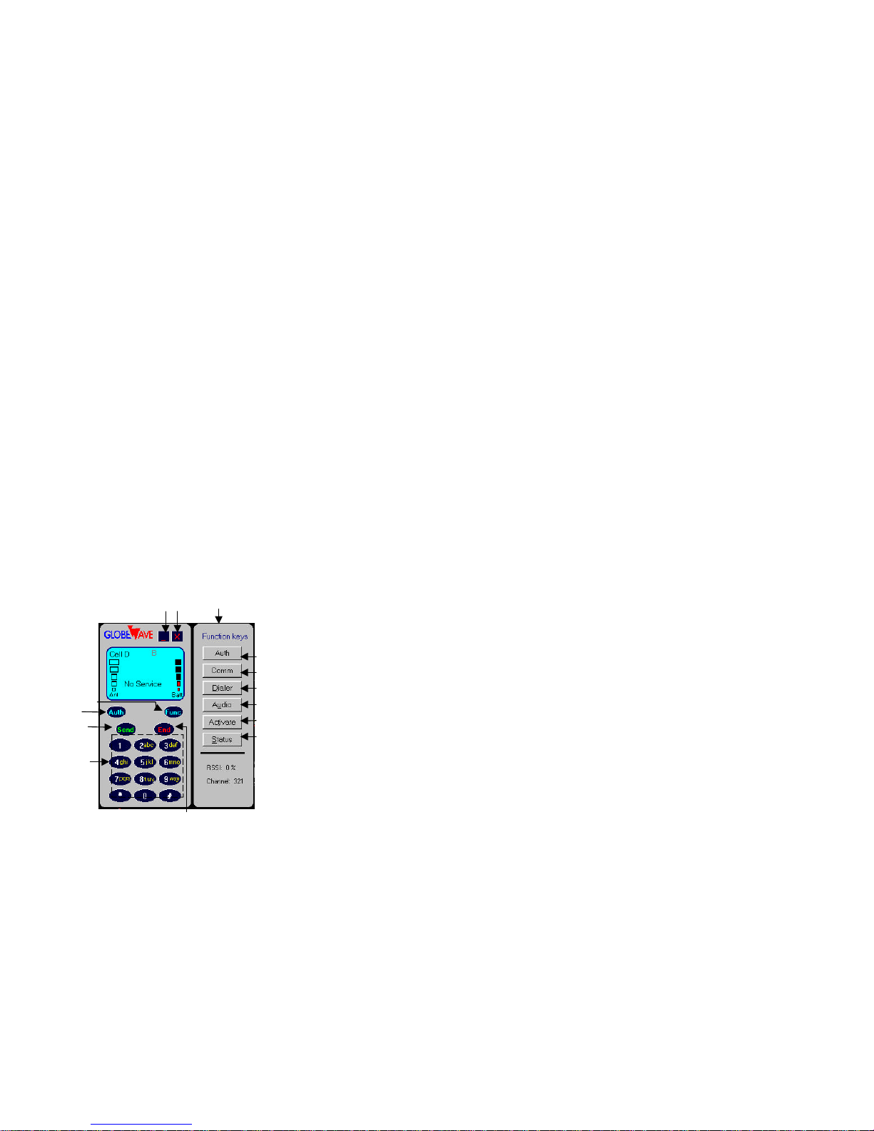
10) Minimize button – minimizes the “dialer” window and activates the task
bar icons.
11) Send – press to dial a number or to answer an incoming call.
12) End button – press to hang up.
13) Auth/Clr – a two functions button:
- Auth – used only in cellular modes to send the authentication
number. After sending the authentication number the button
switches to Clr.
- Clr – clears the last dialed number.
14) Func button – opens and closes the “functions” window.
15) Number keys – serve for dialing a number.
7. The functions windows is opened by pressing on the “Func” button (see
figure below):
16) Auth – opens the authentication window.
17) Comm – opens the communication window
18) Dialer – opens the Dialer Setup window.
19) Audio – Opens the audio window.
20) Activate – opens the Activate window (only if the Activate service
program was installed).
21) Status – opens the Status window (only if the Status service program
was installed).
131115
Function
window
91014
16
19
20
Page 27

23
Activating your Com.plete PC Card for Cellular service:
Since your Com.plete PC Card contains a cellular phone, the first thing to do
once you have installed the Com.plete PC Card driver and activation software is
activate your card for cellular usage.
The Activation software is designed to be a fast and simple tool to ease you
through this process, but there are a few items to prepare prior to running the
activation software.
• Make sure that the PCMCIA slot is enabled and the card drivers are installed
properly on your computer. These should be installed and pre-configured in
your computer already. If not, consult the documentation provided with your
computer on how to enable the PCMCIA slot.
• Run Windows, if not already running.
• Slide the Com.plete PC Card (front label up) into the PCMCIA slot of your
host computer until it is fully seated.
• Wait for the Card and Socket Services to recognize and initialize the card.
Usually you will get a "beep" and/or a popup window indicating the
successful configuration of your card. If you are not familiar with the
operation of your PCMCIA drivers, please consult the documentation
provided with your computer for additional information.
• On the “Dialer” window’ press the “Func” button.
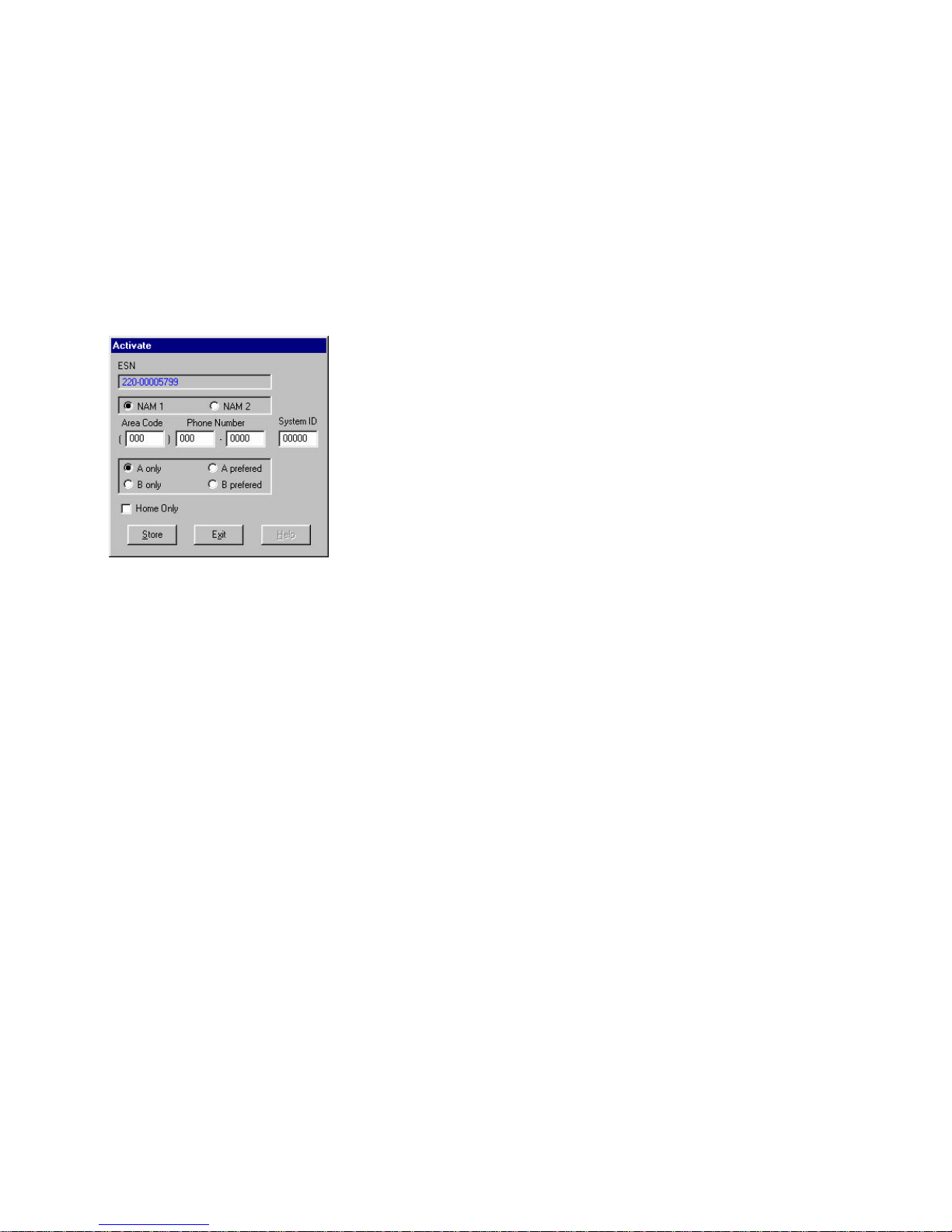
• Click the “Activate” button on the “functions” window. The activate screen
will pop-up (see figure below).
Page 28
24
Page 29

25
Using and Understanding the Activation Software:
The activation software is provided to be a simple cellular phone programming
interface. There are five (5) important pieces of information either provided by
or to be programmed on the activation utility:
• ESN (Electronic Serial Number)
• NAM Selection
• Cellular Phone Number
• System ID
• System Service Selection
The software locates the card comm port when it is started. If the card is not
found a message appears and the software is terminated. If the software finds the
card, the comm port number can be seen on the communication window.
The activation software then reads the Electronic Serial Number (ESN) of the
card and displays it. This number is electronically stored in your PC Card’s
memory, and is the only number required by the cellular service provider, since it
identifies the specific card’s manufacturer and serial number. The remaining
fields are left to input by you, based on information you receive from the cellular
service provider. These fields are:
• Cellular phone number - a 10 digit number consisting of 3 digits area code
and 7 digits phone number
• System ID - a 5 digit home cellular service identifier
• System select: Click on the “system select” button matching the carrier of
your choice. Available options are:
A only: The Com.plete PC Card will register with Carrier A only. If Carrier A
is unavailable in this particular area, "No Service" will be indicated and
cellular calls will be disabled
B only: The Com.plete PC Card will register with Carrier B only. If Carrier
B is unavailable in this particular area, "No Service" will be indicated and
cellular calls will be disabled
A preferred: The Com.plete PC Card will try to register with Carrier A first.
If not available, it will alternately try Carrier B. If both Carriers are
unavailable in this particular area, "No Service" will be indicated and cellular
calls will be disabled
B preferred: The Com.plete PC Card will try to register with Carrier B first.
If not available, it will alternately try Carrier A. If both Carriers are
Page 30

26
unavailable in this particular area, "No Service" will be indicated and cellular
calls will be disabled
Note: If the Card registers with the "non-preferred" carrier, you might
eventually get a recorded message anytime you try to place a call. This
message will give you more information on how to get service for this carrier.
• Home Only checkbox, Click, if you want to use your Com.plete PC Card
only within your home service area and disable roaming to avoid possible
roaming charges. Ask your service provider for a map indicating your home
area range.
Programming Your PC Card For Cellular Service
Once you have started the Com.plete PC Card Activation software, you are ready
to program your PC Card. You will need to contact a cellular service provider to
obtain your phone number and other pertinent information programmable on the
PC Card.
The activation software will show the data for the NAM1 (the first phone number
entry). The first time you program your PC Card, these boxes should either be
blank or read zeros (0). The remaining information is given by your cellular
service provider and should be programmed in the appropriate fields.
The cellular carrier will ask you for the PC Card’s (or they will say Cellular
Phone) Electronic Serial Number (ESN). This number combined with the
cellular phone number they provide you make up your electronic phone number
on the AMPS Cellular Network.
Page 31

1.
Card (Phone.)
2. Give the cellular provider the PC Card’s Electronic Serial Number (ESN)
3. Select the “NAM 1”
4.
it in the Area Code and Phone Number boxes on the screen.
5. Ask the Cellular Service Provider for their System ID and System Selection
(A or B) and enter into them the appropriate boxes.
Once the phone number, system
“Store
7. Exit” button to leave the Activation Program. You are now ready
NOTE: If you would like to program a second phone number into your PC Card,
Page 32
28
Using the Dialer
Making a Call
1. Verify that the PC Card is in the desired mode.
2. Type in the number by pressing the number keys. To correct or change the
number, use the “Clr” button.
3. Press the “Send” button to dial the number.
4. To terminate the call and hang-up press the “End” button.
Answering an Incoming Call
1. Verify that the card is in the desired mode.
2. Press the “Send” button.
3. To terminate the call and hang-up press the “End” button.
Setting the Authentication Number
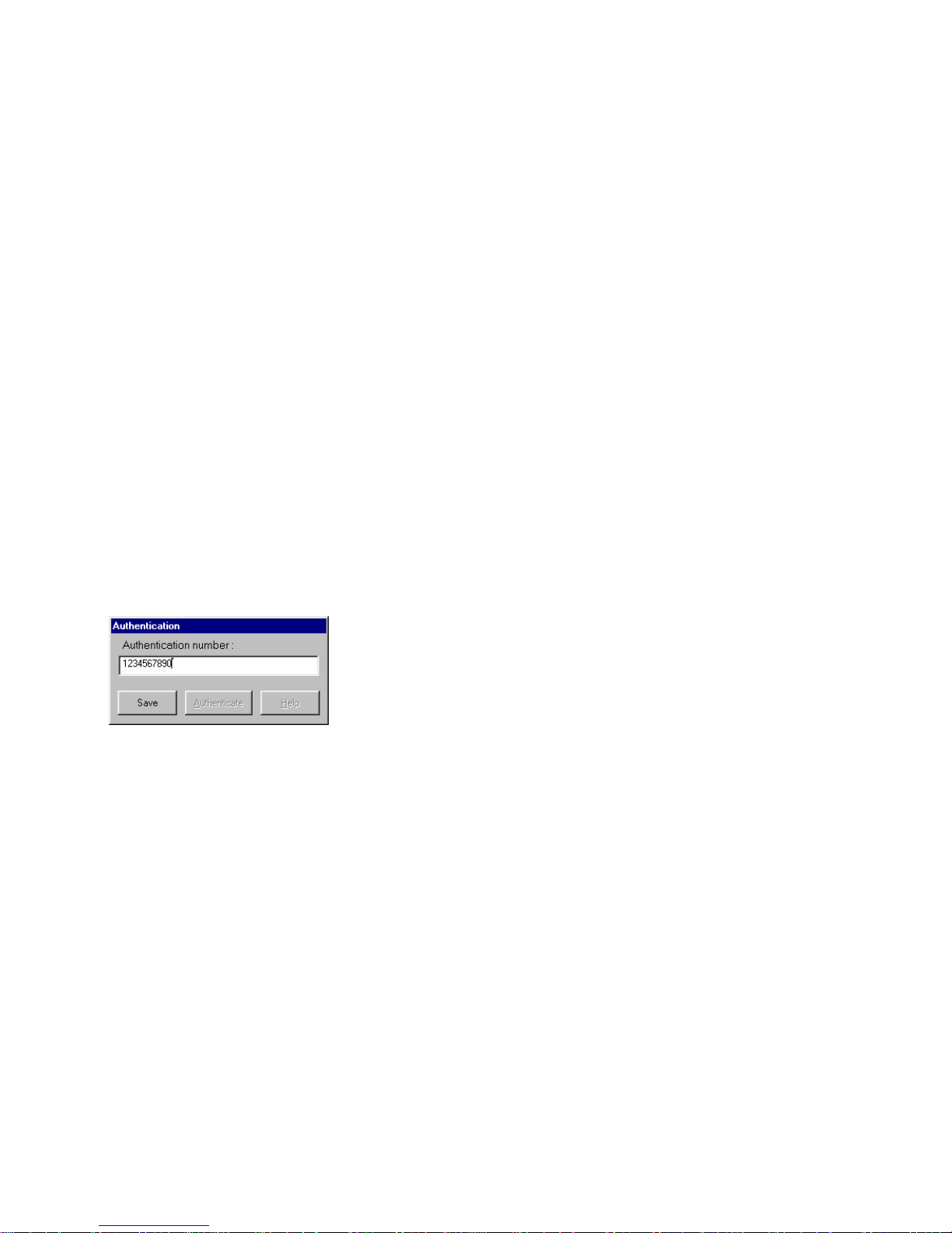
1. Press the “Func” button to open the “Functions” window.
2. Press the “Auth” button on the “functions” window. The “Authentication”
dialog box is opened (see the figure below)
3. If the “Dialer” window is minimized, you can click the right button of the
mouse on one of the icons on the task bar and select “Authentication” from
the pop-up menu.
4. Type in or edit the authentication number and press the “Save” button.
5. Verify that you are in a cellular mode.
6. To dial the authentication number, press the “Auth” button on the “dialer”
window, or open the “Authentication” diaog box and press the
“Authenticate” button.
7. Press the “Close” button to close the “Authentication” dialog box.
Page 33
29
Setting the Communication Options
1. Press the “Func” button to open the “Functions” window.
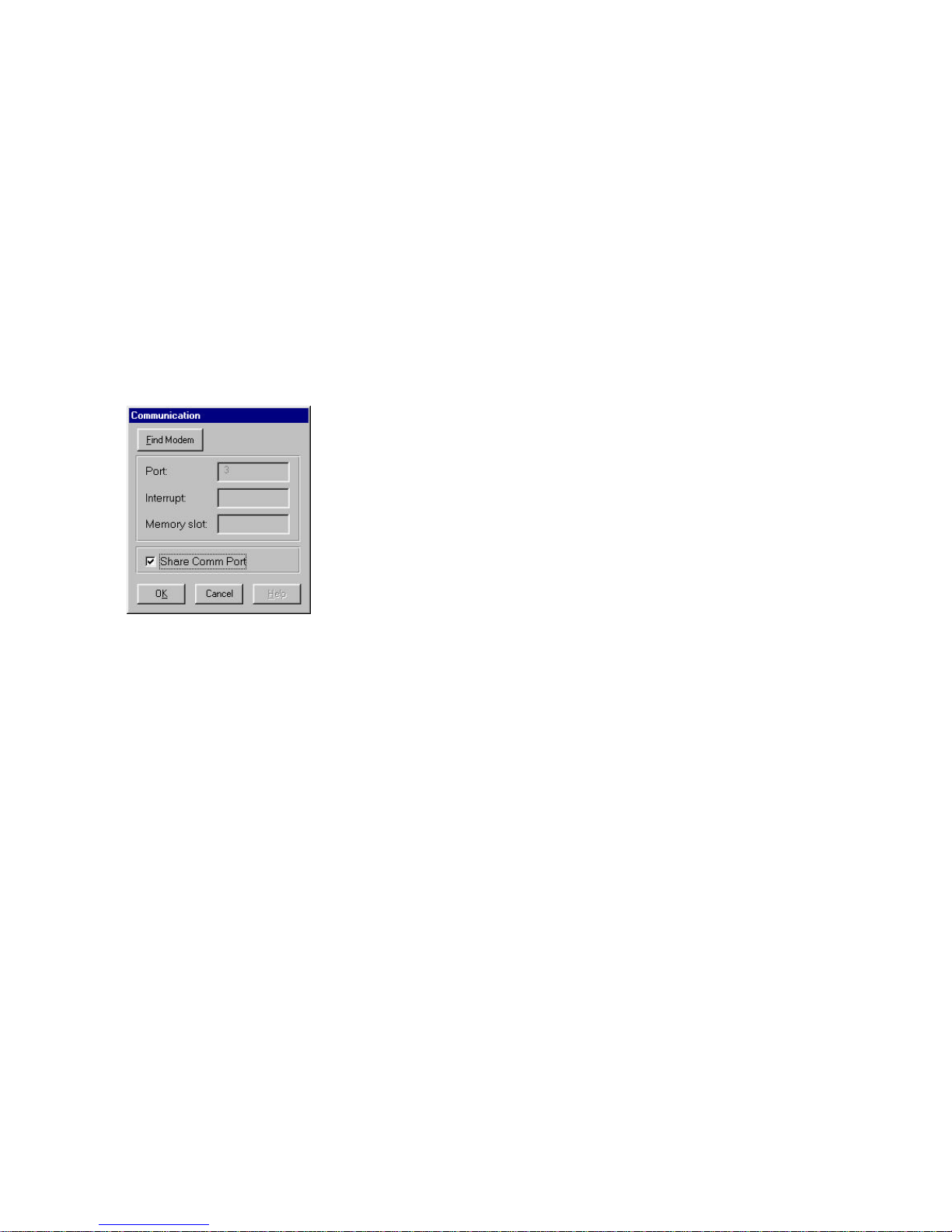
2. Press the “Comm” button on the “functions” window. The “Communication”
dialog box is opened (see the figure below)
3. If the “Dialer” window is minimized, you can click the right button of the
mouse on one of the icons on the task bar and select “Authentication” from
the pop-up menu.
4. Press the “Find Modem” button in order to scan the computer’s ports and
locate the Com.plete PC Card.
5. Check the “Share Comm Port” box to retrieve the PC card information when
the “Dialer” window is minimized (the icons on the task bar are active).
Setting the Dialer Options
1. Press the “Func” button to open the “Functions” window.
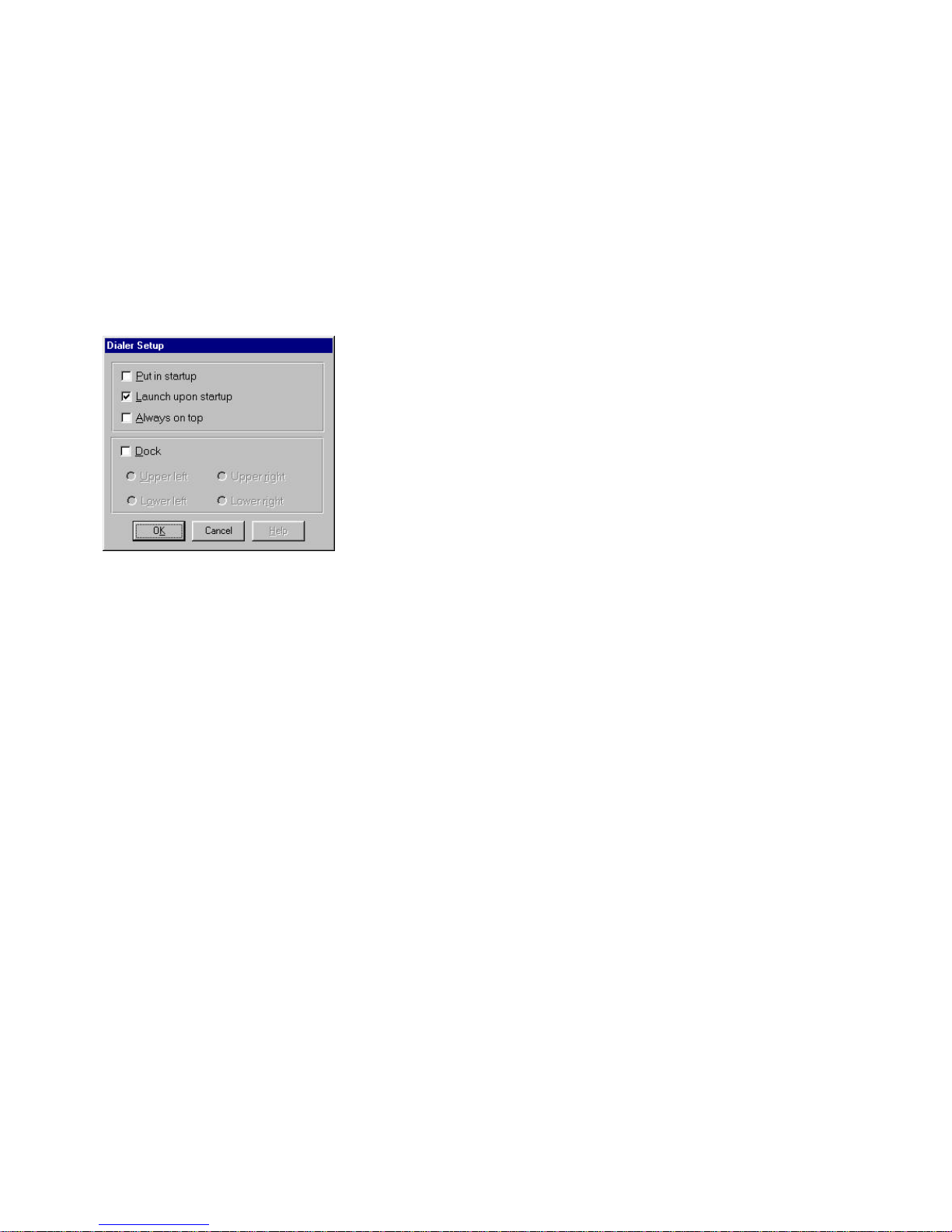
2. Press the “Dialer” button on the “functions” window. The “Dialer Setup”
dialog box is opened (see the figure below)
3. If the “Dialer” window is minimized, you can click the right button of the
mouse on one of the icons on the task bar and select “Dialer” from the popup menu.
Page 34
30
4. Check the “Put in startup” box to add the “dialer” to the startup menu.
Uncheck the box to remove the “Dialer” from the startup menu.
When the “dialer” is added to the startup menu, it will start automatically
whenever the Windows system is started.
5. Check the “Launch upon startup” box to open the “Dialer” window every
time you start the software. Uncheck the box in order to display and activate
the task bar icons when the software is initiated.
6. Check the “Always on top” box to force the “Dialer” window to be always
displayed above any other active window.
7. Check the “Dock” box, in order to dock the “Dialer” window to one corner.
The check boxes under the “Dock” box are illuminated and become active.
Select the box of the corner you wish to dock the window into. Once you
selected a corner and pressed the “OK” button, the “Dialer” window will be
docked to the desired corner and you will not be able to drag it from there.
8. Press the “OK” button to confirm and activate your choices.
Setting the Audio Options
1. Press the “Func” button to open the “Functions” window.
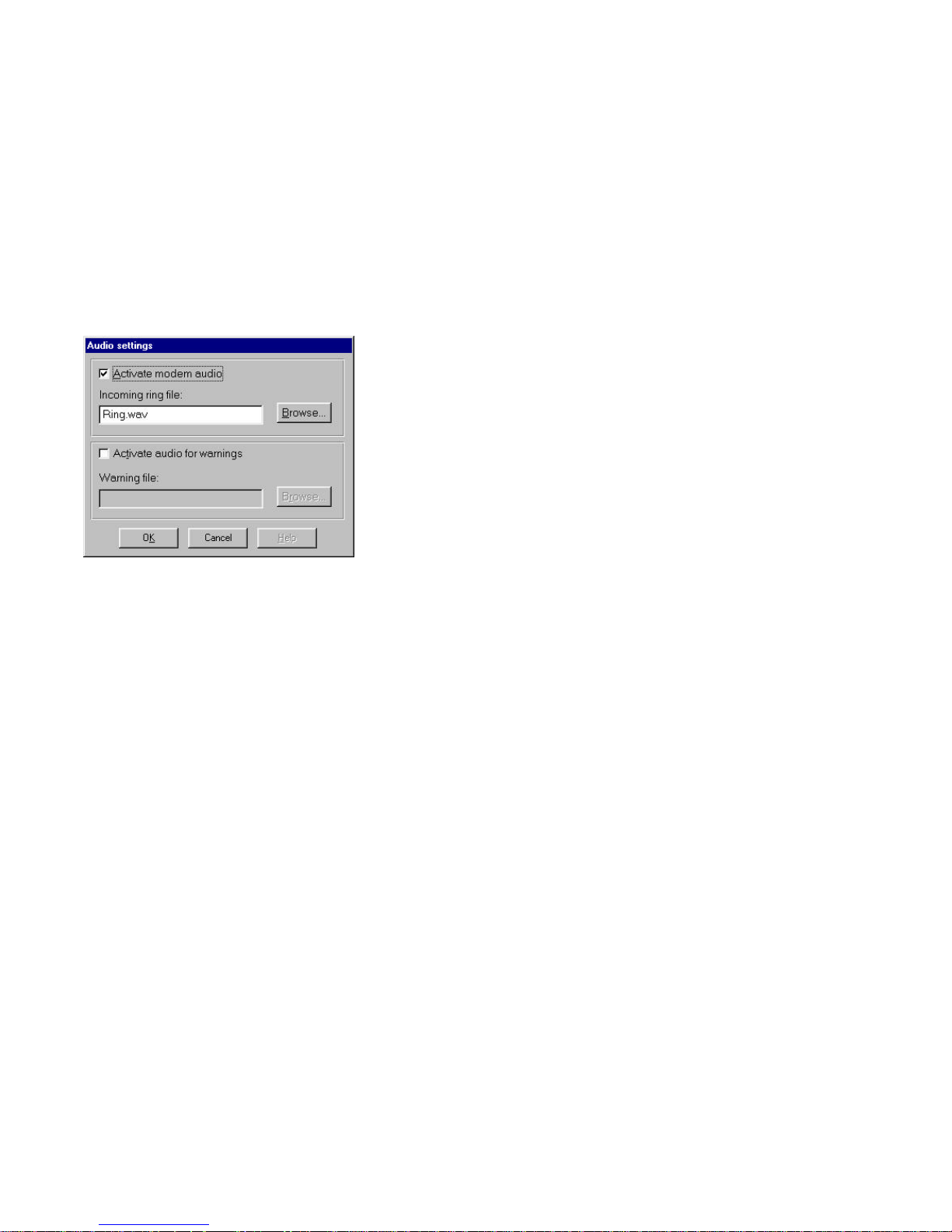
2. Press the “Audio” button on the “functions” window. The “Audio Setting”
dialog box is opened (see the figure below)
3. If the “Dialer” window is minimized, you can click the right button of the
mouse on one of the icons on the task bar and select “Audio” from the popup menu.
Page 35
31
4. To select a wav file that will be played when an incoming call is detected,
check the “Activate modem audio” box. Type in the name of the wav file and
its path in the box, or select a file using the “Browse…” button.
5. To select a wav file that will be played on low battery power or low signal
strength warning, check the “Activate audio for warning” box. Type in the
name of the wav file and its path in the box, or select a file using the
“Browse…” button.
6. Press the “OK” button to confirm your choices and close the dialog box.
Page 36
32
The Status Window
1. Press the “Func” button to open the “Functions” window.
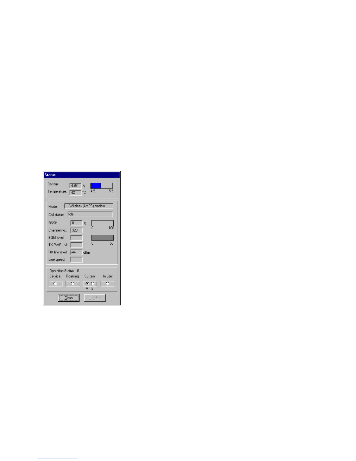
2. Press the “Status” button on the “functions” window. The “Status” dialog
box is opened (see the figure below)
3. If the “Dialer” window is minimized, you can click the right button of the
mouse on one of the icons on the task bar and select “Status” from the popup menu.
4. The status of various characteristics of the modem and communication are
displayed in this window.
Page 37

33
Task Bar Icons
When the dialer is initialized, three icons appear on the task bar. As long as the
“dialer” screen is active, these icons are inactive. Once the “Dialer” screen is
minimized these icons become active.
Mode Icon
The right icon can have one of the following shapes:
Clicking the icon with the left button of the mouse will restore the “Dialer”
screen and inactivate the task bar icons.
Clicking the icon with the right button of the mouse will open a pop-up menu,
which contains all the functions of the “Functions” menu.
The Signal Icon
The middle icon is the signal icon. When you point it with the mouse, a label
indicating the received signal level percentage will appear.
Clicking the icon with the left button of the mouse will restore the “Dialer”
screen and inactivate the task bar icons.
Clicking the icon with the right button of the mouse will open a pop-up menu,
which contains all the functions of the “Functions” menu.
Voice mode Icon - Switched
automatically when EarSet plugged in
Modem mode switched when
DAA (RJ11 connector) plugged in
Cellular mode Icon
Landline mode Icon
Page 38

34
The Battery Icon
The left icon is the battery icon. When you point it with the mouse, a label
indicating the battery voltage will appear.
Clicking the icon with the left button of the mouse will restore the “Dialer”
screen and inactivate the task bar icons.
Clicking the icon with the right button of the mouse will open a pop-up menu,
which contains all the functions of the “Functions” menu.
Page 39
35
Important Operational Information
Auto-Mode Switching Capability:
Your Com.plete PC Card comes set-up to automatically detect the type of call you
are placing. This is done to minimize or eliminate special hardware or software
set-ups for your PC Card. Depending on the connections made to your PC Card,
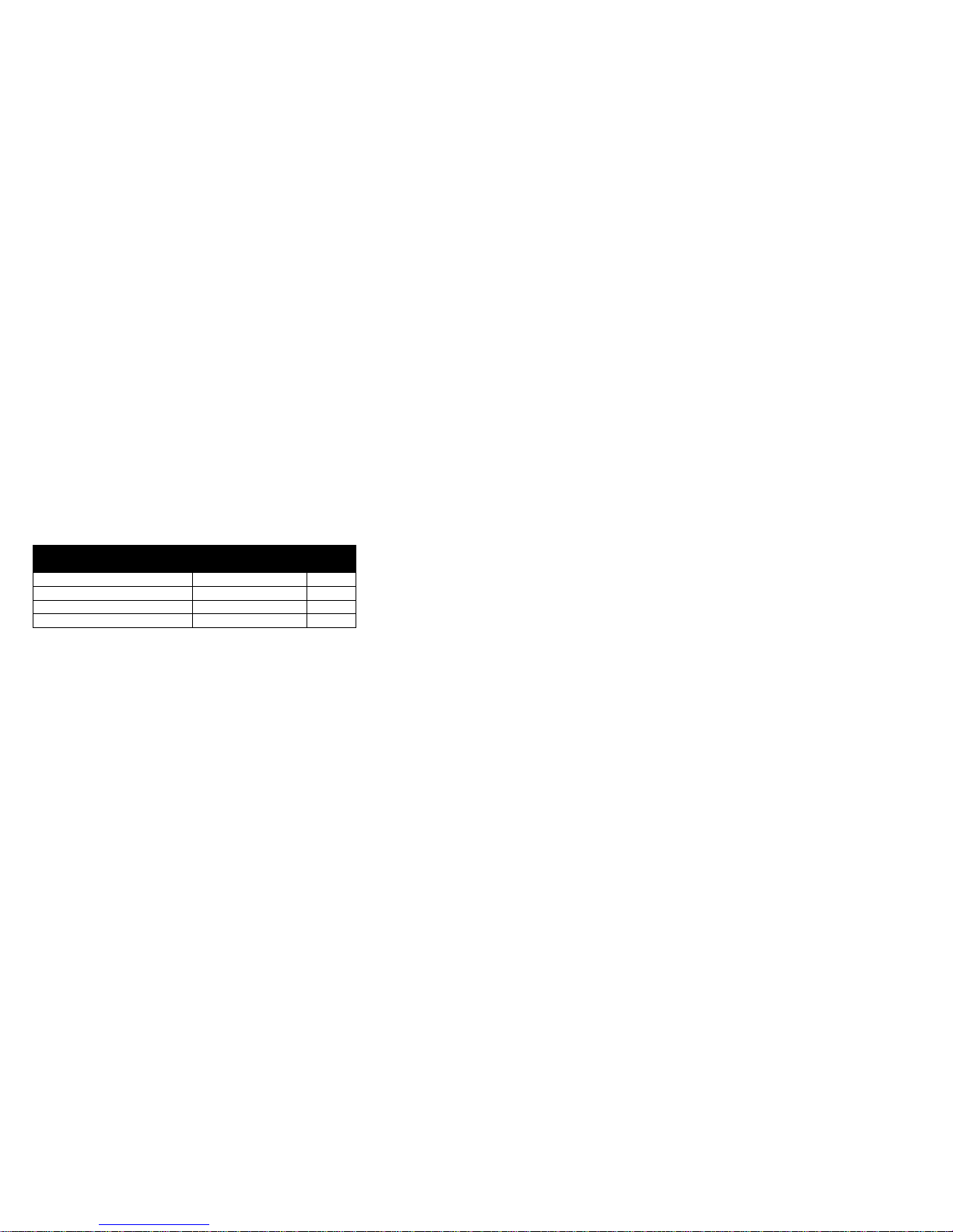
the card will switch automatically to one of four (4) different operational modes,
Cellular Data, Land-Based Data, Cellular Voice or Land-Based Voice. The
default modes are shown below:
AUTOMATIC MODE SWITCHING DEFAULTS
Accessories Communications
Mode
Mode
number
Antenna Only Cellular Data Mode 1
EarSet & Antenna Cellular Voice Mode 3
EarSet & Landline DAA Landline Voice Mode 2
Landline DAA only Landline Data Mode 0
In addition to the automatic mode defaults, several software definable optional
modes can be programmed into the PC Card. Please note that unless the
defaults are changed, the PC Card will operate only in the modes shown above.
Your Com.plete PC Card is equipped with several features designed to provide
simple and reliable cellular data and voice connections. Specifically, the PC
Card is equipped with a high performance ¼ wave cellular antenna, significant
cellular error correction and enhancement firmware, radio shielding, power
saving features and auto-mode selecting firmware. Unlike a standard cellular
phone, the cellular radio in your PC Card has been designed specifically for a
notebook or hand-held computing environment. In most cases, you will be in an
environment where good to excellent cellular coverage exists and should have no
problem sending and receiving cellular data. However, there are a few tips
provided below which, if followed, will further improve your cellular data
experience.
Page 40

36
Cellular Reception:
Your card’s antenna can be rotated and detached for removed positioning. Proper
use and placement of your antenna can enhance your cellular performance and
may be critical for sending and receiving cellular data in locations where you are
either far away from the nearest cellular switch or have some bulky obstructions
between you and the cellular switch. In all cases, we recommend the following
usage guidelines for your cellular antenna.
1. In most cases your antenna should be used directly plugged or into the PC
Card. You should always have the antenna pointing vertically towards the
ceiling/sky.
2. If you are indoors and have trouble in cellular communications, you should
locate the notebook or hand-held computer as close as possible to a window.
Radio signals do go through walls, but some of the signal strength is lost, so
it is always best to locate yourself near a window where signal degradation is
minimized.
3. If you are not receiving enough signal strength from the cellular network to
send or receive data, you may have some interference being generated from
your computer. In this case, you should remove the antenna and attach it to
the antenna extension cable, then plug the extension cable into your PC
Card. Positioning the antenna away from noisy sources like computers can
sometimes help improve your signal strength and therefore increase your
data throughput.
Page 41
37
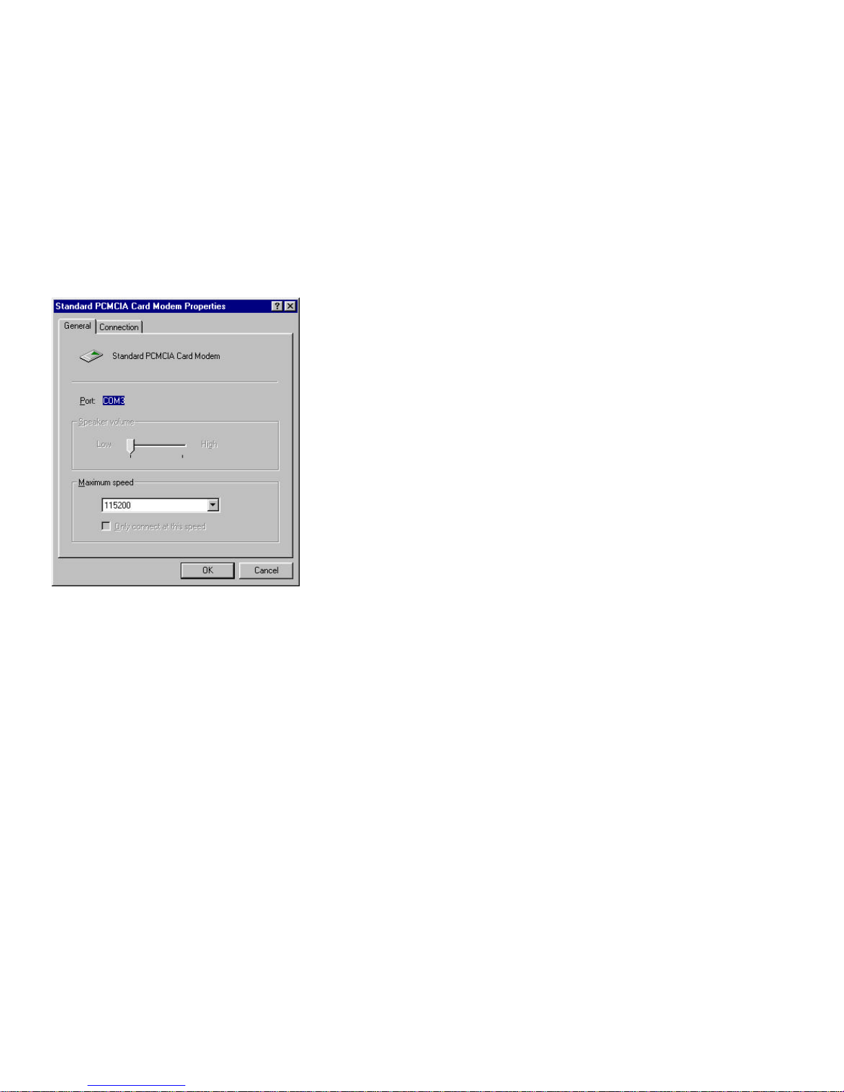
Setting up Windows For Cellular Data:
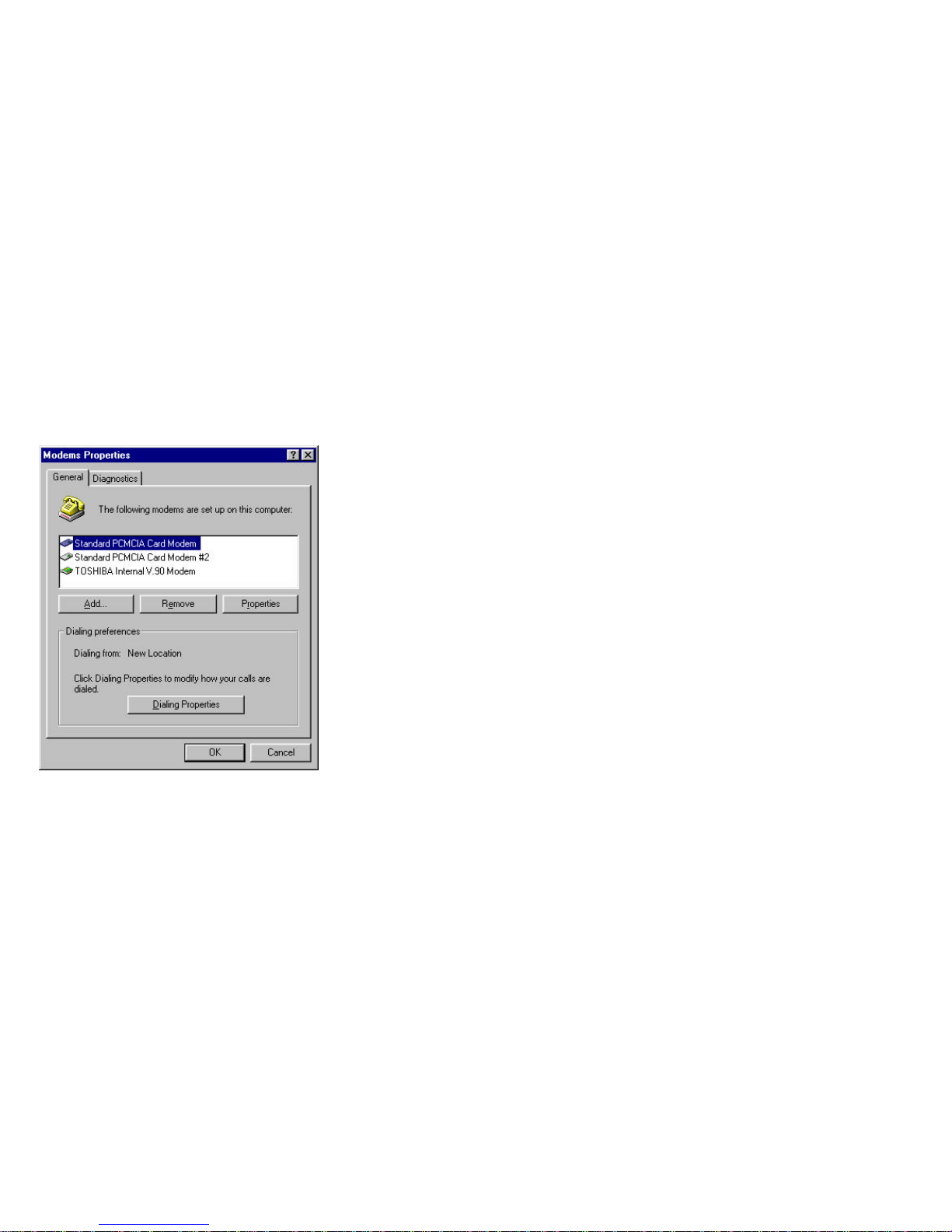
Your Com.plete PC Card needs to be set-up for proper use over the Cellular
network. This can be accomplished by modifying certain modem properties in
your Windows Control Panel Modem Set-Up Program:
1. Select the AMPS Modem as the active modem on your computer.
2. Select the “Properties” button on the modem set-up screen.
Page 42
38
3. Set your “Speaker Volume” to High.
4. Set your “Maximum Speed” to either 57600 or 115200.
5. Select the “Connection” tab.
Page 43
39
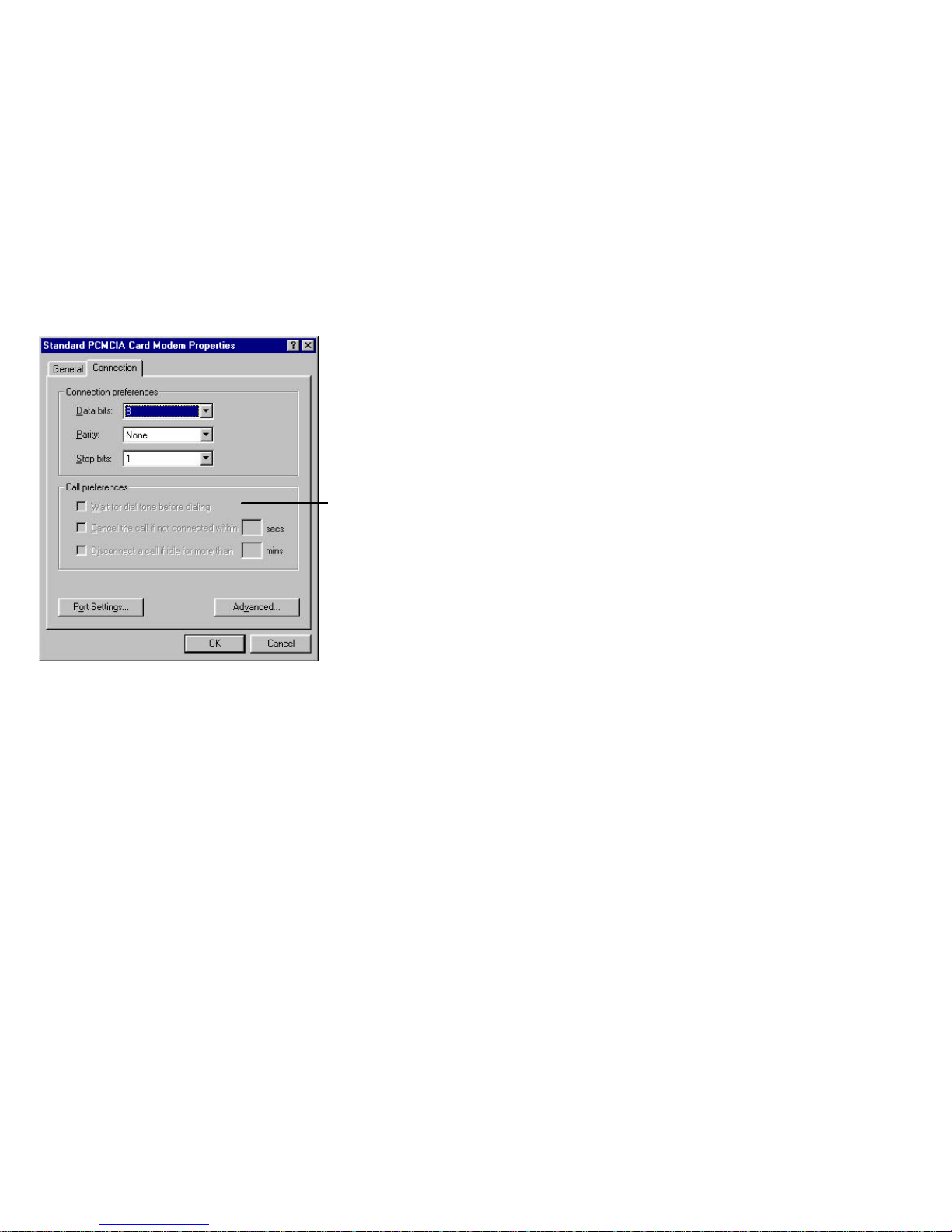
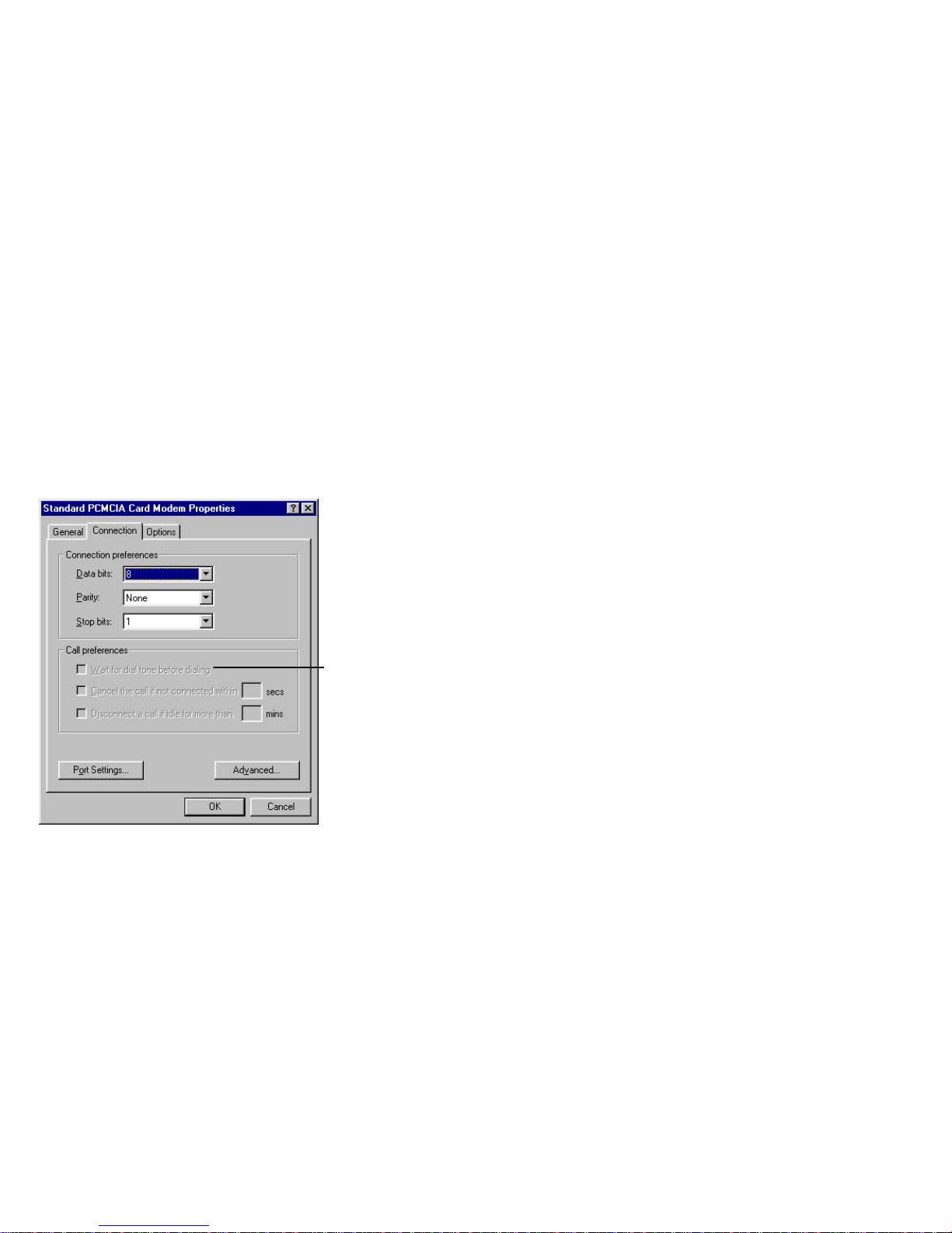
6. De-select the “Wait for dial tone before dialing” checkbox. This is done
because the cellular network does not use conventional land-based dial tones.
7. Set the “Cancel the call if not connected” time-out to 90-120 seconds.
8. Select the “Advanced” features button on your modem setup screen.
NOTE: For
cellular
connections,
this box
should
remain unchecked. For
land-based
connections,
the box must
be checked.
Page 44
40
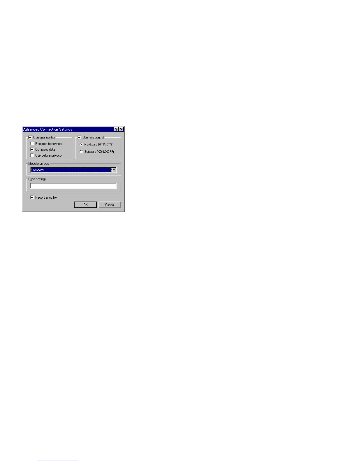
9. Make sure that “Use error correction” is check. “Compress data” must be
checked. However, “Use cellular protocol” is not necessary to check, but
may be used.
10. Make sure that “Use flow control” is checked. Make sure to use “Hardware
flow control,” not software flow control.
Page 45
41
Using Dial-Up Networking for Cellular Data Connections:
Most communications software programs are set-up to be used with a modem
connected to a land-based telephone line. Your Com.plete PC Card is equipped
to work with both land-based and cellular-based connections for sending and
receiving data and/or voice. While your PC Card is equipped with a variety of
error correcting protocols used for sending cellular data, Windows 95 and most
communications programs need to be modified to work optimally over the
cellular network.
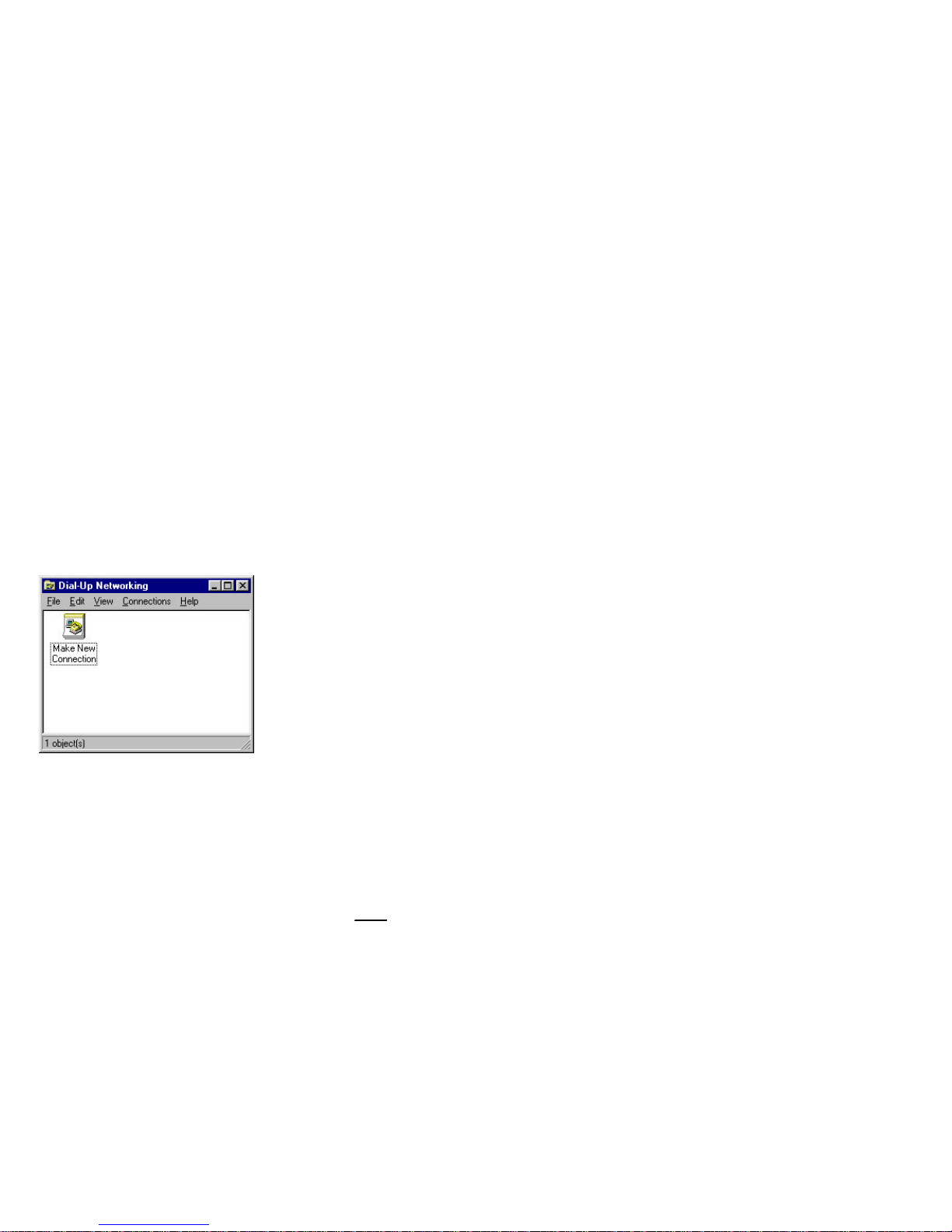
Most 32-bit Windows 95 communication programs use Windows “Dial-Up
Networking” as the method to establish a data connection. This section will
describe how best to set-up your connections for both land-based and cellularbased data.
Dial-Up Networking Windows 95 Screen
Setting Up Dial-Up Networking for Cellular Data Connections:
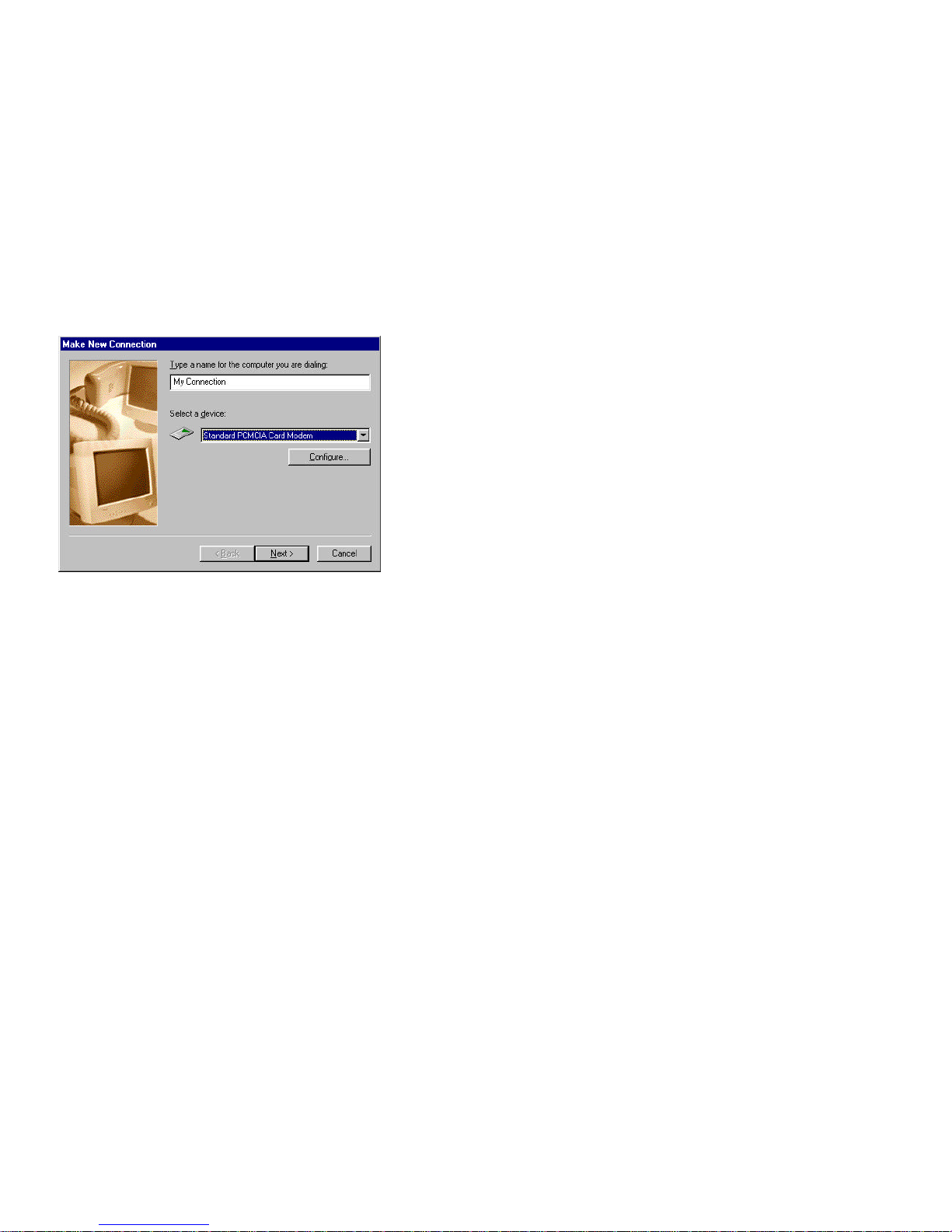
1. Double click the “Make New Connection” icon in the Dial-Up Networking
window, a “Make New Connection” window will appear.
2. Enter a name for the cellular connection you wish to establish.
3. Select the Com.plete PC Card as your active modem.
Name your
cellular data
connection
Page 46
42
4. If you have configured your Com.plete PC Card as outlined in the previous
section, there is no need to select the “Configure” tab on the “Make New
Connection” window. If you have not yet configured your Com.plete PC
Card for cellular use, please select “Configure” and follow the instructions
written above under “CONFIGURING YOUR Com.plete PC CARD.”
5. Select “Next” and follow the remaining instructions for “Dial-Up
Networking.”
6. You are now ready to connect your cellular data call using “Dial-Up
Networking.”
Modem Pools: Using Cellular Error Correction & Throughput
Enhancement:
Your Com.plete PC Card is provided with MNP-10, MNP-10EC cellular error
correction protocols and Celeritas’ TX-CEL throughput accelerator which
improve connections and throughput when sending cellular data. These protocols
work best when connected to a receiving modem which implements the protocols.
Many of the cellular carriers have implemented “Modem Pools” on their cellular
switches. These modem pools have the cellular error correction and throughput
enhancement features which will help in speeding up your cellular data
processing. While reliable data connections will be established without using
modem pools, we recommend using them if possible.
Page 47

43
1. When contacting your cellular service provider to establish service, ask if
they have modem pools for sending and receiving cellular data. Some of the
carriers may have special cellular data promotions which give you incentive
for using the modem pools.
2. If the carrier provides modem pool service, they typically require you simply
to dial *DATA (or *3282) as a prefix to your number. In most require you to
dial the entire 11-digit phone number after *DATA
EXAMPLE: Local Call without *DATA Dial: 123-4567
Local Call with *DATA Dial: *3282 123-4567
Do not use commas or other breaks between the numbers. There will not be a
long distance charge incurred. Dialing all of the numbers simply identifies the
call as a data call and enters the modem pool. Your benefit will be knowing that
the cellular error correction and throughput enhancement is available through this
connection.
Page 48
44
Setting Back “Dial-Up Networking” for Land-Based
Connections:
Set-up for land-based connections is identical to cellular connections, except you
must go back to the modem configuration and enable “Wait for Dial Tone Before
Dialing.” The land-based phone network needs a dial tone to dial, cellular does
not. The only other thing to remember is to connect the Com.plete PC Card’s
land-based telephone attachment to the PC Card.Check the Modem Configuration
to make sure “Wait for dial tone before dialing” is enabled.
1. Attach the land-based modem attachment (DAA) to the PC Card’s 15-pin
connector and plug in the telephone line to the attachment.
2. Run “Dial-Up Networking” and follow the instructions.
For land-based
data connections,
this box must be
enabled.
REMEMBER,
for cellular data
connections,
this box must
be disabled.
Page 49

45
Sending Faxes with Your Com.plete PC Card
In addition to cellular and land-based voice and data, your Com.plete PC Card is
equipped with cellular and land-based fax capabilities. This section explains
how to use these capabilities. But first, the following tips will help you prevent
encountering problems when using your PC Card to send faxes.
• If possible, do not load more than 1 fax communications software program on
your computer (this is in addition to MS-Fax if you have chosen to load these
features in your Windows 95 setup). Most fax communication programs use
the same system files for operation and conflicts can occur if more than one
program is loaded on your computer.
• If you have more than one (1) fax communications program on your
computer, never run both programs at the same time. This will result in
resource conflicts with your computer.
• If you switch from one fax program to another, or if you are switching from
one fax program to a separate data communications program, it may be
necessary to release or unload the fax driver before running any other modem
programs. Fax drivers like to keep hold of the COM port in your computer.
You should consult your fax and data communications software for
instructions on unloading the fax driver. However, most windows programs
display the fax driver as a printer selection, so unloading the driver typically
means purging the fax “Print” jobs from your computer.
• If your Card remains hung, unplugging and then re-plugging your PC Card
will free the driver resource as well. However, this should only be done if
you cannot unload the fax driver per the instructions in your communications
software program AND can only be done while running Windows 95 or have
Card & Socket Services support on your computer. This is referred to as
“Hot Plugging” or “Hot Swapping.” NEVER UNPLUG YOUR Com.plete
PC CARD WHILE A DATA TRANMISSION IS TAKING PLACE.
• You should insert your PC Card prior to launching your communications
software program. Some packages will not recognize the Card if it is inserted
after being launched. If this happens, simply exit and re-launch your
communications software program.
Page 50

46
Sending a Cellular Fax Using your Com.plete PC Card:
Sending a fax over the cellular network is conceptually the same as sending data,
except that fax transmissions are sent using different protocols than data.
Therefore, the set-up or configuration of your Card for faxing is the same as it is
for sending cellular data (SEE “Configuring Your Com.plete PC Card”),
except that you need to chose a fax protocol or “Fax Class” to use for sending
faxes. This setting usually takes place in your fax communications software
under the setup drop down menu. Choose setup modem and look for the modem
properties. The fax class setting should be listed here. A separate guide to
common fax communications program setup is shown later in this manual.
A “Fax Class” explains the way image reduction and re-enlargement is processed
during fax transmissions. Fax Class 1 & 2 are typically available. Fax Class 1
uses software instructions for image management during fax transmissions. Fax
Class 2 uses your hardware to accomplish the same task. The image or document
will end up looking the same using either Fax Class.
Your Com.plete PC Card can send faxes using either Fax Class 1 or Fax Class 2.
HOWEVER, WE RECOMMEND USING FAX CLASS 2 for fax
transmissions.
NOTE: Windows 95 Standard MS-Fax setup defaults to Fax Class 1. If you
switch to Fax Class 2 as recommended, Windows has a bug which does not
switch from software flow control to hardware flow control. If you look at
the modem initialization string you will see AT&K4… This command refers
to software flow control. Until this bug is fixed you must
manually change the &K4 command to &K3. &K3 sets hardware flow
control as the modem default.
Cellular Voice Calls:
Your Com.plete PC Card is equipped with a small ear-phone jack located on the
same side of the PC Card as the antenna. This jack can be used with an EarSet to
place cellular voice phone calls in the same manner that you would place a
cellular voice call with your standard cellular phone. It is important to note that
the PC Card automatically selects the mode that it is in by the attachments that
are connected to it. If the EarSet is connected, the default mode of the PC Card
is voice, not data, and the modem in the PC Card will not initialize.
Page 51

47
Using AT Commands To Dial
If you are using “AT Commands” to dial a phone number for a cellular voice call,
you must do the following:
1. Plug the Com.plete PC Card into your notebook or hand-held computer
WITHOUT the EarSet plugged into the card.
2. Launch your communication applications software.
3. Initialize the Card.
4. Enter the “Terminal” or “Command” mode in your communications program.
NOW, plug in the EarSet. Your Com.plete PC Card is ready to make voice calls
by dialing ATDT (Phone Number) and Enter.
Page 52

48
APPENDIX A: Phone Company Requirements and
Notices
FCC Radio Frequency Interference Statement
Note: This equipment has been tested and found to comply with the limits for a
Class B digital device, pursuant to Part 15 of the FCC Rules. These limits are
designed to provide reasonable protection against harmful interference in residential
installation. This equipment generates, uses and can radiate radio frequency energy
and, if not installed and used in accordance with the instructions, may cause harmful
interference to radio communications. However, there is no guarantee that
interference will not occur in a particular installation, If this equipment does cause
harmful interference to radio or television reception, which can be determined by
turning the equipment off and on, the user is encouraged to try to correct the
interference by one or more of the following measures:
• Reorient or relocate the receiving antenna.
• Increase the separation between the equipment and receiver.
• Connect the equipment to an outlet on a circuit different that to which the
receiver is connected.
• Consult the dealer or an experienced radio/TV technician for help.
Changes or modifications not expressly approved by GlobeWave can void the
user’s authority to operate the equipment.
FCC Part 68 Rules and Regulations
This equipment complies with Part 68 of the FCC Rules. On the back of the card is
a label that contains, among other information, the FCC Registration Number and
Ringer Equivalency Number (REN) for this equipment. You must, upon request,
provide this information to your telephone company.
The REN is useful to determine the quantity of devices you may connect to your
telephone line and still have all those devices ring when your telephone number is
called. In most but not all areas, the sum of the RENs of all devices connected to
one line should not exceed five (5.0). To be certain of the number of devices you
may connect to your line, as determined by the REN, you should contact your local
telephone company to determine the maximum REN for your calling area.
If your telephone equipment causes harm to the telephone network, the telephone
company may discontinue your service temporarily. If possible, they will notify you
Page 53

49
in advance. But if advance notice is not practical, you will be notified as soon as
possible. You will be informed of your right to file a complaint with the FCC.
Your telephone company may make changes in its facilities, equipment, operations
of procedures that could affect the proper functioning of your equipment. If they do,
you will be notified in advance to give you an opportunity to maintain uninterrupted
telephone service.
If you experience trouble with this telephone equipment, please contact
GlobeWave,, for information on obtaining service or repairs. The telephone
company may ask that you disconnect this equipment for the network until the
problem has been corrected or until you are sure that the equipment is not
malfunctioning.
There are no user serviceable parts contained in this equipment.
This equipment may not be used on coin service provided by the telephone
company. Connection to party lines is subject to state tariffs.
Fax Branding Compliance
The Telephone Consumer Protection Act of 1991 makes it unlawful for any person
to use a computer or other electronic device to send any message via a telephone fax
machine unless such message clearly contains in a margin at the top or bottom of
each transmitted page, or on the first page of the transmission, the date and time it is
sent and an identification of the business, or other entity, or other individual sending
the message and the telephone number of the sending machine or such business,
other entity, or individual. (The telephone number provided may not be a 900
number or any other number for which charges exceed local or long-distance
transmission charges.) In order to program this information into your fax application
software package, please refer to your fax/modem software documentation on
enabling fax branding.
Industry Canada Compliance Statement
This digital apparatus does not exceed the Class B limits for radio noise emissions
from digital apparatus as set out in the interference-causing equipment standard
entitled: Digital Apparatus, ICES-003 of Industry Canada.
Page 54

50
Industry Canada Information:
NOTICE: The Industry Canada label identifies certified equipment. This
certification means that the equipment meets certain telecommunications network
protective, operational and safety requirements. Industry Canada does not guarantee
the equipment will operate to the user’s satisfaction.
Before installing this equipment, users should ensure that it is permissible to be
connected to the facilities of the local telecommunications company. The equipment
must also be installed using an acceptable method of connection. In some cases, the
company’s inside wiring associated with a single line individual service may be
extended by means of a certified connector assembly (telephone extension cord).
The customer should be aware that compliance with the above conditions may not
prevent degradation of service in some situations.
Repairs to certified equipment should be made by an authorized Canadian
maintenance facility designated by the supplier. Any repairs or alterations made by
the user to this equipment, or equipment malfunctions, may give the
telecommunications company cause to request the user to disconnect the equipment.
Users should ensure for their own protection that the electrical ground connections
of the power utility, telephone lines and internal metallic water pipe system, if
present, are connected together. This precaution may be particularly important in
rural areas.
CAUTION: Users should not attempt to make such connections
themselves, but should contact the appropriate electrical inspection
authority, or electrician, as appropriate.
Page 55

51
Appendix B: AT Command Summary
Important Notes:
• All commands are preceded by the attention sequence “AT” with exception of
the A/ command, which repeats the last AT command
• Factory default settings (use AT&F to restore) are indicated by "*"
• For commands using a numeric value, entering such command without a value
uses a default value of 0 (zero)
Page 56
52
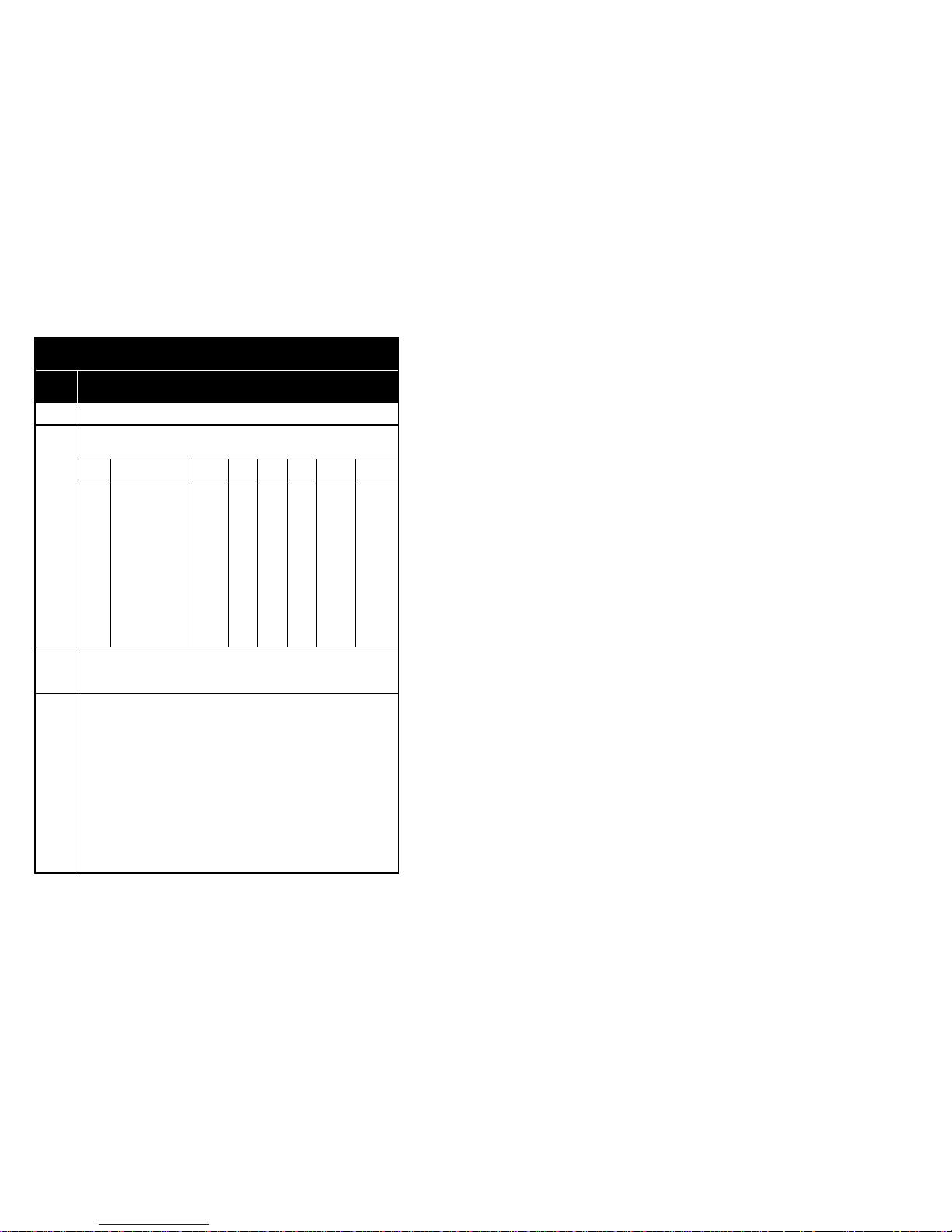
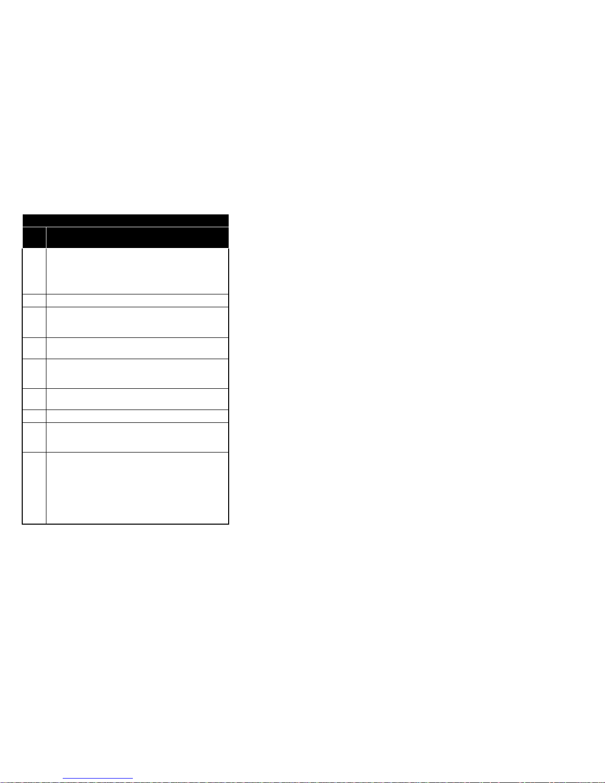
Basic AT Commands
Command
Description
A Answer an Incoming Call
B
Select Communications standard (for low speed
connections)
300
bps
1200 2400 4800 7200 9600 12
Kbps
14.4
B, B0 V.21 V.22 + + + + + +
B1 Bell
103J*
Bell 212A* + + + + + +
B2 + O:V.23R1200/T75
A:V.23T1200/R75
+ + + + + +
B3 + O:V.23 T1200/R75
A:V.23 R1200/T75
+ + + + + +
B15 V. 21 + + + + + + +
B16 Bell
103J
+ + + + + + +
B30 + + V.22bis* + + + + +
B41 + + + V.32* + + + +
B52 + + + + V.32* + + +
B60 + + + + + V.32* + +
B70 + + + + + + V.32bis* +
B75 + + + + + + + V.22bis*
C Carrier control option
C, C0 Transmit carrier is always off (Returns Error)
C1 Modem manages transmit carrier switching*
D Dial a Number
Dial Modifiers:
J Link Negotiation: Sets *H1 for a single connection
K Cellular Connection: Sets )M1 for a single connection
P Pulse dialing
R Originate call in answer mode
S=n Dial stored Telephone Numbers (n=0-3)
T Tone dialing
W Wait for dial tone
, Pause (for time in S8, default 2 seconds)
! Hook Flash
@ Wait for silence /Quiet Answer
; Return to Command Mode after dialing
Page 57
53
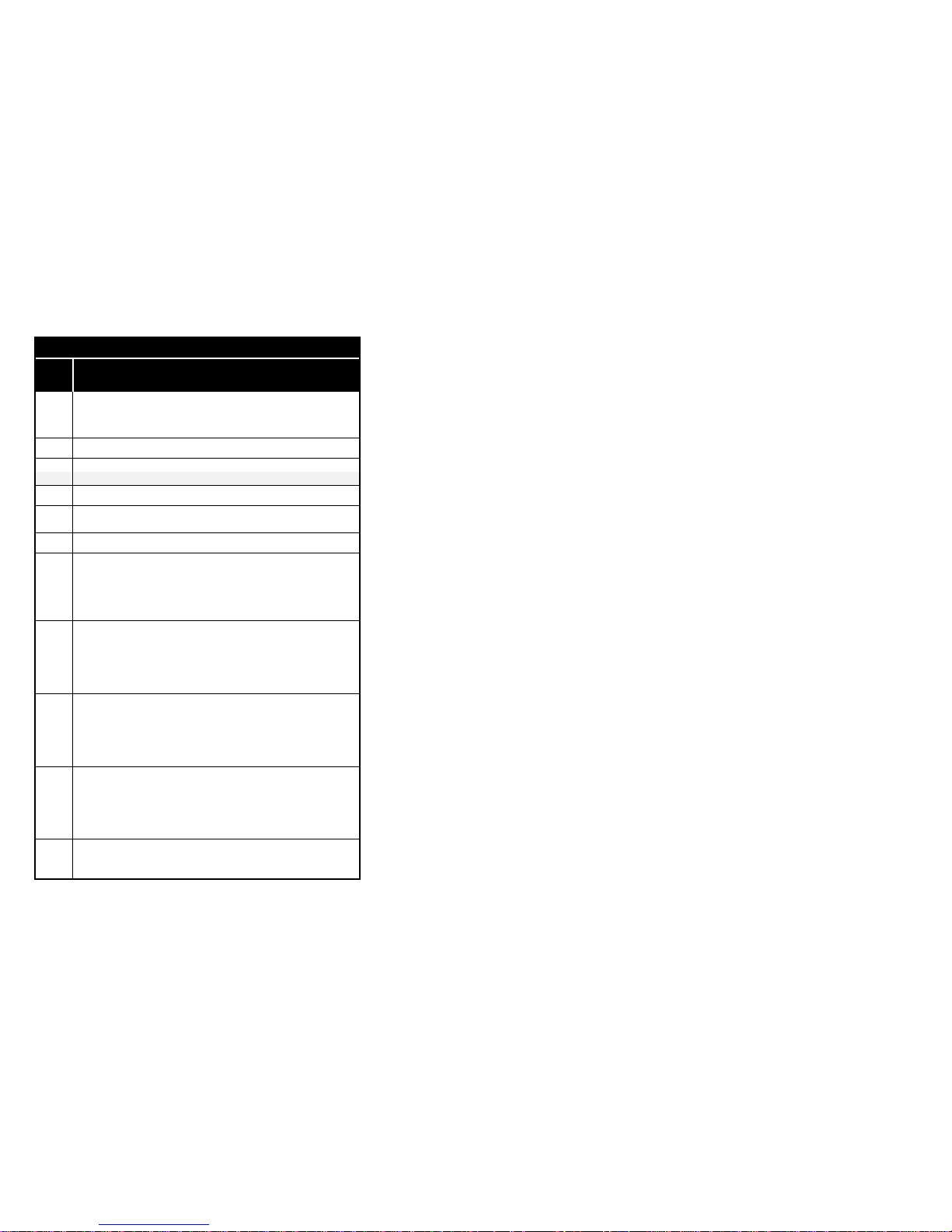
Basic AT Commands
Command
Description
E Offline echo command
E, E0 Echo disabled
E1 Echo enabled *
F Online echo command
F, F0 Echo enabled (Returns Error)
F1 Echo disabled *
H Switch hook control
H, H0 Go on-hook (execute hang up process)
H1 Go off-hook (on-line)
I Identification/checksum option
I, I0 Report product code
I1 Display ROM checksum
I2 Verify ROM checksum
I3 Report ROM components
I4 Modem capabilities (encoded bitmapped string)
L Speaker volume
L, L0 Low
L1 Low
L2 High*
L3 High
M Speaker control
M, M0 Speaker always off
M1 Speaker on until carrier is detected *
M2 Speaker always on
M3 Speaker off during dialing, then on until carrier is detected
N Select negotiate handshake
N0 When originating or answering, handshake only at the communication
standard specified by S37 and Bn
N1 When originating or answering, begin handshake in V8. During
handshake, a speed change may occur (automode)* (default)
N2 When originating or answering, begin handshake at the
communication standard specified by Bn and S37. During handshake,
a speed change may occur (automode no V.8)*
Page 58
54
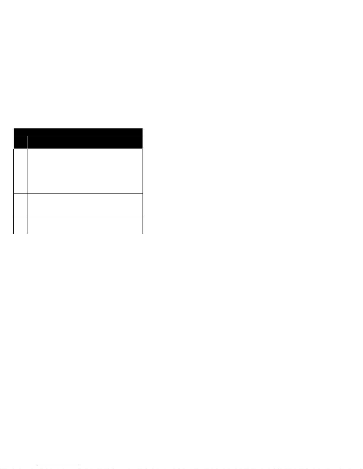
Basic AT Commands
Command
Description
N3 When originating or answering, handshake only in V.8
O Return to On-line state
O,O0 Returns modem to a previously established on-line state
O1 Begins an equalizer retrain sequence, then returns to on-line state
O3 Issues rate renegotiation sequence, then returns to on-line state
P Enable pulse dialing
Q Result code display option
Q, Q0
All Result codes enabled *
Q1 All Result codes disabled
S Select an S register
Sn n=0-112: S register address
Sn=x Write to an S register
n=0-112: S register address
x=0-255: S register value
Sn? Read an S register
n=0-112: S register address
T Enable tone dialing
V Select Result code format
V, V0 Result codes are displayed in Numeric form
V1 Result codes are displayed in text (Verbose) form *
W Select extended result code
W, W0 CONNECT result code reports DTE speed;
If S95=0, then disable all extended result codes *
W1 CONNECT result code reports DTE speed;
If S95=0, then enable the CARRIER and PROTOCOL extended result
codes
W2 CONNECT result code reports DCE speed;
If S95=0, then disable all extended result codes
Page 59
55
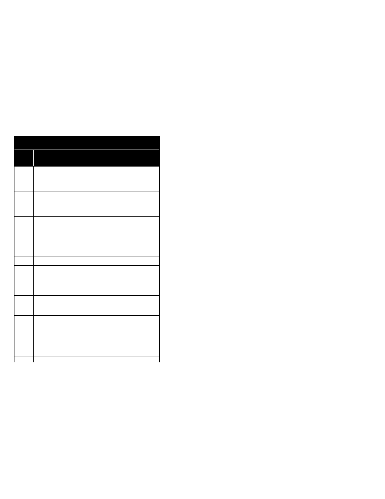
Basic AT Commands
Command
Description
X Result code set/call progress
X, X0
Result codes 0...4 enabled. Busy and dial tone detect disabled (Blind dial)
X1
Result codes 0...5,10 enabled. Busy and dial tone detect disabled
(Blind dial)
X2
Result codes 0...6,10 enabled. Busy detect disabled and dial tone
detect enabled
X3
Result codes 0...5,7,10 enabled. Busy detect enabled and dial tone detect
disabled
X4
Result codes 0...7,10 enabled. Busy and dial tone detect enabled *
Y Select Long space disconnect
Y, Y0 Disable long space disconnect *
Y1 Enable long space disconnect (1.6 seconds of BREAK will terminate the
connect)
Z Recall stored profile
Z, Z0 Recall stored profile 0
Z1 Recall stored profile 1
Page 60
56
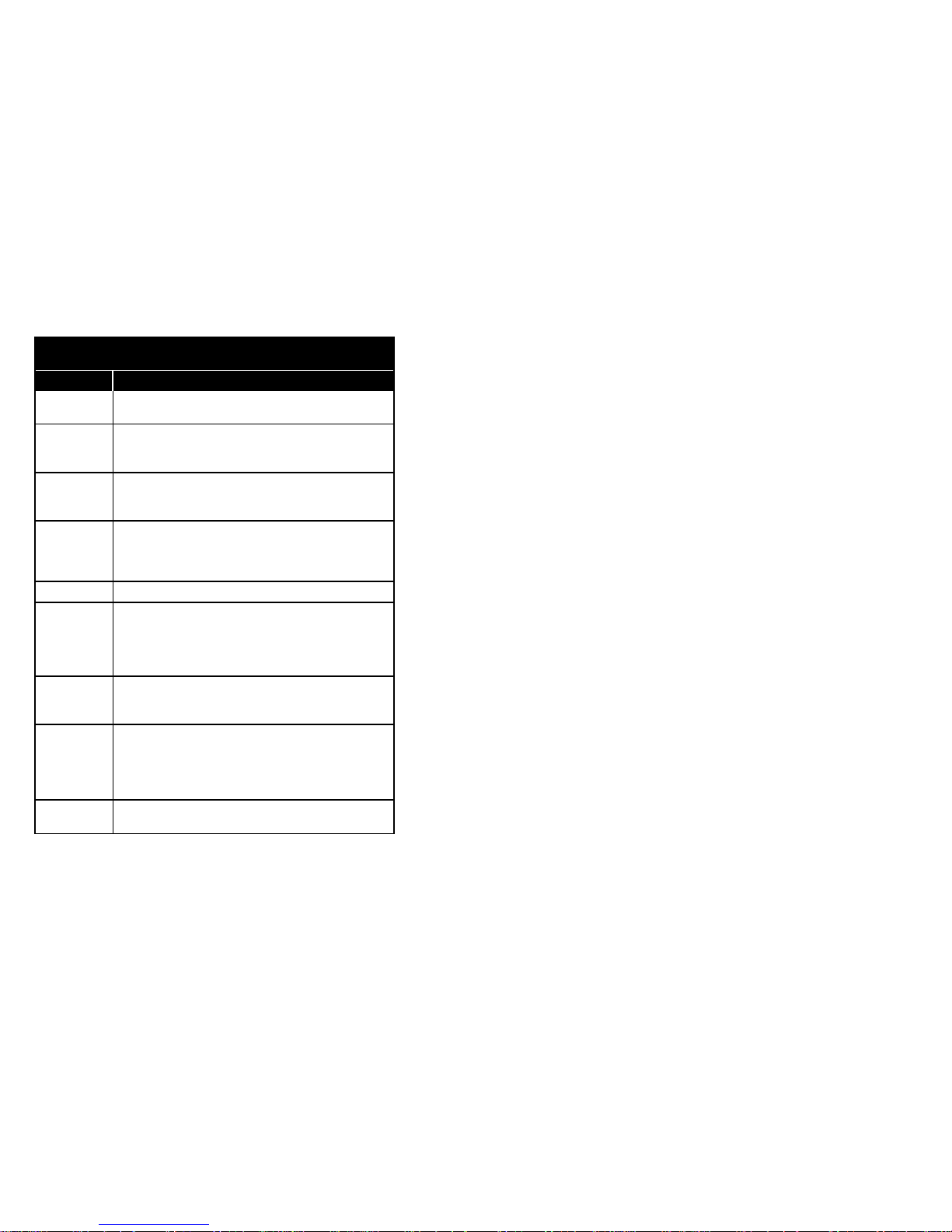
Extended AT "&" Commands
Command
Description
&B Select V.32 auto retrain
&B, &B0 Hangup if bad EQM, do not retrain
&B1
Retrain, if bad EQM. If unable to retrain within time specified in S7, hangup *
&B2 Do not hangup and do not retrain (i.e., tolerate bad line)
&C Select Data Carrier Detect (DCD) Option
&C, &C0 State of carrier from remote modem is ignored. DCD is always ON
&C1 State of carrier from remote modem is tracked. DCD reflects the state of
carrier *
&Dn Select Data Terminal Ready (DTR) Option
&D, &D0 Ignore DTR, behave as if DTR is active all the time
&D1 ON-to-OFF transition: Switch to command mode (if in data mode) and return
OK
&D2 ON-to-OFF transition: Disconnect, return OK, disable autoanswer while DTR
is off *
&D3 ON-to-OFF transition: Perform a soft reset (ATZ) and restore stored profile
&F Load factory defaults
&G
Guard tone option (for V22/V22bis connections in answer
mode)
&G, &G0
Guard tone disabled *
&G1 550Hz guard tone enabled
&G2 1800Hz guard tone enabled
&J Auxiliary relay control
&J, &J0
Auxiliary relay is never operated *
&J1 Reserved
&K Select flow control
&K, &K0 Flow control disabled
&K1 Reserved
&K2 Reserved
&K3
Enable hardware flow control (RTS/CTS) *
&K4
&K5
Enable software flow control (XON/XOFF)
Reserved
&L, &L0
Dial up line processing *
Page 61

57
&L1 Reserved
&M Select communication mode
&M, &M0 Asynchronous Mode *
&M1,&M2
,
&M3
reserved
&P Dial pulse ratio
&P, &P0
Make = 39%, Break = 61% for use in the United States and Canada *
&P1 Make = 33%, Break = 67% for use in the United Kingdom and Hong Kong
&Q Communications mode option
&Q, &Q0 Asynchronous Mode *
&Q1,&Q2
,&Q3
reserved
&R Select RTS/CTS option
&R, &R0
CTS tracks RTS while modem is in on-line state *
&R1 RTS is ignored. CTS remains on while the modem is in on-line state
&S Select Data Set Ready (DSR) option
&S, &S0
DSR signal is always on *
&S1 DSR signal is turned on during handshaking and connection,
and turned off in test and idle mode and when the carrier is lost
&T Self Test Commands (V.22bis only)
&T, &T0 Terminate any test in progress
&T1 Start local analog loopback test
&T3 Start local digital loopback test
&T4 Grant remote digital loopback (RDL) request from remote modem
&T5 Deny remote digital loopback (RDL) request from remote modem
&T6 Start remote digital loopback test
&T7 Start remote digital loopback test with self-test (sends CCITT test V.54
pattern)
&T8 Start local analog loopback test with self-test
&U Disable Trellis Coding
&U, &U0
Enable trellis coding (use V32bis for 9600 bps connections)*
&U1 Disable trellis coding (use V32 for 9600 bps connections)
&V View Active Configuration and Stored Configuration Profile
&V, &V0 Display active profile and stored profile 0
&V1 Display active profile and stored profile 1
Page 62

58
&W Store Active Profile in Memory
&W,&W0 Store current profile in memory location 0
&W1 Store current profile in memory location 1
&X Synch Transmit Clock Source Option
&X, &X0
Default*
&X1,&X2 Reserved
&Y Select Default Configuration Profile on power-Up
&Y, &Y0
Use memory profile 0 after power-up *
&Y1 Use memory profile 0 after power-up
&Zn=x Store Telephone Number x in Directory Entry n
x = 0...9, A , B ,C ,D ,# ,* ,T ,P ,R ,W ,@ ,, ,! ,; max. 36 characters
n=0...3: standard stored numbers
n=4 : user programmed quick dial number
n=5 : last dialed number (system controlled)
n=6 : emergency number (dealer programmable only)
Page 63
59
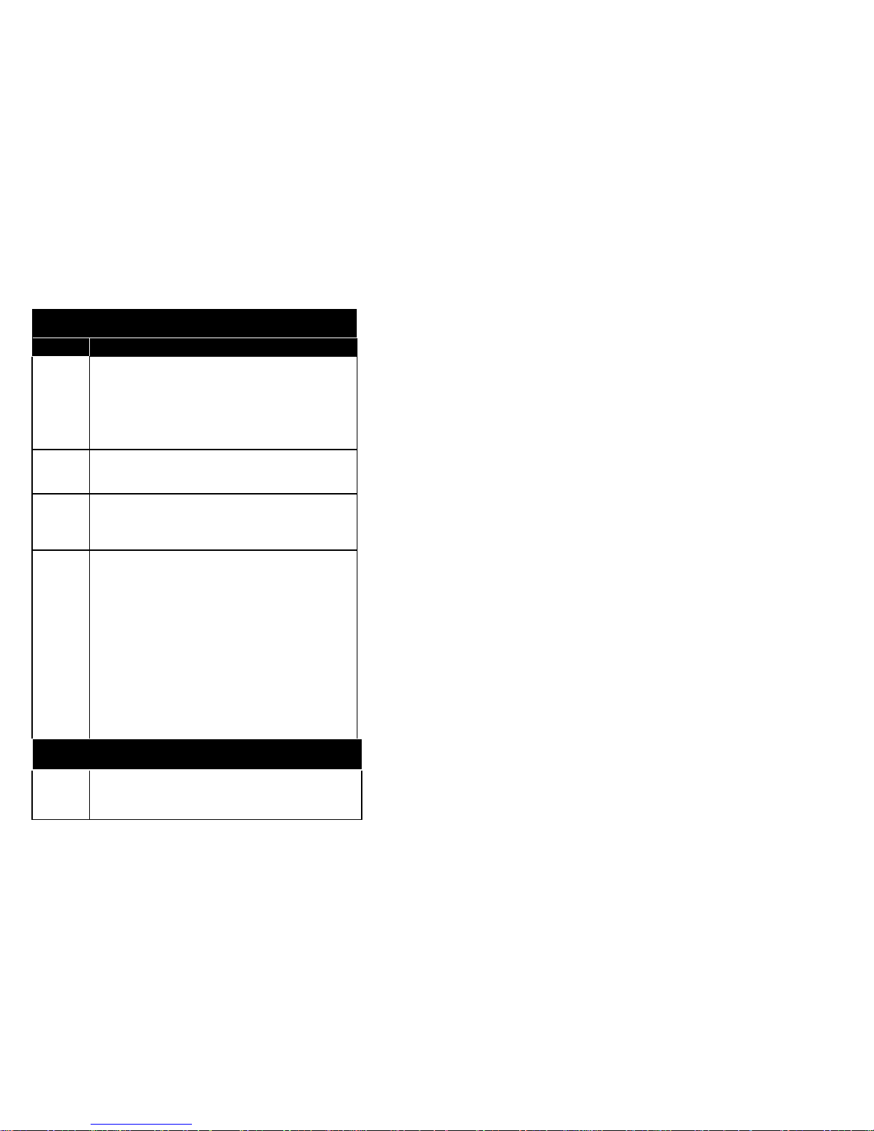
AT Commands for V42/MNP control
Command Description
%A Set Autoreliable Fallback Character
%An n=0...127 (ASCII character) Default: 13
%C Select Data compression Mode
%C, %C0 No compression
%C1
MNP Class 5 compression enabled*
%E Select Auto-retrain (V.22bis and V.32 only)
%E, %E0 Disabled
%E1
Enabled *
%G Auto fallforward/fallback enable (V.22bis and V.32
only)
%G, %G0 Disabled
%G1 Enabled *
%L Read current receive signal level (in - dBm)
%Q Read current Datapump Receive Eye Quality Monitor
EQM value
value: 0...127.
A smaller value indicates a better line condition, this means, that
there is a smaller chance for the receiver to make an data error
%T 400Hz detection
%T, %T0 Enabled
%T1
Disabled *
\A Maximum MNP block size
\A,\A0 Max. 64 characters
\A1 Max. 128 characters
\A2 Max. 192 characters
\A3
Max. 256 characters *
\B Transmit break
\Bn n=0...9: Break length in 100 msec
Page 64

60
Page 65
61
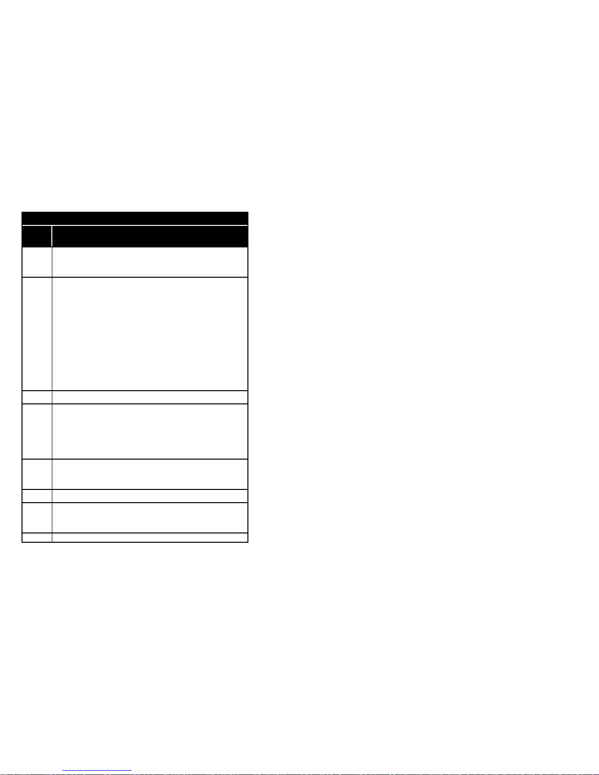
AT Commands for V42/MNP control
Command Description
\C Set autoreliable buffer
\C, \C0
Does not buffer data *
\C1 Buffers data for 4 seconds, until 200 characters have been buffered or
SYN character is detected, then switches to reliable mode. If buffer
fills, data is passed to serial port
\C2 Does not buffer data. Switches to normal mode upon receipt of
autoreliable character and passes it to serial port
\G Set modem port flow control
\G, \G0
Disable port flow control *
\G1 Set port flow control to XON/XOFF
\J DTE Port Bps rate adjust
\J, \J0 Turn off feature (Serial port speed is independent of line connection
speed) *
\J1 Turn on feature (Serial port speed adjusts to line connection speed)
\K Set break control
(In connect state, if reliable mode then transmit break to remote)
\K0, \K2, \K4 Enter command state but do not send a break
\K1 Destructive/Expedited
\K3 Non-destructive/Expedited
\K5 Non-destructive/Non-expedited
(In command state, if reliable mode then transmit break to remote)
\K0, \K1 Destructive/Expedited
\K2, \K3 Non-destructive/Expedited
\K4, \K5 Non-destructive/Non-expedited
(In connect state, if direct mode then receive break at serial port)
\K0, \K2, \K4 Immediately send break and enter command state
\K1, \K3, \K5 Immediately send break through
(In connect state, receive break at modem port, send to serial port)
Modem S-Registers
Reg.
Range
Default Description
\K0, \K1 Destructive/Expedited
\K2, \K3 Non-destructive/Expedited
\K4, \K5 Non-destructive/Non-expedited
Default: 5
Page 66

62
Page 67
63
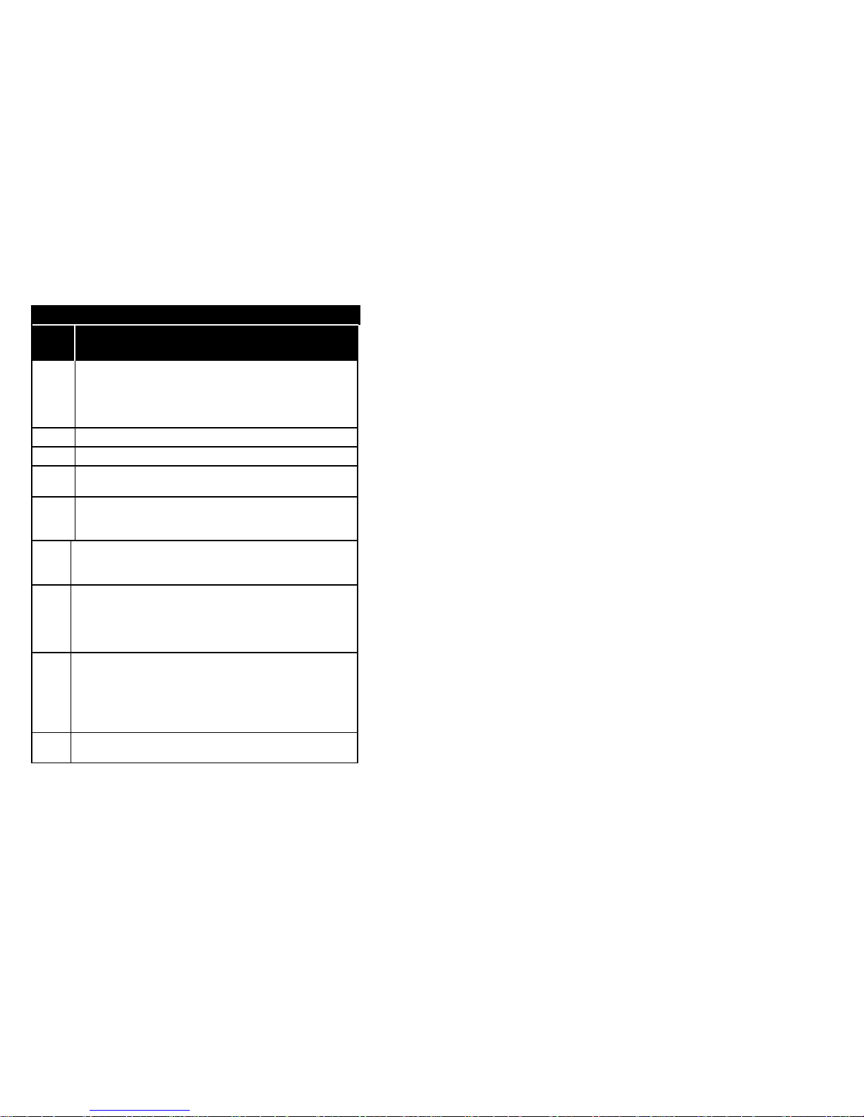
AT Commands for V42/MNP control
CommandDescription
\L Select MNP link Type
\L, \L0
MNP connections will use stream link *
\L1 Reserved
\N Set operating mode
\N, \N0 NORMAL mode: Data buffered, flow control, no
protocols/compression
\N1 DIRECT mode: Data not buffered, no flow control,no
protocols/compression
\N2 MNP reliable mode: Data buffered, flow control, use MNP protocols
only
\N3 V.42 autoreliable mode:Data buffered, flow control, use LAP-M (preferred) or
MNP
\N4 V.42 reliable mode: Data buffered, flow control, use LAP-M protocols
only
\N5 LAP-M reliable mode: Data buffered, flow control, use LAP-M protocols
or normal (default)
\O Originate MNP reliable Connection
\Q Set Serial Port Flow Control
\Q, \Q0 Disables DTE flow control
\Q1 Bidirectional XON/XOFF flow control
\Q2 Unidirectional hardware flow control (modem uses CTS to control transfer
from DTE)
\Q3
Bidirectional hardware flow control (RTS/CTS) *
\T Set Inactivity Timer
\Tn n=0...90: Length in minutes to break connection, if no data transfer occurs
Default: 0 minutes (disabled)
\U Accept MNP autoreliable link
\V Modify result code form
\V, \V0
Enable codes defined by ATV command *
\V1 Enable modified MNP codes (add /REL for reliable connections)
\V1 Enable modified MNP codes (add /REL for reliable connections)
Page 68
64
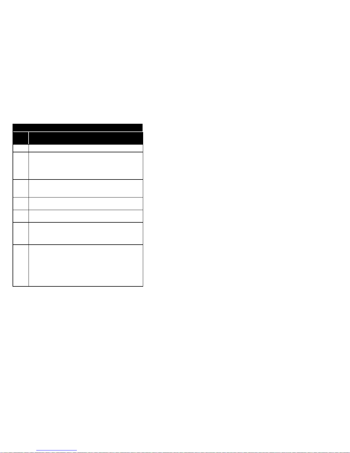
AT Commands for V42/MNP control
Com-
mand
Description
\X Set XON/XOFF pass-through Flow Control
\X, \X0 Processes flow control characters (XON/XOFF) and do not pass to remote
modem *
\X1 Processes flow control characters and passes them through to the local or
remote so they can process the characters
\Y Switch to MNP Reliable mode
\Z Switch to Normal mode
-B Forces a downshift to the next lower speed during an
MNP 10 connection
-C Calling tone option
-C, -C0
Calling tone disabled *
-C1 Calling tone enabled
-J Select V.42 Error Control Detection phase
-J, -J0 Disables the V.42 detect phase
-J1
Enables the V.42 detect phase *
-K Select MNP 10 extended services
-K, -K0 Disables MNP 10 extended services
-K1
Enables MNP extended services *
-K2 Enables MNP extended services without MNP indication during the answer
detect phase
-Qn: Fallback modulation speeds (MNP 10)
-Q, -Q0 Disables fallback from V.32bis or V.32 connection to a 2400 or 1200 bps
connection
-Q1 Enables fallback from V.32bis or V.32 connection to a 2400 bps connection
-Q2 Enables fallback from V.32bis or V.32 connection to a 2400 or 1200 bps
connection *
-U Forces an upshift the the next higher speed during an
MNP 10 connection
Page 69
65
AT Commands for V42/MNP control
Com-
mand
Description
-V Display modem firmware version number
"H V.42bis compression control
"H0 Disable V.42bis
"H1 Enable V.42bis only when transmitting data
"H2 Enable V.42bis only when receiving data
"H3
Enable V.42bis for both transmitting and receiving data *
"M MNP 10 control
"M, "M0 Disable MNP 10
"M1
Enable MNP 10 *
"N V.42bis dictionary size
"Nn n=512...2048: Number of nodes in the V.42bis dictionary
“O V.42bis string length
"On n=6...250: Number of characters (Default: 32)
*H MNP Link negotiation speed
*H, *H0 Link negotiation occurs at the highest supported speed*
*H1 Link negotiation occurs at 1200 bps
*H2 Link negotiation occurs at 4800 bps
)M Power level adjustment and spectral enhancements for cellular
connections
)M, )M0 Auto-adjust power level (only) if the remote is )M1.
Use for modems that will connect to both cellular and non-cellular site
modems. (PSTN / Mode 0 default)
)M1 Auto-adjust power level and perform spectral enhancements.
For cellular site modems this forces adjustment of power level and spectral
enhancements. (AMPS/Mode 1 default)
Page 70
66
Result Codes
Numeric
Code
Verbose Code
0 OK
1 CONNECT
2 RING
3 NO CARRIER
4 ERROR
5 CONNECT 1200
6 NO DIALTONE
7 BUSY
8 NO ANSWER
9 CONNECT 600
10 CONNECT 2400
11 CONNECT 4800
12 CONNECT 9600
13 CONNECT 14400
14 CONNECT 19200
18 CONNECT 57600
24 CONNECT 7200
25 CONNECT 12000
26 CONNECT 1200/75
27 CONNECT 75/1200
28 CONNECT 38400
31 CONNECT 115200
40 CARRIER 300
42 CARRIER 75/1200
43 CARRIER 1200/75
46 CARRIER 1200
47 CARRIER 2400
48 CARRIER 4800
49 CARRIER 7200
50 CARRIER 9600
51 CARRIER 12000
52 CARRIER 14400
65 RINGBACK
66 COMPRESSION: MNP5
67 COMPRESSION: V.42BIS
69 COMPRESSION: NONE
Page 71

67
Result Codes
Numeric
Code
Verbose Code
70 PROTOCOL: NONE
77 PROTOCOL: LAPM
80 PROTOCOL: MNP
81 PROTOCOL: MNP 2
82 PROTOCOL: MNP 3
83 PROTOCOL: MNP 2, 4
84 PROTOCOL: MNP 3, 4
85 PROTOCOL: MNP 2, 10
86 PROTOCOL: MNP 3, 10
87 PROTOCOL: MNP 2, 4, 10
88 PROTOCOL: MNP 3, 4, 10
89 PROTOCOL: MNP 2,10 (CELLULAR)
90 PROTOCOL: MNP 3,10 (CELLULAR)
91 PROTOCOL: MNP 2,10 (EC)
92 PROTOCOL: MNP 3,10 (EC)
93 PROTOCOL: MNP 2,4,10 (CELLULAR)
94 PROTOCOL: MNP 3,4,10 (CELLULAR)
95 PROTOCOL: MNP 2,4,10 (EC)
96 PROTOCOL: MNP 3,4,10 (EC)
Page 72
68
Modem S-Registers
Reg. Range Default Description
S0 0-255 0 Ring to auto-answer on
S1 0-255 0 Ring count
S2 0-255 43 Escape Character (decimal ASCII value)
S3 0-127 13 Carriage Return character (decimal ASCII value)
S4 0-127 10 Line Feed Character (decimal ASCII value)
S5 0-127 8 Backspace Character (decimal ASCII value)
S6 2-255 2 Pause before blind dialing in seconds
S7 1-255 90 Wait time for carrier after dialing in seconds
S8 0-255 2 Pause time for command or dial modifier (comma)
S9 1-255 6 Carrier recovery time (1/10 seconds)
S10 1-255 14 Lost carrier hang up delay (1/10 seconds)
S11 50-255 95 DTMF dialing speed (Duration and spacing in
milliseconds)
S12 0-255 50 Escape Sequence Guard time (1/50 seconds)
S13 Reserved
S14 0-255 Bit mapped options:
Bit 0 Reserved
Bit 1 0 E0 is selected
1 E1 is selected *
Bit 6, 2 0 Q0 is selected *
1 Q1 is selected
Bit 3 0 V0 is selected
1 V1 is selected *
Bit 4 0 Dumb mode off *
1 Dumb mode on
Bit 5 0 T is selected *
1 P is selected
Bit 7 0 Answer
1 Originate *
Page 73
69
Modem S-Registers
Reg. Range Default Description
S15 Reserved
S16 0-255 0 Modem test options (bitmapped):
Bit 0 0 Local analog loopback
disabled *
1 Local analog loopback
enabled (&T1)
Bit 1 0 Reserved
Bit 2 0 Local digital loopback
disabled *
1 Local digital loopback
enabled (&T3)
Bit 3 0 Remote digital loopback off *
1 Remote digital loopback in
progress (&T6)
Bit 4 0 RDL not active *
1 RDL request from distant end
is in service
Bit 5 0 Remote digital loopback with
self-test disabled *
1 Remote digital loopback with
self-test enabled (&T7)
Bit 6 0 Analog loopback with self-
test disabled *
1 Analog loopback with self-
test enabled (&T8)
Bit 7 0 Reserved
Page 74
70
Modem S-Registers
Reg. Range Default Description
S17 Reserved
S18 0-255 0 Modem test timer (seconds)
S19S20
Reserved
S21 Bit mapped options
Bit 0 0 &J0 is selected *
1 &J1 is selected
Bit 1 0 Reserved
Bit 2 0 &R0 is selected *
1 &R1 is selected
Bit 4, 3 00 &D0 is selected
01 &D1 is selected
10 &D2 is selected *
11 &D3 is selected
Bit 5 0 &C0 is selected
1 &C1 is selected *
Bit 6 0 &S0 is selected *
1 &S1 is selected
Bit 7 0 Y0 is selected *
1 Y1 is selected
S22 Bit mapped options
Bit 1, 0 00 Reserved
01 L1 is selected
10 L2 is selected *
11 L3 is selected
Bit 3, 2 00 M0 is selected
01 M1 is selected *
10 M2 is selected
11 M3 is selected
Bit 6, 5, 4 000 X0 is selected
001 Reserved
010 Reserved
011 Reserved
100 X1 is selected
101 X2 is selected
110 X3 is selected
111 X4 is selected *
Bit 7 0 &P0 is selected *
1 &P1 is selected
Page 75
71
Modem S-Registers
Reg.
Range
Default Description
S23 Bit mapped options
Bit 0 0 &T5 is selected
1 &T4 is selected *
Bit 3,2,1 000 0-300 bps rate
001 1200 bps
010 2400 bps
011 4800 bps
100 7200 bps
101 9600 bps
110 19.2K bps
111 38.4K bps *
Bit 5, 4 00 Even parity *
01 Space parity/no parity
10 Odd parity
11 Mark
Bit 7, 6 00 &G0 is selected *
01 &G1 is selected
10 &G2 is selected
11 Reserved
S24 Reserved
S25 Detect DTR change
0-255 5 (100ths second) if on line or on-line command state
0-255 5 (1 second) otherwise
S26 RTS to CTS delay interval
0-255 1 0 - 255 (100ths second)
Page 76
72
Modem S-Registers
Reg.
Range
DefaultDescription
S27 Bit mapped options
Bit 3,1, 0 000 &Q0 is selected *
001 &Q1 is selected
010 &Q2 is selected
011 &Q3 is selected
100 &Q4 is selected
101 Not used
110 Not used
111 Not used
Bit 2 0 &L0 is selected *
1 &L1 is selected
Bit 5, 4 00 &X0 is selected *
01 &X1 is selected
10 &X2 is selected
11 Reserved
Bit 6 0 B0 is selected
1 B1 is selected *
Bit 7 Reserved
S28-9 Reserved
S30 0-90 0 Modem Inactivity timer value (minutes)
S31-6 Reserved
S37 0-11 0 Desired DCE speed
(only, when not in automode, ATN0)
0 Attempt to connect@last AT speed
1 Reserved
2 Reserved
3 Attempt a 300 bps connection
4 Reserved
5 Attempt a 1200 bps connection
6 Attempt a 2400 bps connection
7 Attempt a 4800 bps connection
8 Attempt a 7200 bps connection
9 Attempt a 9600 bps connection
10 Attempt a 12.0K bps connection
11 Attempt a 14.4K bps connection
S38 3-255 30 Non-MNP10 Fall Forward Time (seconds)
Page 77
73
Modem S-Registers
Reg.
Range
Default Description
S39 0-3 Cellular Modem Filter Override
0 No override (use Rockwell EC filter when
mobile,
use Rockwell PSTN filter when land-line to
mobile,
use no filters for land-line to land-line links.
1 Always use TX-CELL filter
2 Always use Rockwell EC filter
3 Always use Rockwell PSTN filter
S40S90
Reserved
S91 9-31 9 Select Data Line transmit level (-dBm)
S92S94
Reserved
S95 0-255 0 Extended result code bit map
Bit 0 Verbose CONNECT result code indicates
the DCE speed (rather than the DTE
speed)
Bit 1 Append "/ARQ" to the verbose CONNECT
result code if the protocol is not "NONE"
Bit 2 Enable the CARRIER result codes
Bit 3 Enable the PROTOCOL result codes
Bit 4 Reserved
Bit 5 Enable COMPRESSION result codes
Bit 6 Enable PROTOCOL result codes 81-83 for
MNP connections (in place of result code
80)
S108 0-3 1 Signal quality selector
0 No limit
1 Low quality
2 Medium quality
3 High quality
Page 78
74
Modem S-Registers
Reg. Range Default Description
S109 0-255 62 V.32bis carrier speed selector
1 Reserved
2 4800 bps
4 7200 bps
8 9600 bps
16 12.0K bps
32 14.4K bps
64 Reserved
128 Reserved
Note: The values may be added to specify several speeds.
When viewed as an 8-bit number, the register is bit mapped.
S110 0-2 2 V.32/V.32bis selector
0 V.32 enabled
1 V.32bis enabled
2 V.32bis and automatic rate re-negotiation
enabled
S112 0-14 0 DTE speed select during data transfer
0 Last AT speed
1 Reserved
2 300 bps
3 1200 bps
4 2400 bps
5 4800 bps
6 7200 bps
7 9600 bps
8 12000 bps
9 14400 bps
10 16800 bps
11 19200 bps
12 38400 bps
13 57600 bps
14 600 bps
Page 79
75
Fax Class 1 AT Commands
Command Description
+FTS
Stop transmission and wait
+FRS
Receive silence
+FTM
Facsimilie transmit
+FRM
Facsimilie receive
+FTH
HDLC transmit
+FRH
HDLC receive
Please refer to EIA/TIA 578 for specific details on Fax Class 1 command operation.
Fax Class 2 AT Commands
Command Description
+FAXERR
Fax error value
+FBADLIN
Number of consecutive bad lines for a bad page
+FBADMUL
Multiplier to determine error rate threshold
+FBOR
Phase C data bit order
+FBUF
Buffer size (read only)
+FBUG
Session message reporting enable
+FCQ
Copy Quality
+FCR
Capability to receive
+FCTCRTY
CTC retry value
+FDCC
Establish DCE capabilities
+FDCS
Current session parameters (read only)
+FDFFC
Data compression format conversion
+FDIS
Current session negotiation position
+FDR
Begin or continue phase C data reception
+FDT
Begin or continue sending
+FECM
Error correction mode control
+FET
End the page or document
+FK
Kill operation, orderly fax abort
+FLID
Local fax station ID string, TSI or CSI
+FLNFC
Page length format conversion
+FLPL
Indicate document available for polling
+FMDL
Identify DCE
+FMFR
Identify DCE manufacturer
+FMINSP
Minimum phase C speed
+FPHCTO
Phase C time out
+FPTS
Page transfer status
+FREV
Identify DCE revision
Page 80
76
+FRBC
Phase C data receive byte count
+FREL
Phase C received EOL alignment
+FSPL
Enable polling
+FTBC
Phase C data transmit byte count
+FVRFC
Vertical resolution format conversion
+FWDFC
Page width format conversion
Please refer to EIA Tn 2388 for specific details on FAX Class 2 command operation.
Page 81
77
Fax Class 2.0 AT Commands
Command Description
+FBS:
Buffer size (read only)
+FBO:
Phase C data bit order
+FBU:
HDLC frame reporting parameter
+FCC:
DCE capabilities parameters
+FCQ:
Copy quality checking parameter
+FCR:
Capability to receive parameter
+FCS:
Current session results parameter
+FCT:
DTE phase C time out parameter
+FDR:
Data reception command
+FDT:
Data transmission command
+FEA:
Phase C received EOL alignment parameter
+FFC:
Format conversion parameter
+FHS:
Call termination status parameter
+FIE:
Procedure interrupt enable parameter
+FIS:
Current session parameters
+FKS:
Session terminate command
+FLI:
Local ID string parameter, TSI or CSI
+FLP:
Indicate document to poll parameter
+FMI:
Request DCE manufacturer
+FMM:
Request DCE model
+FMR:
Request DCE revision
+FMS:
Mimimum phase C speed parameter
+FNR:
Negotiation message reporting control parameter
+FNS:
Non-standard frame FIF parameter
+FPI:
Local polling ID string parameter
+FPS:
Page status parameter
+FRQ:
Receive quality thresholds parameter
+FRY:
ECM retry value parameter
+FSP:
Request to poll parameter
Please refer to EIA/TIA 592 for specific details on Fax Class 2.0 command operation.
Page 82
78
Rockwell Voice Mode AT Commands
AT Command Set Extensions Global to any Mode
Command Description
#BDR
Select Baud Rate
#CLS
Select data, fax, or voice
#MDL
Identify Model
#MFR
Identify Manufacturer
#REV
Identify Revision Level
Page 83
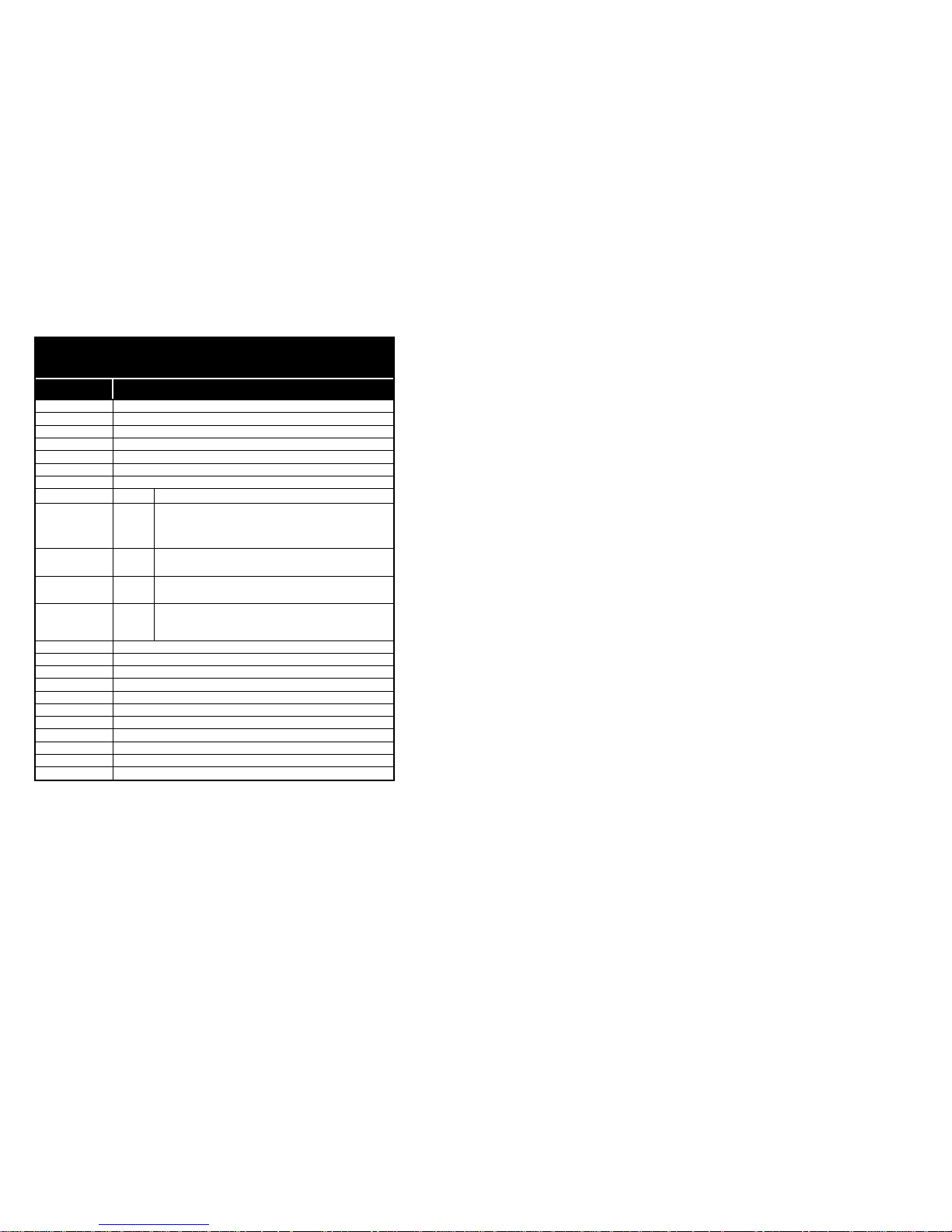
79
Rockwell Voice Mode AT Commands
AT Command Enabled Only in Voice Mode (#CLS=8)
Command Description
#VBS
Bits Per Sample
#VBT
Beep Tone Timer
#VBQ?
Query Buffer Size
#VCI?
Identify Compression Method
#VGR
Receive Gain Selection
#VGT
Transmit Gain Selection
#VLS
Voice Line Select
n
Device Type and Considerations
0
Telephone Line: This is the default device selected. In this configuration, the modem
can alternately record from or playback to the telephone line. The modem currently
supports one telephone line, which is in the first position of the #VLS =? response.
If a telephone line is selected (unless already selected), the modem must be onhook or it hangs up. The OK message is generated.
2
Transmit Only Device: This is the Jabra speaker. When this device is selected, the
modem immediately enters Online Voice Command Mode, and the VCON response
is sent.
3
Receive Only Device: This is the Jabra microphone. When this device is selected,
the modem immediately enters Online Voice Command Mode, and the VCON
response is sent.
4
Telephone line with Speaker ON: This device type can be used to allow the DTE to
select the telephone line (if present) with the modem PCMCIA speaker also turned
ON. This can be used by the DTE to allow the user to monitor an incoming message
as it is recorded.
#VRA
Ringback Goes Away Timer (Originate)
#VRN
Ringback Never Came Timer (Originate)
#VRX
Voice Reveive
#VSD
Silence Detection
#VSK
Buffer “Skid” Setting
#VSP
Silence Detection Period (Voice Receive)
#VSR
Sampling Rate Selection
#VSS
Silence Sensitivity Tuner (Voice Receive)
#VTD
Tone Reporting Capabilities
#VTS
Play Tone String In Online Voice Command Mode
#VTX
Voice Transmit
Please refer to the Rockwell Document No. 883 (Chapter 7) for specific
details on Rockwell voice commands.
Page 84
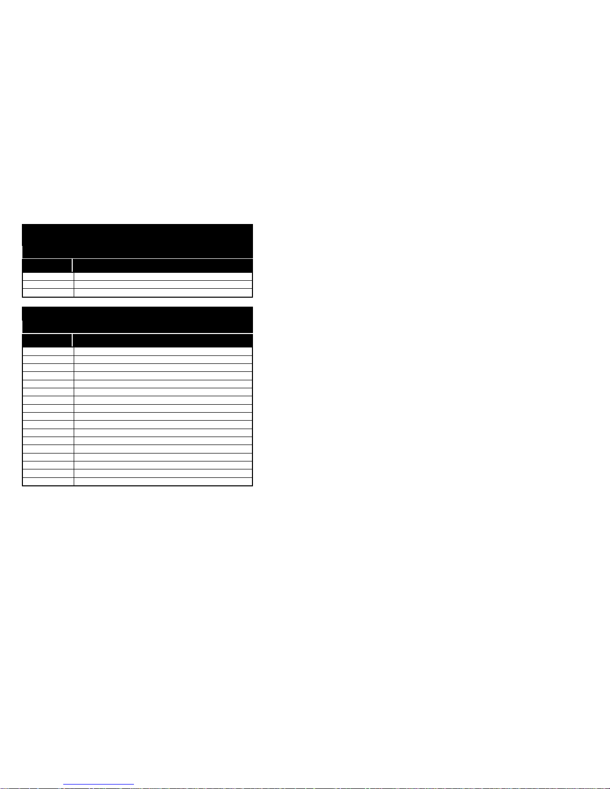
80
IS-101 Voice Mode AT Commands
AT Command Set Extensions Global to any Mode
Command Description
+FMI?
Manufacturer Identification
+FMM?
Product Identification
+FMR?
Revision Identification
IS-101 Voice Mode AT Commands
AT Command Enabled Only in Voice Mode (+FCLASS=8)
Command Description
+VIP
Initialize Voice Parameters
+VRX
Voice Receive
+VTS
Play Tone String
+VTX
Voice Transmit
+VGR
Receive Gain Selection
+VGT
Transmit Gain Selection
+VIT
Voice Inactivity Timer
+VLS
Voice Line Select
+VRA
Ringback Goes Away Timer (Originate)
+VRN
Ringback Never Came Timer (Originate)
+VSD
Silence Detection
+VTD
Beep Tone Duration TImer
+VDR
Distinctive Ring Reporting
+VDT
Control Tone Cadence Reporting
+VEM
Event Reporting And Masking
+VBT
Buffer Threshold Setting
+VPR
Select Baud Rate
Please refer to IS-101 for specific details on voice command operation.
Page 85
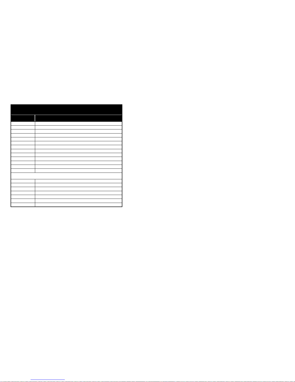
81
Voice View AT Commands
Command Description
+FCLASS=80 New Service Class 80 specifies VoiceView.
-SVV Start VoiceView data mode
-SAC Accept data mode request
-SIP Initialize VoiceView parameters
-SIC Reset capabilities data to default setting
-SSQ Start capabilities query
-SDA Start modem data mode
-SFX Start facsimile data mode
-SQR Capabilities query response control
-SCD Set capabilities data
-SER? VoiceView error reporting
-SSP Set VoiceView transmission speeds
-SSR Start sequence response control
VoiceView Event Summary
-SSV VoiceView data mode request received
-SMD Modem data mode request received
-SFA Facsimile data mode request received
-SRA ADSI CAS response to capabilities query
-SQR Capabilities query message
-SRC Capabilities response message
-STO Talkoff event message
For more information on VoiceView commands refer to the Radish documentation.
Page 86
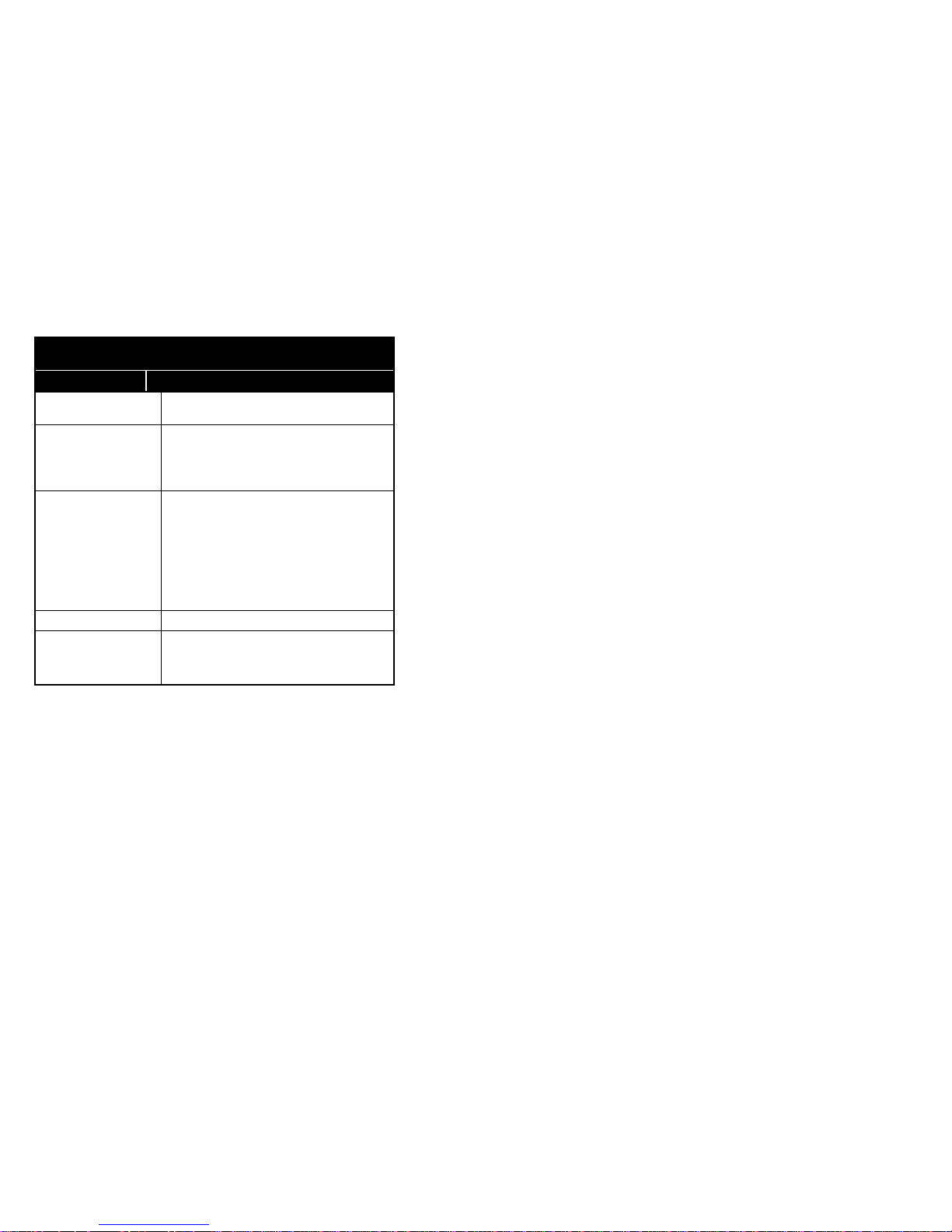
82
Phonebook AT Commands
Command Description
+CPBR=n1[,n2] Reads index n1 (through n2) with number
and text fields
+CPBW=
n1[,<num>,<text>]
Deletes Phonebook entry n1
(Writes entry n1 with specified number and text fields)
n1=255 initializes the phonebook
+CPBF=<string> Returns entries whose text fields begin with
<string>
+CPBI=F(L,N,P,E)? Returns specified Adress book index:
F: alphabetically first entry
L: alphabetically last entry
N: alphabetically next entry to current entry
P: alphabetically prior entry to current entry
E: next available empty entry
+CMEE=n Extended Address Book error messages
n=0: Disabled (default)
n=1: Enabled
"+CME ERROR: <err>" result codes for phonebook
commands
Page 87
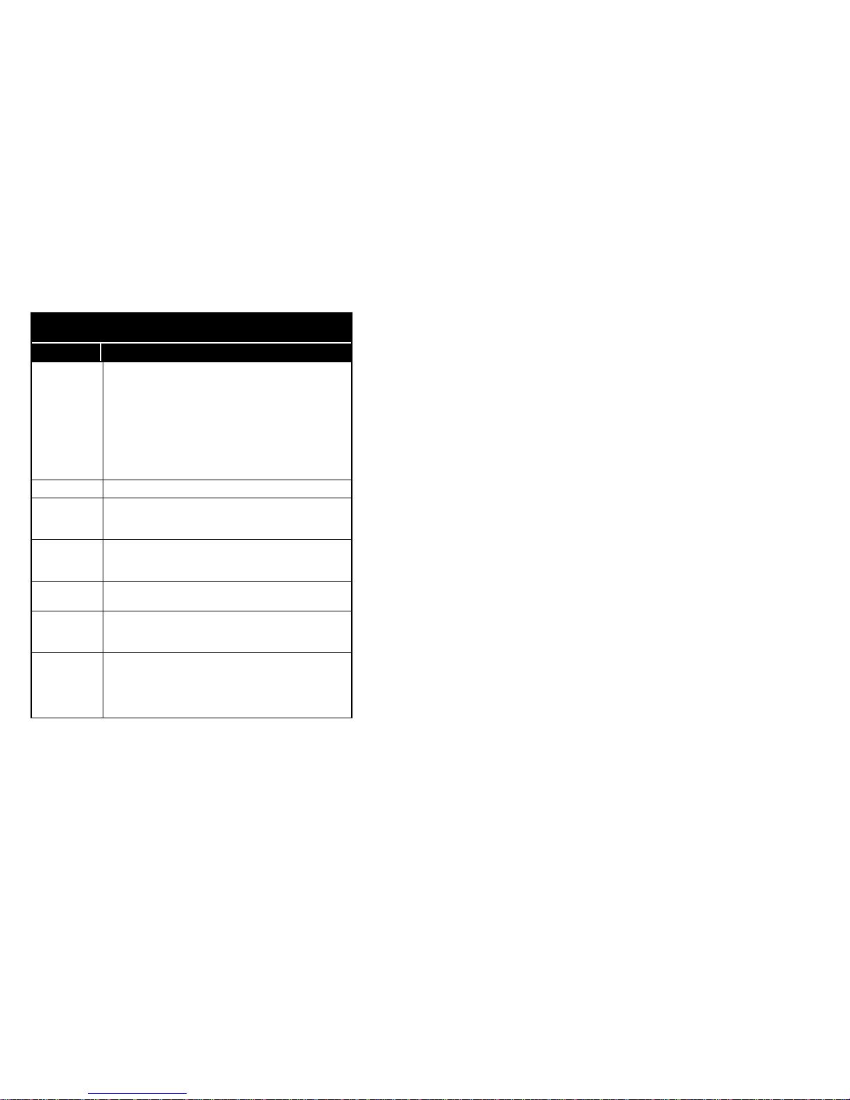
83
Wireless (AMPS) Mode AT Commands
Command Description
+WS46=
Wireless (AMPS) /Wireline (PSTN) Data Service
Selection
(see also !MODE)
0: Wireline (PSTN) Phone
1: Wireline (PSTN) Modem
7: Wireless (AMPS) Modem
17: Wireless (AMPS) Phone
Note: Default value depends on attached accessory (DAA,
Earphone)
+WCXF Display Supported PCCA Annex F commands
+WS50? Normalized Signal Strength (RSSI, 0...100%)
0: -120 dBm
100: -40 dBm
+WS51= Carrier Detect Signal Strength Threshold:
0...100: Threshold value (relative RSSI in %, see +WS50)
255: disabled (default)
+WS52? Battery / PCMCIA voltage level
0...100: (100 = 9 volts)
+WS56? Registration Status
0: no service available
1: service available and registerd with cell site
+WS58= Idle Time-out Value (see also !SLEEP=)
0: Immediate
1...60: Time in seconds
61...120: Time in minutes
255: disabled (default)
Page 88
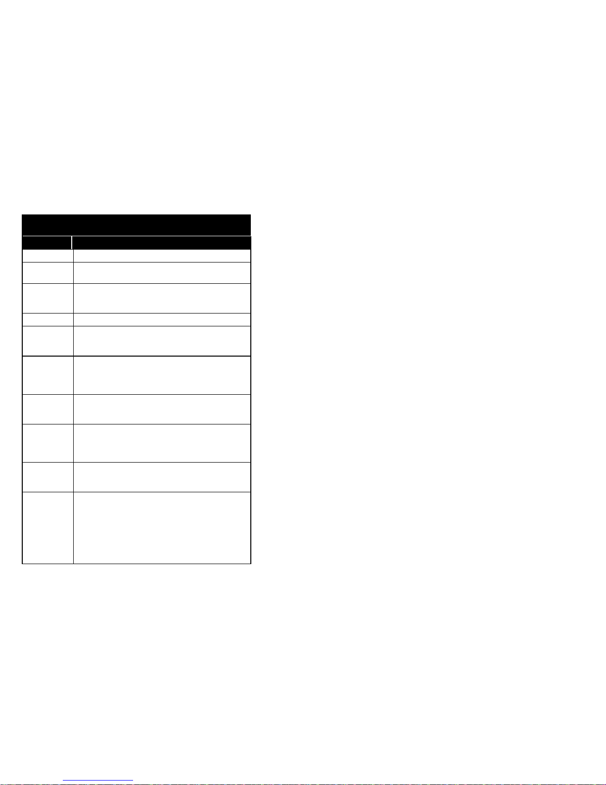
84
Wireless (AMPS) Mode AT Commands
Command Description
+WCID? Display System ID
+WCPN= Personal Identification Number
“newPIN”,“old”PIN”
+WCLK= DCE Lock/Unlock
0: Unlock
1: Lock
+WDAC Display Supported PCCA Annex I commands
+WSTL= Call Session Time Limit
0: Disable (default)
1-255: Time in 10 second units
+WECR= Enable Cellular Result Codes
0: PSTN results (default)
1: Cellular results
5: Extended Cellular results
+WRLK= Roam Lockout
0: No Lockout (default)
1: Lockout
+WBAG= Bias Modem Audio Gain
0: Default level
1-15: Increase level
(-1)- (-15): Decrease level
+WPTH= Audio Call Path
0: Handset
1: Modem
!MODE=
Wireless (AMPS) / Wireline (PSTN) Data Service
Selection
0: Wireline (PSTN) modem
1: Wireless (AMPS) modem
2: Wireline (PSTN) phone
3: Wireless (AMPS) phone
Note: Default value depends on attached accessory (DAA,
Earphone)
Page 89
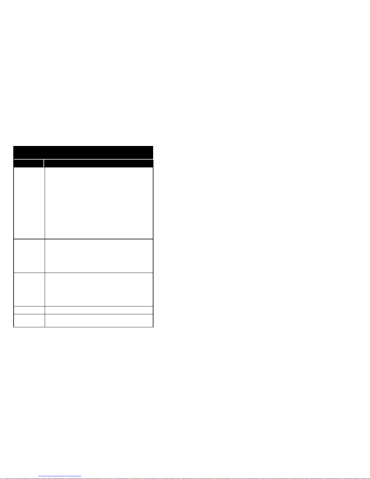
85
Wireless (AMPS) Mode AT Commands
Command Description
!WCFG=
n1,n2,n3
Wireless configurations
n1 - System Select:
0: System A Only
1: System B Only
2: System A Prefered
3: System B Prefered
n2 - Local phone number selection (NAM) (operation and
programming)
1-2: Stored number (1-2)
n3 - Discontinuous transmission (DTX):
0: Disabled (default)
1: Enabled
!WRX= Set Audio receive level
0: Default volume
1-15: Increase in dB
(-1)-(-15): Decrease in dB
^: Increment by one dB step
v: Decrement by one dB step
!WTX= Set Audio transmit level
0: Default volume
1-15: Increase in dB
(-1)-(-15): Decrease in dB
^: Increment by one dB step
v: Decrement by one dB step
!WCHL? Display current wireless channel
!WID?
Display units 10 digit phone number in the format
(xxx)xxx-xxxx
Page 90
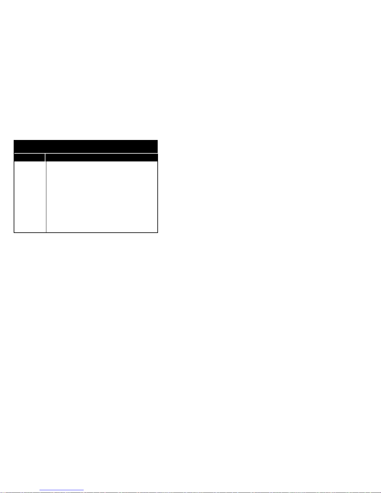
86
Wireless (AMPS) Mode AT Commands
Command Description
!WSTAT? Display operating status information
x1 - Service Available:
0: No
1: Yes
x2 - Roaming Status:
0: Home
1: Roam
x3 - Current System:
0: System A
1: System B
x4 - In Use:
0: No
1: Yes
 Loading...