


DC Series
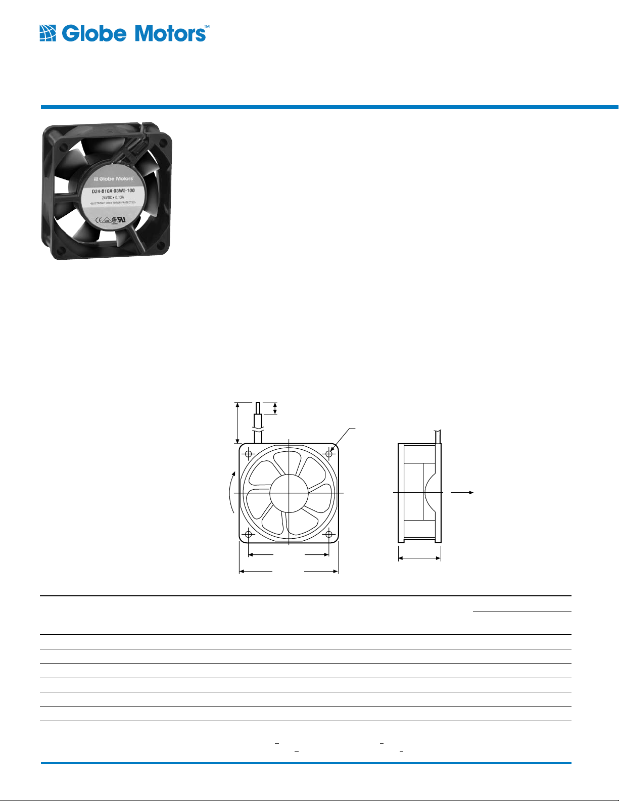
1.97” ± 0.01”
(50 mm ± 0.3 mm)
2.36” ± 0.01”
(60 mm ± 0.3 mm)
LEADWIRE
#24 AWG PER
UL 1007
AIR
.17” ± .04”
(4.3 mm ± 1.0 mm)
11.8” ± 0.6”
(300 mm ± 15 mm)
ROTATION
1.0” ± 0.02”
(25 mm ± 0.5 mm)
0.17” DIA.
(ø4.3 mm)
4 HOLES
2.36" Sq. x 1.00"
Tubeaxial
Cooling Fans
Model No. D24T10
Features
• 7-blade impeller design provides:
Reduced noise
Improved performance
High efficiency
• Solid-state brushless motor design provides:
Auto restart
Low input power
Lower operating voltages
• Precision ball bearing system provides:
Longer life
Higher temperature extremes
Lower noise over time
Maximum shock and vibration resistance
• Designed to meet the rigid standards of
UL, CSA, VDE, and CE.
Accessories:
Finger guards
(60 mm Sq. x 25 mm)
17-23 CFM
(8.0-10.9 L/Sec.)
General Specifications
Frame: Reinforced polybutylene plastic (UL94V0 flame retardant)
Impeller: Reinforced polybutylene plastic
(UL94V-0 rating)
Bearings: Precision, life-lubricated ball bearings
Insulation: Class A integral ground system
rated @ 248°F (120°C)
Weight: 2.3 ozs. (65 grams)
Operating Temperature Range: 14° to 158°F
(-10° to 70°C)
Insulation Resistance: 10 megohms minimum
@ 250 VDC
Dielectric Strength: 500 VAC for 60 seconds
Safety Protection: Electronic locked rotor
protected; polarity protected
Life Expectancy: 75,000 hours minimum
@ 77°F (25°C)
Options: (Consult Factory)
Tachometer output
Locked rotor output sensor
RED LEAD IS POSITIVE (+)
BLACK LEAD IS NEGATIVE (-)
WHITE LEAD IS SENSOR
Globe Motors Part Number Nominal Voltage VAC
D24-B10A-04W3-100 12 6.0 / 13.8 1.44 0.12 3600 28 17 8.0
D24-B10A-04W4-100 12 6.0 / 13.8 2.04 0.17 4550 34 22 10.3
D24-B10A-04W5-100 12 6.0 / 13.8 2.40 0.20 4900 35 23 10.9
D24-B10A-05W3-100 24 10.2 / 27.6 1.68 0.07 3600 28 17 8.0
D24-B10A-05W4-100 24 10.0 / 27.6 2.16 0.09 4550 34 22 10.3
D24-B10A-05W5-100 24 10.0 / 27.6 2.40 0.10 4900 35 23 10.9
*Note: For tachometer output models, substitute “B” in part number. Part Number D24-B10"A”-04W3-100 would change to D24-B10"B”-04W3-100. Minimum order quantity may apply.
For locked rotor sensor output models, substitute “C” in part number. Part Number D24-B10"
32
http://www.globemotors.com/d24t10.pdf
Voltage
Operating
Range VDC Watts Line Amps RPM Acoustic Noise dBA
A”-04W3-100 would change to D24-B10"C”-04W3-100. Minimum order quantity may apply.
Specifications subject to change without notice.
CFM
© 2002 Globe Motors
Airflow (Min.)
Liters per
Second
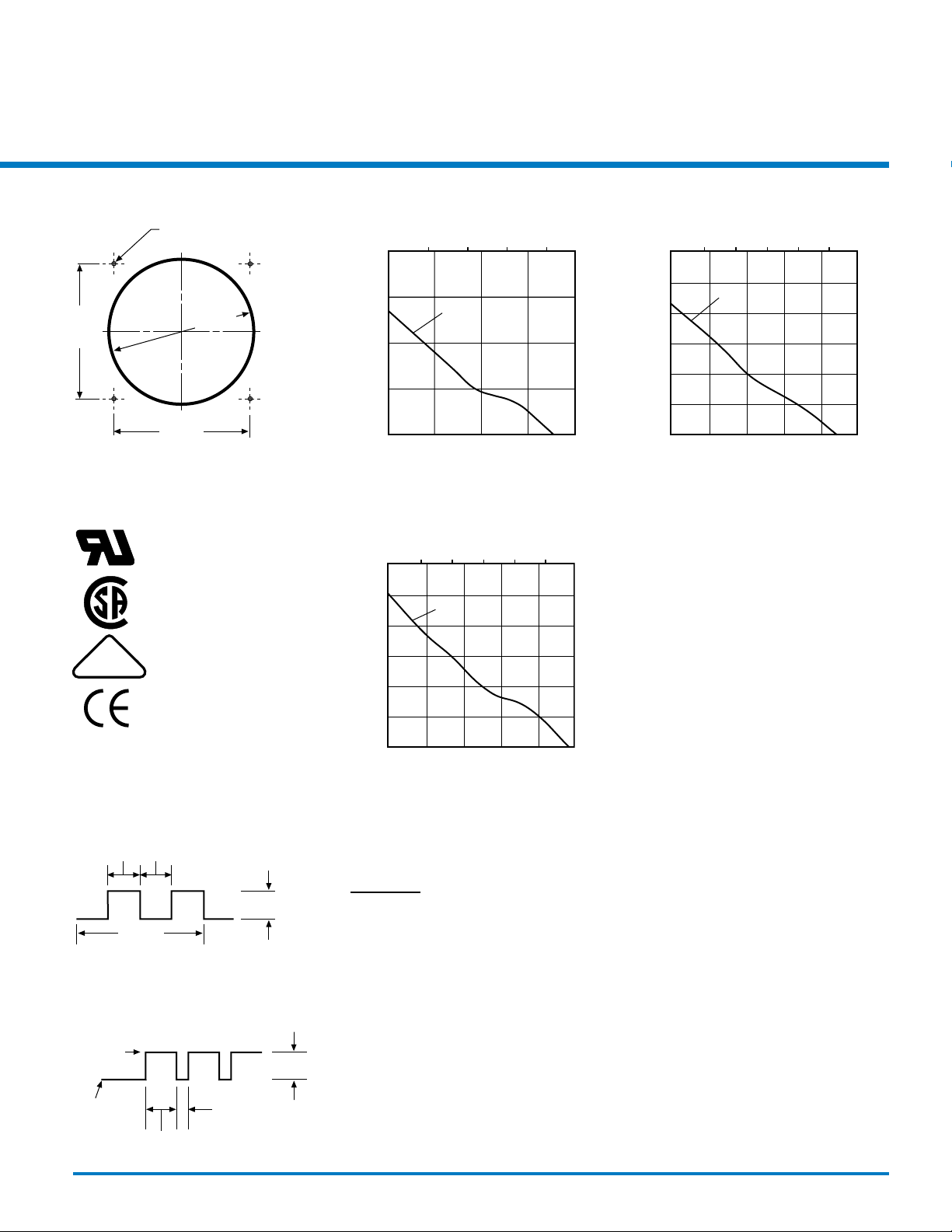
1.97” ± .01”
(50 mm ± 0.3 mm)
1.97” ± .01”
(50 mm ± 0.3 mm)
2.30” DIA.
(ø58.5 mm)
0.17” DIA.
(ø4.3 mm)
4 HOLES
Installation Guide Performance at Sea Level
12.0V
12.0V
12.0V
90°
Up to 30 VDC
90°
One
Revolution
(360°)
Up to
30 VDC
≈ 1 Sec.
Typ.
Locked Rotor
State
Running
State
≈ 7 Sec.
Typ.
Approvals
122525
UL File No.
E105397
CSA File No.
72877
VDE File No.
17074-2611-0706
Airflow – L/Sec.
2
4
.20
.15
.10
.05
6
Static Pressure – In. of Water
0 5 10 15 20
Airflow – CFM
D24-B10A-04W3-100
Airflow – L/Sec.
2
4 8
6
Static Pressure – In. of Water
.30
.25
.20
.15
.10
.05
Airflow – L/Sec.
2
8
.30
4
Static Pressure – MM. of Water
– 4
– 3
– 2
– 1
.25
.20
.15
.10
.05
Static Pressure – In. of Water
0 5 10 15 20 25
8
106
Static Pressure – MM. of Water
– 7
– 6
– 5
– 4
– 3
– 2
– 1
Airflow – CFM
D24-B10A-04W4-100
10
Static Pressure – MM. of Water
– 7
– 6
– 5
– 4
– 3
– 2
– 1
All operating specifications measured at nominal operating
voltage, free air at sea level
24 volt performance is identical to 12 volt fan performance
Tachometer Output
(Open Collector Circuit)
Locked Rotor Output
(Open Collector Circuit)
© 2002 Globe Motors
0 5 10 15 20 25
NOTES:
Specifications subject to change without notice.
Airflow – CFM
D24-B10A-04W5-100
http://www.globemotors.com/d24t10.pdf
33