

Selecting a
two stage, multi-stage
vaneaxial
tubeaxial
propeller
B A
∆P
CFM
0
1 2 3 4
B
A
∆P
CFM
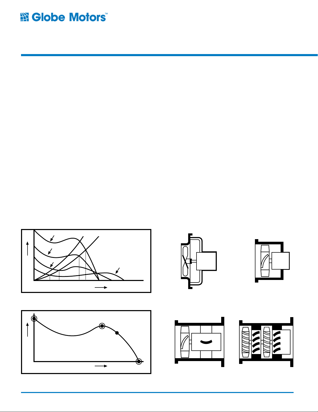
Typical Axial Fan Performance
A1
C
Cooling Fan
As an assistance in selecting the proper
cooling device for your electronic system,
it might be useful to understand the
performance differences among the
various types of axial flow devices.
Figure 1 compares the performance
curves of the four types, all of the same
diameter and operating at the same speed.
Device Characteristics
Axial Flow Devices — propeller fans,
tubeaxial fans, vaneaxial fans, and
multi-stage axial blowers have essentially
the same performance characteristics.
All are distinguished by the fact that
pressure is proportional to lift produced by
the rotating airfoils of the impeller.
As for any airfoil, there is a point (B on
Figure 2) beyond which the impeller
stalls, that is, the pressure (lift) decreases
with decreasing flow. This explains the
dip in the performance curves of each
of these types. It is virtually impossible
to operate satisfactorily in this region, B
to C. Flow pulsations, increased audible
noise, and reduced efficiency occur. Stable
performance and maximum efficiency are
in the A to B range. The optimal operating
range is between A1 and B. This is where
the fan operates best and longest life is to
be expected.
Typical Axial Fan Performance
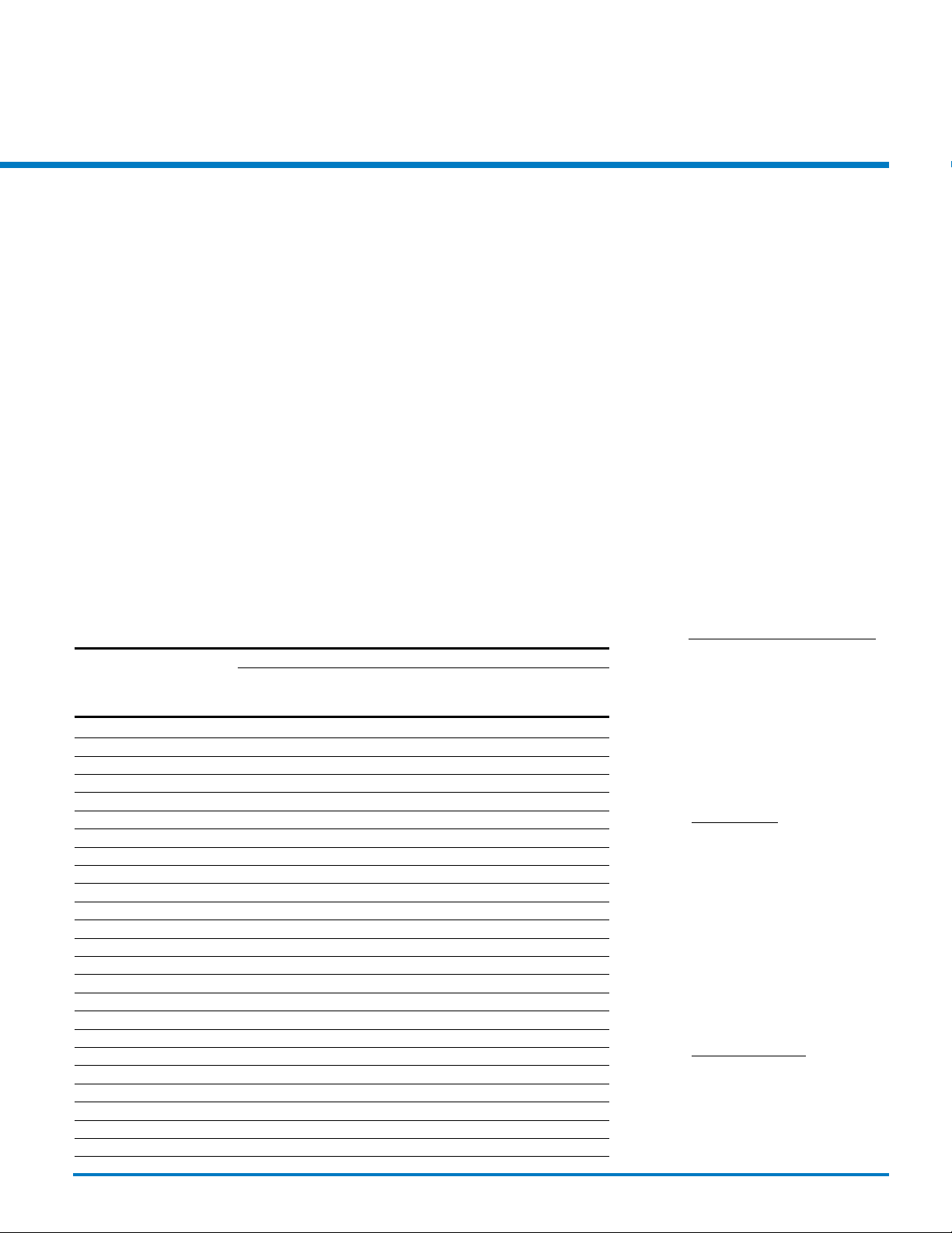
Propeller Fan — consists of a propeller
rotating within a mounting ring or orifice
and includes provision for motor supports.
These are sometimes supplied without the
mounting ring, in which case the customer
mounting panel serves as the fan orifice.
Propeller fans are the simplest, most
economical, and least efficient axial
flow devices.
Tubeaxial Fan — consists of an impeller
rotating within a full cylindrical housing,
which also provides motor support struts.
The term tubeaxial, as presently used by
manufacturers, implies more efficient airfoil
blades, closer tip clearance, and generally
cleaner flow patterns than the propeller fan.
This results in greater pressure capability
and higher efficiency.
Vaneaxial Blower — is the sophisticated
brother of the tubeaxial, just as the tubeaxial
represents an improvement over the
propeller fan. Guide vanes are inclined
on either the inlet or outlet side of the
propeller. The vanes reduce the rotational
or “whirl” pattern of the air stream which
results in:
1. Higher pressure before stall
2. Increased efficiency
Multi-Stage Axial Blower — is essentially
two or more vaneaxial fans mounted on
a common shaft and housing in series.
The first vaneaxial fan, or stage, feeds the
second stage with axial flow at the design
point. Static pressure available is roughly
the product of the number of stages and
stall pressure of a single stage. Multi-stage
units are capable of the highest pressures
attainable by an axial device for a given size
and speed. They are necessarily somewhat
heavier and more expensive than the other
axial units.
For most industrial applications, a tubeaxial
fan provides the best mix of cooling
performance, low noise level, and long,
reliable operation. The fans in this catalog
are tubeaxial. On the following pages, we
provide a simplified approach to selecting
the proper Globe tubeaxial cooling fan for
your system. Globe Motors will provide
technical assistance in solving your
cooling fan requirements that exceed
the capabilities of these tubeaxial fans.
Figure 1.
Figure 2.
6
http://www.globemotors.com/select.pdf
Tubeaxial Fan
Propeller Fan
Vaneaxial Blower
Specifications subject to change without notice.
Multi-Stage Axial Blower
© 2002 Globe Motors
Considerations for the
Cooling Fan Location
A key criterion for fan selection is the
location of the fan in your system. This
has a very important impact on airflow
effectiveness and cooling efficiency.
Globe provides you flexibility with our use
of precision ball bearings. They allow you
to mount our fans in either the horizontal of
vertical position (or somewhere in between)
without negatively impacting bearing wear
and, therefore, life and noise.
Without trying to design your system layout,
here are some general guidelines which we
hope you find helpful:
1. Keep the airflow path as unobstructed
as possible. The air should flow across
components and circuit boards and not
into them. The air entry and exit points
should especially be kept free of
interference to airflow.
2. There are two ways to treat your greatest
sources of heat dissipation.
In a tight cabinet, placing this heat
source near the air exit will have the
least heating effect on the air cooling
your lower power areas. If you have
a large cabinet, like an office copier,
whose interior is relatively uncluttered
but has a significant hot spot, placing
the hot component by the air inlet will
ensure the best cooling. As the air mixes
in the large open cabinet, it will cool
somewhat before exiting past the other
components.
3. To utilize vertical airflow through your
cabinet, place the cooling fan to assist
the natural convection airflow that
moves upward.
4. If you intend to use a filter or an RFI
screen, you must consider the additional
resistance to airflow that these
items create.
By carefully considering your cooling fan
location, you can possibly avoid requiring a
larger fan which would increase your noise
level and power dissipation.
Table 1
Typical Airflow Requirements by End Use Equipment
CFM
0 26 51 76 101 126
to to to to to and
25 50 75 100 125 Up
Office Copiers X X X X X X
Power Supplies X X X X
Micro Computers X X X X
Receivers X X
Terminals X X
Audio Amps X
Pos Terminals X X X
Office Equipment X X X
Recording Equipment X X X
P.A. Systems X X
TV Cameras & Monitors X X
Instrumentation X X X
Medical Equipment X X X
Mini Computers X X
Telecom Equipment X X
Lab Equipment X X X
Computer Peripherals X X X X X
Mainframe Computers X X X
Disc Drives X
Industrial Controls X
Computer Consoles X
Relay Racks X
Instrument Cabinets X
Transmitter Cabinets X
How to Select a Globe Cooling Fan
To aid you in determining your cooling fan
requirements, we would like to provide a
simplified approach to fan selection.
Table 1 provides a general starting point for
typical airflow requirements of industrial
equipment. The following discussion
will enable the user to apply a clear
understanding of airflow in selecting a
suitable unit.
The Essentials
To properly select a particular fan for
a specific application, the detailed
requirements must be known. These
include the normal motor specifications
and those peculiar to air-moving devices,
your system's power dissipation, your
system's resistance to airflow, and the
allowable temperature of your system's
internal air.
Cooling Air Required
The values established by the method
described below tend to be conservative.
For example, the method treats laminar
airflow only. When turbulent flow conditions
exist, the cooling is improved further.
CFM =
watts dissipated x a constant
allowable temperature minus
inlet temperature °F
Standard Air Conditions — Air density,
for many applications, is taken at standard
conditions (70°F at 29.92" of mercury).
The constant 3.16 is a function of the
specific heat of air at these standard
conditions. The formula for standard air
conditions is:
Equation 1.
CFM = x 3.16
watts
Temp. Rise °F
Variable Density — When standard air
conditions cannot be assumed, you may
use the constant 0.1784 as a function
of the specific heat of air near sea level.
Change in the specific heat due to
pressure and temperature changes has
not been considered, and in most cases
it is negligible. However, you might want
to consider high altitude usage, such as in
Denver. To calculate CFM for these nonstandard air conditions, use the formula:
Equation 2.
CFM = x 0.1784
watts x T°R
Temp. Rise °F x Pb
watts = watts dissipated
T°R = Temperature in °Rankine
temperature = 459.6 + °F
Pb = barometric pressure in inches
of mercury
© 2002 Globe Motors
Specifications subject to change without notice.
http://www.globemotors.com/select.pdf
7
 Loading...