

Globel GL6000 Assembly Instructions Manual
GARDEN SHED
Assembly Instructions
Skillion Roof
Suitable for Models:
5'w x 3'd 6'w x 3'd 6'w x 4'd
8'w x 3'd 8'w x 4'd
© Globel Industries Pty Ltd
GI00045 September 30 2015
E N G L I S H
© Globel Industries Pty Ltd
GI00045 September 30 2015
Choking Hazard - This product contains small parts.
It's Not That Difficult!
IMPORTANT! Read These Instructions FIRST.
The construction of your shed isn't as complicated as it may first appear.
Our step by step, illustrated instructions are easy to follow, and we provide hints
to make the assembly even easier. Simply follow our recommendations and carefully study
our illustrations, then your garden shed will be assembled quickly and accurately.
Make sure the site you choose for your garden shed is firm and level, and water drains away from the site.
Do not install the garden shed in areas subject to high winds.
Do not assemble the garden shed on a windy day.
Your garden shed should be assembled on a specifically prepared base, ie concrete slab or pavers (or a suitable
Garden Shed Foundation Kit) and then secured using the recommended dyna bolts as listed in the "Tools Required" page.
A heavy duty polythene sheet should be placed under the foundation to assist in reducing rising dampness from the soil,
thus reducing condensation build up in your garden shed.
Once secured, we highly recommend applying silicone along the inside of the base rail to prevent water from seeping under
the base frame and into your shed.
Do not backfill against the shed's walls or base, as this will cause corrosion and void the warranty.
Check the labelling on the Parts Cartons to ensure you have the shed model you ordered, and the correct
number of Parts Cartons.
For simplicity, in most part, this manual illustrates the construction of a 6' wide x 4' deep garden shed,
with additional instructions for 5' and 8' wide garden sheds inserted where applicable.
TOOLS INFORMATION:
The tools you need are shown in the "TOOLS REQUIRED" section as all holes for screws and nuts and bolts are pre-drilled
(excluding one hole only, which will require a 3mm drill bit) you will only need a power screw driver or a cordless drill with
a magnetic Phillips-head tip to make the assembly quicker and easier.
Do not over-tighten self-tapping screws.
Nuts can be tightened by holding your finger on them as you tighten the bolt with the power screw driver no spanner needed.
CHECK THE PARTS:
Before you start, separate and identify all the parts and hardware. (Refer to Parts List diagrams in the following pages).
WARNING: Edges are sharp - Handle with care - Using gloves is highly recommended.
WE RECOMMEND you get a second pair of hands to assist you with the assembly.
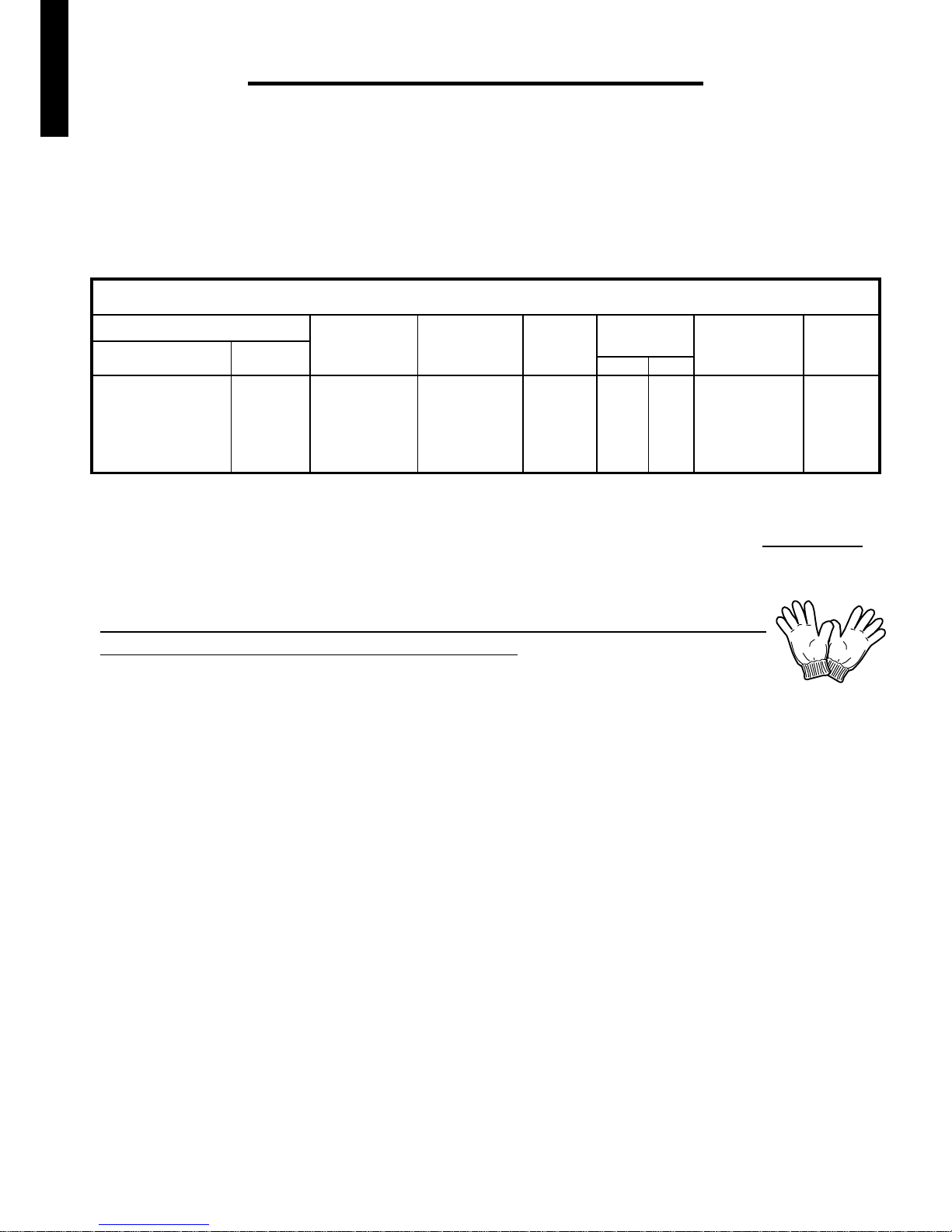
INSTALLATION ADVICE
Garden Shed Specifications
SHED TYPE / SIZE BASE DIMENSIONS
(Front x Sides mm)
ROOF DIMENSIONS
(Front x Sides mm)
WALL SHEET
HEIGHT
mm
Front Back
OVERALL HEIGHT mmDOOR OPENING
(Height x Width mm)
No. CARTONS
(Weight Kg)
Size (Feet)Type
Double Sliding Doors 5 x 3 1400 x 820 1480 x 930 1780 1935 1700 x 590 1 (40)1785
Double Sliding Doors 6 x 3 1710 x 820 1800 x 930 1780 1935 1700 x 625 1 (43)1785
Double Sliding Doors 6 x 4 1710 x 1130 1800 x 1240 1780 1975 1700 x 625 1(50)1785
Double Sliding Doors 8 x 3 2340 x 820 2420 x 930 1780 1935 1700 x 1050 2 (55)1785
Double Sliding Doors 8 x 4 2340 x 1130 2420 x 1240 1780 1975 1700 x 1050 2 (60)1785
1
E N G L I S H
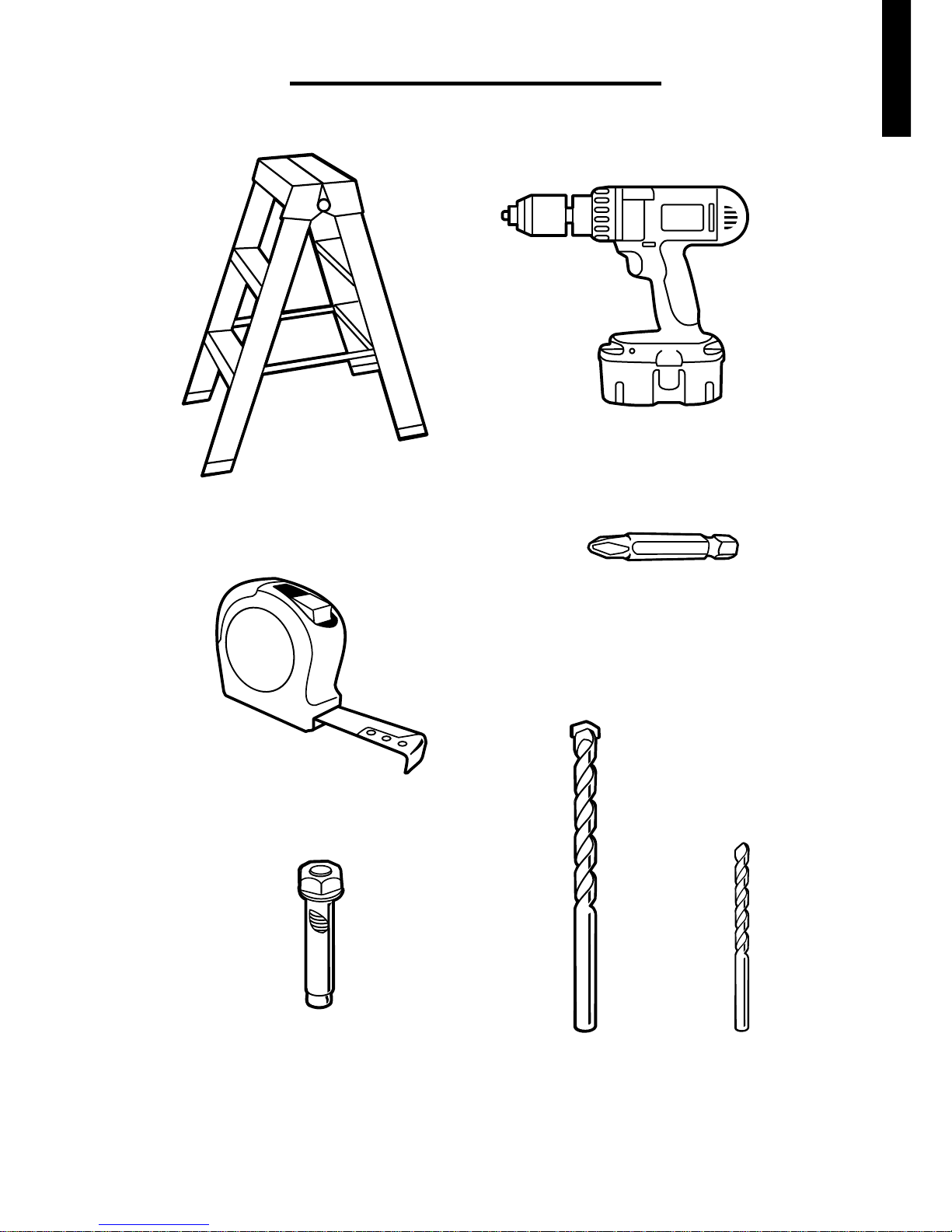
TOOLS REQUIRED
Step Ladder
Tape Measure
Phillips-Head
Screw Driver Bit
(P2)
Battery Power Drill
Dyna Bolts
(not supplied)
6.5mm x 36mm
recommended
2
Masonry
Drill Bit
6.5mm
Steel
Drill Bit
3mm
© Globel Industries Pty Ltd
GI00045 September 30 2015
E N G L I S H
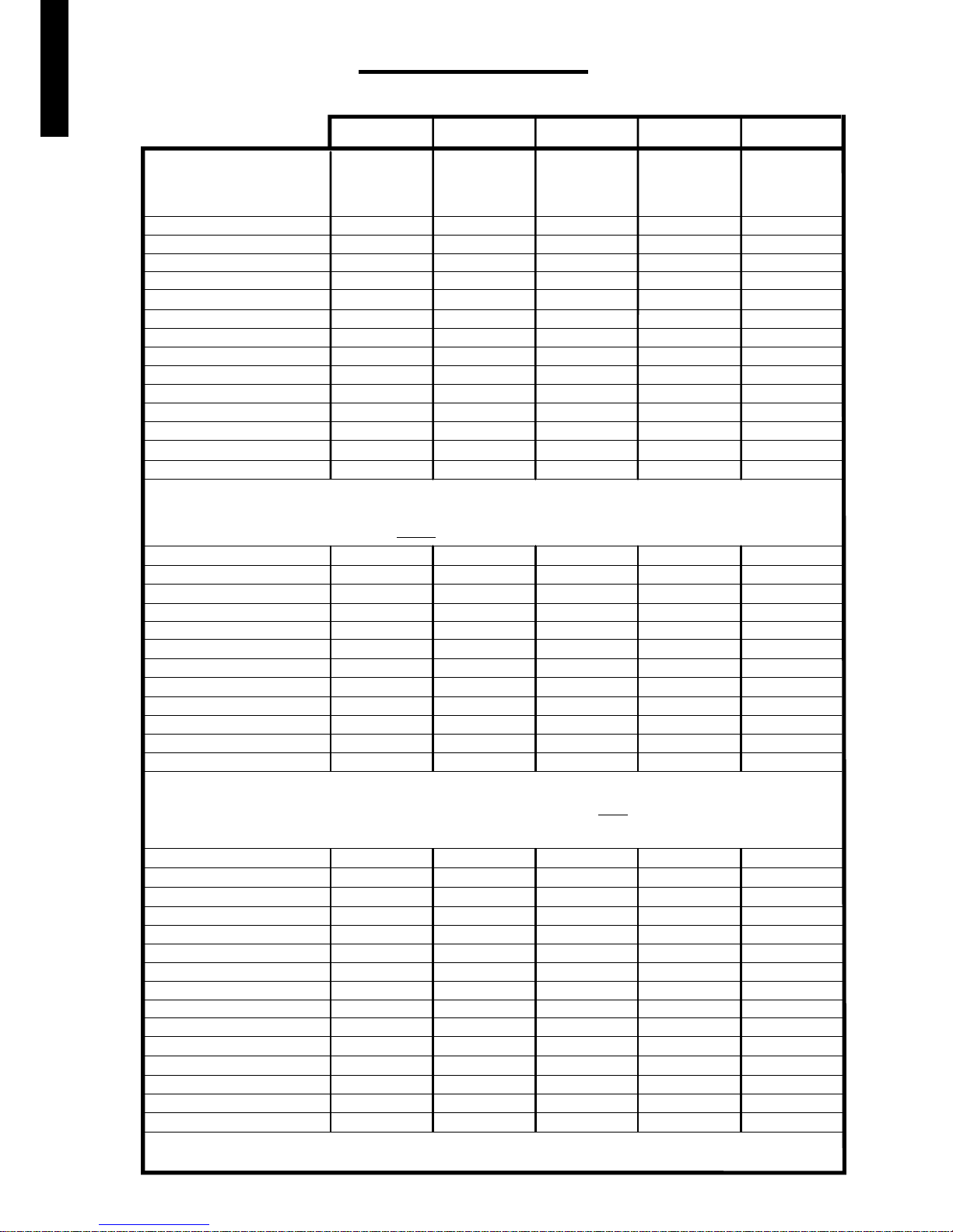
PARTS LIST
SPECIFIC TO MODEL SIZES LISTED
3
5' x 3'
6' x 3'
6' x 4' 8' x 3' 8' x 4'
Roof Corner Cap
Corner Brace
Left Top-Wall Rail Bracket
Right Top-Wall Rail Bracket
Door Glide
Door Glide Roller
Door Spacer
Door Handle
Screws
Nuts
Bolts
Washers
HARDWARE KIT
NOTE: Hardware Kit is packed in Carton '1' for all models
4
6
2
2
4
16
4
2
1 x bag
1 x bag
1 x bag
YES
4
6
2
2
4
16
4
2
1 x bag
1 x bag
1 x bag
YES
4
6
2
2
4
16
4
2
1 x bag
1 x bag
1 x bag
YES
4
6
2
2
4
16
4
2
1 x bag
1 x bag
1 x bag
YES
4
6
2
2
4
16
4
2
1 x bag
1 x bag
1 x bag
YES
Corner Panel
Wall Sheet (Full)
Wall Sheet (Half)
Door Jamb
Roof Sheet (Full)
Roof Sheet (Half)
Door
Roof Starter (Left)
Roof Starter (Right)
Front Fascia Panel
CARTON '1' QTY
4
3
1
2
2
2
1
1
1
QTY
4
4
2
2
1
2
1
1
1
QTY
4
4
2
2
2
1
2
1
1
1
QTY
4
5
2
2
3
1
2
1
1
1 x Left & 1 x Right 1 x Left & 1 x Right
QTY
4
5
4
2
3
1
2
1
1
Above Door Fascia
Door Brace (Top & Bottom)
Gable (Left)
Gable (Right)
1
2 of each
1
1
1
2 of each
1
1
1
2 of each
1
1
1
2 of each
1
1
1
2 of each
1
1
CARTON '2' - (8' wide wide models only)
NOTE:
Carton '2' parts as listed below for 5' wide and 6' wide models are packed in Carton '1'.
Base Rail (Front)
Base Rail (Back)
Side Base Rail (Left)
Side Base Rail (Right)
Front Mid-Wall Brace (Left)
Front Mid-Wall Brace (Right)
Side Mid-Wall Brace
Back Mid-Wall Brace
Right Side Top-Wall Rail
Left Side Top-Wall Rail
Front Top Rail
Back Top Rail
Front Roof Trim
Back Roof Trim
Entry/Exit Ramp
1
1
1
1
1
1
2
1
1
1
1
1
1
1
1
1
1
1
1
1
1
2
1
1
1
1
1
1
1
1
1
1
1
1
1
1
2
1
1
1
1
1
1
1
1
1
1
1
1
1
1
2
1
1
1
1
1
1
1
1
1
1
1
1
1
1
2
1
1
1
1
1
1
1
1
© Globel Industries Pty Ltd
E N G L I S H
GI00045 September 30 2015
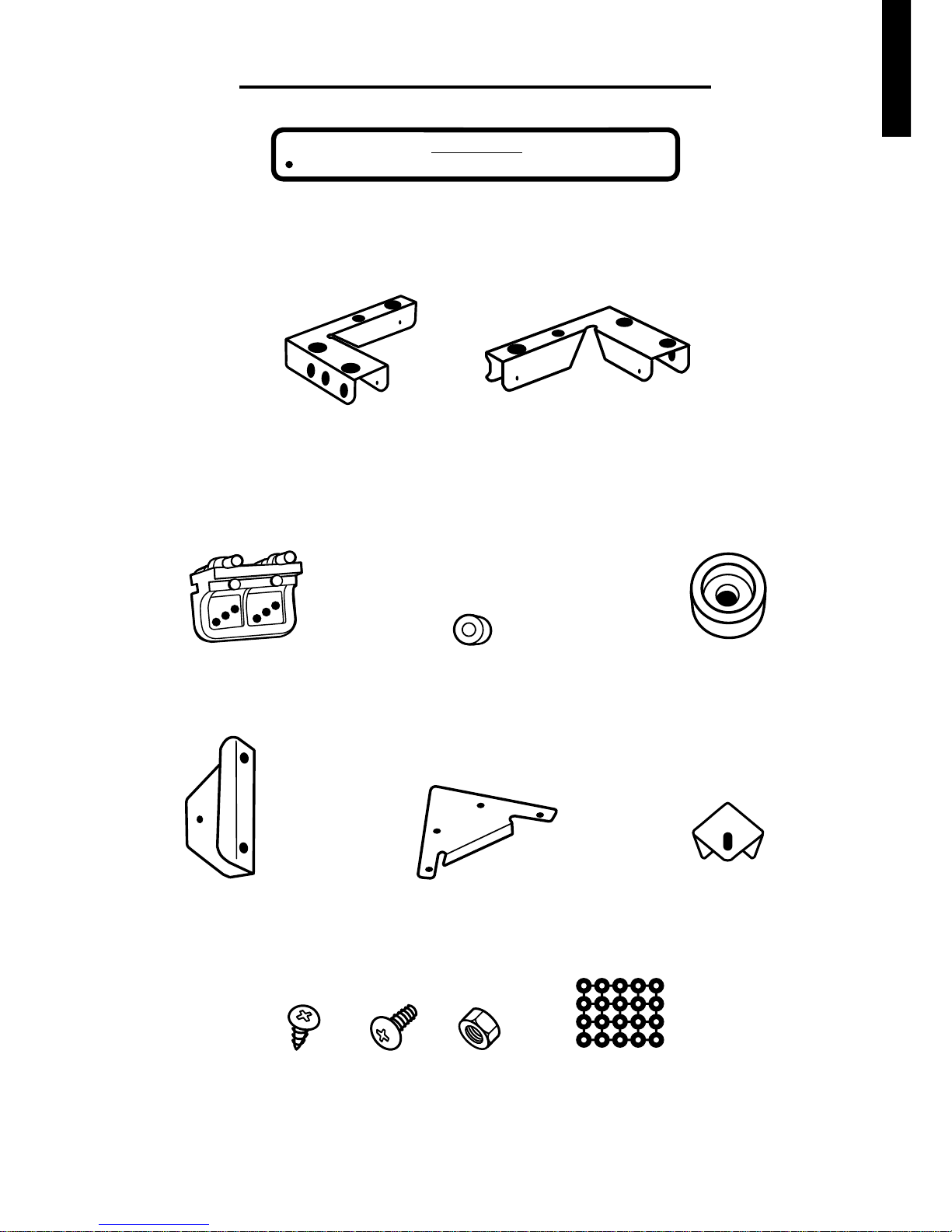
WASHERS
SCREW BOLT NUT
DOOR SPACER
DOOR GLIDE
DOOR ROLLER
ROOF
CORNER CAP
CORNER BRACEDOOR HANDLE
4
PARTS LIST - Hardware Kit
CHOKING HAZARD -
This product contains small parts.
WARNING
LEFT FRONT & BACK
TOP-WALL RAIL
BRACKET
RIGHT FRONT & BACK
TOP-WALL RAIL
BRACKET
© Globel Industries Pty Ltd
E N G L I S H
GI00045 September 30 2015
DOOR BRACE
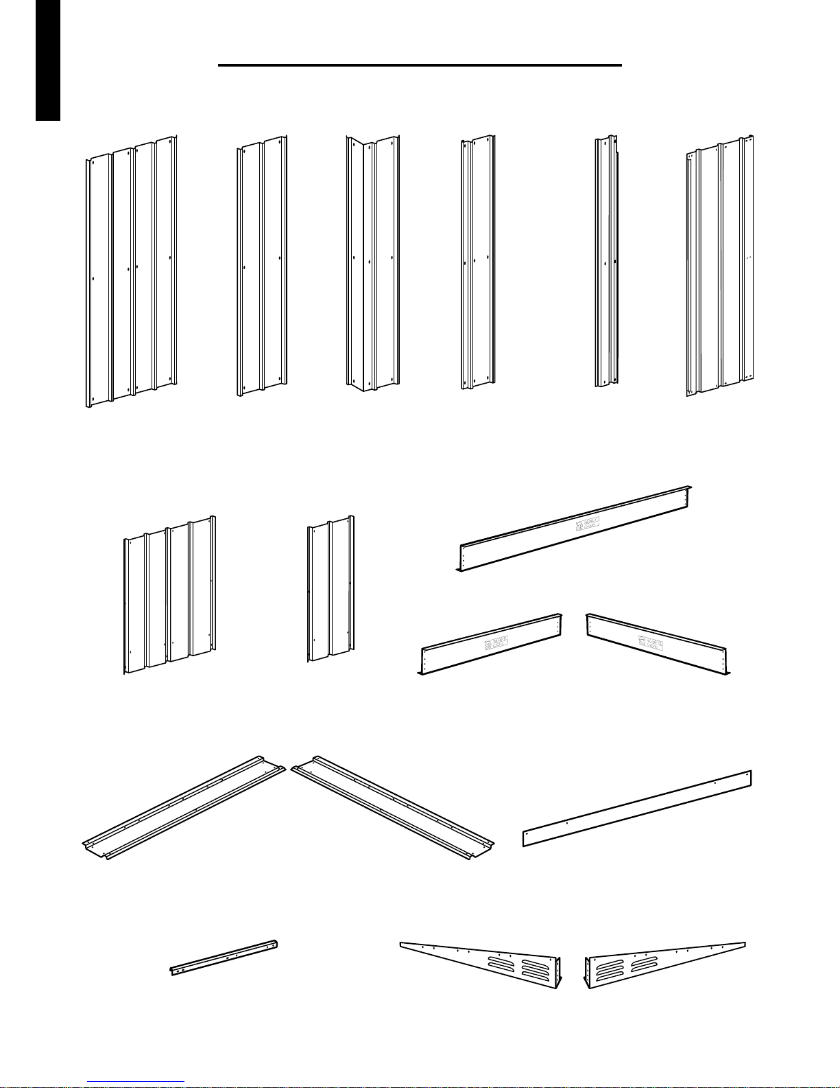
PARTS LIST - Carton '1'
CORNER
PANEL
FULL
WALL SHEET
HALF
WALL SHEET
DOOR JAMB
(5' & 6' WIDE
SHEDS ONLY)
DOORDOOR JAMB
(8' WIDE
SHEDS ONLY)
LEFT
ROOF STARTER
RIGHT
ROOF STARTER
RIGHT GABLELEFT GABLE
HALF
ROOF SHEET
FULL
ROOF SHEET
5
ABOVE DOOR FASCIA
FRONT FASCIA PANEL
(5' & 6' WIDE SHEDS ONLY)
(8' WIDE SHEDS ONLY)
LEFT
FRONT FASCIA PANEL
RIGHT
FRONT FASCIA PANEL
E N G L I S H
© Globel Industries Pty Ltd
GI00045 September 30 2015
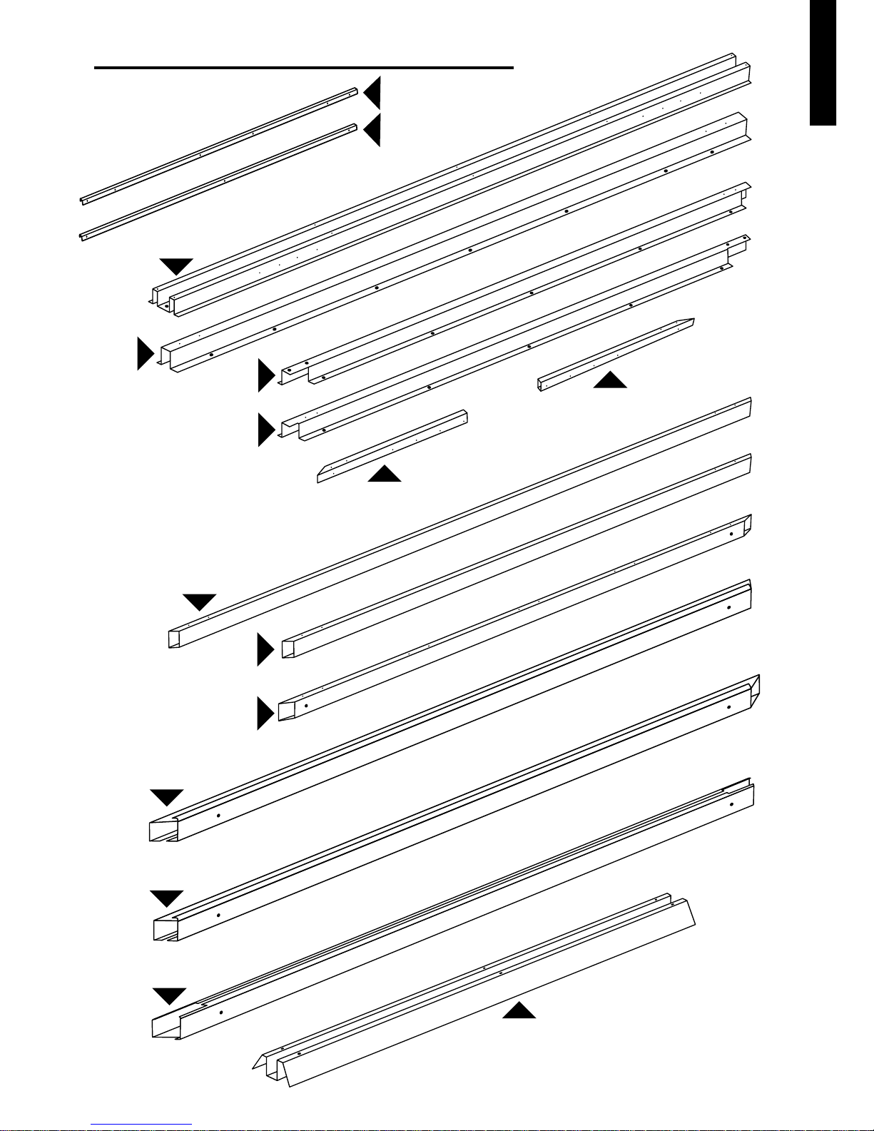
FRONT
TOP RAIL
LEFT
TOP-WALL RAIL
RIGHT
TOP-WALL RAIL
ENTRY/EXIT RAMP
6
FRONT
BASE RAIL
LEFT
SIDE BASE RAIL
RIGHT
SIDE BASE RAIL
LEFT FRONT MID-WALL
BRACE
RIGHT FRONT MID-WALL
BRACE
BACK
TOP-WALL RAIL
BACK
MID-WALL BRACE
BACK
BASE
RAIL
SIDE
MID-WALL BRACE
PARTS LIST - Carton '2'
BACK ROOF TRIM
FRONT ROOF TRIM
E N G L I S H
© Globel Industries Pty Ltd
GI00045 September 30 2015
FORMWORK
FORMWORK
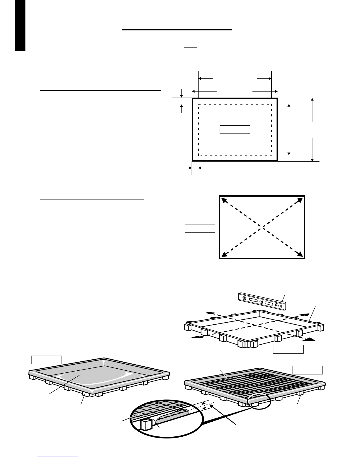
FOUNDATIONS
Your shed requires a solid foundation.
If you need to construct a concrete slab, this page shows the method and dimensions we recommend.
Make sure the slab area is square
by ensuring diagonal corner dimensions
are equal.
(Diagram B)
Formwork
must be100mm thick and level. (Diagram C)
First, lay builders plastic on the ground as a
barrier to rising moisture. (Diagram D)
Then place F52 reinforcing steel mesh on top of
the builders plastic, ensuring the steel mesh is
raised off the plastic to a depth of approximately
half the thickness of the formwork. (Diagram E)
Then pour the concrete and allow five days to cure.
ROOF WIDTH
SLAB WIDTH
ROOF
DEPTH
SLAB
DEPTH
SLAB DIMENSIONS
100mm
100mm
Diagram A
Determine the size of the concrete slab
by adding 100mm to the width and 100mm
to the depth of the roof size of the shed.
(See Diagram A).
Adding the additional 100mm prevents
rainwater from the roof creating a trench,
and splashing soil against the walls of the
shed, which could cause corrosion.
A
B
C
MEASUREMENT 'X' = MEASUREMENT 'Y'
SLAB
AREA
X
Y
Y
X
Diagram B
Diagram C
FORMWORK
SPIRIT LEVEL
FORMWORK
BUILDERS
PLASTIC
Diagram D
F52 REINFORCING
STEEL MESH
MESH RAISED TO
APPROXIMATELY HALF
THICKNESS OF FORMWORK
F52
REINFORCING
STEEL MESH
Diagram E
7
E N G L I S H
© Globel Industries Pty Ltd
GI00045 September 30 2015
DOOR
GLIDE
ROLLER
SPINDLE
Diagram 1
Diagram 2
DOOR GLIDE.
NOTE:
CURVED SIDE
FACING FRONT FACE
OF TOP RAIL
DOOR
GLIDE
SLOT
SLOT
FRONT FACE
OF TOP
RAIL
TOP RAIL
(FRONT)
FLANGE
FRONT FACE
OF TOP RAIL
SLOT
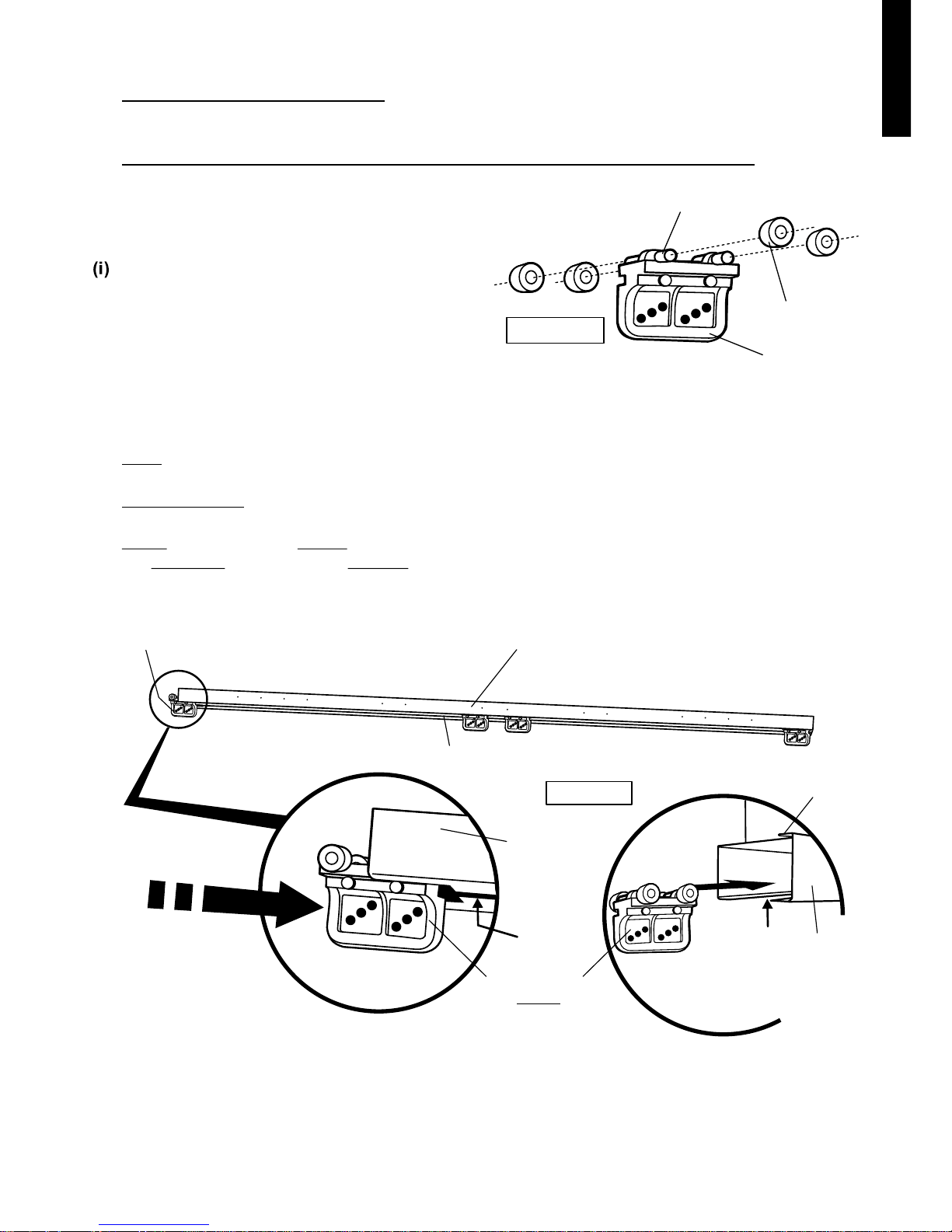
Pre-Assembly
FRONT TOP RAIL AND DOOR GLIDES
Slip the four rollers onto the four spindles
of each of the four door glides as shown in
Diagram 1.
(ii) Slide the four door glides with rollers attached,
into the slot under the front top rail.
Hint: Front top rail is the longest of the three
aluminium rails.
IMPORTANT: Make sure rollers don't slip off.
8
Note: The door glides MUST be positioned with
the CURVED side facing the FRONT face of
the top rail as shown. See Diagram 2.
E N G L I S H
© Globel Industries Pty Ltd
GI00045 September 30 2015
 Loading...