

Page 1
Assembly manual for
Black Snapper XS
Seite 1 von 5
Assembly manual Black Snapper XS
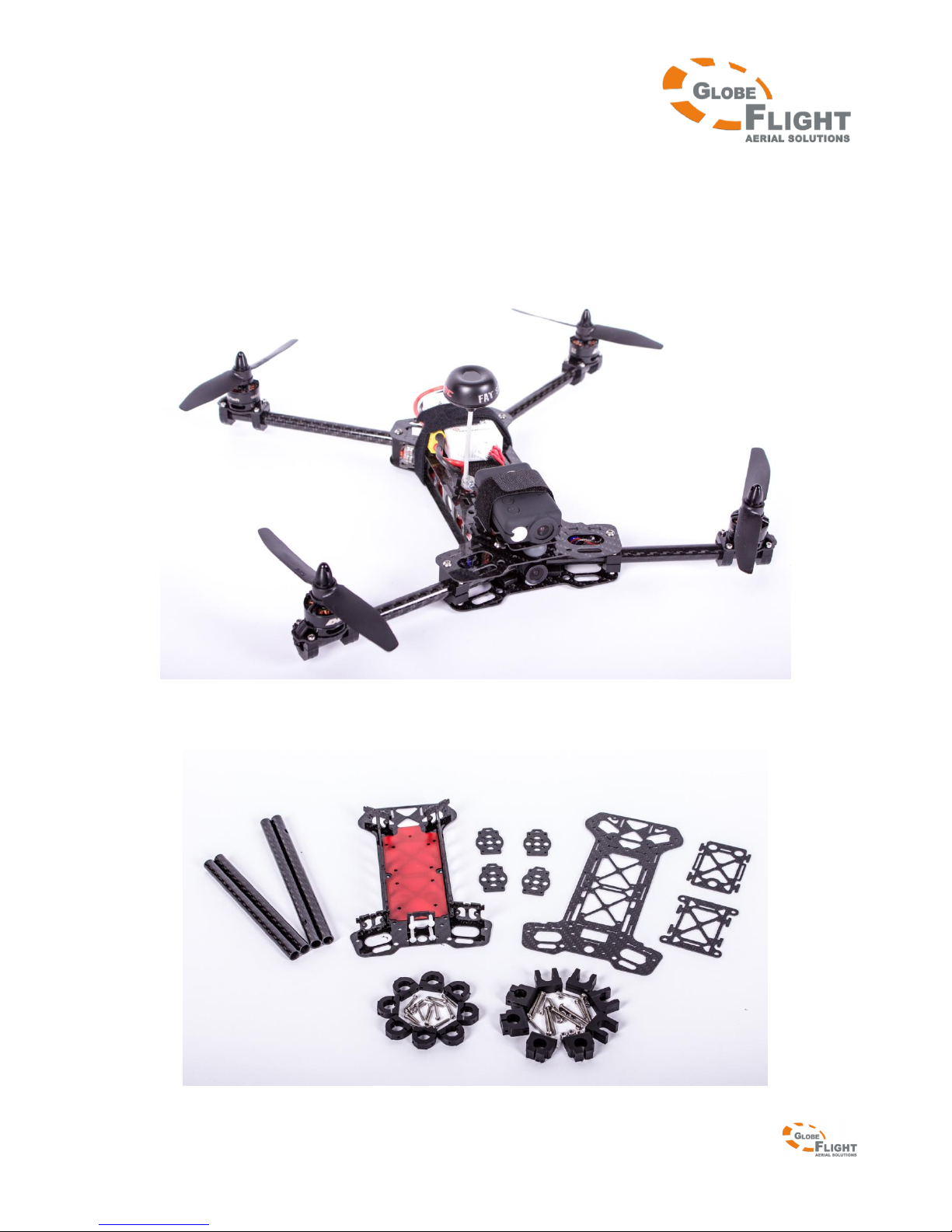
In the box:
Page 2
Assembly manual for
Black Snapper XS
Seite 2 von 5
We recommend that you test-fit all components first, the long booms should be mounted to the rear end and the
short booms to the front end. Doing so, you can measure the approximately required cable length und cut them.
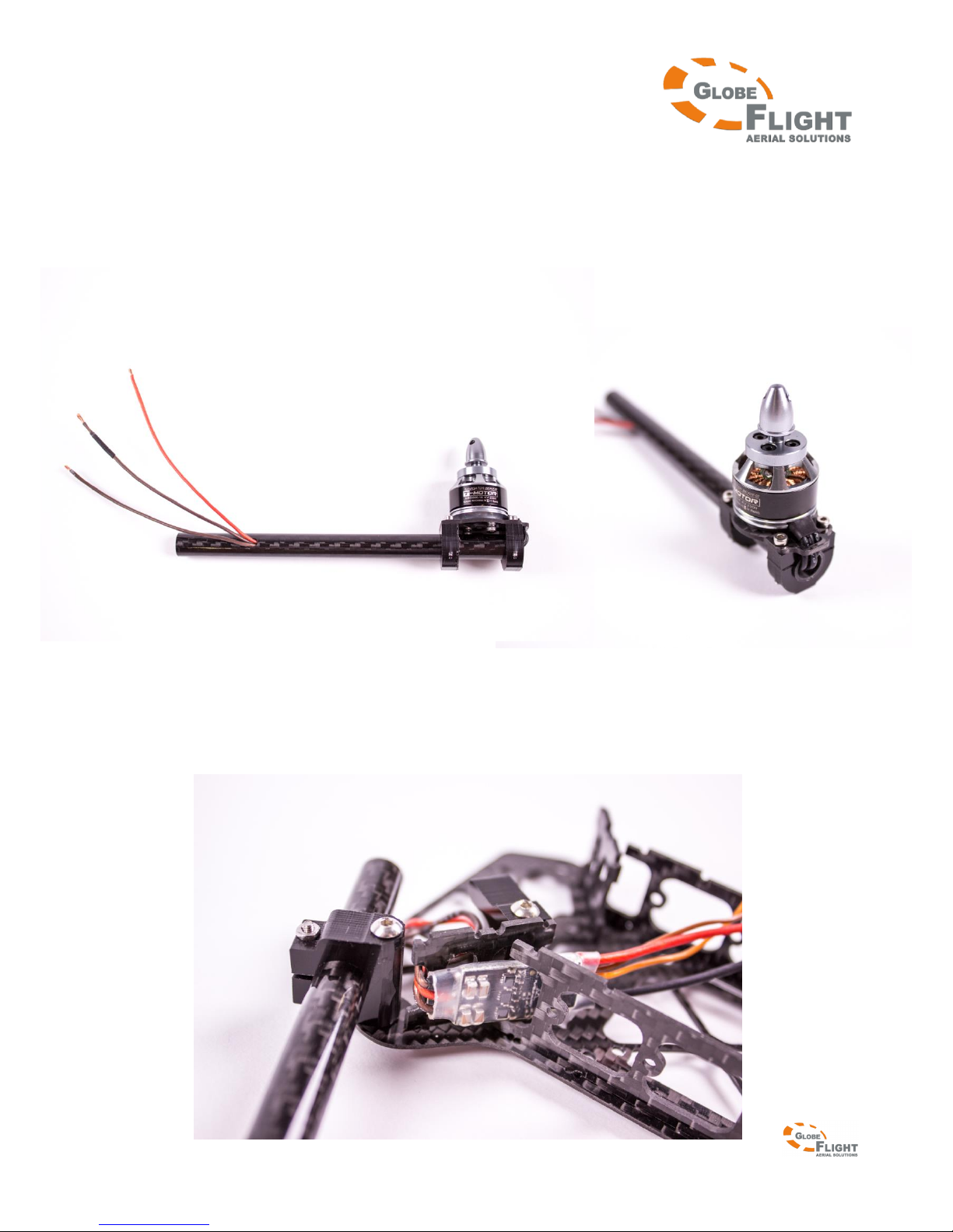
1. Mounting and wiring of the motors
Threading the motor cables through the booms can be done easier when the motors aren’t mounted yet. Just gently
push the cables through the boom until the wire ends reach the side hole. There, you lift the cables with a pair of
tweezers from the inside of the boom to the outside while still pushing the cables forward. You can protect the
cables with additional heat shrink tube at the two spots where they might be damaged by sharp edges.
2. Soldering and mounting of the ESCs
Make sure that you use an appropriate cable length between boom and ESC. The cables should be bent in a half
circle which has to be large enough that the cables won’t be pulled in any direction when you use the folding
mechanism. This means that the cables have to be long enough so they don’t get worn in the long term, but they
shouldn’t be too long at the same time because then they could get squeezed. Please work very precisely here. The
ESCs can simply be attached with double-sided tape.
Page 3
Assembly manual for
Black Snapper XS
Seite 3 von 5
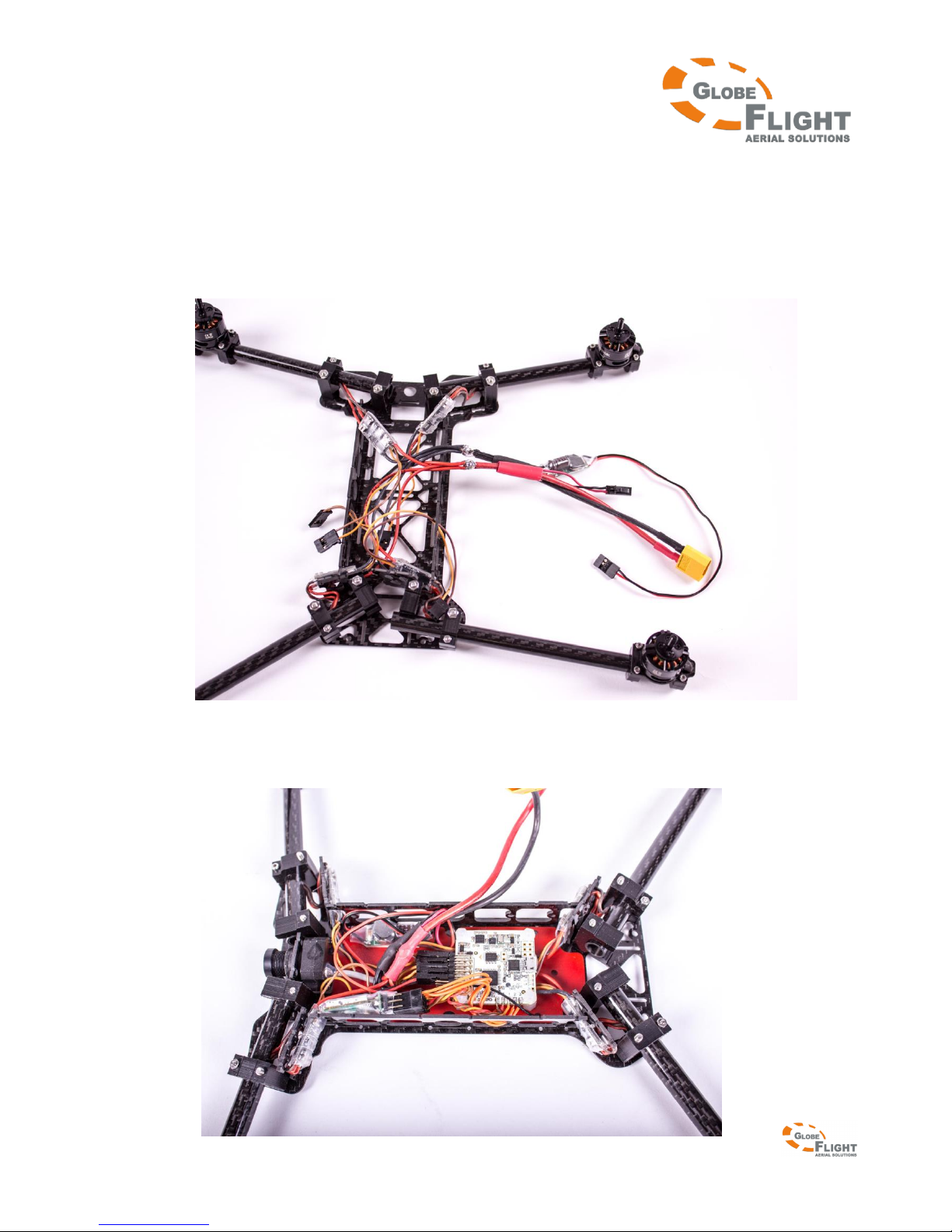
3. Soldering of the cable harness
You can either use a circuit board or solder a cable harness for power distribution. In this case, we chose the
soldering option to save space and weight. Please also solder e.g. a BEC for the Naze 32 and the power supply for the
video transmitter. You may also take into consideration that you attach reserved connections for possible additional
modules.
4. Mounting the flight control, FPV camera and receiver
Pay attention to the correct orientation of the flight control (the arrow on the Naze 32 board must point to the nose
of the aircraft)
Page 4
Assembly manual for
Black Snapper XS
Seite 4 von 5
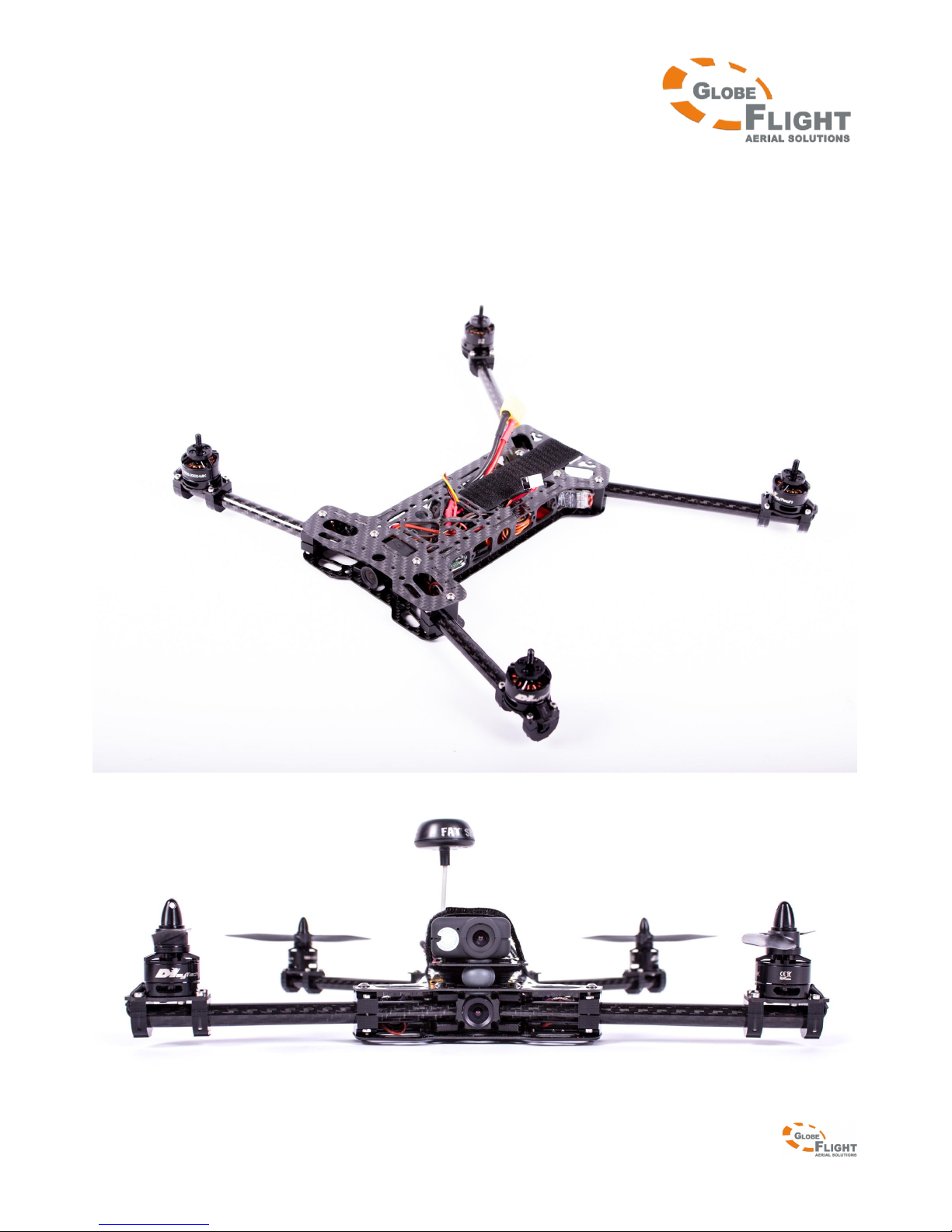
5. Closing the frame and adjusting the motors
Please make sure that all side wall parts fit neatly into the prepared slots bevor you tighten the srews and that the
long booms are mounted to the rear frame end. When you successfully closed the main frame, please adjust the
alignment of the motors and tighten the screws which secure the booms from accidental twisting. The motor axes
must be aligned perfectly vertical!
6. Mounting the propellers, video transmitter, battery and Full HD camera (optional) and adjusting the CoG.
Page 5

Assembly manual for
Black Snapper XS
Seite 5 von 5
The position of the CoG can be found out like described:
You connect the center points of the motor axes of both front and rear motors with a virtual line, so that you get 2
parallels. The half distance between these two parallels marks the center of thrust. You can adjust the CoG to match
this point by moving the battery, video transmitter and Full HD camera. Thereby you can equally distribute the
weight, so that all motors need the same power to keep the aircraft hovering.
From the mechanical perspective, your Black Snapper XS is now ready to fly!
We wish you a lot of fun during the build and of course later in the air with your Black Snapper XS!
 Loading...