

Page 1
4077 Airpark Dr. Standish, MI 48658 • 989-846-4583 • www.globesprinkler.com
Technical Support • 989-414-2600 • techservice@globesprinkler.com
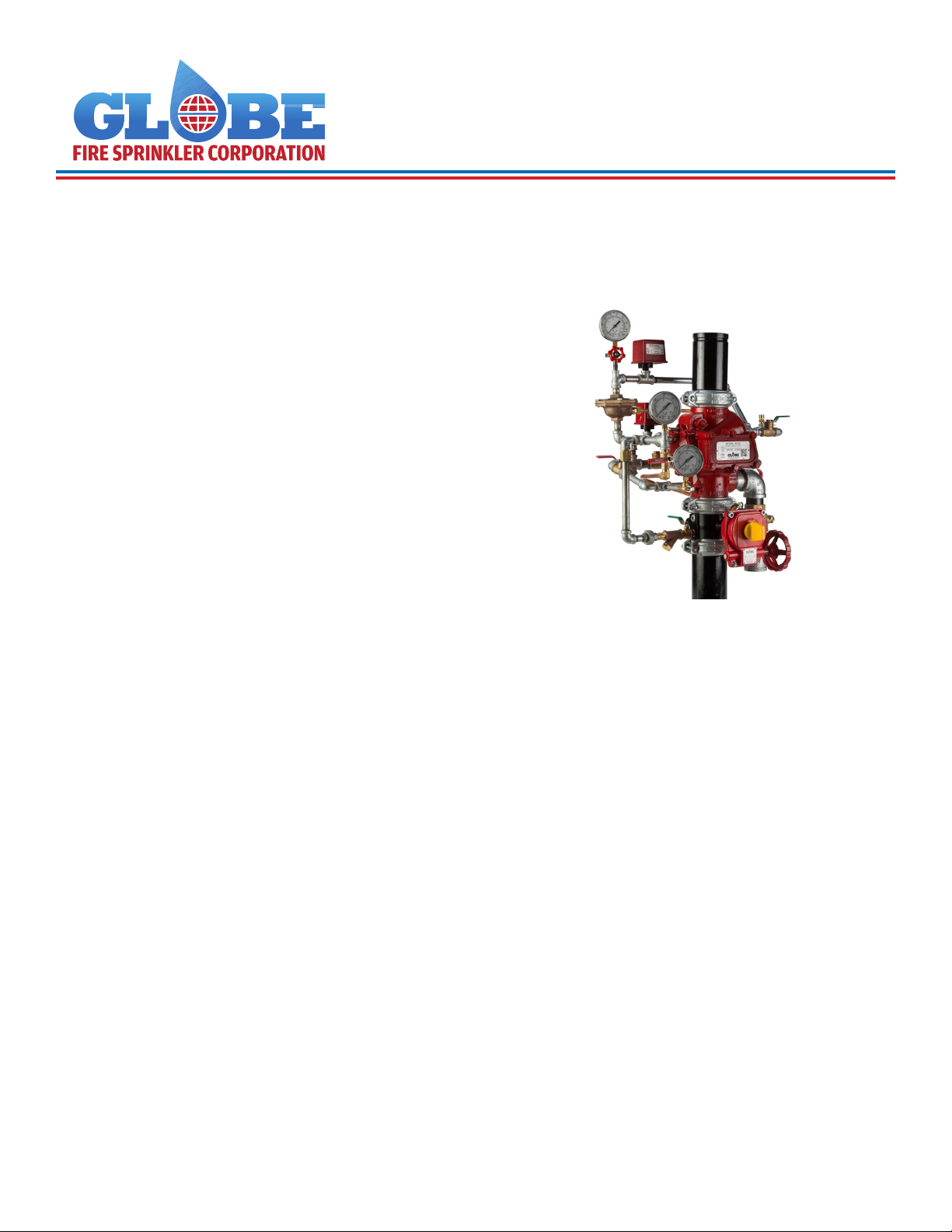
MODEL RCW DRY SYSTEM VALVE
GENERAL DESCRIPTION
The Globe Model RCW* dry valve is a hydraulically operated external resetting differential latching style valve. The
Model RCW dry valve is used as an automatic water control
valve in dry applications. The Model RCW dry valve serves
as the primary water control valve installed in the water
supply to a dry sprinkler system incorporating automatic
(closed) sprinklers with compressed air or nitrogen within
the system piping.
Setting of the Model RCW dry valve requires water pressure
in the pressure chamber being maintained on the plunger
rod. The pressure on the plunger rod forces the lever arm/
roller assembly against the clapper which in turn keeps
the supply water from entering the sprinkler system piping. Water pressure is provided to the pressure chamber
through a connection to the main water supply at a point
upstream of the system main control valve. This connection
also supplies water pressure up to the dry pilot actuator.
The dry pilot actuator is held closed when in the normal set
condition by air pressure in the system piping. When system
air pressure is relieved via one or more operated sprinklers,
the dry pilot actuator will open, allowing the pressurized
water to be evacuated from the pressure chamber.
In the standby condition, the valve is normally closed and
will automatically activate (trip) upon the activation of an au-
tomatic sprinkler, as a result of a re condition. The RCW
valve may also be operated by means of a manual release,
which is provided in the trim, to override the normal activation sequence described above.
When heat from a re opens an automatic sprinkler, water
pressure in the pressure chamber decays resulting in the
movement of the push rod assembly, releasing the lever
arm/roller assembly from the clapper. The system water
supply pressure forces the valve clapper open resulting in
water ow into the system piping. Upon system activation,
re alarm signaling is provided by means of owing water
through the alarm port/intermediate chamber and associ-
ated alarm line trim. The ow of water activates a pressure
switch which in turn noties local alarms and/or an alarm
signaling monitoring service. After the main control valve
has been shut, the system drained, and any operated
sprinklers replaced, the RCW dry valve is easily set/reset by
means of pushing the reset knob. The system is now ready
for the introduction of compressed air back into the system
piping.
If the speed of operation of the dry valve needs to be increased, an optional accelerator can be utilized to decrease
the trip time of the valve from the operation of a sprinkler or
the inspectors test connection.
MODEL RCW DRY SYSTEM VALVE
TECHNICAL DATA
Approvals
• cULus
• FM
Maximum System Working Pressure
• 300 psi (20.6 Bar)
End Connections
• Groove x Groove
Materials of Construction
• See Technical Datasheet H-1 for materials of
construction for the Model RCW Valve
*Patents Pending
MAR 2018 GFV-305 (Formerly H-3) Page 1 of 11
Page 2
MODEL RCW DRY SYSTEM
The dry system trim is one optional trim arrangement for
the Globe Model RCW valve. This arrangement is typically
utilized when the system is subject to areas exposed to
freezing or close to freezing temperatures. With this conguration, the detection system consists of automatic sprinklers spaced throughout the protection area. System air
pressure is used to ensure the integrity of the system piping
and used as the activation method for the valve.
Water pressure is maintained in the valve pressure chamber
up to the dry pilot actuator through a restricted connection
from the main water supply which is taken upstream of the
system main control valve (The pressure chamber supply
valve must remain in the open position at all times when the
system is in service). The dry pilot actuator is normally held
in the closed position by the system air pressure supplied
through the automatic air or nitrogen maintenance device.
When an automatic sprinkler operates, the air ow rate
through the open sprinkler is at a ow rate greater than that
which can be supplied through the automatic air or nitrogen
maintenance device. This causes a pressure drop in the
system and the upper chamber of the dry pilot actuator. An
optional accelerator can increase the rate at which the air
decays on the dry pilot actuator, if a faster time to trip the
Model RCW valve is required.
Once the pressure in the upper chamber of the dry pilot
actuator drops sufciently, the upper chamber can no longer hold the diaphragm in the closed position. The dry pilot
actuator opens and allows water to ow from the pressure
chamber to the drain at a ow rate greater than that which
can be supplied through the restriction in the pressure
chamber supply line. The opening of the dry pilot actuator
results in a drop in pressure in the pressure chamber and
the Model RCW valve operates (trips) allowing water to ow
into the system piping. The automatic actuation of the feature of the valve can be bypassed by manually rotating the
handle on the "Manual Control/ Emergency Release" valve
located on the Model RCW trim to activate the Model RCW
valve.
Note:
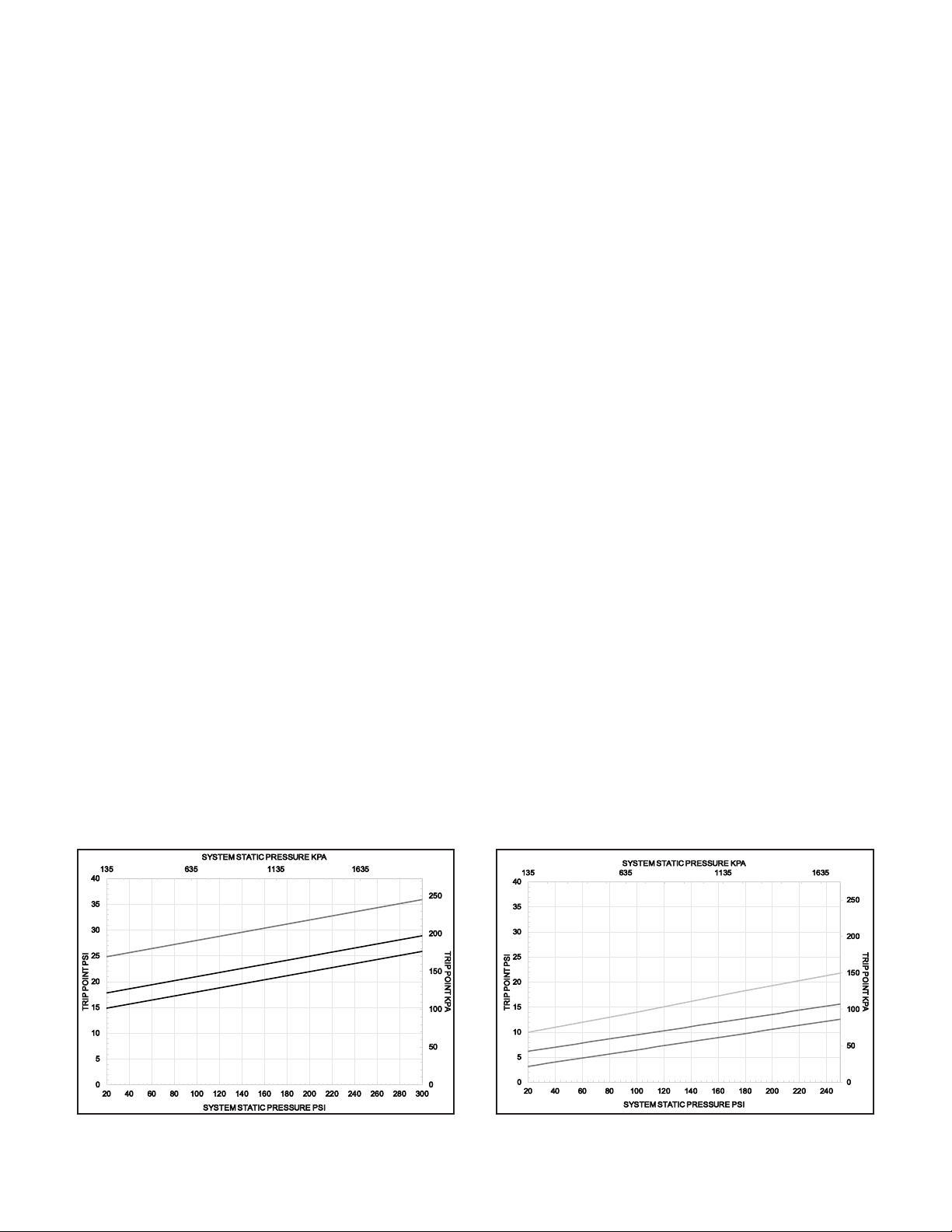
See recommended system air/nitrogen pressure and expected trip range below
for the Model GDPA. More detailed information can be found about the Dry
Pilot Actuator in Technical Data Sheet GFV550.
GDPA VS GDPA-LP
When choosing the dry pilot actuator for your system
there are many factors which inuence the uid delivery time. These factors range from system geometry,
riser location, sprinkler orice size, supply pressure,
pump ramping time and more. In certain systems,
higher system air pressure can be advantageous over
lower system air pressure and the opposite can also
be true. Some things to consider when choosing the
GDPA vs the GDPA-LP are discussed below.
The initial air pressure in a system may vary. For example in one system the initial air pressure may be set
for 15 psi (1 Bar) and 45 psi (3.1 Bar) for the other. The
system air pressure will decay at a faster rate with the
higher initial system pressure. For a xed pressure
drop (i.e. 5 psi drop) will be reached more quickly with
the higher initial air pressure than lower initial air pressure.
Unfortunately uid delivery time is not just dependent
on tripping the control valve but also dependent on
the uid moving through the system. As the water lls
the system piping it can create a high pressure pocket
of air at the inspectors test connection. This higher
air pressure can slow the progress of the water progressing towards the inspectors test connection. This
phenomenon typically happens with smaller K-factor
sprinklers. This scenario may lend itself to choosing
to utilize lower system air pressure and the GDPA-LP
actuator.
In other circumstances, systems are center fed, mean-
ing roughly half of the volume of piping is on one side
of the riser and half on the other. In these scenarios,
higher system air pressure can be benecial to system
delivery time as the higher air pressure will actually impede or stop the propagation of water in the direction
opposite the inspectors test connection (ITC) and force
the majority of the available water ow towards the ITC.
It would be impossible to run through every scenario
possible but there are a few generalities which can
be used as guidance. Generally end fed systems will
achieve faster uid delivery times with lower air pressure. Generally center fed systems with moderate to
better than moderate water supplies will have faster
Recommended Air/Nitrogen Pressure
GDPA Trip Range
Recommended Air/Nitrogen Pressure
GDPA-LP Trip Range
FIGURE 1:MODEL GDPA DRY PILOT
TRIP RANGE
MAR 2018 GFV-305 (Formerly H-3) Page 2 of 11
FIGURE 2:MODEL GDPA-LP DRY
PILOT TRIP RANGE
Page 3
uid delivery times with higher air pressure. This is
meant to be general guidance, and should be in no
way taken as a guarantee of uid delivery time. All
systems and congurations are different and there are
always exceptions to the rule.
GDPA-LP
The Model GDPA-LP is only recommended for system
supply pressures up to 250 psi (17.2 Bar). The GDPA-
LP is factory painted green to identify the low pressure
version. The Model GDPA is the standard pressure actuator, while the GDPA-LP can be utilized for low system air pressures. The types of systems where the
use of the GDPA-LP has the potential to be benecial
to system performance are: Dry Systems, and Double
Interlock Electric/Pneumatic Systems. There is little to
no advantage to utilizing the GDPA-LP in Single Interlock Dry Pilot, or Deluge Dry Pilot Systems, as the pilot
lines generally have a very small volume and the valve
trips very quickly no matter the pilot line pressure.
If you have any questions on the application of the
GDPA vs the GDPA-LP contact Globe Sprinkler Technical Services.
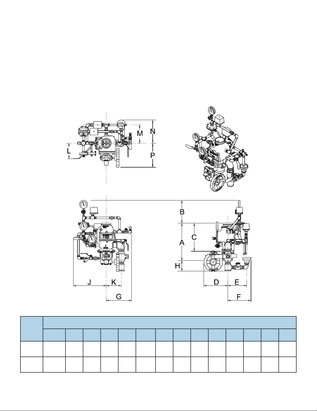
Valve
Size
A
END TO END
TOP VIEW
FRONT VIEW RIGHT SIDE
Nominal Installation Dimensions Inches (mm)
B C D E F G H J K L M N P
4"
(DN100)
6"
(DN150)
17.6
(447.7)
19.75
(501.6)
11
(279)
10
(254)
13.25
(336.5)
14.5
(368.3)
12
(304)
13
(330)
9.0
(228.6)
9.0
(228.6)
11.0
(279.4)
12
(304)
12.0
(304.8)5 (127)
13
(330)
4.4
(111 )
16
(406)
16
(406)
7.125
(181)
8.5
(216)
8
(203)
8
(203)
8.625
(219)
9.75
(247.6)
11.0
(279.4)
11.0
(279.4)
12
(304)
13
(330)
FIGURE 3:DRY ACTUATION TRIM DIMENSIONS
MAR 2018 GFV-305 (Formerly H-3) Page 3 of 11
Page 4
2 1
SYSTEM PIPING WITH AUTOMATIC SPRINKLERS
2 1
LOW AIR PRESSURE
SYSTEM
ALARM SWITCH
PRESSURE
GAUGE
DRY PILOT
DRAIN
ACTUATOR
MANUAL CONTROL/
EMERGENCY
RELEASE STATION
(NORMALLY
CLOSED)
MAIN DRAIN VALVE
(NORMALLY CLOSED)
PRESSURE CHAMBER
SUPPLY CONTROL VALVE
(NORMALLY OPEN)
PRESSURE
CHAMBER
RESTRICTION
GAUGE
MAIN
CONTROL VALVE
(NORMALLY OPEN)
WATER
SUPPLY
AIR SUPPLY
CONTOL VALVE
(NORMALLY OPEN)
WATERFLOW
ALARM SWITCH
ALARM TEST VALVE
(NORMALLY CLOSED)
WATER
SUPPLY
PRESSURE
GAUGE
AUTOMATIC
AIR/NITROGEN
MAINTENANCE
DEVICE
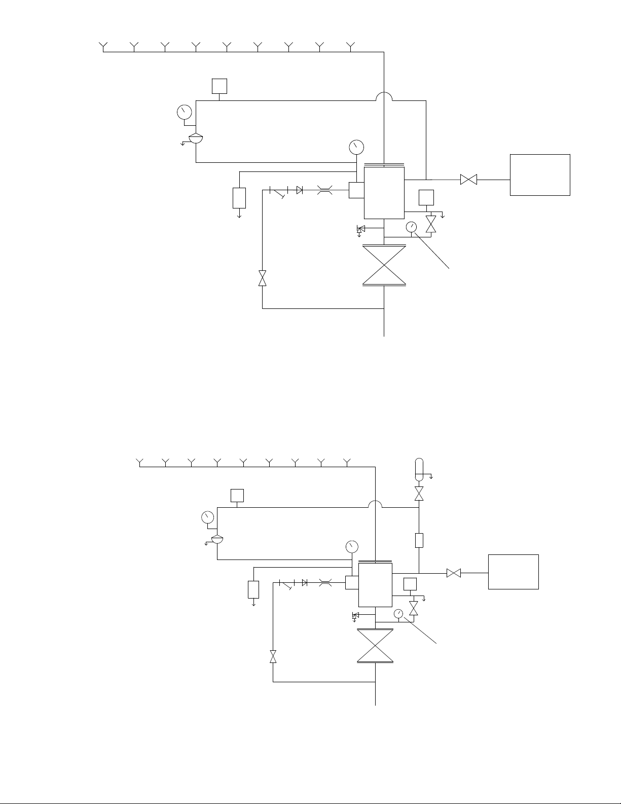
FIGURE 4:DRY SCHEMATIC (NO ACCELERATOR)
SYSTEM PIPING WITH AUTOMATIC SPRINKLERS
LOW AIR PRESSURE
DRY PILOT
ACTUATOR
ALARM SWITCH
PRESSURE
CHAMBER
GAUGE
RESTRICTION
MAIN DRAIN VALVE
(NORMALLY CLOSED)
SYSTEM
PRESSURE
GAUGE
DRAIN
MANUAL CONTROL/
EMERGENCY
RELEASE STATION
(NORMALLY
CLOSED)
PRESSURE CHAMBER
SUPPLY CONTROL VALVE
(NORMALLY OPEN)
ACCELERATOR
ATMOSPHERE
ACCELERATOR
ISOLATION VALVE
(NORMALLY OPEN)
ANTIFLOOD
DEVICE
CONTOL VALVE
(NORMALLY OPEN)
WATERFLOW
ALARM SWITCH
ALARM TEST VALVE
(NORMALLY CLOSED)
MAIN
CONTROL VALVE
(NORMALLY OPEN)
MODEL C
TO
AIR SUPPLY
AUTOMATIC
AIR/NITROGEN
MAINTENANCE
DEVICE
WATER
SUPPLY
PRESSURE
GAUGE
WATER
SUPPLY
FIGURE 5:DRY SCHEMATIC WITH ACCELERATOR
MAR 2018 GFV-305 (Formerly H-3) Page 4 of 11
Page 5

FIGURE 6: 4" RCW DRY TRIM ARRANGEMENT
13
21
4
16
14
5
38
21
7
83
24
47
• NOTE: PREASSEMBLED TRIM WITH BUTTERFLY VALVE SHOWN.
FOR PREASSEMBLED WITHOUT BUTTERFLY VALVE AND NONASSEMBLED TRIM CONFIGURATION, ENSURE PRESSURE CHAMBER
SUPPLY IS CONNECTED FROM BELOW CONTROL VALVE.
TO DRIP
28
56
54
3
17
16
14
26
43
CUP
13
27
15
43
55
25
26
47
TO DRIP
CUP
4
3
20
35
12
41
20
20
4
3
4
45
46
57
44
33
32
11
11
31
29
18
81
20
80
21
22
40
11
A
1
49
23
19
TO DRIP
CUP
8
11
39
REMOVE ITEM 81
IF UTILIZING OPTIONAL
81
4
72
46
50
ACCELERATOR TRIM
47
47
52
4
57
2
50
51
47
B
42
6
79
41
62
TO AIR MAINTENANCE DEVICE
35
47
3
7
34
66
9
52
48
ITEM NO. PART NO. DESCRIPTION QTY. ITEM NO. PART NO. DESCRIPTION QTY.
1 310802-G 2" x 3" GALV. NIPPLE 1 33 311224-G 3/4" x 1/2" GALV. STREET ELBOW 1
2 311208-G 2" GALV. ELBOW 1 34 311801 1" CHECK VALVE (FxF) 1
3 310306-G 1/2" x 4" GALV. NIPPLE 4 35 311314-G 1/2" x 1/2" x 1/4" GALV. TEE 2
4 310301-G 1/2" x 1 1/2" GALV. NIPPLE 6 38 317395 1/2" RESTRICTOR 1
5 310305-G 1/2" x 3 1/2" GALV. NIPPLE 1 39 311404-G 3/4" GALV. UNION 1
6 323300 VELOCITY CHECK VALVE 1 40 310401-G 3/4" x 2" GALV. NIPPLE 1
7 311696-R 1/2" BALL VALVE (MxF) - RED HANDLE 2 41 311794-GR 1/2" BALL VALVE (MxM) - GREEN HANDLE 2
8 311313-G 3/4" x 1/2" x 3/4" GALV. TEE 1 42 310308-G 1/2" x 5" GALV. NIPPLE 1
9 317398 DRIP CUP ASSEMBLY 1 43 311683 1/4" 3-WAY VALVE 2
11 310413-G 3/4" x 1 1/2" GALV. NIPPLE 4 44 1340104 PS-10-2 ALARM SWITCH 1
12 310105-G 1/4" x 3 1/2" GALV. NIPPLE 1 45 1340404 PS-40-2 ALARM SWITCH 1
13 311001-G 1/4" GALV. PLUG 2 46 310304-G 1/2" x 3" GALV. NIPPLE 2
14 300119-D 3 1/2" WATER GAUGE (300PSI) 2 47 311203-G 1/2" GALV. ELBOW 6
15 300120-D 3 1/2" AIR GAUGE (250PSI) 1 48 311207-G 1" GALV. STREET ELBOW 1
16 311210-G 1/2" GALV. STREET ELBOW 2 49 311799-R 2" BALL VALVE (FxF) - RED HANDLE 1
17 300111-G 1/2" GALV. CROSS 1 50 310800-G 2" CLOSE GALV. NIPPLE 2
18 311004-G 3/4" GALV. PLUG 1 51 311338-G 2" x 2" x 1" GALV. TEE 1
19 311786 3/4" CHECK VALVE (MxF) 1 52 310501-G 1" x 2" GALV. NIPPLE 2
20 311403-G 1/2" GALV. UNION 4 54 310302-G 1/2" x 2" GALV. NIPPLE 1
21 311305-G 1/2" x 1/4" x 1/2" GALV. TEE 3 55 310101-G 1/4" x 1 1/2" GALV. NIPPLE 1
22 310161 1/4" TUBE CONNECTOR 1 56 317554 DRY PILOT ACTUATOR 1
23 M-320604 1/4" COPPER TUBE - 57 311303-G 1/2" GALV. TEE 2
24 310346 1/2" ELBOW TUBE CONNECTOR 1 62 317445
1/4" PRESSURE RELIEF VALVE (ADJ. PSI)
FACTORY SET @ 45PSI
1
25 310164 1/2" TUBE CONNECTOR 1 66 310310-G 1/2" x 6" GALV. NIPPLE 1
26 M-320591 1/2" COPPER TUBE - 72 311802 1/2" CHECK VALVE (MxF) 1
27 317397 1/2" Y-STRAINER 1 79 310110-G 1/4" x 6" GALV. NIPPLE 1
28 317396 1/2" SPRING LOADED CHECK VALVE 1 80 310303-G 1/2" x 2 1/2" GALV. NIPPLE 1
29 311794-R 1/2" BALL VALVE (MxM) - RED HANDLE 1 81 310313-G 1/2" x 7 1/2" GALV. NIPPLE 2
31 300112-G 3/4" GALV. CROSS 1 83 310337-G 1/2" x 9 1/2" GALV. NIPPLE 1
32 311212-G 3/4" x 1/2" GALV. REDUCING ELBOW 1
MAR 2018 GFV-305 (Formerly H-3) Page 5 of 11
Page 6

FIGURE 7: 6" RCW DRY TRIM ARRANGEMENT
13
43
55
21
4
56
16
54
14
38
21
82
24
47
• NOTE: PREASSEMBLED TRIM WITH BUTTERFLY VALVE SHOWN.
FOR PREASSEMBLED WITHOUT BUTTERFLY VALVE AND NONASSEMBLED TRIM CONFIGURATION, ENSURE PRESSURE CHAMBER
SUPPLY IS CONNECTED FROM BELOW CONTROL VALVE.
17
5
7
26
TO DRIP
CUP
43
28
13
27
41
47
5
4
16
12
20
15
25
TO DRIP
35
CUP
44
46
57
26
32
68
29
20
42
20
414
5
54
81
20
80
33
11
31
44
21
22
23
40
TO DRIP
19
CUP
8
18
11
39
11
4
4
57
A
46
1
51
42
72
47
47
2
50
49
50
47
B
64
REMOVE ITEM 64
IF UTILIZING OPTIONAL
ACCELERATOR TRIM
6
79
41
7
3
52
34
52
62
TO AIR MAINTENANCE DEVICE
35
47
66
9
48
ITEM NO. PART NO. DESCRIPTION QTY. ITEM NO. PART NO. DESCRIPTION QTY.
1 310802-G 2" x 3" GALV. NIPPLE 1 33 311224-G 3/4" x 1/2" GALV. STREET ELBOW 1
2 311208-G 2" 90° GALV. ELBOW 1 34 311801 1" CHECK VALVE (FxF) 1
3 310306-G 1/2" x 4" GALV. NIPPLE 1 35 311314-G 1/2" x 1/2" x 1/4" GALV. TEE 2
4 310301-G 1/2" x 1 1/2" GALV. NIPPLE 5 38 317395 1/2" RESTRICTOR 1
5 310305-G 1/2" x 3 1/2" GALV. NIPPLE 3 39 311404-G 3/4" GALV. UNION 1
6 323300 VELOCITY CHECK VALVE 1 40 310401-G 3/4" x 2" GALV. NIPPLE 1
7 311696-R 1/2" BALL VALVE MXF - RED HANDLE 2 41 311794-GR 1/2" BALL VALVE MxM - GREEN HANDLE 2
8 311313-G 3/4" x 1/2" x 3/4" GALV. TEE 1 42 310308-G 1/2" x 5" GALV. NIPPLE 2
9 317398 DRIP CUP ASSEMBLY 1 43 311683 1/4" 3-WAY VALVE 2
11 310413-G 3/4" x 1 1/2" GALV. NIPPLE 3 44 1340104 PS-10-2 ALARM SWITCH 1
12 310105-G 1/4" x 3 1/2" GALV. NIPPLE 1 45 1340404 PS-40-2 ALARM SWITCH 1
13 311001-G 1/4" GALV. PLUG 2 46 310304-G 1/2" x 3" GALV. NIPPLE 2
14 300119-D 3-1/2" WATER GAUGE (300PSI) 2 47 311203-G 1/2" GALV. ELBOW 5
15 300120-D 3-1/2" AIR GAUGE (250PSI) 1 48 311207-G 1" GALV. STREET ELBOW 1
16 311210-G 1/2" GALV. STREET ELBOW 4 49 311799-R 2" BALL VALVE (FxF) - RED HANDLE 1
17 300111-G 1/2" GALV. CROSS 1 50 310800-G 2" CLOSE GALV. NIPPLE 2
18 311004-G 3/4" GALV. PLUG 1 51 311338-G 2" x 2" x 1" GALV. TEE 1
19 311786 3/4" CHECK VALVE MxF 1 52 310501-G 1" x 2" GALV. NIPPLE 2
20 311403-G 1/2" GALV. UNION 4 54 310302-G 1/2" x 2" GALV. NIPPLE 1
21 311305-G 1/2" x 1/4" x 1/2" GALV. TEE 3 55 310101-G 1/4" x 1 1/2" GALV. NIPPLE 1
22 310161 1/4" TUBE CONNECTOR 1 56 317554 DRY PILOT ACTUATOR 1
23 M-320604 1/4" COPPER TUBE - 57 311303-G 1/2" GALV. TEE 2
24 310346 1/2" ELBOW TUBE CONNECTOR 1 62 317445
1/4" PRESSURE RELIEF VALVE (ADJ. PSI) FAC-
TORY SET @ 45PSI
1
25 310164 1/2" TUBE CONNECTOR 1 66 310310-G 1/2" x 6" GALV. NIPPLE 1
26 M-320591 1/2" COPPER TUBE -
27 317397 1/2" Y-STRAINER 1
28 317396 1/2" SPRING LOADED CHECK VALVE 1
29 311794-R 1/2" BALL VALVE MxM - RED HANDLE 1
31 300112-G 3/4" GALV. CROSS 1
32 311212-G 3/4" x 1/2" GALV. REDUCING ELBOW 1
68 310402-G 3/4" x 2 1/2" GALV. NIPPLE 1
64 310336-G 1/2" x 7" GALV. NIPPLE 1
72 311802 1/2" CHECK VALVE MxF 1
79 310110-G 1/4" x 6" GALV. NIPPLE 1
80 310303-G 1/2" x 2 1/2" GALV. NIPPLE 1
81 310313-G 1/2" x 7 1/2" GALV. NIPPLE 1
MAR 2018 GFV-305 (Formerly H-3) Page 6 of 11
Page 7

FIGURE 8: OPTIONAL ACCELERATOR TRIM ARRANGEMENT
4" ACCELERATOR TRIM ARRANGEMENT
A
A
ITEM
15
70
55
54
B
63
59
27
59
41
57
46
20
65
• NOTE: FITTINGS LABELED
A AND B ARE INCLUDED ON
DRY TRIM, TIE IN ACCEL-
ERATOR TRIM AT THESE
LOCATIONS
58
NO.
15 300120-D 3 1/2" AIR GAUGE (250PSI) 1
20 311403-G 1/2" GALV. UNION 1
27 317397 1/2" Y-STRAINER 1
41 311794-R "1/2"" BALL VALVE MxM - RED 1
46 310304-G 1/2" x 3" GALV. NIPPLE 1
54 310302-G 1/2" x 2" GALV. NIPPLE 1
55 310101-G 1/4" x 1 1/2" GALV. NIPPLE 1
57 311303-G 1/2" GALV. TEE 1
58 300400 GLOBE MODEL "C" ACCELERATOR 1
59 310300-G 1/2" CLOSE GALV. NIPPLE 2
63 323340 MODEL "D" ANTI-FLOODING DEVICE 1
65 320506 ø.125 RESTRICTED ORIFICE 1
70 311213-G 1/2" x 1/4" GALV. ELBOW 1
PART
NO.
DESCRIPTION QTY.
6" ACCELERATOR TRIM ARRANGEMENT
ITEM
15
70
55
59
B
63
54
27
59
41
57
59
20
65
• NOTE: FITTINGS LABELED
A AND B ARE INCLUDED ON
DRY TRIM, TIE IN ACCEL-
ERATOR TRIM AT THESE
LOCATIONS
58
NO.
15 300120-D 3 1/2" AIR GAUGE (250PSI) 1
20 311403-G 1/2" GALV. UNION 1
27 317397 1/2" Y-STRAINER 1
41 311794-R 1/2" BALL VALVE MxM - RED 1
54 310302-G 1/2" x 2" GALV. NIPPLE 1
55 310101-G 1/4" x 1 1/2" GALV. NIPPLE 1
57 311303-G 1/2" GALV. TEE 1
58 300400 GLOBE MODEL "C" ACCELERATOR 1
59 310300-G 1/2" CLOSE GALV. NIPPLE 3
63 323340 MODEL "D" ANTI-FLOODING DEVICE 1
65 320506 ø.125 RESTRICTED ORIFICE 1
70 311213-G 1/2" x 1/4" GALV. ELBOW 1
PART
NO.
DESCRIPTION QTY.
ACCELERATOR TRIM
The accelerator trim comes in three different options. If the
valve is ordered pre-assembled the appropriate trim con-
guration will be added to the dry valve trim according to
Figure 4 or Figure 5 respectively. If the accelerator trim is
ordered as a separate trim kit, the kit will include all of the
necessary parts and pieces to construct either the 4" or 6"
arrangement. Therefore there is only one part number for
the 4" and 6" accelerator assembly trim kit.
MAR 2018 GFV-305 (Formerly H-3) Page 7 of 11
The dry system trim is approved with the Model C mechanical accelerator. See Technical Datasheet H-8 for more
information on the antiood device and mechanical accelerator.
Page 8

INSTALLATION AND MAINTENANCE
INSTALLATION
Proper operation of the RCW Valve (i.e., opening of the
RCW Valve as during a re condition) is highly dependent
on the correct installation of the trim. It is necessary to in-
stall the trim components as described in the gures above
for the valve to function properly. Failure to do so may
prevent the valve from functioning and could void Listings,
Approvals, and/or the manufacturer's warranty. All tubing
directed to the "drip cup" must have smooth bends. Abrupt
changes in direction or kinks in the tubing could result in a
restriction of ow and an adverse effect on the functionality
of the valve.
The Model RCW Valve must be installed in an accessible
and visible location, which is maintained at or above a minimum temperature of 40ºF (4ºC). The RCW Valve must be
installed in the vertical orientation.
All valves must be installed in accordance with the appropriate installation standard (i.e. NFPA 13, NFPA 15 or other).
All electrical connections must be made per the applicable
installation standard and/or the National Electric Code (i.e.
NFPA 70, NFPA 72 or other).
Proper hydrostatic test procedure must be followed per
NFPA 13. The velocity check valve must be replaced with a
plug temporarily, the pressure chamber must be vented during the hydrostatic test procedure by opening the manual
release valve and the clapper must be latched in the open
position.
DRY VALVE SETTING
PROCEDURE
The following steps are to be followed for initial setting
of the Model RCW dry system valve, after a trip test of
the re protection system or, after any system operation.
STEP 1. Close the main control valve.
STEP 2. Close the pressure chamber supply control
valve and the system air supply valve.
STEP 3. Open the main drain valve, lower body (Aux)
drain valve, all low point drain valves and auxiliary drain valves on the system. Open the manual emergency release control valve. Depress
the plunger of the velocity check valve to verify
that it is not under pressure and that the system piping is completely drained. After system
is completely drained, close all low point and
auxiliary drain valves that are open. The manual emergency release control valve and main
drain valve should remain open until directed in
the following steps.
STEP 4. Depress the reset plunger located at the top of
the pressure chamber to reset the clapper of
the RCW valve (the sound of the clapper falling into position should be heard). Close the
manual emergency release control valve.
STEP 5. Replace any operated automatic sprinklers
with the same type, i.e. orientation, orice, temperature, and thermal sensitivity. Open the
air supply valve to re-establish normal system
pressure. Open the manual emergency release
control valve and then the pressure chamber
supply control valve. Slowly close the manual
emergency release control valve and allow
pressure to increase in the pressure chamber
and also up to the dry pilot actuator.
MAR 2018 GFV-305 (Formerly H-3) Page 8 of 11
STEP 6. Observe all drain tubing at the drip cup. If any
leakage is observed, the source of the leakage
must be identied and corrected.
STEP 7. Partially open the main control valve. Slowly
close the main drain valve when water discharges from the drain connection. Observe
the supply pressure gauge and the pressure
chamber gauge. They should indicate the same
pressure reading. Depress the plunger on the
velocity check valve. If leakage is apparent, the
cause of the leakage must be identied and
corrected. If there are no leaks, open the system control valve fully and the system is set for
service.
MODEL C ACCELERATOR
SETTING PROCEDURE
STEP 1. Close the accelerator shutoff valve
STEP 2. Follow the Dry Valve Setting Procedure
STEP 3. Upon completion of the Dry Valve Setting Pro-
cedure. Open the accelerator shutoff valve
slowly. Watch the pressure gauge on the upper
chamber of the Model C Accelerator for 30 seconds. The pressure should start to increase. If
the pressure increases and the accelerator sets
(no air coming from the discharge of the accelerator), wait for the upper chamber of the accelerator to reach the system air pressure and the
system is set for service. If the pressure does
not increase in 30 seconds continue to step 4.
STEP 4. Close the accelerator shutoff valve. Remove
the lower hand wheel plug. The accelerator interior valve assembly should be removed. This
complete assembly can be pulled out by hand
(if it does not come out with the lower hand
wheel plug when it is unscrewed). This will
allow any water, that may have accumulated
in the upper chamber, to drain out and permit
thorough cleaning of the valve disc, seat as-
sembly, and the orice pin.
STEP 5. The valve assembly can then be replaced and
the lower hand wheel plug screwed back into
position. Open the accelerator shutoff valve
slowly. The accelerator is set for service when
the air pressure gauge on the top of the accelerator reads normal system air pressure. If air
pressure does not rise in the upper chamber of
the accelerator after 1 minute call Globe Technical Support for more detailed instruction.
TESTING
Reference NFPA 25, Standard for the Inspection, Testing
and Maintenance of Water-Based Fire Protection Systems.
Before proceeding with any tests involving water ow, the
following precautions need to be taken:
STEP 1. Check the location where the test connection
discharges to make sure that all is clear and
that there is no possibility of the water ow
causing damage or injury.
STEP 2. Check the end of the test connection to make
sure that it is unobstructed. To achieve a satis-
factory test, there must be an unrestricted ow
of water when the test valve is wide open.
STEP 3. Check for alarm connections to a central sta-
Page 9

tion or re department. If such connections are
found, give proper notice to the signal receiving
station before proceeding with the test.
Note: A main drain test may also operate local re alarms unless they are tem-
porarily disabled.
DRY SYSTEM TRIP TEST
PROCEDURE
Proper operation of the RCW Valve (i.e., opening of the
RCW Valve as during a re condition) must be veried, as
described by the applicable Inspection Testing and Main-
tenance Standard (i.e. NFPA 25) or by the Local Authority
Having Jurisdiction. Globe Sprinkler Corporation recom-
mends performing a trip test annually. The steps to perform
a trip test are as follows:
STEP 1. If a partial ow trip test is necessary, perform
the following additional steps. If a normal ow
test is being performed continue to Step 2:
1. Close the main control valve.
2. Open the main drain valve.
3. Open the main control valve one turn beyond the position
at which water just begins to ow from the main drain valve.
4. Close the main drain valve.
Note: Be sure to close the main control valve quickly after the trip of the valve has
been veried.
STEP 2. Open the inspectors test valve at the end of the
system.
STEP 3. Verify that the RCW Valve has tripped, as indi-
cated by the ow of water into the system and
activation of the water ow alarm.
STEP 4. Close the system’s Main Control Valve.
STEP 5. Close the Diaphragm Chamber Supply Control
Valve.
STEP 6. Reset the RCW Dry Valve in accordance with
the Dry Valve Setting Procedure.
• Where difculty in performance is experienced, the
Clapper Facing. The rubber clapper facing should be
checked for wear or damage to determine that it is free of
dirt and other foreign substances. If found to be worn or
damaged (e.g., foreign matter embedded in the surface),
the facing should be replaced. If it is dirty, it should be
cleaned. Compounds which could damage the rubber facing must never be used.
Seat Ring. The seat ring should be checked for nicks and
for stones, dirt or other foreign matter lodged in the grooves
or holes. It should be cleaned thoroughly. If the seat ring is
found to be damaged, valve should be replaced.
Alarm Line Check Valve. The ¾” check valve connected
to the intermediate chamber should be checked for clapper
and seat condition.
RCW Valve. Main Drain Valve and all controlling valves
which are normally closed when the deluge valve is in the
set position should be checked to be sure that they are fully
closed and not leaking.
manufacturer or its authorized representative shall
be contacted before any eld adjustment is to be
made.
DRY SYSTEM WATERFLOW
ALARM TEST PROCEDURE
Testing of the system water ow alarms must be performed as
described by the applicable inspection testing and maintenance
standard (i.e. NFPA 25) or as described by the local AHJ. To
test the water ow alarm, open the alarm test valve, which will
allow a ow of water to the pressure alarm switch and/or water
motor alarm. Upon satisfactory completion of the test, close the
alarm test valve.
MAINTENANCE
Note:
• All valves should be carefully inspected, tested, and
maintained in accordance with NFPA 25 or other
applicable Standard.
• It is important to ensure a clean water supply free
of debris and solid particles such as sand, gravel,
or mud.
• If, during an inspection of a water control valve,
sediment or free particles of matter are noted,
a further examination of internal valve parts is
necessary.
• All deposits should be removed from all operating
parts and ports. Vent holes through intermediate
chamber should be thoroughly cleaned and ushed
with clean water.
MAR 2018 GFV-305 (Formerly H-3) Page 9 of 11
Page 10

ORDERING INFORMATION
The RCW Valve, Dry System conguration or Dry System
with accelerator conguration can be ordered pre-trimmed
or non-assembled as separate items. All trim comes
standard with galvanized nipples and ttings (Standard
galvanized trim is not domestic). For non-assembled the
following items must be ordered separately:
• RCW Water Control Valve
• Dry System Trim Kit
• Optional Accelerator Trim Kit
• Automatic Air Supply (Air Maintenance Device)
• Accessories (as needed)
PRE-TRIMMED WITH MODEL
GLR300G CONTROL VALVE
RCW Dry Pre-Trimmed (No Accelerator)
Specify: RCW Dry Pre-trimmed w/BFV Control
Valve (specify valve size),
4 inch GxG. . . . . . . . . . . . . . . . . . . . . . . . 317448-B
4 inch GxG. . . . . . . . . . . . . . . . . . . . . . . . 317448-B-LP
6 inch GxG. . . . . . . . . . . . . . . . . . . . . . . . 317493-B
6 inch GxG. . . . . . . . . . . . . . . . . . . . . . . . 317493-B-LP
DN 150 (165,1 mm) GXG ............317493-D-B
DN 150 (165,1 mm) GXG ............317493-D-B-LP
RCW Dry Pre-Trimmed with Accelerator
Specify: RCW Dry Pre-trimmed (specify valve
size), PN (see Part Number Below)
4 inch GxG. . . . . . . . . . . . . . . . . . . . . . . . 317449-B
4 inch GxG. . . . . . . . . . . . . . . . . . . . . . . . 317449-B-LP
6 inch GxG. . . . . . . . . . . . . . . . . . . . . . . . 317494-B
6 inch GxG. . . . . . . . . . . . . . . . . . . . . . . . 317494-B-LP
DN 150 (165,1 mm) GXG ............317494-D-B
DN 150 (165,1 mm) GXG ............317494-D-B-LP
Note:
-LP denotes version with GDPA-LP actuator (Lower System Pressure)
PRE-TRIMMED WITHOUT BFV
CONTROL VALVE
RCW Dry Pre-Trimmed (No Accelerator)
Specify: RCW Dry Pre-trimmed (specify valve
size)
4 inch GxG. . . . . . . . . . . . . . . . . . . . . . . . 317448
4 inch GxG. . . . . . . . . . . . . . . . . . . . . . . . 317448-LP
6 inch GxG. . . . . . . . . . . . . . . . . . . . . . . . 317493
6 inch GxG. . . . . . . . . . . . . . . . . . . . . . . . 317493-LP
DN 150 (165,1 mm) GXG. ............317493-D
DN 150 (165,1 mm) GXG. ............317493-D-LP
6 inch GxG. . . . . . . . . . . . . . . . . . . . . . . . 317494
6 inch GxG. . . . . . . . . . . . . . . . . . . . . . . . 317494-LP
DN 150 (165,1 mm) GXG ............317494-D
DN 150 (165,1 mm) GXG ............317494-D-LP
Note:
-LP denotes version with GDPA-LP actuator (Lower System Pressure)
NON-ASSEMBLED
• Valve body ordered separately
• Accelerator Trim Kit ordered separately
• Trim Kit includes extra pieces to accommodate different
size valves
RCW Water Control Valve
Specify: RCW Valve Only (specify valve size),
4 inch RCW-2 GxG .................317400
6 inch RCW-2 GxG .................317550
DN 150 (165,1 mm) RCW-2 GXG. .....317550-D
RCW Dry Trim 4 inch or 6 inch or DN 150
Specify: RCW Dry Trim Kit,
Dry Trim Kit .......................317340
Dry Trim Kit .......................317340-LP
Note:
-LP denotes version with GDPA-LP actuator (Lower System Pressure)
Model C Accelerator Trim Kit 4 inch or 6 inch
Specify: RCW Dry Model C Accelerator Trim Kit,
PN ..............................317341
Note:
Trim Kit includes extra pieces to accommodate different size valves
See Technical Data Sheet H-8 for more information on the Model C Accelera-
tor and Antiood Device
Model H-1, H-2 or H-3 Air Maintenance Device
Specify: Model (Specify Model) Air Maintenance Device
(see Part Number below)
H-1 ..............................320585
H-2 ..............................320595
H-3 ..............................320600
See Technical Literature G-1 and G-2 for more information
on Air Maintenance Devices
Note:
300 psi (20.6 Bars) Pressure Gauges Standard (600 psi (41.2 Bars) Ordered
Separately
PN ........................................300121-D
See trim drawings for trim replacement part numbers
See Technical Data Sheet GFV200 for RCW Valve replacement part numbers
RCW Dry Pre-Trimmed with Accelerator
Specify: RCW Dry Pre-trimmed (specify valve
size), PN (see Part Number Below)
4 inch GxG. .......................317449
4 inch GxG. .......................317449-LP
MAR 2018 GFV-305 (Formerly H-3) Page 10 of 11
Page 11

GLOBE® PRODUCT
WARRANTY
Globe agrees to repair or replace any of its own manufactured products found to be defective in material or workmanship for a period of one year from date of shipment.
For specic details of our warranty please refer to Price
List Terms and Conditions of Sale (Our Price List).
4077 Airpark Dr.
Standish, MI 48658
Ph. 989-846-4583
MAR 2018 GFV-305 (Formerly H-3) Page 11 of 11
techservice@globesprinkler.com
Technical Support
1-800-248-0278
www.globesprinkler.com
 Loading...