

Page 1
Model #:
Serial #:
Model GFP500
Instruction Manual for
Globe Vegetable Cutter Models
GFP500, GFP550, GFP700, and GFP750
For Service on Your Vegetable Cutter
1. Visit our website at www.globeslicers.com (select Service button)
2. Or...Call Globe service department at 937-297-7247 and ask for the contact
information for your local service company
Visit our website for information on additional products available from Globe.
Slicers, Mixers, Vegetable Cutters, Meat Choppers, and Scales
This manual contains important safety instructions which
must be strictly followed when using this equipment.
www.globeslicers.com
- IMPORTANT SAFETY NOTICE -
Page 2

Index
ATTENTION OWNERS AND OPERATORS................................................................................................. 3
KEY COMPONENTS OF THE VEGETABLE CUTTER ................................................................................ 4
INST ALLA TION AND PROPER GROUNDING............................................................................................. 5-6
OPERATING INSTRUCTIONS..................................................................................................................... 7-8
DISC INSTALLATION AND REMOVAL ........................................................................................................ 9-11
CLEANING................................................................................................................................................... 12-13
DISCS AND ACCESSORIES AVAILABLE.................................................................................................... 14-15
LIMITED WARRANTY.................................................................................................................................. 16
© Globe Food Equipment Company, 2006
Printed in USA
GLOBE FOOD EQUIPMENT COMPANY
P.O. BOX 3209
DAYTON, OH 45401
PHONE: 937-299-5493
FAX: 937-299-4147
E-MAIL: globeinfo@globeslicers.com
WEBSITE: www.globeslicers.com
Page 2
Page 3

Attention Owners and Operators
Globe’s equipment is designed to provide safe and productive processing of food products as long as the
equipment is used in accordance with the instructions in this manual and is properly maintained. Importantly,
unless the operator is adequately trained and supervised there is a possibility of serious injury. Owners of this
equipment bear the responsibility to make certain that this equipment is used properly and safely. Strictly following
all the instructions contained in this manual and the requirements of local, state or federal law.
Owners should not permit anyone to touch this equipment unless they are over 18 years old, are adequately
trained and supervised, and have read and understood this manual. Owners should also ensure that no
customers, visitors or other unauthorized personnel come in contact with this equipment. Please remember that
Globe cannot anticipate every circumstance or environment in which its equipment will be operated. It is the
responsibility of the owner and the operator to remain alert to any hazards posed by the function of this equipment,
particularly the sharp blade on each cutting disc and all moving parts. If you are ever uncertain about a particular
task or the proper method of operating this equipment, ask your supervisor.
Throughout the manual you will see additional warnings to help alert you to potential hazards.
Warnings affecting your personal safety are indicated by:
or
Warnings related to possible damage to the equipment are indicated by:
Make certain that this manual is available for easy reference by any operator. Globe has put a warning label on its
vegetable cutters. If the warning label or this manual are misplaced, damaged, or illegible, or if you require
additional copies, please contact your nearest representative or Globe directly for these items at no charge.
Please remember that this manual and the warning label do not replace the need to be alert, properly train and
supervise operators, and use common sense when using this equipment.
Page 3
Page 4
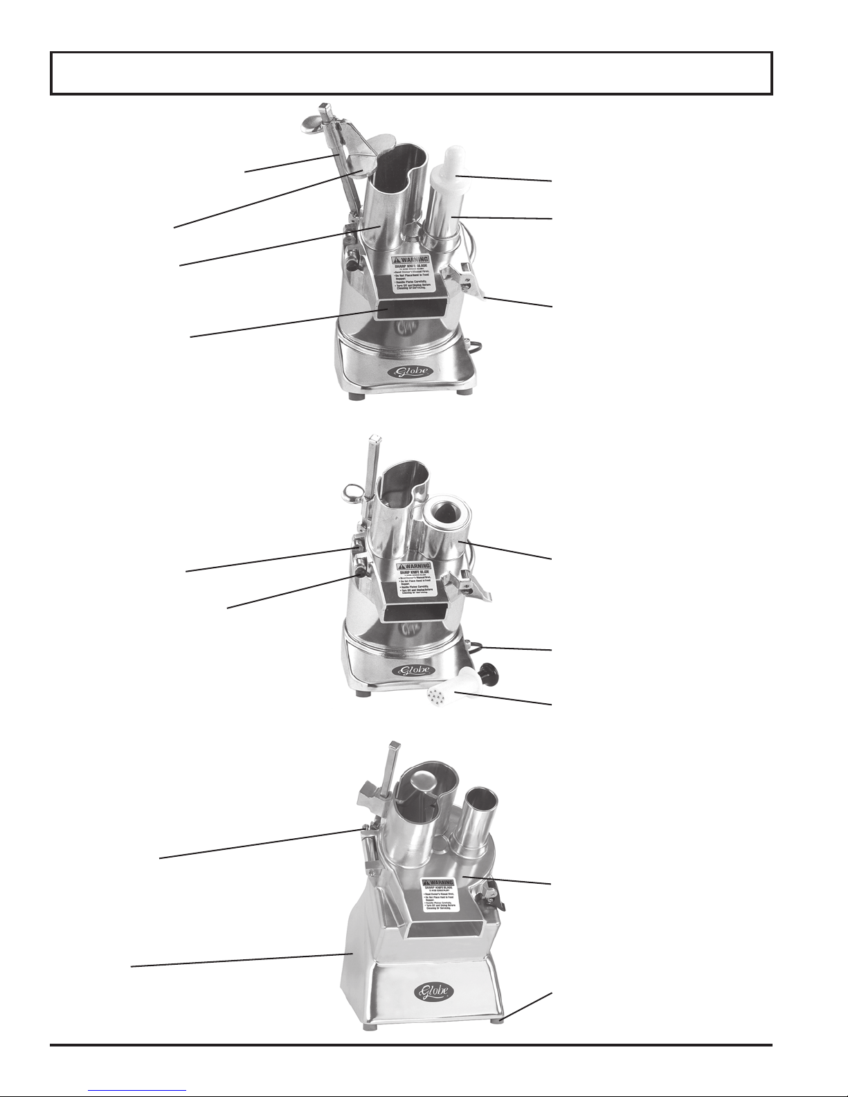
Key Components of the Vegetable Cutter
Foodpusher Guide Rod
Foodpusher
Food Hopper
Ejection Chute
Hopper Hinge
Plastic Food Pusher
Continuous Feed Food Hopper
On/Off Latch
GFP500
Continuous Feed Food Hopper
Hopper Hinge Screw
Hinge Pin
Base
Power Cord
Plastic Food Pusher
GFP550
Hopper Head
Rubber Feet
Page 4
GFP700
Page 5

Installation and Proper Grounding
UNPACKING:
1. Unpack the vegetable cutter immediately after receipt. If the machine is found to be damaged, save the
packaging material and contact the carrier within fifteen (15) days of delivery. Immediately contact your
source of the equipment. You have no recourse to damage after fifteen (15) days.
2. An ejector plate, foodpusher , and instruction manual are packed with the vegetable cutter. If you did not
receive all of these materials, contact Globe or your local supplier.
TO AVOID SERIOUS PERSONAL INJURY PROPERLY
INSTALL VEGETABLE CUTTER IN ADEQUATE WORK AREA
• ALWAYS install equipment in a work area with adequate light and space.
• ONLY operate the vegetable cutter on a solid, level, nonskid surface.
• NEVER bypass, alter, or modify this equipment in any way from its original condition. Doing so may create
hazards and will void warranty.
• ALWAYS carry the unit with both hands underneath the unit.
• NEVER attempt to carry the unit by holding the ejection chute or foodpusher handle.
• NEVER operate without the warning label attached.
INSTALLATION:
1. Read this manual thoroughly before installation and operation. DO NOT proceed with installation and
operation if you have any questions or do not understand anything in the manual. Contact your local
representative or Globe first.
2. Remove the vegetable cutter from the corrugated box.
3. Make sure the rubber feet are firmly tightened.
NEVER use the vegetable cutter without the rubber feet inst alled.
4. Select a location for the vegetable cutter that has a level, solid, nonskid surface and a well-lighted work area
away from children and visitors.
ALWAYS carry the unit with both hands underneath the unit.
Page 5
Page 6

Installation and Proper Grounding
THIS MACHINE IS PROVIDED WITH A THREE-PRONG GROUNDING PLUG. THE OUTLET TO WHICH
THIS PLUG IS CONNECTED MUST BE PROPERLY GROUNDED. IF THE RECEPTACLE IS NOT THE
PROPER GROUNDING TYPE, CONTACT AN ELECTRICIAN. DO NOT UNDER ANY CIRCUMSTANCES
CUT OR REMOVE THE THIRD GROUND PRONG FROM THE POWER CORD OR USE ANY ADAPTER
PLUG (FIG. 6-1 AND FIG. 6-2).
5. Inspect the vegetable cutter to ensure all parts have been provided.
6. Make sure the hopper head of the vegetable cutter is in place.
7. Make sure the warning label is properly positioned and legible and the instruction manual is available near the
vegetable cutter .
8. Complete the warranty card and mail to the Globe factory or register online at www.globeslicers.com.
9. Clean the vegetable cutter using the procedures outlined in the cleaning section (pages 12 and 13) prior to
using the vegetable cutter.
10. Contact your local representative or Globe directly if you have any questions or problems with the installation
or operation of this vegetable cutter .
Fig. 6-1 Correct
Page 6
Fig. 6-2 Incorrect
Page 7

Operating Instructions
SHARP KNIFE BLADE
TO AVOID SERIOUS PERSONAL INJURY:
• NEVER put your hand in the food hopper with the on/off latch in the ON position.
•ALWAYS turn the vegetable cutter off and unplug the unit before cleaning or servicing.
• DO NOT immerse the unit in water.
•ALWAYS keep fingers away from sharp knife edges and handle discs with extreme care. Cutting edges of
the discs are extremely sharp.
• DO NOT leave discs in soapy water. Always clean the cutting discs immediately after each use. Handle the
cubing/dicing knife with extreme care!
• DO NOT carry the unit by holding the ejection chute or food pusher handle.
•ALWAYS carry the unit with both hands underneath the unit.
•ALWAYS use the foodpusher or plastic pusher to feed product.
OPERATING THE VEGET ABLE CUTTER
1. Unplug the vegetable cutter .
2. Lift the on/off latch upward to the OFF position and raise the hopper head to the left
so it rests in the open position (Fig. 7-1).
3. Place the ejector plate onto the drive shaft. Turn the plate until the pin is properly
aligned with the alignment pin on the drive shaft (Fig. 7-2). The plate should be flat
against the housing.
4. Select appropriate cutting disc and install it onto the drive shaft (see disc installation
and removal section pages 9 through 11 for instructions).
Fig. 7-1
5. Lower the hopper head to its closed position. Do not push down on the on/off latch
at this time.
NOTE: The hopper head will not close if the disc is not installed correctly. DO NOT
use force. If the hopper head does not close properly , make sure the vegetable cutter
is unplugged and reinstall the disc.
Fig. 7-2
Page 7
Page 8

Operating Instructions
6. Lift the foodpusher up to its highest position and tilt it to the left (Fig. 8-1).
7. Plug in the vegetable cutter .
8. Place a food container under the ejection chute.
9. Trim the food product to fit into the food hopper. Food must not extend above the top
of the hopper.
10. Place the product in the food hopper. Long products can be continuously fed into
the continuous feed food hopper using the plastic foodpusher to feed the product.
NOTE: When using the continuous feed food hopper the foodpusher for the kidney
shaped hopper must be in the lowered position (Fig. 8-2). The vegetable cutter will not
operate if the kidney shaped hopper is open.
11. Lift the foodpusher up and tilt it to the right until the foodpusher covers the hopper
opening.
12. Press the foodpusher according to the resistance of the material being processed in
order to hold the product and keep it from rotating.
Fig. 8-1
NOTE: Do not apply heavy pressure with the foodpusher while processing or food
will not maintain a uniform cut.
13. Push the on/off latch downward to the ON position. The vegetable cutter will be
activated at this point. The foodpusher is interlocked and activates the unit as long
as the latch is down in the ON position (Fig. 8-2).
NOTE: The foodpusher must fully cover hopper opening or the vegetable cutter
will not start.
DO NOT put hand in hopper with the on/off latch in the ON position.
ALWAYS use the foodpusher or plastic pusher to feed product.
14. Lift the on/off latch upward to the OFF position to stop the vegetable cutter.
15. Pull the foodpusher up to its highest position and tilt it to the left.
16. Repeat steps 10 through 15 until all product is cut.
17. Unplug the vegetable cutter.
18. Raise the hopper head to the left so it rests in the open position.
Fig. 8-2
19. Remove cutting disc for cleaning before slicing a different product (see disc installation/removal section pages
9 through 11 and cleaning section pages 12 and 13 for instructions).
Page 8
Page 9

Disc Installation and Removal
DISC INST ALLATION
NOTE: For ease of installation and removal of discs, the center of the disc (mounting hole) and the disc drive shaft
must be clean and dry.
NOTE: Make sure the ejector plate is securely on the drive shaft before installing the cutting disc.
DO NOT use force or tools to install and remove discs.
Cutting edges of discs are extremely sharp. Always keep fingers away from sharp knife edges and
handle discs with extreme care. A cut resistant glove can be used if desired.
SINGLE DISCS
1. Carefully hold the disc (palm up) with the disc hub down and place the disc onto the
drive shaft (Fig. 9-1).
2. Turn the disc until the drive pins line up with the slots on the disc hub and the disc is
securely on the drive shaft (Fig. 9-2 and Fig. 9-3).
Fig. 9-1
FRENCH FRY DISCS
NOTE: When using the french fry discs always be sure to use the top slicing disc with the
matching sized lower disc. Check the disc number imprinted on the back of each disc for a
proper match.
1. Carefully hold the lower disc (palm up) with the cutting grids up.
2. Place the lower disc onto the drive shaft.
3. Turn the lower disc until it locks into position and the cutting grids line up with the
ejection chute (Fig. 9-4).
4. Carefully hold the upper disc (palm up) with the disc hub down and place it on the drive
shaft (Fig. 9-5).
5. Turn the upper disc until the drive pins line up with the slots on the disc hub and the disc
is securely on the drive shaft (Fig. 9-6).
Disc Hub
Drive Shaft
Fig. 9-2
Fig. 9-3
Fig. 9-4 Fig. 9-5 Fig. 9-6
Page 9
Page 10

Disc Installation and Removal
CUBING/DICING DISCS
NOTE: When using the cubing/dicing discs always be sure to use the knife
with the matching sized grid or disc. Check the number imprinted on the
knife and back of the grid or disc for proper match.
NOTE: GFP700 and GFP750 - Make sure the cubing/dicing frame is in the
disc body correctly. The tab on the frame should lie against the rim of the
disc (Fig. 10-1).
1. Carefully hold the grid or disc (palm up) with sharp blades up.
2. Place the grid or disc on the drive shaft.
3. GFP700 and GFP750 only - Turn the disc until it falls into a locked position and the grid portion lines up with
the opening in the hopper head (Fig. 10-2).
4. Handle the knife by the thick side only and keep fingers away from cutting edge. Carefully place the
cubing/dicing knife with hub down onto the drive shaft (Fig. 10-3).
5. Carefully turn the knife until the drive pins line up with the slots on the knife hub and the knife is securely on the
drive shaft (Fig. 10-4).
Fig. 10-1
GFP500 and GFP550
GFP700 and GFP750
Fig. 10-2
Fig. 10-3
Fig. 10-4
Page 10
Page 11

Disc Installation and Removal
DO NOT use force or tools to install and remove discs.
Cutting edges of discs are extremely sharp. Always keep fingers away from sharp knife edges and
handle discs with extreme care. A cut resistant glove can be used if desired.
DISC REMOVAL
SINGLE DISCS
1. Carefully place hand under disc (palm up) rotate disc slightly back and forth and lift up at the disc hub.
CUBING/DICING DISCS
When removing and handling the cubing/dicing disc hold the knife
and cutting grid together with both hands.
The cubing/dicing knife is extremely sharp. Handle knife with care.
1. Being careful not to touch the cutting edges of the knife or grid, turn the
knife counter clockwise to position shown. Hold the knife in that position with
one hand. At the same time place the other hand (palm up) under the lower disc
and lift up at disc hub removing both knife and disc at the same time (Fig. 11-1).
FRENCH FRY DISCS
When removing and handling the french fry disc hold the upper
and lower discs together with both hands.
1. Being careful not to touch the cutting edge of the knife turn the slicing disc counter
clockwise to position shown. Hold the slicing disc in that position with one hand.
At the same time place the other hand (palm up) under the lower disc and lift up
removing both discs at the same time (Fig. 1 1-2).
GFP500 and GFP550
GFP700 and GFP750
Fig. 11-1
Fig. 11-2
Page 11
Page 12

Cleaning
NOTE: Clean and sanitize the vegetable cutter before using the first time, after each use, and before cutting
different types of food products.
Unplug the vegetable cutter before cleaning or handling.
• DO NOT use caustic or abrasive cleaners.
• DO NOT wash the hopper head or discs in the dishwasher.
• DO NOT try to remove food from the discs by banging them on a hard surface. This will damage the
cutting discs.
DISASSEMBLY
1. Unplug the vegetable cutter.
2. Lift the on/off latch upward to the OFF position. DO NOT raise the hopper head at this time.
3. Remove the hopper head from the base.
a. GFP500 and GFP550 - Loosen and remove the screw from the bottom of hinge. Lift the hopper head up
and away from the base.
b. GFP700 and GFP750 - Pull the hinge pin out from the top. Remove hopper head from base.
4. Wash the hopper head with warm, soapy water, and a wash cloth. Remove all food particles and juices from
the food hopper and foodpusher guide rod.
When handling discs keep fingers and hands away from the cutting edge.
DO NOT leave the discs in soapy water. Always clean the cutting discs immediately after each use.
NEVER leave the knife in soapy water. Handle the cubing/dicing knife with extreme care.
5. Remove the cutting disc (see disc installation/removal section page 9 through 11 for instructions) and wash
the disc in warm soapy water. When cleaning the cubing/dicing knife carefully wipe from the thick side out.
NOTE: A cleaning brush can be used for cleaning the cutting discs if desired.
6. Remove the ejector plate by lifting it off the disc drive shaft. Wash the food ejector in warm soapy water. Also
wash the disc housing with a cloth and warm soapy water.
7. Clean the base of the vegetable cutter and cutting area with warm soapy water and a cloth.
8. Make sure that all surfaces are dry before reassembling the unit.
Page 12
Page 13

Cleaning
REASSEMBLY
1. Reinstall the hopper head by aligning the hinge with the base.
2. Secure the hopper head to the base.
a. GFP500 and GFP550 - Insert the hopper hinge pins into the hinge slots located on the base. Secure the
head by tightening the bottom hinge screw.
b. GFP700 and GFP750 - Line up the hopper head with the base and insert the hinge pin.
3. Place the ejector plate on the drive shaft. T urn plate until pin is properly aligned with the alignment pin on the
drive shaft.
4. Return the hopper head to its closed position.
Page 13
Page 14

Discs and Accessories Available
500 SERIES
DISC3PK-5
F1-5
F2-5
G3-5
G4-5
G6-5
G8-5
G10-5
G12-5
not available
SU5-5
SU8-5
TO-5
S1.5-5
S2-5
not available
S3-5
PA4-5
PA5-5
BT7-5
not applicable
14-5
not available
11-5
9-5
7-5
4-5
3-5
1-5
R-5
00-5
W8-5
not available
W10-5
not available
W14–5
not available
W6-5
P8-5
W20-5
W28-5
BT6-5
BT8-5
BT10-5
HS-5
K2.5-5
not available
not available
BR3-5
BR4-5
PG4-5
PG6-5
not available
700 SERIES
DISC3PK-7
F1-7
F2-7
G3-7
G4-7
G6-7
G8-7
G10-7
G12-7
G16-7
SU5-7
SU8-7
TO-7
S1.5-7
S2-7
PA3-7
not available
PA4-7
not available
BT7-7
PH-9
14-7**
K4-7**
11-7**
9-7**
7-7**
4-7**
3-7**
1-7**
R-7**
00-7**
W8-7
W8F-7
W10-7
W10F-7
W14-7
W14F-7
W6-7
not available
not available
W28-7
not available
BT8-7
BT10-7
not available
K2.5-7
14FD-7
KP14-7
BR-7
BR4-7
PG4-7
not available
PG8-7
SPECIFICATIONS
Slicing Disc 5/64”, Slicing Disc 5/32”, Shredding Disc 3/16”, WR3
Slicing Disc, 1/32” (1mm) cut size
Slicing Disc, 5/64” (2mm) cut size
Slicing Disc, 1/8” (3mm) cut size
Slicing Disc, 5/32” (4mm) cut size
Slicing Disc, 15/64” (6mm) cut size
Slicing Disc, 5/16” (8mm) cut size
Slicing Disc, 3/8” (10mm) cut size
Slicing Disc, 15/32” (12mm) cut size
Slicing Disc, 5/8” (16mm) cut size
Slicing Disc, 3/16” (5mm) wavy cut size
Slicing Disc, 5/16” (8mm) wavy cut size
Tomato Slicing Disc, 3/16” (5mm) cut size
Julienne Disc, 1/16” (1.5mm) square cut size
Julienne Disc, 5/64” (2mm) square cut size
Julienne Disc, 1/8” (3mm) square cut size
Julienne Disc, 1/8” x 5/64” (3mm x 2mm)) square cut size
Julienne Disc, 5/32 (4mm) square cut size
Julienne Disc, 3/16" x 5/32" (5mm x 4mm) square cut size
Julienne Disc, 9/32” (7mm) square cut size
Plate Holder - Only 1 required.
Grating Disc, fine cut (parmesan and romano cheese powder)
Coarse Grating Plate
Shredding Disc, 5/64” (2mm) cut size
Shredding Disc, 3/32” (2.5mm) cut size
Shredding Disc, 1/8” (3mm) cut size
Shredding Disc, 5/32” (4mm) cut size
Shredding Disc, 3/16” (5mm) cut size
Shredding Disc, 9/32” (7mm) cut size
Shredding Disc, 23/64” (9mm) cut size
Shredding Disc, 7/16” (1 1mm) cut size
Cubing Disc, 5/16” (8mm) cube cut size
Full Cubing Grid Disc, 5/16” (8mm) cube cut size
Cubing Disc, 3/8” (10mm) cube cut size
Full Cubing Grid Disc, 3/8” (10mm) cube cut size
Cubing Disc, 9/16” (14mm) cube cut size
Full Cubing Grid Disc, 9/16” (14mm) cube cut size
Dicing Disc, 1/4" x 1/4" x 5/16" (6mm x 6mm x 8mm) cut size
Dicing Disc, 5/16" x 5/16" x 1/8" (8mm x 8mm x 3mm) cut size
Dicing Disc, (23mm x 23mm x 14mm) cube size
Dicing Disc, (28mm x 28mm x 14mm) cube size
French Fry Disc, 15/64” (6mm) square cut size
French Fry Disc, 5/16” (8mm) square cut size
French Fry Disc, 3/8” (10mm) square cut size
Shaving Disc, 1/64” (.5mm) cut size
Specialty Shredding Disc, 3/32” (2.5mm) cut size
Grating Disc, fine cut (parmesan and romano cheese powder)
Potato Grating Disc
* Brunoise Disc, 1/8” (3mm) small diamond shape cut size
* Brunoise Disc, 5/32” (4mm) small diamond shape cut size
* Gaufrette Disc, 5/32” (4mm) waffle design cut size
* Gaufrette Disc, 15/64” (6mm) waffle design cut size
* Gaufrette Disc, 5/16” (8mm) waffle design cut size
*Discs For GFP550 and GFP750 Only
PH-9 Plate Holder.
the shredding and
grating plates are
**NOTE: These
plates require a
Only 1 PH-9 is
needed because
interchangeable.
Page 14
Page 15

Discs and Accessories Available
ITEM
DESCRIPTION
GFP500/GFP550 Models
W8G-5
W8GW-5
W10G-5
W14G-5
W6G-5
W20G-5
W20B-5
W8K-5
W10K-5
W14K-5
P8K-5
EP-5
P500
P550L
Cubing Grid Only (for W8-5 disc)
Welded Cubing Grid Only (for W8-5 disc)
Cubing Grid Only (for W10-5 disc)
Cubing Grid Only (for W14-5 disc)
Dicing Grid Only (for W6-5 disc)
Dicing Grid Only (for W20-5 disc)
Dicing Grid Body Only (for W20-5 disc)
Cubing Knife Only (for W6-5 and W8-5 disc)
Cubing Knife Only (for W10-5 disc)
Cubing Knife Only (for W14-5 and W20-5 disc)
Dicing Knife Only (for P8-5 disc) (Can be used with W8-5 grid)
Ejector Plate
Food Pusher for Continuous Feed Hopper (plastic) (GFP500 only)
Food Pusher for Continuous Feed Hopper (plastic) (GFP550 only)
GFP700/GFP750 Models
W8B-7
W10B-7
W14B-7
W8G-7
W10G-7
W14G-7
W6G-7
W28G-7
W8K-7
W10K-7
W14K-7
EP-7
P500
P750
Cubing Body Only (for W6-7 and W8-7 disc)
Cubing Body Only (for W10-7 disc)
Cubing Body Only (for W14-7 and W28-7 disc)
Cubing Grid Insert Only (for W8-7 disc)
Cubing Grid Insert Only (for W10-7 disc)
Cubing Grid Insert Only (for W14-7 disc)
Dicing Grid Insert Only (for W6-7 disc)
Dicing Grid Insert Only (for W28-7 disc)
Cubing Knife Only (for W6-7 and W8-7 disc)
Cubing Knife Only (for W10-7 disc)
Cubing Knife Only (for W14-7 and W28-7 disc)
Ejector Plate
Food Pusher for Continuous Feed Hopper (plastic) (GFP700 only)
Food Pusher for Continuous Feed Hopper (plastic) (GFP750 only)
All Vegetable Cutter Models
CB
FKIT
Cleaning Brush
File Kit
DISC STORAGE CASES
MODEL
GFP500/GFP550 Models
SCV-1
SCH-3
SCH-4
GFP700/GFP750 Models
SCH-7
All Vegetable Cutter Models
WR3
Vertical Case (High Impact Molded Plastic) (Not for french fry, cubing, or dicing discs)
Horizontal Case (High Impact Molded Plastic)
Horizontal Case (High Impact Molded Plastic)
Horizontal Case (Welded Stainless Steel)
3 Peg Wall Rack
SPECIFICATIONS
Page 15
Page 16

Limited Warranty
Globe Food Equipment Company (“GFE”) warrants to the original purchaser of new equipment that said
equipment, when installed in accordance with our instructions within the United States and subjected to normal
use, is free from defects in material or workmanship for a period of 2 years on parts (excludes wear/expendable
parts and all cutting discs and parts thereof). The labor warranty is 2 years on labor from original installation, or
30 months from actual shipment date, whichever date occurs first.
THIS WARRANTY IS IN LIEU OF ALL OTHER WARRANTIES, WHETHER EXPRESS OR IMPLIED. GFE
EXPRESSLY DISCLAIMS ANY IMPLIED WARRANTY OF MERCHANTABILITY OR EXPRESS OR IMPLIED
WARRANTY OF FITNESS FOR A PARTICULAR PURPOSE.
GFE’S OBLIGATION AND LIABILITY UNDER THIS WARRANTY IS EXPRESSLY LIMITED TO
REPAIRING AND REPLACING EQUIPMENT WHICH PROVES TO BE DEFECTIVE IN MATERIAL OR WORKMANSHIP WITHIN THE APPLICABLE WARRANTY PERIOD. All repairs pursuant to this
Warranty will be performed by an Authorized Designated GFE Service Location during normal working hours. IN
NO EVENT SHALL GFE BE LIABLE FOR INCIDENTAL OR CONSEQUENTIAL DAMAGES TO BUYER OR ANY
THIRD PARTY, INCLUDING, WITHOUT LIMITATION, LOSS OF PROPERTY, PERSONAL INJURY, LOSS OF
BUSINESS OR PROFITS OR OTHER ECONOMIC LOSSES, OR STATUTORY OR EXEMPLARY DAMAGES,
WHETHER IN NEGLIGENCE, WARRANTY, STRICT LIABILITY, OR OTHERWISE.
This Warranty is given only to the first purchaser from a retail dealer. No warranty is given to
subsequent transferees.
Periodic maintenance of equipment and other adjustments required due to installation set up or normal wear are
not covered under this warranty.
This Warranty is not in force until such time as a properly completed and signed Installation/Warranty Registration
has been received by GFE within 30 days from the date of installation.
THE FOREGOING WARRANTY PROVISIONS ARE A COMPLETE AND EXCLUSIVE STATEMENT BETWEEN
THE BUYER AND SELLER. GFE NEITHER ASSUMES NOR AUTHORIZES ANY
PERSONS TO ASSUME FOR IT ANY OTHER OBLIGATION OR LIABILITY IN CONNECTION WITH SAID
EQUIPMENT.
Example of items not covered under warranty, but not limited to just these items:
1. Acts of God, fire, water damage, burglary, accident, theft.
2. Freight damage.
3. Improper installation or alteration of equipment.
4. Use of generic or after market parts.
5. Repairs made by anyone other than a GFE designated servicer.
6. Lubrication.
7. Expendable wear parts including all cutting discs and parts thereof.
8. Cleaning of equipment.
9. Misuse or abuse.
Page 16
 Loading...